O'Reilly Media -- Template for Microsoft Word H… · Web viewUSB A-to-B cables for each Arduino...
16
Rob Faludi, http://faludi.com 3/6/2022 Horsie Race This project can serve as a model for almost any many-to-one network you’d like to build. You will create a carnival midway-style horse race using a wireless audio input that transmits each player’s yells and cheers to a base station radio. This base station will be connected to a computer where the noise will advance their horse on the screen. Figure 1. Horse race network The example project in Figure 1 shows two sensor nodes and a base station. That’s three radios in total. If you have only two radios, you can build it with a single sensor node and the base station. Parts 2 solderless breadboards (AF 64, DK 438-1045-ND, SFE PRT- 09567) 1
Transcript of O'Reilly Media -- Template for Microsoft Word H… · Web viewUSB A-to-B cables for each Arduino...

Rob Faludi, http://faludi.com 5/8/2023
Horsie RaceThis project can serve as a model for almost any many-to-one network you’d like to build. You will create a carnival midway-style horse race using a wireless audio input that transmits each player’s yells and cheers to a base station radio. This base station will be connected to a computer where the noise will advance their horse on the screen.
Figure 1. Horse race network
The example project in Figure 1 shows two sensor nodes and a base station. That’s three radios in total. If you have only two radios, you can build it with a single sensor node and the base station.
Parts 2 solderless breadboards (AF 64, DK 438-1045-ND, SFE PRT-09567) Hook-up wire or jumper wire kit (AF 153, DK 923351-ND, SFE PRT-00124) 2 9-volt or 5-volt power supplies (9 volt batteries also work well for short-term use)
(AF 63, or 80 with 9V battery, RS 273-355, SFE TOL-08269 or TOL-00298) 2 Arduino Unos (SFE DEV- 09950, AF 50) USB A-to-B cables for each Arduino (AF 62, DK 88732-9002, SFE CAB-00512) 2 breakout boards with electret microphone (SFE BOB-09964)
1

Rob Faludi, http://faludi.com 5/8/2023
3 XBee Series 1 radios, configured with version 10E8 or later (Digi: XB24-AWI-001, DK XB24-AWI-001-ND).
2 XBee breakout boards with male headers and 2mm female headers installed (AF 126 (add SFE PRT-00116), SFE BOB-08276 & PRT-08272 & PRT-00116)
XBee USB Serial adapter (XBee Explorer, Digi Evaluation board or similar) (AF 247, SFE WRL-08687)
USB cable for XBee adapter (AF 260 , SFE CAB-00598) Wire strippers (AF 147, DK PAL70057-ND, SFE TOL-08696)
Mark one of the radios with a B for base station and give the other numbers like 1 and 2 so you can tell the difference between them once they’re configured.
Prepare Your Base Station RadioStart with the first radio, the one you’ve selected to be the base station. Use your serial terminal program and AT commands (or X-CTU if you have access) to configure this radio with the settings in Table 1.
Table 1. Base station radio setup for horsie race
Function Command Parameter
PAN ID ATID 3001 (any address from 0 to FFFE will do)
MY Address ATMY 0
The Destination addressing doesn’t matter here because the base station will only be receiving data, never sending it. When you’re finished, check your work by reissuing each AT command without any parameter so the radio can show you the addresses it’s using. As a final step, use the ATWR command to write the new configuration to your radio’s firmware so it’s saved for the next power-up.
You should get an OK response after issuing each command to set parameters, and another OK response when you write the changes to firmware. If you don’t get an OK response, most likely you took more than ten seconds to issue the command and you’ve dropped out of command mode. This can happen quite frequently when you’re starting out, but you’ll get better at it as you go along. The other common mistake is not issuing the ATWR command to save your changes, then losing your configuration when the radio is powered down.
Prepare Your Sensor RadiosReplace the base station radio with one other other radios radio you marked with numbers to use as sensor radios. Use your serial terminal program and AT commands (or X-CTU if you have access) to configure each sensor radio with the settings in Table 2.
Table 2. Sensor radio setup for horsie race
2

Rob Faludi, http://faludi.com 5/8/2023
Function Command Parameter
PAN ID ATID 3001 (must be the same for all radios on your network)
MY address ATMY 1 (*each sensor radio must have a UNIQUE address from 1 to FFFE)
Destination address high ATDH 0
Destination address low ATDL 0
When you’ve finished configuring each radio, check your work by reissuing each AT command without any parameter so the radio can show you the addresses it’s using.
As a final step, use the ATWR command to write the new configuration to your radio’s firmware so it’s saved for the next power-up.
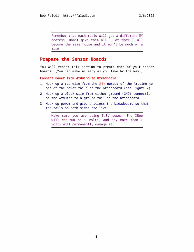
Remember that each radio will get a different MY address. Don’t give them all 1, or they’ll all become the same horse and it won’t be much of a race!
Prepare the Sensor BoardsYou will repeat this section to create each of your sensor boards. (You can make as many as you like by the way.)
Connect Power from Arduino to Breadboard1. Hook up a red wire from the 3.3V output of the Arduino to one of the power rails on
the breadboard (see Figure 2)2. Hook up a black wire from either ground (GND) connection on the Arduino to a
ground rail on the breadboard3. Hook up power and ground across the breadboard so that the rails on both sides are
live.
Make sure you are using 3.3V power. The XBee will not run on 5 volts, and any more than 7 volts will permanently damage it.
3
Rob Faludi, http://faludi.com 5/8/2023
Figure 2. Power connections on Arduino
XBee Breakout Board
Your XBee radio has pins spaced 2 mm apart. This helps keep the component small, but it means you can’t use it directly on a standard 0.1″ spaced solderless breadboard. To mate it with the breadboard, you need to use a breakout board. Basic breakout boards have no other electrical components. Another option is to use certain XBee USB-serial adaptors, such as the XBee Explorer, Adafruit XBee Adaptor, or MCPros XBee Simple Board, all of which come with standard-spaced holes where you can solder on male headers. In this example, we’ll just work with a basic breakout board.
1. Solder regular 0.1″ spaced male headers onto the two center rows of holes on your basic XBee breakout board. The male headers come in long strips, and must be cut down to fit the breakout board before soldering. It’s a good idea to place the male headers into the breakout board and insert them into the breadboard, as this helps with stability while soldering.
2. Next, flip the board over and solder two strips of female 2 mm-spaced sockets onto the opposite side of the breakout board.
3. Test-fit the XBee into the female sockets, being careful not to bend its pins (see Figure 3).
4

Rob Faludi, http://faludi.com 5/8/2023
Figure 3. Finished breakout board with XBee mounted
XBee Connections1. With the XBee mounted on its breakout board, position the breakout board in the
center of your breadboard so that the two rows of male header pins are inserted on opposite sides of the center trough.
2. Use red hookup wire to connect pin 1 (VCC) of the XBee to 3.3 volt power. See Figure 5.
3. Use black hookup wire to connect pin 10 (GND) of the XBee to ground.4. Use yellow (or another color) hookup wire to connect pin 2 (TX / DOUT) of the
XBee to digital pin 0 (RX) on your Arduino (see Figure 6).5. Finally, use blue (or another color) hookup wire to connect pin 3 (RX / DIN) of your
XBee to digital pin 1 (TX) on your Arduino. Figure 5 shows the connections to the XBee.
Repeat these steps again with the other Arduino and XBee. Figure 6 shows the circuit diagram, and 7 shows the schematic.
Sometimes it’s a good idea to use a 1µF capacitor to decouple the power supply and filter out high-frequency noise that might interfere with your radio’s ability to transmit or receive a clean signal. The Arduino typically provides clean enough power on its own. Decoupling is essential if you use a separate 3.3 V voltage regulator. In that case place the negative leg of the capacitor into ground and the positive leg into power, as near as you can to where your XBee is in the circuit.
5

Rob Faludi, http://faludi.com 5/8/2023
Figure 4. Transmit and Receive connections on Arduino
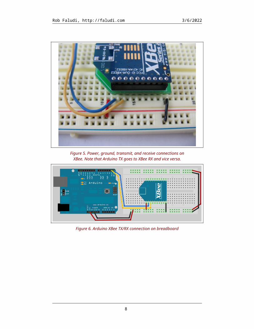
Figure 5. Power, ground, transmit, and receive connections on XBee. Note that Arduino TX goes to XBee RX and vice versa.
6

Rob Faludi, http://faludi.com 5/8/2023
Figure 6. Arduino XBee TX/RX connection on breadboard
Figure 7. XBee Arduino TX/RX connections in schematic view
Audio Input
This project uses an electret condenser microphone, mounted on the SparkFun breakout board. This microphone, like all sound sensors, has an alternating current output. You can get the data sheets for the microphone and its breakout board at http://www.sparkfun.com/products/9964
7
Rob Faludi, http://faludi.com 5/8/2023
1. The microphone breakout board has three connections. Trim your male headers down to 3 pins to match the number of connection holes available. Solder the row of male headers into the breakout board as shown in Figure 8.
2. When the board is positioned so that the microphone is at the far side, the leads from left to right are voltage out (that’s the sensor information), negativ, and positive. Insert the microphone board so that each lead is in its own row on the breadboard.
3. Use an orange (or other color) wire to connect the rightmost, voltage out lead to the Arduino’s analog input 0.
4. Use a black wire to connect the center, negative lead to one of the ground rails.5. Use a red wire to connect the leftmost, positive lead to one of the power rails.
Second Sensor Board
Create the second sensor board in the same way as the first. You can make as many sensor boards as you like. The system will work with as few as one or as many as 15 without any adjustment to the software. Figure 9 shows the breadboard layout for our simple sensor network, and Figure 10 shows the schematic.
Figure 8. Male headers soldered to microphone breakout board
8

Rob Faludi, http://faludi.com 5/8/2023
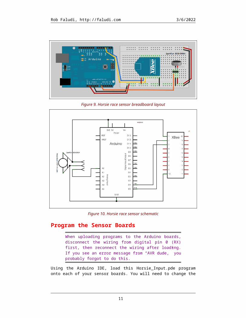
Figure 9. Horsie race sensor breadboard layout
Figure 10. Horsie race sensor schematic
Program the Sensor Boards
When uploading programs to the Arduino boards, disconnect the wiring from digital pin 0 (RX) first, then reconnect the wiring after loading. If you see an error message from “AVR dude,” you probably forgot to do this.
Using the Arduino IDE, load this Horsie_Input.pde program onto each of your sensor boards. You will need to change the horseNumber in line 22 for each different board so that it’s a unique number.
9

Rob Faludi, http://faludi.com 5/8/2023
Be sure to change the horseNumber in line 22 to a unique number for each different board!
/* * *********HORSE RACE SOUND INPUT******** * by Rob Faludi http://faludi.com * with help from Liz Arum http://www.lizarum.com/ */
#define NAME "Horsie Input"#define VERSION "1.00a3"
#define LED_PIN 13#define MIC_PIN 0#define SILENT_VALUE 512 // starting neutral microphone value (self-correcting)
// uses software serial to avoid the Arduino's shared hardware serial pins#include <NewSoftSerial.h>#define RX_PIN 2#define TX_PIN 3NewSoftSerial mySerial=NewSoftSerial(RX_PIN, TX_PIN);
// *******************************************************// SET THIS TO A UNIQUE VALUE that identifies your horseint horseNumber = 1; // *******************************************************
unsigned long interval=1000; // milliseconds between sending values
void setup() { pinMode(LED_PIN,OUTPUT); blinkLED(LED_PIN,2,100); mySerial.begin(9600); Serial.begin(9600);}
void loop() { //read the analog input a number of times int yellValue=getSound(); //send a yell (if it's time) goHorse(yellValue);}
int getSound() { static int average = SILENT_VALUE; // stores the neutral position for the mic static int avgEnvelope = 0; // stores the average sound pressure level int avgSmoothing = 10; // larger values give more smoothing for the average int envSmoothing = 2; // larger values give more smoothing for the envelope int sound=analogRead(MIC_PIN); // look at the voltage coming from the mic int envelope = abs(sound - average); // the distance from this reading to the average avgEnvelope = (envSmoothing * avgEnvelope + envelope) / (envSmoothing + 1); //Serial.println(avgEnvelope); average = (avgSmoothing * average + sound) / (avgSmoothing + 1); //create a new average
10
Rob Faludi, http://faludi.com 5/8/2023
int soundVal =map(envelope,0,1023,0,255); // scale the value to a single byte return soundVal;}
void goHorse(int yell) { static unsigned long lastYell=0; //stores the last time a yell was sent if (millis()-lastYell > interval) { //if it's time to send a yell mySerial.print(255,BYTE); //send the start byte mySerial.print(horseNumber,BYTE); //send the horse number mySerial.print(yell,BYTE); //send the analog loudness value Serial.println(yell); //send the analog loudness value lastYell = millis(); // record the time yell sent }}
////////////////// UTILITIES //////////////////// this function blinks the an LED light as many times as requested, at the requested blinking ratevoid blinkLED(byte targetPin, int numBlinks, int blinkRate) { for (int i=0; i<numBlinks; i++) { digitalWrite(targetPin, HIGH); // sets the LED on delay(blinkRate); // waits for blinkRate milliseconds digitalWrite(targetPin, LOW); // sets the LED off delay(blinkRate); }}
Don’t forget to reconnect the wiring to digital pin 0 (RX) after loading your code!
Prepare the Base StationConnect to Computer
Your base station radio is simply an XBee serial adapter connected to your computer:
4. Select the coordinator XBee you’ve labeled with a “B” and place it into the XBee Explorer.
5. Plug the XBee Explorer into your computer.
Program the Base StationThe Horsie Race base station uses the following Processing program. Download the zip file of all the libraries and resources from the web site (http://faludi.com/downloads/xbee/horsie_race/). Inside the Processing sketch folder for the Horsie Race is subdirectory called data (see Figure 11). The data folder holds all the sound, image and font resources used by the program.
11

Rob Faludi, http://faludi.com 5/8/2023
Figure 1. Directory structure for the Processing sketch program Horsie Race, including sounds, images, fonts, and the Processing “.pde”
sketches themselves.
You MUST replace the port number listed in this code with your actual port number. Look for it in the code around line 12. Port numbers are listed in the console in Processing, as your program starts up.
Once you have loaded the files and directories onto your computer and opened the Horsie_Race.pde in Processing, press the Run button (labeled with a triangle) to launch the display code. It will open in a new window and show a startup screen that lists how many different powered-up sensor nodes are detected, as shown in Figure 12.
Figure 2. Horsie Race startup screen in Processing
12

Rob Faludi, http://faludi.com 5/8/2023
Playing the Game
If one or more of your sensors isn’t being detected, make sure that it is powered on and that all the wiring is correct and secure. Also check to make sure that each sensor was programmed with a unique horseNumber (see above). Once all of your sensors have been detected, press S on the keyboard to start. You’ll hear the “Call to Post” played, after which you will see all the horses, as shown in Figure 13
Figure 13. Horsie Race main screen in Processing, showing 15 horses ready to compete
Yell, cheer, chant or plaintively moan into the microphone on your sensor board to make the horses move. Each board sends one update per second so the exact sound pressure at that moment is what makes it go. Instantaneous sound pressure is somewhat unpredictable, which contributes elements of chance to the race. Your yelling will also be picked up somewhat by your neighbor’s microphone. Since you’ve gone wireless, your physical strategy will be key. The direction you face and whether you hide in the coat closet will influence the speed of your horse.
The first horse across the finish line wins the race! Shower the lucky jockey with champagne, then press S on the keyboard to race again.
13