ORDINANCE NO2 An ordinance amending Chapter 54, “Dallas...
36
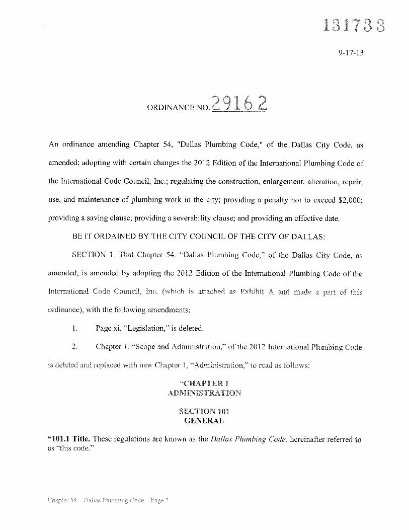
131 3 9-17-13 ORDINANCE NO 2 2 An ordinance amending Chapter 54, “Dallas Plumbing Code,” of the Dallas City Code, as amended; adopting with certain changes the 2012 Edition of the International Plumbing Code of the International Code Council, Inc.; regulating the construction, enlargement. alteration, repair, use, and maintenance of plumbing work in the city; providing a penalty not to exceed $2,000; providing a saving clause; providing a severability clause; and providing an effective date. BE IT ORDAINED BY THE CITY COuNCIL OF THE CITY OF DALLAS: SECTION 1. That Chapter 54. “Dallas Plumbing Code,” of the Dallas City Code, as amended, is amended by adopting the 2012 Edition of the International Plumbing Code of the International Code CounciL Inc (whtch is attached as Exhibit A and made a part of this ordinance), with the following amendments: 1. Page xi, “Legislation,” is deleted. 2 Chapter 1, “Scope and Administration,” of the 2012 International Plumbing Code is deietd and replaced nith ne’a Chapter ‘Administratio to read as folio ‘CHAPTER 1 ADMINIS [RATION SECTION 101 GENERAL “101.1 Title. These regulations are known as the Dallas Plumbing Code, hereinafter referred to as “this codeS’
Transcript of ORDINANCE NO2 An ordinance amending Chapter 54, “Dallas...
131 39-17-13
ORDINANCE NO2 2
An ordinance amending Chapter 54, “Dallas Plumbing Code,” of the Dallas City Code, as
amended; adopting with certain changes the 2012 Edition of the International Plumbing Code of
the International Code Council, Inc.; regulating the construction, enlargement. alteration, repair,
use, and maintenance of plumbing work in the city; providing a penalty not to exceed $2,000;
providing a saving clause; providing a severability clause; and providing an effective date.
BE IT ORDAINED BY THE CITY COuNCIL OF THE CITY OF DALLAS:
SECTION 1. That Chapter 54. “Dallas Plumbing Code,” of the Dallas City Code, as
amended, is amended by adopting the 2012 Edition of the International Plumbing Code of the
International Code CounciL Inc (whtch is attached as Exhibit A and made a part of this
ordinance), with the following amendments:
1. Page xi, “Legislation,” is deleted.
2 Chapter 1, “Scope and Administration,” of the 2012 International Plumbing Code
is deietd and replaced nith ne’a Chapter ‘Administratio to read as folio
‘CHAPTER 1ADMINIS [RATION
SECTION 101GENERAL
“101.1 Title. These regulations are known as the Dallas Plumbing Code, hereinafter referred toas “this codeS’
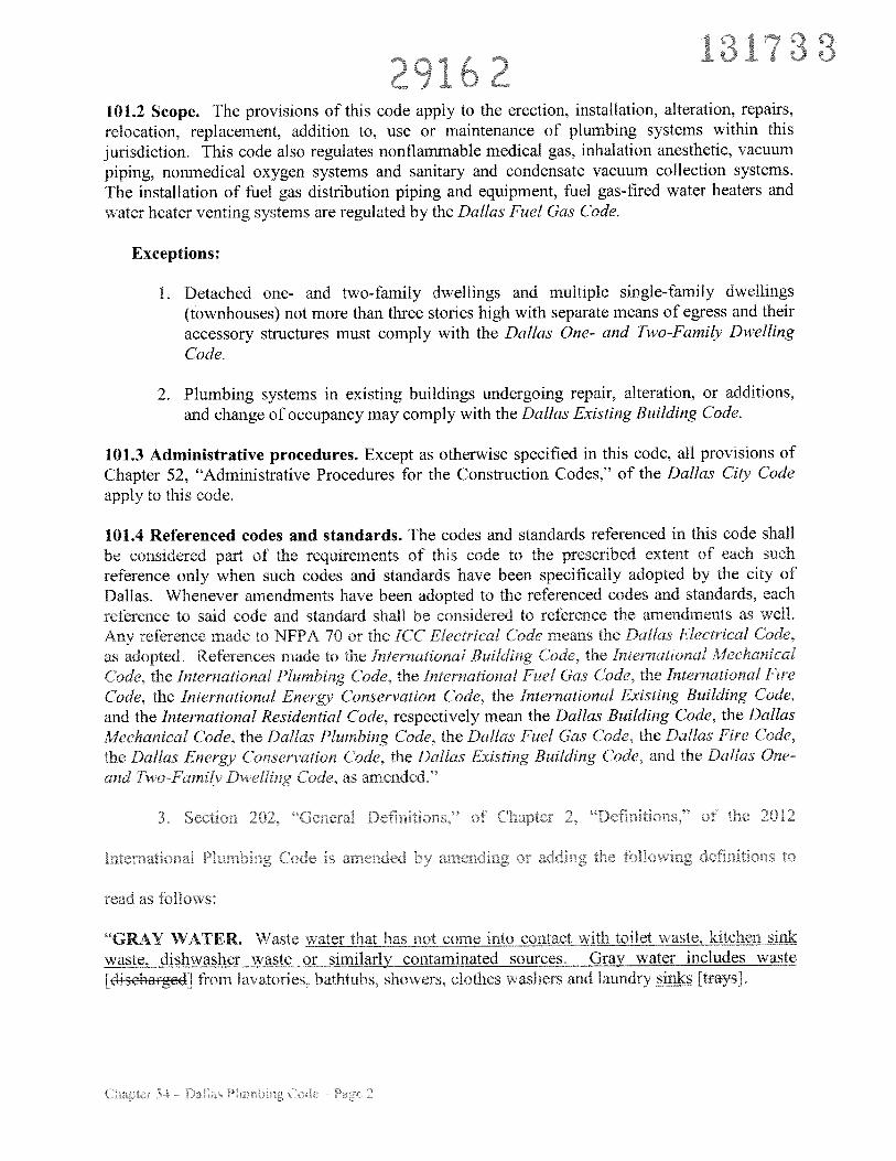
ib101.2 Scope. The provisions of this code apply to the erection, installation, alteration, repairs,relocation, replacement, addition to, use or maintenance of plumbing systems within thisjurisdiction. This code also regulates nonflammable medical gas, inhalation anesthetic, vacuumpiping, nonmedical oxygen systems and sanitary and condensate vacuum collection systems.The installation of fuel gas distribution piping and equipment, fuel gas-fired water heaters andwater heater venting systems are regulated by the Dallas Fuel Gas Code.
Exceptions:
1. Detached one- and two-family dwellings and multiple single-family dwellings(townhouses) not more than three stories high with separate means of egress and theiraccessory structures must comply with the Dallas One- and Two-Family DwellingCode.
2. Plumbing systems in existing buildings undergoing repair, alteration, or additions,and change of occupancy may comply with the Dallas Existing Building Code.
101.3 Administrative procedures. Except as otherwise specified in this code, all provisions ofChapter 52, “Administrative Procedures for the Construction Codes,” of the Dallas City Codeapply to this code.
101.4 Referenced codes and standards. The codes and standards referenced in this code shallbe considered part of the requirements of this code to the prescribed extent of each suchreference only when such codes and standards have been specifically adopted by the city ofDallas. Whenever amendments have been adopted to the referenced codes and standards, eachreference to said code and standard shall be considered to reference the amendments as well.Any reference made to NFPA 70 or the ICC Electrical Code means the Dallas Electrical Code.as adopted. References made to the International Building Code, the International Mechanical(‘ode, the International Plumbing C’ode, the International Fuel Gas C’ode, the International FireC’ode, thc International Energy C’onservation (‘ode, the International Existing Building Code,and the International Residential Code, respectively mean the Dallas Building Code, the DallasMechanical Code, the Dallas Plumbing Code, the Dallas Fuel Gas Code, the Dallas Fire Code,the Dallas Energy C’onsen’ation Code, the Dallas Existing Building (‘ode. and the Dallas One-and Two-Famik Dwelling Code, as amended.”
“I T 4’ ‘ ‘ .. “ 113. J..L_liUIl L’J... “JW1 a ,JcLIj11R,,j’ Li • .. LJ,ISI11LI,J1i,. •.J
“GRAY WATER. Waste water that has not come into contact with_toileyste kitchen sinkwaste, dishwasher waste or similarly contaminated sources. Gray water includes waste[4iseae4] from lavatories, bathtubs, showers, clothes washers and laundry ks [tayJ.
1317332916?
RAINWATER HARVEST. The rainwater collected from roofs and other on-site above groundcatchment systems.
RECLAIMED WATER. Water that, as a result of treatment of domestic wastewater, issuitable for a direct beneficial use or a controlled use when such system has been submitted andapproved by the building official prior to installation.
STORM WATER. A drainage sYstem that carries rainwater, surface water or similar liquidwastes.”
4. Paragraph 305.4.1, “Sewer Depth,” of Subsection 305.4, “Freezing,” of Section 305,
“Protection of Pipes and Plumbing System Components,” of Chapter 3, “General Regulations,”
of the 2012 International Plumbing Code is amended to read as follows:
“305.4.1 Sewer depth. IBuilding sewers that connect to private sewage disposal systemsshall be installed not less than [NUMBER] inches (mm) below finished grade at the point -ofseptic tank connection.] Building sewers shall be a minimum of 12 [installed not less than[NUMBER]] inches (304 mm) below grade.”
5. Subsection 305.7, “Protection of Components of Plumbing System,” of Section 305,
“Protection of Pipes and Plumbing System Components,” of Chapter 3, “General Regulations,”
of the 2012 International Plumbing Code is amended to read as follows:
“305.7 Protection of components of plumbing system. Components of a plumbing systeminstalled within 3 feet of [along] alleyways, driveways, parking garages or other locations ma
exposed to damage shall be recessed into the wall or otherwiseprotected in an approved manner.”
6. Paragraph [M] 3142 1, “Condensate Disposal,” of Subsection [Mj 314.2,
“Eaporators and Cooling Coiis.’ of Section 314, “Condensate DisposaL” of Chapter 3. “General
Regulations.” of the 2)]? lnternatonai Plumbing Code i’. amended to read a folious
“[MI 314.2.1 Condensate disposal. Condensate from all cooling coils and evaporators shallbe conveyed trom the dratn pan eutlefj to an approi ed place of disposal Such piping shallmaintain a horizontal slope in the direction of discharge of not less than one-eighth unitvertical in 12 units horizontal (1 percent slope). Condensate shall not discharge into a street,alley, sidewalk, rooftop or other areas so as to cause a nuisance.”
) I
7, Paragraph [Mj 3 14.2.2, “Drain Pipe Materials and Sizes,” of Subsection [M] 314.2,
“Evaporators and Cooling Coils.” of Section 314, “Condensate Disposal,” of Chapter 3, “General
Regulations,” of the 2012 International Plumbing Code is amended to read as follows:
“IMI 314.2.2 Drain pipe materials and sizes. Components of the condensate disposal
system shall be cast iron, galvanized steel, copper, cross-linked polyethylene, [polybutylene,]
polyethylene, ABS, CPVC or PVC pipe or tubing. When exposed to ultraviolet light,
schedule 80 PVC pipjng injieuired. All components shall be selected for the
pressure and temperature rating of the installation. Joints and connections shall be made in
accordance with the applicable provisions of Chapter 7 relative to the material type.
Condensate waste and drain line size shall be not less than %-inch (19 mm) internal diameter
and shall not decrease in size from the drain pan connection to the place of condensate
disposal. Where the drain pipes from more than one unit are manifolded together for
condensate drainage, the pipe or tubing shall be sized in accordance with Table 314.2.2. jihorizontal sections of drain piping must be installed in uniform alignment at a uniformslope.”
8. Chapter 3, “General Regulations.” of the 2012 International Plumbing Code is
amended by adding a new Section 317, “Irrigation Systems,” to read as follows:
“SECTION 317IRRIGATION SYSTEMS
317.1 Irrigation systems. All irrigation cvsterns must comply with the provisions of Appendix
J, Standards for Designing. Installing and Maintaining I andscape Irrigation Systems.” of this
code.”
9. Subsection 401.1, “Scope,” of Section 401, “General.” of Chapter 4. “Fixtures,
Faucets and Fixture Fittings,” of the 2012 International Plumbing Code is amended to read as
401.1 Scope. this chanter hal’ O\Cfli the matenals, design nd 1nsta1at1on of plumbing
fixtuies, fduCets and ñxlurL fittings in aordan dh th.. tp of Jcitpan. aad shaI prcidc
the minimum number of fixtures for various types of occupancies.are intended to work in oordination with sions of theyjsBui1jizcudShuu1dany conflicts arise between the two chapters. the bufidjfig fficial shall determine which
provision applies.”
?Q1 (/ * ‘
10. Subsection 403.1, “Minimum Number of Fixtures,” of Section 403. “Minimum
Plumbing Facilities,” of Chapter 4, “Fixtures, Faucets and Fixture Fittings,” of the 2012
International Plumbing Code is amended to read as follows:
“403.1 Minimum number of fixtures. Plumbing fixtures shall be provided for the type ofoccupancy and in the minimum number as follows:
1 cmjy occupancies. At least one drinking fountain must be provided at each floorlevel in an approved location.
Exception: A drinking fountain need not be provided in a drinking or diningestablishment.
2. Group A, B, F, 11, I. M and S occupancies. Buildings, tenant spaces or portions ofbuildings where persons are employed must be provided with at least one water closet foreach sex as provided for in Section 403.2.
3. Group E and R occupancies. Fixtures must be provided as shown in Table 403.1
It is recommended, but not required, that the minimum number of fixtures provided alsocomply with the number shown in Table 403.1. Types of occupancies not shown in Table 403.1shall be considered individually by the building [eede] official. The number of occupants shallbe determined by the Dallas [international] Building Code. Occupancy classification shall bedetermined in accordance with the Dallas [International] Building Code.
403,1.1 Fixture calculations. To determine the occupant load of each sex, the total occupantload shall be divided in half. To determine the required number of fixtures, the fixtures ratioor ratios for each fixture type shall be applied to the occupant load of each sex in accordancewith Table 403.1. Fractional numbers resulting from applying the fixture ratios of Table403 1 shall be rounded up to the next whole number. For calculations involving multipleoccupancies, such fractional numbers for each occupancy shall first be summed and thenrounded tc the next whole numbcr.
xception: Ihe total occ rant load shall not cq ii cd to he dividcd i al wherejr,roie1/ aatjstjca1 data diates ulNtrihutlnn o+ W sexes of other tyn oercent of
eacH sex.
403.1.2 Family or assisfedue toiled and bath fitures. Fixtures located within family orassisteduse toilet and bathing rooms required by Section 1109.2.1 of the Dallas[Jna4ienal] Building Code are permitted to he included in the number of required fixturesfor either male or female occupants in assembly and mercantile occupancies.”
.1 ..
11. Subsection 405.6. “Plumbing in Mental Health Centers,” of Section 405, “Installation
of Fixtures,” of Chapter 4, “Fixtures, Faucets and Fixture Fittings,” of the 2012 International
Plumbing Code is deleted.
12. Subsection 409.2, “Water Connection,” of Section 409, “Dishwashing Machines,” of
Chapter 4, “Fixtures, Faucets and Fixture Fittings,” of the 2012 International Plumbing Code is
amended to read as follows:
“409.2 Water connection. The water supply to a commercial dishwashing machine shall beprotected against a backfiow by an air gap or backflow preventer in accordance with Section608.”
13. Subsection 412.4, “Public Laundries and Central Washing Facilities,” of Section 412,
“Floor and Trench Drains,” of Chapter 4, “Fixtures, Faucets and Fixture Fittings,” of the 2012
International Plumbing Code is amended to read as follows:
‘412.4 Public laundries and central washing facilities, in public coin-operated laundries andin the central washing facilities of multiple-family dwellings, the rooms containing automaticclothes washers shall be provided with floor drains located to readily drain the entire floor area.Such drains shall have a minimum outlet of not less than 3 inches (76 mm) in diameter.”
14. Subsection 417.5, “Shower Floors or Receptors,” of Section 417, “Showers,” of
Chapter 4, “Fixtures, Faucets and Fixture Fittings,” of the 2012 international Plumbing Code is
amended to read as follows:
‘417 5 Shower floors or receptors. floor surfaces shall be constructed of imperviousr or c rrosi c nor absorbent and nate p oof natenal i hreshoids nustbc a nini nun of 2mt. it. f in) anci a rnaxir iun ot ic c j229_rnn .rieasure fr r nejp f the draw Ltop )f i 1- r 1-old or darn. l r’ h d st he of suf 1 IC t vidth t accommodi a n w urn
iiij559 un] door.
Exception: Showers desiitned to lv with ICC A\Si A117.l or other siJisapproved by the building official.
417.5.1 Support. Floors or receptors under shower compartments shall be laid on. andsupported by. a smooth and structuralh sound base.
%— •41
‘ i. ‘
417.5.2 Shower lining. Floors under shower compartments, except where prefabricatedreceptors have been provided, shall be lined and made water tight utilizing materialcomplying with Sections 417.5.2.1 through 4 17.5.2.6. Such liners shall turn up on all sidesnot less than 3 [2-] inches (76 [5-1-] mm) above the finished threshold level and shall extendoutward and over the threshold and be fastened to the outside of the threshold jamb to therequired minimum height of the shower liner. Liners shall be recessed and fastened to anapproved backing so as not to occupy the space required for wall covering, and shall not benailed or perforated at any point less than 1 inch (25 mm) above the finished threshold.Liners shall be pitched one-fourth unit vertical in 12 units horizontal (2-percent slope) andshall be sloped toward the fixture drains and be securely fastened to the waste outlet at theseepage entrance, making a water-tight joint between the liner and the outlet. The completedliner shall be tested in accordance with Section 3 12.9.
Exceptions:
1. Floor surfaces under shower heads provided for rinsing laid directly on the groundare not required to comply with this section.
2. Where a sheet-applied, load-bearing, bonded, waterproof membrane is installed asthe shower lining, the membrane shall not be required to be recessed.
417.5.2.1 PVC sheets. Plasticized polyvinyl chloride (PVC) sheets shall meet therequirements of ASTM D 4551. Sheets shall be joined by solvent welding in accordancewith the manufacturer’s installation instructions.
417.5.2.2 Chlorinated polyethylene (CPE) sheets. Nonpiasticized chlorinatedpolyethylene sheet shall meet the requirements of ASTM D 4068. The liner shall bejointed in accordance with the manufacturer’s installation instructions.
417.5.2.3 Sheet lead. Sheet lead shall weigh not less than 4 pounds per square foot (19.5kg/rn2) and shall be coated with an asphalt paint or other approved coating. The leadsheet shall be insulated from conducting substances other than the connecting drain by15-pound (6.80 kg) asphalt felt or an equivalent. Sheet lead shall be joined by burning.
417,5,2.4 Sheet copper. Sheet copper shall contirir to ASTM B I 5 and shall u eigh otess than I ounces per square toot 3.7 kg m). The copper sheet shall he nsuiated fnm
conducting substances other than the connecting drain by 1 5-pound 6 X0 kul asphalt thieo an equi\alent. Sncet copper shall be blued Dv brazing or solaenng.
417.5.2.5 Sheet-applied, load-bearing, honded waterproof membranes. Sheet-applied, ioad-beanng, bonded, waterproof membranes shall meet requirements of ANSIAl 18.10 and shall be applied in accordance with the manufacturer’s installationinstructions.
29 6417.5.2.6 Liquid-type, trowel-applied, load-bearing, bonded waterproof materials.
Liquid-type, trowel-applied, load-bearing, bonded waterproof materials shall meet the
requirements of ANSI Al 18.10 and shall be applied with the manufacturer’s
instructions.”
15. Section 417, “Showers,” of Chapter 4, “Fixtures. Faucets and Fixture Fittings,” of the
2012 International Plumbing Code is amended by adding a new Subsection 417.7, “Test for
Shower Receptors,” to read as follows:
“417.7 Test for shower receptors. Shower receptors must be tested for water tightness by
filling them with water to the level of the rough threshold. The drain must be plugged in a
manner so that both sides of the pan are subjected to the test at the point where the pan is
clamped to the drain.”
16. Subsection [B] 419,3, “Surrounding Material,” of Section 419, “Urinals,” of Chapter
4, “Fixtures, Faucets and Fixture Fittings,” of the 2012 International Plumbing Code is amended
to read as follows:
“IBI 419.3 Surrounding material. Wall and floor space to a point 2 feet (610 mm) in front of a
urinal lip and 4 feet (1219 mm) above the floor and at least 2 feet (610 mm) to each side of the
urinal shall be waterproofed with a smooth, readily cleanable, hard, nonabsorbent material.”
17. Subsection 502.3, “Water Heaters Installed In Attics,” of Section 502. “Installation,”
of Chapter 5. “Water Heaters,” of the 2012 International Plumbing Code is amended to read as
follows:
“502.3 Water heaters installed in attics. Attics containing a water heater shall be provided
with an opening and unobstructed passageway large enough to allow removal of the water
he tcr. The passageway shall be iot less tfar 30 inches jl6 r ri n height ard 22 inches 554
mm in idth and n t nic e thar 20 cci 0Q6 rrn) ii ieitth en meaiirdd aIoig th.
centerline of the passa2ewav from the opening to the water heater The passageway shall have
continuous solid flooring not less than 24 inches t6U lnn) hi nifitl A eei sr\ee spa flOt
less than 30 inches (762 mm) in length [and] 30 inches (762 mm) in width and 30 inches(7(762
iLce shall be piesent at the front or seice side of ihe water heater. The deai acces
opening dimensions shall be not less than 20 inches by 30 inches (5U8 mm by 762 mm) where
such dimensions are large enough to allow removal of the water heater. ya1kyyjQan
appliance must be rated as a floor as approved by the building official. At a minimum, one of
the followingjist be providçd for access to the atticpçç:
733
2. A pull down stair with a minimum 300 lb. (136 kg) capacity.
3. An access door from an upper floor level.
Due to structural conditions, an access panel may be used in lieu of Items 1, 2 or 3 with theprior approval of the building official.”
18. Section 502, “Installation,” of Chapter 5, “Water Heaters,” of the 2012 International
Plumbing Code is amended by adding a new Subsection 502.6, “Water Heaters Above Ground or
Floor,” to read as follows:
“502.6 Water heaters above ground or floor. When the attic, roof, mezzanine or platform inwhich a water heater is installed is more than 8 feet (2438 mm) above the ground or floor level, itmust be made accessible by a stairway or permanent ladder fastened to the building.
Exception: A water heater may be reached by portable ladder if the water heater has acapacity of no more than 10 gallons (or larger with prior approval), it is capable of beingaccessed through a lay-in ceiling, and it is installed not more than 10 feet (3048 mm) abovethe ground or floor level.
502.6.1. Illumination and convenience outlet. Whenever the attic, roof, mezzanine orplatform is not adequately lighted or access to a receptacle outlet is not obtainable from themain level, lighting and a receptacle outlet must be provided in accordance with the DallasElectrical Code.”
19. Subsection 504.6, “Requirements for Discharge Piping,” of Section 504, “Safety
Devices,” of Chapter 5, “Water Heaters,” of the 2012 International Plumbing Code is amended
to read as follows
5046 Requirements for discharge piping. The di 1a c nining sering r chefvaR c, c perature relief vah e n ination thereot sha
\ot he directly LonneLeeci to the draInage system.
2. Discharue through an air gap [located in the same ronn as the atheatefj
3. Not be smaller than the diameter of the outlet of the valve served and shall discharge fullsize to the air gap.
4 r’ ea single reliedei c and shall not connect to iplng seining any other icfdesicepmcn
291o2Exception: Multiple relief devices may be installed to a single T&P discharge pipingsystem when approved by the building official and permitted by the manufacturer’sinstallation instructions and installed pursuant to those instructions.
5. Discharge by indirect means [to the floor, to the pan serving the water heater or storagetank,] to p ppro’ve4 [a] waste receptor or the outdoors.
6. Discharge in a manner that does not cause personal injury or structural damage.
7. Discharge to a termination point that is readily observable by the building occupants.
8. Not be trapped.
9. Be installed so as to flow by gravity.
10. Not terminate less [more] than 6 inches (152 mm) or more than 24 inches (609 mm)above grade nor more than 6 inches (152 mm) above the [floor or] waste receptor.
11. Not have a threaded connection at the end of such piping.
12. Not have valves or tee fittings.
13. Be constructed of those materials listed in Section 605.4 or materials tested, rated andapproved for such use in accordance with ASME Al 12.4. L”
20. Subsection 6044, “Maximum Flow and Wiiter C onsumption” of Section 604,
“Design of Building Water Distribution System.” of Chapter 6, Water Supply and Distribution,”
of the 2012 International Plumbing Code is amended by adding a new Paragraph 604.4.1, “State
Maximum Flow Rate,” to read as follows:
“604 4 1 State maximum flow ate Whet t ic statcn andated maximuir los ate ioreiestr i than el se ems sc the sta c f s rate t kes orecede cc.
i. Suflsccuufl oO4.. \\at ?ressur duing v d1c. n RLgUa0i. O St,i o4.
“Design of Buildimi Water Distribution S’stem,” of Chaptei 6. “Water Supply and Distribution.”
of the 2012 International Plumbing Code is amended by adding a new Paragraph 604.8.3.
Ihermal Fxpansion Control,” to read as follows’
“604.8.3 Thermal expansion control. An expansion tank or approved device must beinstalled for the water heater with the addition of a pressure reducing valve or regulatorcreating a closed system.”
22, Subsection 606.1, “Location of Full-Open Valves,” of Section 606, “Installation of
the Building Water Distribution System,” of Chapter 6, “Water Supply and Distribution,” of the
2012 International Plumbing Code is amended to read as follows:
“606.1 Location of full-open valves. Full-open valves shall be installed in the followinglocations:
1. [On the building water service pipe from the public water supply near the curb.
2-J On the water distribution supply pipe at the entrance into the structure.
[ On the discharge side of every water meter.
4 On the base of every water -riser pipe in occupancies other than multiple familyresidential occupancies that are two stories or less in height and in one and two familyresidentiai—0CCuj ancics
-
residential occvnrniP
2[fl]. On the entrance to cx cry water supply pipe to a dwelling unit, except where supplying asingle fixture equipped with individual stops.
3[-7j On the water supply pipe to a gravity or pressurized water tank
4[8]. On the water supply pipe to every water heater,”
21 Susection 6062 Locatio i of Shutoff Valxes”ot Sectio 606 Irstallat on f the
3u d a icr c y i 1 i or
0 ten a a u g dc a end d o r a a f ow
iu6.2 Location 01 shutoff vaixes. hutotf valves chail be installed in the tollowing locations
1 On the fixture supply to each plumbing fixture other than bathtubs and shoixers in one-and two-family residential occupancies, and other than in individual sleeping units thatare provided xsith unit shutoff valves in hotels motels boarding houses and similar
I 1’3—‘ F ‘ L I
01bL I ‘ L.
2. [On the water supply pipe to each sillcoclc
3-] On the water supply pipe to each appliance or mechanical equipment.”
24. Subsection 608.1. “General,” of Section 608, “Protection of Potable Water Supply,”
of Chapter 6, “Water Supply and Distribution,” of the 2012 International Plumbing Code is
amended to read as follows:
“608.1 General. A potable water supply system shall be designed, installed and maintained insuch a manner so as to prevent contamination from nonpotable liquids, solids or gases beingintroduced into the potable water supply through cross-connections or any other pipingconnections to the system. Backflow preventer applications shall conform to applicable localregulations, Table 608.1, and [except] as specifically stated in Sections 608.2 through608.16.10.”
25. Paragraph 608.16.5, “Connections to Lawn Irrigations Systems,” of Subsection
608,16, “Connections to the Potable Water System,” of Section 608, “Protection of Potable
Water Supply,” of Chapter 6, “Water Supply and Distribution,” of the 2012 International
Plumbing Code is amended to read as follows:
“608.16.5 Connections to lawn irrigation systems. The potable water supply to lawnirrigation systems shall be protected against backflow by an atmospheric vacuum breaker, apressure vacuum breaker assembly, a double-check assembly or a reduced pressure principlebackflow prevention assembly. Valves shall not be installed downstream from anatmospheric vacuum breaker. Where chemicals are introduced into the system. the potablewater supply shall be protected against backflow by a reduced pressure principle backflowprevention assembly.”
26. Subsection 608.17. “Protection of Individual Water Supplies.” of Section 608,
i-’rotection 01 rotaoe ater upp1\. oi napter o. ater uppiy ana L)lstrmuuon, 01 me
2Ji2 Ijiteniational Piumbng code i aniendea to iead ia f1ioi.
“608.17 Protection of individual iater supplies. An individual water supply shall be locatedand constructed so as to be safeguarded against contamination in accordance with applicablelocal regulations. In the absence of other local regulations, installation shall be in accordancewith Sections 608.17.1 through 608.17.8.
31733i— / —
608.17.1 Well locations. A potable ground water source or pump suction line shall not belocated closer to potential sources of contamination than the distances shown in Table608.17.1. In the event the underlying rock structure is limestone or fragmented shale, thelocal or state health department shall be consulted on well site location. The distances inTable 608.17.1 constitute minimum separation and shall be increased in areas of crevicedrock or limestone, or where the direction of movement of the ground water is from sources ofcontamination toward the well.
608.17.2 Elevation. Well sites shall be positively drained and shall be at higher elevationsthan potential sources of contamination.
608.17.3 Depth. Private potable well supplies shall not be developed from a water table lessthan 10 feet (3048 mm) below the ground surface.
608.17.4 Water-tight casings. Each well shall be provided with a water-tight casingextending to not less than 10 feet (3048 mm) below the ground surface. Casings shall extendnot less than 6 inches (152 mm) above the well platform. Casings shall be large enough topermit installation of a separate drop pipe. Casings shall be sealed at the bottom in theimpermeable stratum or extend several feet into the water-bearing stratum.
608.17.5 Drilled or driven well casings. Drilled or driven well casings shall be of steel orother approved material. Where drilled wells extend into a rock formation, the well casingshall extend to and set firmly in the formation. The annular space between the earth and theoutside of the casing shall be filled with cement grout to a depth of not less than 10 feet(3048 mm) below the ground surface. In an instance of casing to rock installation, the groutshall extend to the rock surface.
608.17.6 Dug or bored well casings. Dug or bored well casings shall be of water-tightconcrete, tile, or galvanized or corrugated metal pipe extending to not less than 1 0 feet (3048mm) below the ground surface Where the water table is more than 10 feet (3048 mm) belowthe ground surface, the water-tight casing shall extend below the table surface. Well casingsfor dug wells or bored wells constructed with sections of concrete, tile, or galvanized orcorrugated metal pipe shall be surrounded by 6 inches (152 mm) of grout poured into thehole between the outside ot the casing and the ground and extending not ess than 10 feet(304 mm) below the ground surface.
608.17.7 (‘oer. Pntahle ter wells haii he eqwpped with ‘ir vcrlapprg waer4ightco\er at th top ot tue neli casing or pipe sleeve sucu tnat comaminated ssater or othersubstances are prevented from entering the well through the annular opening at the top of theeU casing, wall or pipe sleee (‘oers shall extend downward not lets than ‘ inches (51mm) over the outside of the well casing or i all, A dug well cover shall be provided with apipe sleeve permitting the withdrawal of the pump suction pipe, cylinder or jet body withoutdisturbing the cover. Where pump sections or discharge pipes enter or leave a well throughthe side of the casing. the circle of contact shall he watertight.
13173:3,
_7 I, c608.17.8 Drainage. Potable water wells and springs shall be constructed such that surfacedrainage will be diverted away from the well or spring.”
27. Section 712, “Sumps and Ejectors,” of Chapter 7, “Sanitary Drainage,” of the 2012
International Plumbing Code is amended by adding a new Subsection 712.5, “Dual Pump
System,” to read as follows:
“712.5 Dual pump system. All sumps must be automatically discharged and, when in any“public use” occupancy where the sump serves more than 10 fixture units, must be provided withdual sumps or ejectors arranged to function independently in case of overload or mechanicalfailure. For storm drainage sumps and pumping systems, see Section 1114.”
28. Section 714, “Computerized Drainage Design,” of Chapter 7, “Sanitary Drainage,”
of the 2012 International Plumbing Code is retitled as Section 714, “Engineered Drainage
Design.”
29. Subsection 714.1, “Design of Drainage System,” of Section 714, “Engineered
Drainage Design,” of Chapter 7, “Sanitary Drainage,” of the 2012 International Plumbing Code
is amended to read as follows:
“714.1 Design of drainage system. The sizing. design and layout of the drainage system shallbe permitted to be designed by approved [computer] desi methods.”
30. Subsection 802.4, “Standpipes.” of Section 802, “Indirect Wastes,” of Chapter 8,
“IndirectiSpecial Waste.” of the 2012 International Plumbing Code is amended to read as
follows:
“802 4 Standpipes. Standpipes shall be indiiduaiiy trapped. Standpipes shall exteiid nut lessth inche (457 mir h t not grc er tha 42 inch $ (1066 rr aborc t e ap n Icce
shall be r idcd tO al star dpape a d drain o oddir g o t ndi rnbinstalled below the floor
31. Subsection 903.1. “Roof Extension.” of Section 903, “Vent Terminals.” of Chapter 9.
“Vents.” of the 2012 International Plumbing Code is amended to read as follows:
131 33—‘4—, , ‘I
“903.1 Roof extension. Open vent pipes that extend through a roof shall be terminated not lessthan 6 [[NUMBER]] inches (152 mm) above the roof. except that where a roof is to be used forany purpose other than weather protection, the vent extensions shall terminate not less than 7 feet(2134 mm) above the roof.”
32. Subsection 909.1, “Distance of Trap From Vent,” of Section 909, “Fixture Vents,” of
Chapter 9, “Vents,” of the 2012 International Plumbing Code is amended to read as follows:
“909.1 Distance of trap from vent. Each fixture trap shall have a protecting vent located so thatthe slope and the developed length in the fixture drain from the trap weir to the vent fitting arewithin the requirements set forth in Table 909.1.
[Exception: The developed length of the fixture drain from the trap weir to the vent fittingfor self siphoning fixtures, such as water closets, shall not be limited.]”
33. Subsection 915.1, “Type of Fixtures,” of Section 915. “Combination Waste and Vent
System,” of Chapter 9, “Vents,” of the 2012 International Plumbing Code is amended to read as
follows:
“915.1 Type of fixtures. A combination waste and vent system shall not serve fixtures otherthan floor drains, [sinks, lavatories] and indirect waste receptors [drinking fountains].Combination waste and vent systems shall not receive the discharge from a food waste grinder orclinical sink.”
34. Subsection 916.2. “Vent Connection,” of Section 916. “Island Fixture Venting,” of
Chapter 9, “Vents.” of the 2012 International Plumbing Code is deleted and replaced with a new
Subsection 916.2, “Installation,” to read as follows:
“916.2 Installation. Traps for island sinks and similar equipment must be roughed in above thefloor and may be vented by extending the ent as high as possible. but not less than the drainboard height and then returning ia downward and connecting it to the horizontal sink drainimmediately downstream from the vertical fixture drain rhe “eturn ent n’ut be connected t’
me nerizontal drain through a wye-brancn tilting anC must, in addition. be pros ided with a tootvent taken off the vertical fixture vent by means of a v ebranch immediately below the floorand extending to the nearest partition and then through the roof to the open air or may beconnected to other vents at a point not less than 6 inches (152 mm) above the flood level rim ofthe fixtures served. Drainage fittings must be used on all parts of the vent below the floor leveland a minimum slope of ¼ inch per foot (20.9 mm/in) back to the drain must be maintained. Thereturn bend used under the drain hoard must be a one piece fitting or an assembly of a 45 degree(0 ) r u ) a 90 &g ( radiu ) d degre ius e h ord rPipc nus he d eieu hi. code land tn up. email
I c
iiOreturn vent, must serve no other fixtures. An accessible cleanout must be installed in the vertical
portion of the foot vent.”
35. Subsection 916.3, “Vent Installation Below the Fixture Flood Level Rim,” of Section
916, “Island Fixture Venting,” of Chapter 9, “Vents,” of the 2012 International Plumbing Code is
deleted.
36. Section 917, “Single Stack Vent System,” of Chapter 9, “Vents,” of the 2012
International Plumbing Code is deleted.
37. Subsection 1002.10, “Plumbing in Mental Health Centers,” of Section 1002, “Trap
Requirements,” of Chapter 10, “Traps, Interceptors and Separators,” of the 2012 International
Plumbing Code is deleted.
38. Paragraph 1003.3.1, “Grease Interceptors and Automatic Grease Removal Devices
Required,” of Subsection 1003.3, “Grease Interceptors,” of Section 1003, “Interceptors and
Separators,” of Chapter 10, “Traps, Interceptors and Separators,” of the 2012 International
Plumbing Code is amended to read as follows:
“1003.3.1 Grease interceptors and automatic grease removal devices required. A greaseinterceptor or automatic grease removal device shall be required to receive the drainage fromfixtures and equipment with grease-laden waste p:e located in food preparation areas,such as in restaurants, hotel kitchens, hospitals, school kitchens, bars, factory cafeterias andclubs. Fixtures and equipment capable of generating or receiving grease-laden waste shallinclude, but not be limited to, pot sinks, prerinse sinks; hand sinks; 3-compartment sinks;
rnp sinks; soup kettles or similar devices; wok stations; floor drains [or] floor sinks [intowhkett1&are-ai1: automatic hood wash units and dishwashers without prerise sinks.
Urease interceptors and automatic grease removal devices shall receive waste only rugimdirect means from fixtures and equipment that allow fats oils or arease to be ctischarged
T[t]he installation [e epiaeem€.] of [a]grease interceptors[—ee] or gmatic [more] greaseSection 17-6 c(d 1) (BL and (C of Chapter 17 of the Dalla.s Code [mtereeptecshall be peitted to be installed on or above the floor and upstream of an existing greaseinterceptor].”
_j—’1 Fr
‘— F —
39. Subparagraph 1003.4.2.2, “Garages and Service Stations,” Paragraph 1003.4.2, “Oil
Separator Design,” of Subsection 1003.4, “Oil Separators Required,” of Section 1003,
“Interceptors and Separators,” of Chapter 10, “Traps, Interceptors and Separators,” of the 2012
International Plumbing Code is amended to read as follows:
“1003.4.2.2 Garages and service stations. Where automobiles are serviced, greased,repaired or washed or where gasoline is dispensed, oil separators shall have a capacity ofnot less than 6 cubic feet (0.168 m3) for the first 100 square feet (9.3 m2) of area to bedrained, plus 1 cubic foot (0.28 m3) for each additional 100 square feet (9.3 m2) of area tobe drained to the separator. Parking garages in which servicing, repairing or washing isnot conducted, and in which gasoline is not dispensed, shall not require a separator.Areas of commercial garages utilized only for storage of automobiles are not required tobe drained through a separator.
Exception: Automobiles or equipment wash bays larger than 60 inches by 120 inchesmust use a sand interceptor with a minimum capacity of 1000 gallons.”
40, Section 1003, “Interceptors and Separators,” of Chapter 10, “Traps, Interceptors and
Separators,’ of the 2012 International Plumbing Code is amended by adding a new Subsection
1003.11. “Effluent Sampling.” to read as follows:
“1003.11 Effluent sampling. An effluent sampling box must be installed at or near the outlet ofa trap interceptor or separator.”
41 Section 1003, “Interceptors and Separators,” of Chapter 10, “Traps, Interceptors and
Separators,” of the 2012 International Plumbing Code is amended by adding a new Subsection
1003 12, “Abandoned 1 raps Interceptors r Separators. ‘to read as follo s
1O(J3.12 Abandoned traps. interceptors or separators. Abandoned traps, ineerceptor orseparators must he plugged or capped and muse hive the contents pumped and diccarded in -in
approsed manner. the top or entire xessel must be remoied and the remaining portion of thetank or excavation must be immediately tilled with approved materials.”
42. Subsection 1101.8, “Cleanouts Required,” of Section 1101, “General,” of Chapter 11,
“Storm Drainage,” of the 2012 International Plumbing Code is amended to read as follows:
“110 8 C iouts qu lean c insta r c buildi amagmd ph ti sio e fo sir macc pi at.
13113 3
[Exception: Subsurface drainage system.]”
43. Subsection 1106.1. “General,” of Section 1106, “Size of Conductors, Leaders and
Storm Drains,” of Chapter 11, “Storm Drainage,” of the 2012 International Plumbing Code is
amended to read as follows:
“1106.1 General. The size of the vertical conductors and leaders, building storm drains,
building storm sewers, and any horizontal branches of such drains or sewers shall be based on
6 inch (152.4 mm) per hour [the 100 year hourly] rainfall rate [indicated in Figure 1106.1 or-on
other rainfall rates determined from approvcd local weather data].”
44. Subsection 1108.3, “Sizing of Secondary Drains,” of Section 1108, “Secondary
(Emergency) Roof Drains,” of Chapter 11, “Storm Drainage,” of the 2012 International
Plumbing Code is amended to read as follows:
“1108.3 Sizing of secondary drains. Secondary (emergency) roof drain systems shall be sized
in accordance with Section 1106 [based on the rainfall rate for which the primary system is sized
in Tables 1106.2(1), 1106,2(2), 1106.3 and--1-1-06.6]. Scuppers shall be sized to prevent the depth
of ponding water from exceeding that for which the roof was designed as determined by Section
1101.7. Scuppers shall have an opening dimension of not less than 4 inches (102 mm). The
flow through the pnmary system shall not be considered when sizing the secondary roof drain
system.”
45. Subsection [F] 1202.1, “Nonflammable Medical Gases,” of Section 1202, “Medical
Gases,” of Chapter 12, “Special Piping and Storage Systems,” of the 2012 International
Plumbing Code is amended to read as follows:
‘IFI 1202.1 Nonflammable medical gases. Nonflammable medical gas systems. inhalation
anesthetic systems and acuum piping systems shall be desiied and iiistalied in icLurdance
idN P\90C1
Exceptionls]:
[-1-]This section shall not apply to portable systems or cylinder storage.
[2. Vacuum system exhaust terminations shall comply with the Intcrnational Mechanical
Code.]”
46. Chapter 13, “Gray Water Recycling Systems,” of the 2012 International Plumbing
Code is retitled as Chapter 1 3, “Water Reuse Systems.”
47. Section 1301, “General,” of Chapter 13, “Water Reuse Systems,” of the 2012
International Plumbing Code is amended to read as follows:
“SECTION 1301GENERAL
1301.1 Scope. The provisions of Chapter 13 shall govern the materials, design. construction andinstallation of rainwater, reclaimed, storm and gray water systems for flushing of water closetsand urinals and for subsurface landscape irrigation. See Figures 1301.1(1) and 1301.1(2). Reuseof water for any other reason must be submitted to the building official for prior approval.
1301.1 Permit required. It is unlawful for any person to construct, install or alter any waterreuse system without first obtaining a permit to perform such work. No water reuse permitmay be issued until a plot plan with appropriate data satisfactory to the building official hasbeen submitted and approved. Plans and specifications must be drawn to scale and must beof sufficient clarity to indicate the location, nature and extent of the work proposed and showthat it will conform to the codes and all applicable
130L2 Installation. In addition to the provisions of Section 1301, systems for flushing of waterclosets and urinals shall comply with Section 1302 and systems for subsurface landscapeirrigation shall comply with Section 1303. Except as provided for in this chapter. all systemsshall comply with the provisions of the other chapters and ppendices of this code.
1301.3 Materials. Above-ground drain, waste and vent piping for gray water systems shallconform to one of the standards listed in Table 702 1 [Gfayj W[wjater rce undergroundbuilding drainage and vent pipe shall conform to one of the standards listed in Table 702.2.
1304.4 Tests, Drain, waste and vent piping for gray water systems shall be tested in accordancewith this code [Scet+en-344J
301 5 nspections irayJ W[w]ater s cii s a be pee ecordance uith t ii
d Se€
1301,6 Public water connections. Only connections in accordance with Section 1302 3 shall bemade between a grayj water reuse [ieeyel41+gJ system and a potable wtcr system. Whereconnections between a potable water system and a non-potable water system exist, a reducedpressure backflow assembly must be placed as close to the water meter as possible.
1301,7 Vaste water connections. Water reuse systems desianed specificallyfor rG1rav waterrecia sstems ha1i receixe only the waste discharge of bathtubs, showers. iaatorics. ,iothcar 1au’d’ i’uss
1301.8 Collection reservoir. [Gray] W[w]ater for reuse systems shall be collected in anapproved reservoir constructed of durable, nonabsorbent and corrosion-resistant materials. Thereservoir shall be a closed and gas-tight vessel. Access openings shall be provided to allowinspection and cleaning of the reservoir interior.
1301.9 Filtration. [Gray] W[w]ater for reuse entering the reservoir shall pass through anapproved filter such as a media, sand or diatomaceous earth filter.
1301.9.1 Required valve. A full-open valve shall be installed downstream of the last fixtureconnection to the gray water discharge pipe before entering the required filter.
1301.10 Overflow. The collection reservoir shall be equipped with an overflow pipe having thesame or larger diameter as the influent pipe for the gray water. The overflow pipe shall betrapped and shall be indirectly connected to the sanitary drainage system by means of an air gap.
1301.11 Drain. A drain shall be located at the lowest point of the collection reservoir and shallbe indirectly connected to the sanitary drainage system by means of an air gap. The drain shallbe the same diameter as the overflow pipe required in Section 1301.10.
1301.12 Vent required. The reservoir shall be provided with a vent sized in accordance withChapter 9 and based on the diameter of the reservoir influent pipe. The pipe shall be screened toprevent the infiltration of mosciuitos or other insects.
1301.13 Hose bibbs. Hose bibbs are not allowed on reclaimed and gray water piping systems.Hose bibbs on rainwater harvesting and storm water irrigation piping systems must be identified
.8.
1301.14 Pipes. Water reuse pipes must not be run or laid in the same trench as potable water
pipe and potable water piping. Buried potable water pipes crossing water reuse piping must belaid a minimum of 18 inches (457.2 mm) above the water reuse pipes.
resenoirsa ater reuse system mus be ider tified as contg. nonpotablc waterping usec[ for watereuse rrus b den ified as çqjir d b Sect 608
16Sins
130L16.1 Room entrance signs. All installations using water reuse for tlusnigr waterclosets or urinals must be identified with signs. Each sign must contain the statement “TOCONSERVE WATER, TJSBJJIPINQ USES RECLAIMED WATER TO FLUSHTOILETS AND URINALS” in ½ inch (12.7 mm) white letters on a contrasting purpleLPantone color 12 içkognd. The signs must be located in a manner that is visible toa I u r nd appr c b I e uiIdino offi ia 1 i r b r f L ir stalled r st al o be
— —C. i ‘J
1301.16.2 Equipment room signs. Each equipment room containing water reuse equipmentmust have a sign posted in a visible location that contains the statement “CAUTION:RECLAIMED WATER, DO NOT DRINK, DO NOT CONNECT TO DRINKING WATERSYSTEM,” in 1-inch (25.4 mm) white letters on a contrasting purple (Pantone # 512)
gd.
1301.17 Approved uses of water reuse systems.
1301.17.1 Gray water. Only treated recycled gray water may be utilized for flushing waterclosets and urinals located in the same building and property as the ay water recyclingsystem. Treated recycled gray water may be utilized for other commercial or industrial useswith prior approval of the building official for the specific use intended. Treated or untreatedrecycled gray water may be utilized for subsurface irrigation systems.
1301.17.2 Rain water harvesting. The rainwater collected from roofs and other on-site,abovçgound catchment systems may be used for flushing water closets and urinals located inthe same building and property as the rainwater harvesting system. A rainwater harvestingsystem may be used for landscape irrigation.
1301.17.3 Storm water. All roofs, paved areas, yards, courts and courtyards must drain intoparate storm sewer system, or to an approved place of disposal. Storm water is permitted
to discharge onto fiat areas, such as streets or lawns, or into an approved collection tank to beused for igation systems. Systems must be equipped with an overflow drain indirectlyconnected to the storm sewer system or overflow area, provided that the storm water flowsaway from the building. The authority having jurisdiction shall give specific approval for thecollection of storm water.
1301.17.4 Reclaimed water. Reclaimed water systems may be utilized for flushing waterclosets and urinals when approved by the building official. Reclaimed water may be utilizedfor other commercial or industrial uses with prior approval of the building official
48 Subsection 1302.3, “Makeup Water,” of Section 1302, “Sstems for Flushing Water
Closets and Urinals,” of Chapter 13. “Watcr Reuse Ssctems of the 2012 International Plumbing
Code is amended a read as fnllovus’
“1302.3 Makeup water. Potable water may lsha141 be supplied as a source nf makeup water forthe gray water system. The potable water supply shall be protected agaInst haektlow by means
in accordance with Section 608. There shall be a full-open valve locatedon the makeup water supply line to the collection reservoir,”
49 The ANSI standards of Chapter 14 “Referenced Standards “ of the 2012 International
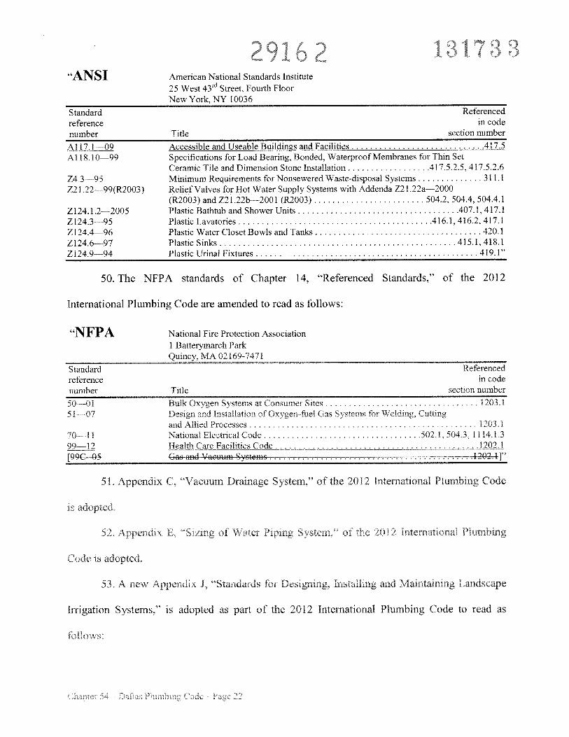
“ANSI American National Standards Institute25 West 43rd Street, Fourth FloorNew York, NY 10036
Standard Referencedreference in codenumber Title section number
Al 17.l—09 Accessible and Useable Buildings and Facilities 417.5A118.l0—99 Specifications for Load Bearing. Bonded, Waterproof Membranes for Thin Set
Ceramic Tile and Dimension Stone Installation 4175.2.5.41 7,5.2.6Z4.3— 95 Minimum Requirements for Nonsewered Waste-disposal Systems 311.1721 .22—99(R2003) Relief Valves for Hot Water Supply Systems with Addenda Z21,22a—2000
(R2003) and Z21.22b—200l (R2003) 504.2, 504.4, 504.4.1Z124. 1 .2—2005 Plastic Bathtub and Shower Units 407.1, 417.1Zl24.3—95 Plastic Lavatories 416.1, 416.2, 417.1Z124.4—96 Plastic Water Closet Bowls and Tanks 420.1Z124.6—97 Plastic Sinks 415.1, 418.1Z124.9—94 Plastic Urinal Fixtures 419.1”
50. The NFPA standards of Chapter 14, “Referenced Standards,” of the 2012
International Plumbing Code are amended to read as follows:
“NFPA National Fire Protection Association1 Batterymarch ParkQuincy. MA 02 169-7471
Standard Referencedreference in codenumber Title section number
50 01 Bulk Oxygen Systems at Consumer Sites 1203.151 07 Design and Installation of Oxygen fuel Gas Stems for Welding. Cutting
and Allied Processes . . . . . 1203.170 11 National Electrical Code , 502.1. 504 3, 1 1 14.1.399—12 Health Care Facilities Code 1202.1[99C 05 Gas and Vacuum Systems
51 Appendix C, “Vacuum Drainage System,” of the 2012 International Plumbing Code
dix F’. ‘Siz g t 1 012 Interna o
Code is adopted.
53. A new Appendix J. ‘Standaids iOr Designing. installing and Maintaining Landscape
Irrigation Systems,” is adopted as part of the 2012 International Plumbing Code to read as
foilov’
:
29162 i31;3“APPENDIX J
STANDARDS FOR DESIGNING, INSTALLINGAND MAINTAINING LANDSCAPE IRRIGATION SYSTEMS
SECTION JiOlSCOPE AND PURPOSE
J1O1.1 Scope. This appendix applies to the installation, alteration, repairs, relocation,replacement. addition to, use or maintenance of irrigation systems within the city. This appendixregulates the installation of backflow prevention devices, control valves, automatic irrigationcontrollers, control wiring and water conservation required for the proper design, installation andoperation of irrigation systems. All irrigation systems must comply with the provisions of thisappendix and with 30 Texas Administrative Code Chapter 344.
J1OL2 Purpose. The purpose of this appendix is to require all irrigation systems to be designed,installed, maintained, altered, repaired, serviced and operated in a manner that will promotewater conservation.
SECTION J102DEFINITIONS
J102.l Definitions. The following words and terms shall have the meanings shown herein:
iRRIGATION SYSTEM. An assembly of component parts that is permanently installed for thecontrolled distribution and conservation of water to irrigate any type of landscape vegetation inany location, reduce dust or control erosion. This term does not include a system that is used onor by an agricultural operation as defined by Section 251.002 of the Texas Agriculture Code.
IRRIGATION TECHNICIAN. A person who works under the supervision of a licensedirrigator to instaH, maintain, alter, repair, service or supervise installation of an irrigation system,including the connection of such system in or to a private or public, raw or potable water supplysystem or any water supply, and who is required to be licensed under this ordinance or 30 TexasAdministrative Code Chapter 344.
MAINTENANCE, ALTERATION, REPAIR OR SERVICE. Any activity that involvesopening the irrigation main line to the atmosphere at any point prior to the discharge side of anyirrigation zone control valve. This includes, but is not limited to. repairina or connecting into amain supply pipe, replacing a zone control valve or repairing a zone control valve in a mannerthat opens the system to the atmosphere.
TCEQ. Texas Commission on Environmental Quality.
WATER CONSERVATION. The design, installation, service and operation of an irrigationsystem in a manner that prevents the waste of water, promotes the most efficient use of water,and applies the least amount of water that is required to maintain healthy individual plantmaterial or turf, reduce dust and control erosion.
9 61) (j
SECTION J103DESIGN OF THE IRRIGATION PLAN
J103.1 Minimum standards for the design of the irrigation plan.
J103.l.I Irrigation plan. A licensed irrigator or landscape architect shall prepare an
irrigation plan for each site where a new irrigation system will be installed. A city approved
irrigation plan must be on the job site at all times during the installation of the irrigation
system. A drawing showing the actual system installation must be provided to the irrigation
system owner on completion of the installation. During installation, variances from the
original plan may be authorized by the licensed irrigator if the variance from the plan does
not:
I. Diminish the operational integrity of the irrigation system;
2. Violate any requirements of this ordinance or 30 Texas Administrative Code Chapter
344; and
3. Go unnoted in red on the irrigation plan.
J103.1.2 Coverage area. The irrigation plan must include complete coverage of the areas to
be irrigated; areas not irrigated must be noted on the irrigation plan.
J103.1.3 Plan requirements. All irrigation plans used for irrigation system installation must
be drawn to scale. Two sets of irrigation drawings must be submitted, one set to be retained
as part of the inspection records, the other set is required for onsite inspection and must he
given to the property owner on completion of the irrigation system. Submitted irrigation
plans must have a minimum font size of 332”. a maximum drawing sheet size of 36” X 48”
and must include the following information:
l. the dated seal and signature of either a licensed irrigator or a landscape architect:
Exceptions:
i. ot requirea or pi peri nat i oiiu ane cuji d s a pc nshomestead.
2 ot required for irrigation plans submitted by a licensed and registered
plumbing contraciui
2. all major physical features and the boundaries of the area to be watered:
3 north arrow;
, _)
2Q11JLL)
5. the zone flow measurement for each zone:
6. location and type of each:
6.1. controller;
6.2. rain and freeze sensors:
6.3. all electrical splices; and
7. location, type, and size of each:
7.1. water source, such as, but not limited to a water meter and point(s) ofconnection;
7.2. backflow prevention device;
7.3. water emission device, including, but not limited to, spray heads, rotarysprinkler heads. quick-couplers, bubblers. drip or micro-sprays;
7.4. valve. including, but not limited to, zone valves, station solenoid valves,automatic master valves and isolation valves;
7.5. pressure regulation components;
7,6, main line and lateral piping:
7.7. scale used; and
7.8. design pressure.
SECTION J104DESIGN AND INST LLATION
J 104 1 1 nimum design and is allation requirements
J104.L1 Backf1o protection. Any irIigation \vStCh connected to a puO1c or prRatepotable water system be connected through a TcEQ-approved backfiow preventionmethod. The hackflow pre ention device must he approved by the American Society ofSanitary Engineering or the Foundation for Cross-Connection Control and HydraulicResearch at the University of Southern California, the Umjrm Plumbing code, the DallasPlumbing Code or a city-approved laboratory that has equivalent capabilities for both thelaboratory and field evaluation of backflow prevention assemblies. Backfiow preventiond e must be installed v ccordance with the lab ator appnnal standard or if the
I dees i o ‘ni. c irie I o e, 11w H ni II
I )Iüi ) )
12J104.1.1.1 Backflow device installation. Connections between the potable water supply
and the approved backflow preventer must be of the same type of material and joining
method as required by the Dallas Plumbing Code and Dallas One- and Two-Family
Dwelling Code. The backflow device must be installed a maximum of 10 feet from the
water meter on the property being served by the irrigation sstem. Backflow devices may
not be installed in the parkway (between the sidewalk and the public right-of-way.)
Exceptions:
1. Atmospheric vacuum breakers must be installed in an accessible location.
2. Backflow devices may be installed in the public right-of-way or at a distancegreater than 10 feet from the water meter or potable water supply with priorapproval from the building official.
J104.1.1.2 Approved types of backflow devices. The following types of backflow
devices are approved:
1. Air gap.
2. Atmospheric vacuum breaker (AVB).
3. Pressure vacuum breaker (PVB).
4. Double check backfiow preventer (DCA).
5. Reduced pressure principal backfiow preventer (RPZ)
J104.1.l.3 Double check backflow assembly (DCA). A DCA must be installed andmade accessible by a minimum jumbo valve box (length 26 inches X 19 inches) or larger.
J104.1.1.3.1 Valve box. A valve box must be installed on compacted soil. Rocks.brick or other types of support may not be used. A alve box coer must be installed‘ush with I rish grade nii num cl air gap is cu e betwee the rottom fthe D ami nches n a: roe
J104.1.1.4 Reduced pressure principal backflo preventer (RPZ). n RPZ r1ust hLinstalled according to the manutacturers installation requirements for aboveground
installation and protected irom freezing. Tn dye inches of washed rock must be installed
under the RPZ.
J104.1.2 Isolation valve and y-type strainer. An isolation valve and y-type strainer must beinstalled prior to the double check or reduce pressure principal backflow preventer in anapproved valve box. The isolation valve and y-type strainer must be installed a maximum of24 inches from the installation of the double check or reduced pressure principal backflowpreventers.
J104.2 Limitation. No irrigation design or installation may require the use of any component,including the water meter, in a way which exceeds the manufacturer’s published performancelimitations for the component.
J104.3 Emission devices.
J104.3.1 Emission devices. The maximum spacing between emission devices must notexceed the manufacturer’s published radius or spacing of the device(s). The radius or spacingis determined by referring to the manufacturer’s published specifications for a specificemission device at a specific operating pressure.
J104.3.2 Aboveground spray. New irrigation systems may not utilize aboveground sprayemission devices in landscaped areas that are less than 60 inches in width or length notincluding impervious surfaces which contain impervious pedestrian or vehicular trafficsurfaces, along two or more perimeters. If pop-up sprays or rotary sprinkler heads are used ina new irrigation system, the sprinkler heads must direct flow away from any adjacent surfaceand may not be installed closer than four inches from a hardscape, such as, but not limited to,a building foundation, fence, concrete, asphalt, payers or stones set with mortar.
Exception: Narrow paved walkways, jogging paths, golf cart paths or other small areaslocated in cemeteries, parks, golf courses or other pubhu areas may be exempted fromthis requirement if the runoff drains into a landscaped area.
J1O433 Water pressure. Emission devices must be installed to operate at the minimum andnot above the maximum sprinkler head pressure as published by the manufacturer for thenozzle and head spacing that is used. Methods to achieve the water pressure requirementsinclude, but are not limited to, flow control valves a pressure regulator or pressureompcnsating pray heads
J1O44 Misting i g must be kept C ed as an rnc b d (undco’ er
J104.5J Velocity. Piping in irrigation systems must be designed and installed so that theflow of water in the pipe will not exceed a velocity of 5 feet per second for polyvinylchloride (PVC) pipe or exceed the manufacturer’s recommendation for other piping materials.
29 62J104.5.2 PVC pipe primer solvent. All new irrigation systems installed using PVC pipe andfittings must be primed with a colored primer prior to applying the PVC cement inaccordance with the Dallas Plumbing Code and the Dallas One-and Two-Family DwellingCode.
J104.5.3 Depth coverage of piping. Piping must be installed to provide a minimum depthcoverage of 6 inches of select backfill between the top of the pipe and the natural grade of thetopsoil. All portions of the irrigation system that fail to meet this standard must be noted onthe irrigation plan. If the area being irrigated has rock at a depth of 6 inches or less, selectbackfill may be mounded over the pipe. Mounding must be noted on the irrigation plan anddiscussed with the irrigation system owner or owner’s representative to address any safetyissues. All trenches and holes created during installation of an irrigation system must bebackfilled and compacted to the original grade. Mechanical excavation is not allowed wheredamage could occur to a tree root system per Section 5lA-lO.136 of the Dallas DevelopmentCode.
Exception: If a utility, man-made structure or roots create an unavoidable obstacle whichMakes the 6 inch depth coverage requirement impractical, the piping must be installed toprovide a minimum of 2 inches of select backfill between the top of the pipe and thenatural grade of the topsoil.
J104.6 Irrigation zones. Irrigation systems must have separate zones based on plant materialtype, microclimate factors, topographic features, soil conditions and hydrological requirements.Zones must be designed and installed so that all of the emission devices in that zone irrigate atthe same precipitation rate.
J104.7 Spray over impervious surfaces prohibited. Irrigation systems must not spray waterover surfaces made of concrete, asphalt, brick, wood, stones set with mortar or any otherimpervious material, such as, but not limited to. walls, fences, sidewalks, streets. etc.
J104.8 Master valve. A master valve must be installed on the discharge side of the backflowprevention device on all flew installations in an approved valve box.
J1O49 Rain and freeze shut-off devices All automatically controlled irrigat on sy tems mustr c udc s nso or ot er hno ogy designed to nhibit or i en pt peratior of he rr gation
wstem dun g period f oisturc n all or fr c rg tempc at es. Ran iroistui a neezeshutoff technology must he mctalled according to the manutacturers pjhhshedrecommenuanons, All existing automatic rrgat1on su5!em5 mUst iflCiuuc a suioi or oihrtechnology desianed to inhibit or interrupt operation of the irrgaf/on svsfern during periods ofmoisture rainfall or temperatures of3i’ orhelow
131 t3:3t_ I L
J104.1O Valves. All new irrigation systems and major maintenance, alterations, repairs orservice, including repair or replacement of the backflow device, must include an isolation valveand y-type strainer between the water meter and the backflow prevention device. A master valvemust be installed after the backflow preventer. Zone valve(s), station solenoid valve(s), anautomatic master valve and isolation valves must be installed in an approved valve box foraccessibility, repair and service.
J104.11 Irrigation system wiring.
J104.l1.1 Underground electrical wiring. Underground electrical wiring used to connectan automatic controller to any electrical component of the irrigation system must be listed byUnderwriters Laboratories as acceptable for direct underground burial.
J104.1l.2 Component wiring size. Electrical wiring that connects any irrigation systemelectrical components must be sized according to the manufacturer’s recommendation.
J104.1l.3 Wire splicing. Electrical wire splices which may be exposed to moisture must bewaterproof as certified by the wire splice manufacturer. Electrical splice locations must benoted on the irrigation plan.
J104.1 1.4 Automatic controller wiring. Underground electrical wiring that connects anautomatic controller to any electrical component of the irrigation system must be buried witha minimum of 6 inches of select backfill.
J104.1 1.5 Exposed wiring. All exposed wiring must be protected from physical damage incompliance with the Dallas Electric Code.
Exception: Listed cord and plug.
J104.12 Non-potable water. Water contained within the piping of an irrigation system isdeemed to be non-potable. No drinking or domestic water usage, such as, but not limited to,filling swimming pools or decorative fountains. may be connected to an irrigation system. If ahose bibb (an outdoor water faucet that has hose threads on the spout) is connected to anIrrigation system for the purpose of providing supplemental water to an area, the hose bibb mustne ilistaliLd u’ing a quick coupler kes u’ a quick Lodpier ‘ustalled in a LU red purple’ ahe boAanu ifle hose own 11iu aIlS noses eoiuieteu to use viny IIIUSI vu aueicu iaois-puuauLc. not snie 101
drinking n isolation salve must be installed upstream ot a quick coupler connecemg a hosebihb to an ii Ii2Ut;un i Ih.
J104.13 Check valves. Check valves are required where des ation differences may result in losshead drainage. Check salves may be located at the sprinkler head(s) or on the lateral lines.
J104.14 Direct supervision. Job site supervision is required by either a licensed irrigator orirrigation technician while work is being performed. When a licensed irrigator is not onsite, thelicensed irrigator shal b e r r a that a licensed irrigati r c n
ft supers is the Inst ha
J104.15 Programmable irrigation controller. All new irrigation system installations requirethe installation of a programmable irrigation controller. The programmable irrigation controllermust be equipped with an emergency back-up power supply in the event of a primary powerfailure.
J104.15.1 Manufacturer’s instructions. A programmable irrigation controller must beinstalled according to the manufacturer’s installation instructions.
J104.15.2 Maximum height. A programmable irrigation controller may not be mountedmore than 60 inches above a level floor surface.
J104.15.3 Power surges. The electrical power supplying a programmable irrigationcontroller must be protected from power surges or utilize a dedicated electrical circuit.
J104J5.4 Minimum installation distance. A programmable irrigation controller must beinstalled at least 15 inches from center to any side wall or similar obstruction.
Exception: When the manufacturer’s installation instructions require a lesser distance.
SECTION J105COMPLETION AND MAINTENANCE
J105.1 Completion of irrigation system installation.
J105.1,1 Completion. The licensed irrigator, installer or technician shall complete thefollowing items upon completion of the irrigation system installation:
1 A final “walk through” with the irrigation system s owner or the owner’srepresentative to explain the operation of the system.
2. A maintenance checklist with the signature of the irrigation system owner orowner’s representative and signed, dated and sealed by the licensed irrigator, installeror technician, If the irrigation 5ystem’s owner or owner’s representative is unwillingor unable to sign the maintenance checklist, the irrigator shall note the time and date)f the efusa on the irrigat o sy tern ner own i’s representative’s signature
1 e ig lion system ov r yr r c ta 1 1 be gi en the onginar nte a e checklist and a d 1’ op o Fe m ai’e checklist shall b
mair ta ed y tne licensed imga or he te r n he ia itenance checkilsi musinclude but are not limited to:
2.1. The manufacturer’s manual for the automatic controller.
2.2. A seasonal (spring. summer, fall, winter) watering schedule based on eithercurrent/real time evapotranspiration or monthly historical referencee apotransplratlon (historical ET) data. monthly effecrvc rainfall estimates,
7:33
2.3. A list of components, such as the nozzle or pump filters, and other suchcomponents that require maintenance and the recommended frequency for theservice.
3. A permanent sticker which contains the licensed irrigator’s name, license number,company name, telephone number and the dates of the warranty period affixed toeach programmable irrigation controller installed by the licensed irrigator, installer ortechnician. If the irrigation system is manual, the sticker must be affixed to theoriginal maintenance checklist. Programmable irrigation controllers listed andinstalled for outdoor installation require a water proof permanent sticker. Theinformation contained on the sticker, whether indoor or outdoor, must be printed withwateqroof ink.
4. Provide the irrigation system’s owner or owner’s representative a copy of theirrigation plan indicating the actual system installation.
5. The statement, “This irrigation system has been installed in accordance with allapplicable state and local laws, ordinances, rules, regulations or orders. I have testedthe system and determined that it has been installed according to the irrigation planand is properly adjusted for the most efficient application of water at this time.”
6. Provide a certificate of compliance to the building official and the property owner orthe property owner’s representative stating that the requirements of this section and 30Texas Administrative Code Chapter 344 have been completed.
J105.2 Maintenance, alteration, repair or service of irrigation systems.
J105.2J Irrigator responsibility. The irrigator is responsible for all work that the irrigatorperformed during the maintenance, alteration, repair or service of an irrigation sys’temduring the warranty period. The irrigator or business owner is not responsible for theprofessional negligence of any other irngator who subsequently conducts any irrigationservice on the same irrigation system
J10 22 Irenches and holes A trenches arr l e cated during te a nt nanceii rat ir. repair or ser ice o n irrigation srcr m m s t e returned to the & nal gradeith ompacted select backfill
J105.2.3 PVC primer. Colored PVC pIpe pnmer solient must be used on all pipes andfittings used in the maintenance alteration repair or ceri’ice of an irrigation svcteni inaccordance with the Dallas Plumbing Code or Dallas One- and Two-Family Dwelling Code.
J105.2.4 Maintenance, alteration, repair or service. When maintenance, alteration, repairor service of an irrigation system is reiuired and performed and an isolation vali e. v-typest- icr, rain and freeze sens $ or approred backflo deuce are not OreseIl e ualxe(s)
sers nus be i nnitted ested ed Exi t ig p kflouu
SECTION J106RECLAIMED WATER OR WATER WELLS
3106.1 Reclaimed water or water wells. Reclaimed water, storm water, gray water or waterwells may be utilized in landscape irrigation systems.
J106.1.1 Connections. An irrigation system utilizing reclaimed water, storm water, graywater or well water must not be directly connected to the potable water supply.
Exception: When potable water is protected by an air gap as defined by and installed inaccordance with the Dallas Plumbing Code per the Dallas One- and Two-FamilyDwelling Code.
3106.1.2 Edible crops. Water from an irrigation system utilizing reclaimed water, stormwater, gray water or well water may not make direct contact with edible crops, unless thecrop is pasteurized before consumption.
J106.1.3 Property lines. An irrigation system utilizing reclaimed water, storm water, graywater or well water must not spray water across property lines that do not belong to theirrigation system ‘s owner.
J106.1.4 Purple components. An irrigation system utilizing reclaimed water, storm water.gray water or well water must be installed using purple components as detailed in the DallasPlumbing Code per the Dallas One- and Two-Family Dwelling Code.
J106.1.5 Sign. A minimum of an 8 inch by 8 inch sigu with purple background and whiteletters must be prominently posted in the area that is being irrigated utilizing reclaimedwater, storm water, gray water or well water, that reads, “RECLAIMED WATER - DO NOlDRINK” and “AGUA DE RECUPERACION - NO BEBER.”
J106.L6 Backflow prevention. Backflow prevention on the reclaimed water supply linemust be in accordance with the Dallas Plumbing Code, Dallas One- and Two-FamilyDii cuing (ode, and Dallas Water Utilities rules and regulations
e ces A L the 2 r Plumb r
adopted
55. All chapters of the 2012 Imernatienal Plumbinu Code adopted by this ordinance are
subehapters of Chapter 54 of the Dallas City Code, as amended.
1 ‘31 ‘341fr-’
56. All references in the 2012 International Plumbing Code to the fire code, building
code, mechanical code, electrical code, residential code, existing building code, energy
conservation code, and fuel gas code refer, respectively, to Chapters 16, 53, 55. 56, 57, 58, 59,
and 60 of the Dallas City Code.
SECTION 2. That a person violating a provision of this ordinance, upon conviction, is
punishable by a fine not to exceed $2,000. No offense committed and no liability, penalty, or
forfeiture, either civil or criminal, incurred prior to the effective date of this ordinance will be
discharged or affected by this ordinance. Prosecutions and suits for such offenses, liabilities,
penalties, and forfeitures may be instituted, and causes of action pending on the effective date of
this ordinance may proceed, as if the former laws applicable at the time the offense, liability,
penalty, or forfeiture was committed or incurred had not been amended, repealed. reenacted, or
superseded, and all former laws will continue in effect for these purposes.
SECTION 3. That Chapter 54 of the Dallas City Code, as amended, will remain in full
force and effect. save and except as amended by this ordinance. An existing structure, system.
development project, or registration that is not required to come into compliance with a
requirement of this ordinance will be governed by the requirement as it existed in the former law
last applicable to the structure, system, development project, or registration. and all former laws
w I ontinu in eff for t purp s
S C O\ Fh tc and i51 f rdi e a era and
goerned by Section l4 of Chapter 1 of the Dallas City (‘ode. as amended
31 3.‘ - 8 /
SECTION 5. That this ordinance will take effect on November 1, 2013, and it is
accordingly so ordained.
APPROVED AS TO FORM:
WARREN M. S. ERNST, Interim City Attorney
By)
___
sistant City Attorney
Passed SEP 2 5 2013

For a Copy of the exhibitPlease contact
The City Secretary’s Office