
ORDER · Site Selection ... 310. Antenna Installation ... knowledge of the dangers involved. Work...
164
ORDER 6750.54 ELECTRONIC INSTALLATION INSTRUCTIONS FOR INSTRUMENT LANDING SYSTEM (ILS) FACILITIES December 17, 1993 U.S. DEPARTMENT OF TRANSPORTATION FEDERAL AVIATION ADMINISTRATION Distribution: A-W (NWAS/SM/SE)-3; A-Z (CD)-3, Initiated By: ANN-400 A- FAF-O (Ltd)
Transcript of ORDER · Site Selection ... 310. Antenna Installation ... knowledge of the dangers involved. Work...

ORDER 6750.54
ELECTRONIC INSTALLATION INSTRUCTIONS
FOR INSTRUMENT LANDING SYSTEM (ILS)
FACILITIES
December 17, 1993
U.S. DEPARTMENT OF TRANSPORTATION FEDERAL AVIATION ADMINISTRATION
Distribution: A-W (NWAS/SM/SE)-3; A-Z (CD)-3, Initiated By: ANN-400 A-FAF-O (Ltd)

FAA Form 1320-5 (6.80) USE PREVIOUS EDITION
RECORD OF CHANGES DIRECTIVE NO. 6750.54
CHANGE TO BASIC
SUPPLEMENT OPTIONAL
CHANGE TO BASIC
SUPPLEMENTS OPTIONAL

(and ii)
FOREWORD
The material in this order is the result of a headquarters/regional group effort to consolidate and update a number of existing Instrument Landing Systems (ILS) orders that are outdated. This order identifies some new localizer antenna arrays. Also added in this order is information on the end-fire glide slope antenna system. Additional material has been added through the regional participants, based on their experience in installing ILS's.
Rodman Gill Program Director for Navigation and Landing


1 2 / 1 7 / 9 3 6750.54
TABLE OF CONTENTS Page
CHAPTER 1. GENERAL INFORMATION ...................................................................................................
................................................................................................................................................................1
Paragraph
1. Purpose ...................................................................................................................................... 2. Distribution ................................................................................................................................. 3. Cancellation ................................................................................................................................ 4. Application ................................................................................................................................. 5. Directive Verbs ........................................................................................................................... 6. Procedures .................................................................................................................................. 7. Description of Operational Components ....................................................................................
Table 1-1. Frequency Allocation in MHz .................................................................................... 8. RF Connectors ............................................................................................................................
Figure 1-1. Assembly of UG-1185 Connector ............................................................................. Figure 1-2. Assembled UG-1185 Connector ...............................................................................
9. Flight Inspection .........................................................................................................................
CHAPTER 2. LOCALT7.RR SYSTEMS ...................................................................................................9
SECTION 1. TECHNICAL CHARACTERISTICS ............................................................................9
System Description ......................................................................................................................................9 Localizer Transmitting Equipment ..............................................................................................................9 Figure 2-1. Typical Localizer Transmitter .................................................................................................10 Signal Cabling ...........................................................................................................................................11 Localizer Antenna Systems .......................................................................................................................11 Figure 2-2. V-Ring Antenna ......................................................................................................................13 Figure 2-3. Single V-Ring Radiation Pattern .............................................................................................14 Figure 2-4. 15-Element V-Ring Composite Radiation Pattern ..................................................................15 Figure 2-5. 15-Element V-Ring Array .......................................................................................................16 Figure 2-6. 8-Element V-Ring Array .........................................................................................................17 Figure 2-7. 8-Element V-Ring (Once-Frequency) Localizer Antenna Array ............................................18 Figure 2-8. Traveling Wave Antenna Vertical Radiation Pattern ..............................................................19 Figure 2-9. Typical Ground-Mounted Traveling Wave Array-Type I .......................................................21 Figure 2-10. LPD Antenna .........................................................................................................................22 Figure 2-11. Log Periodic Dipole Antenna Radiation Pattern ...................................................................23 Figure 2-12. Wide and Narrow Aperture Localizer Antenna Arrays ........................................................24 Figure 2-13. 8-&14-Element LPDA Radiation Patterns,
1 1 1 1 1 1 3 4 77 8 8
200. 201.
202. 203.

6750.54 1 2 / 1 7 / 9 3 Antenna Spacing, Phase & Amplitude ...........................................................................25

1 2 / 1 7 / 9 3 6750.54
iv
Paragraph Page
Figure 2-14. 8-Element LPDA (One-Frequency) Localizer Antenna Array .. Figure 2-15. 14-Element LPDA (One-Frequency) Localizer Antenna Amy .. Figure 2-16. 14/6 Dual Frequency LPD Array Spacing and Distribution .... Figure 2-17. 14/6 Dual Frequency Course Radiation Pattern (CSB + SBO) .. Figure 2-18. 14/6 Dual Frequency Antenna Clearance Radiation Pattern (CSB
................ 26
................ 27................. 28.................29
+ SBO) 30
204. Integral Monitoring ................................................................................................
205.-208. Reserved .........................................................................................................
SECTION 2. ELECTRONIC INSTALLATION ........................................................... 209. Purpose ................................................................................................................... 210. General ................................................................................................................... 211. Tune Up Procedures ............................................................................................... Figure 2-19. RF Transmission Path Length Test Setup and Distribution ....................... Figure 2-20. Monitor Path Length Test Setup (Vector Voltmeter) ................................ 212. Flight Inspection ..................................................................................................... 213.-216. Reserved .........................................................................................................
CHAPTER 3. GLIDE SLOPE ....................................................................................................................53
SECTION 1. TECHNICAL CHARACTERISTICS ...........................................................................53
300. System Description ....................................................................................................................................................................................................................................... 53 301. Glide Slope Transmitters ..................................................................................................................................................................................................................... 53
302. RF Coa
xial Transmission Lines .............................................................................................................................................................................................................................................. 53 303. Glide Slope Antenna Systems ...................................................................................................................................................................................................... 53
54 55 57
Sideband-Reference Glideslope ............................................................................................................................................... ...........................................................................................................................58
Figure 3-5. Sideband Reference Distribution/Recombination Circuits ...................................................................... .....................................................................................................................................................59 Figure 3-6. Carrier and Sideband Vertical Lobe Structure for
Figure 3-1. Vertical Lobe Structure For Null-Reference Glide Slope ................... ......Figure 3-2. Null Reference Monitor Circuitry (Typical) ....................................... ...... Figure 3-3. Figure 3-4.
Vertical Lobe Structure for Sideband-Reference Glide Slope ......Composite Vertical Lobe Structure (Sideband Patterns) for
......

6750.54 1 2 / 1 7 / 9 3
v
Capture Effect Glide Slope ............................................................................................................................................................. .....................................................................................................................................................60 Figure 3-7. Clearance Signal Vertical Lobe Structure for Capture Effect
Glide Slope .................................................................................................................................................................................................... .....................................................................................................................61
Figure 3-8. Composite Vertical Lobe Structure for Capture Effect Glide Slope .......................62

1 2 / 1 7 / 9 3 6750.54
v
Paragraph Page
Figure 3-9. Typical Capture-Effect Glide Slope Recombination Circuit ................................. 63 Figure 3-10. Vertical Patterns, End-Fire Array ......................................................................... 65 Table 3-1. Glide Slope Comparisons ........................................................................................ 66 Figure 3-11. Typical EFGS RF Distribution and Monitoring ............................................... 67
304.-308. Reserved .............................................................................................................................. 67
SECTION 2. ELECTRONIC INSTALLATION ................................................................................68
309. Site Selection ........................................................................................................................... 68 310. Antenna Installation ................................................................................................................. 68 311. Transmission Lines .................................................................................................................. 68 312. Initial Tuneup/Setup for Null Reference Facilities ................................................................ 69
Table 3-2. Antenna and Offset for Null-Reference System for Level Terrain ......................... 70 Table 3-3. Antenna Offset (Multiplying Factor) ....................................................................... 71
313.-317. Reserved .............................................................................................................................. 74 318. Tuneup for Sideband Reference Facilities ................................................................................ 74
Table 3-4. Antenna and Offset for Sideband Reference System ............................................. 75 Table 3-4A. Antenna Offset (Multiplying Factor) .................................................................... 76 Table 3-5. Antenna Settings for 4 to 1 USB to LSB Null Ratio
(For Level Terrain) ............................................................................................................... 77 Table 3-6. Antenna Settings for 2.5 to 1 USB to LSB Null Ratio
(For Level Terrain) ............................................................................................................... 78 Table 3-7. Calculation of USB and LSB Nulls and Antenna Heights ........................................ 79
319. Far-Field Ground Phasing ........................................................................................................80 320. Location of the Phasing Detector ............................................................................................. 81 321. Flight Inspection ....................................................................................................................... 82 322. Tuneup/Setup for Capture Effect Facilities .............................................................................
...................................................................................................................................................84 Table 3-8. Antenna Height and Offset for Capture Effect System
(For Level Terrain) ................................................................................................................. 84 Table 3-8A .................................................................................................................................. 85
323. Flight Inspection ....................................................................................................................... 88 324.-328. Reserved .............................................................................................................................. 89 329. Tuneup/Setup for End-Fire Facilities ........................................................................................ 90
Figure 3-12. Antenna Curvature Computation ........................................................................91 Figure 3-13. Regarding Azimuth Coverage ............................................................................... 92
330.Flight Inspection ........................................................................................................................... 93 331.-333. Reserved .............................................................................................................................. 94

1 2 / 1 7 / 9 3 6750.54
vi
6750.54
Page
CHAPTER 4. MARKER TECHNICAL DETAILS ....................................................................................95
400. Introduction ...............................................................................................................................95 401. Location of the ILS Markers .....................................................................................................95 402. Transmit System ........................................................................................................................95
Table 41 . Marker Indicator Key ...............................................................................................95 403. RF Coaxial Transmission Lines ................................................................................................96 404. Antenna Patterns .......................................................................................................................96 405. Antenna Mounting Heights .......................................................................................................96
Figure 41 . Major and Minor Axis ............................................................................................96 Figure 4-2. Required Signal Strength and Coverage .................................................................97 Figure 43. Coverage vs. Height Above Marker ........................................................................98
406. Marker Beacon Adjustments and Flight Inspections ................................................................98
CHAPTER 5. COMPASS LOCATOR SYSTEMS ........................................................................................
..............................................................................................................................................................99
SECTION 1. TECHNICAL CHARACTERISTICS
500. System Description ..................................................................................................................99
SECTION 2. INSTALLATION INSTRUCTIONS .........................................................................101
501. Purpose ...................................................................................................................................101 502. General ...................................................................................................................................101 503.-504. Reserved ...........................................................................................................................101
CHAPTER 6. OTHER INFORMATION ..................................................................................................103
SECTION 1. TECHNICAL CHARACTERISTICS ........................................................................103
600. Remote Monitor and Control .................................................................................................103 601. Remote Maintenance Monitoring .........................................................................................103 602. ILS Interlock Systems ............................................................................................................104 603. Far-Field Monitor ..................................................................................................................104 604.-613. Reserved ...........................................................................................................................104
SECTION 2. ELECTRONIC INSTALLATION .............................................................................105
614. General ................................................................................................................................... 105615. Equipment Layout and Installation ........................................................................................ 105616. Remote Monitor and Control ................................................................................................. 105

1 2 / 1 7 / 9 3 6750.54
vii
617. Remote Maintenance Monitoring ........................................................................................... 106618. ILS Interlock Systems ............................................................................................................ 106

vii
Page APPENDIX 1. MULTIPLE ILS INTERLOCK SYSTEMS ..........................
Paragraph
1. General ............................................................................................................................................1 2. Equipment Description ....................................................................................................................1 3. ILS System Requirements ...............................................................................................................2
Figure 1. Interlock System Diagram ..................................................................................................2 4. Technical Description ......................................................................................................................3
Figure 2. Selector/Indicator Block Diagram ....................................................................................3 Figure 3. Control Unit Block Diagram ...............................................................................................4
5. System Installation .........................................................................................................................5 Figure 4. Installation Wiring Table ..................................................................................................6 Figure 5. Multiple ILS Interlock Selector/Indicator Schematic Diagram
(Sheet 1 of 2) ................................................................................................................7 Figure 6. Multiple ILS Interlock Selector/Indicator Schematic Diagram
(Sheet 2 of 2) ................................................................................................................8 Figure 6A. Multiple ILS Interlock Control Unit (FA-9427/2)
Schematic Diagram .................................................................................................9 Figure 6B. +12 V DC Power Supply Schematic ...............................................................................9 Figure 7. Mark IA (Wilcox) ILS (Localizer and Glide Slope)
Schematic Diagram ....................................................................................................10 Figure 8. Mark 1B (AIL) ILS (Localizer and Glide Slope)
Schematic Diagram ....................................................................................................11 Figure 9. Mark IC (Wilcox) ILS (Localizer and Glide Slope)
Schematic Diagram ....................................................................................................12 Figure 10. Mark ID (Wilcox) ILS (Localizer and Glide Slope)
Schematic Diagram .................................................................................................13 Figure 11. AN/GRN-27 (T.I. CAT II) ILS Localizer and Glide Slope
Schematic Diagram .................................................................................................14 Figure 12. FA-5791 ILS Solid-State 75 MHz Marker Schematic Diagram ................................... 15 Figure 13. Mark IA (Wilcox) ILS 75 MHz Marker FA 8030-3
Schematic Diagram ............................................................................................... 16 Figure 14. FA-8102, 3, and 4 ILS 75 MHz Marker Schematic Diagram ....................................... 17 Figure 15. Mark 1B (AIL) ILS 75 MHz Markers (FA-8603, 61, and 62)
Schematic Diagram ..............................................................................................................18 Figure 16. Mark lC (Wilcox) ILS 75 MHz Markers (FA-8831-6)
Schematic Diagram ..............................................................................................................19 Figure 17. AN/GRN-28 (Texas Instruments) ILS 75 MHz Marker
Schematic Diagram .................................................................................................................20 Figure 18. AN/GRN-26 (Texas Instruments) ILS 75 MHz Marker
Schematic Diagram .............................................................................................. 21


12/17/93 6750.54
CHAPTER 1. GENERAL INFORMATION
1. PURPOSE. This order sets forth national installation procedures and standards for use by technical personnel working on ILS equipment. In as much as uniform operating characteristics should be obtained for all facilities, it is necessary that standard installation, tuneup, and maintenance procedures be followed by all personnel. Personnel assigned the responsibility of installing and adjusting the ILS facilities should be skilled personnel who have been trained in proper installation techniques.
2. DISTRIBUTION. This order is being distributed to branch level in the offices of the Program Director for Navigation and Landing and Airport Safety and Standards; and the Systems Maintenance and NAS System Engineering Services; branch level in the Engineering, Research and Development Service at the FAA Technical Center; limited distribution to regional Airway Facilities field offices having localizer and glide slope facilities.
3. CANCELLATIONS. The f o l l o w i n g o r d e r s a r e c a n c e l e d :
a. Order 6750.6B, Installation Instructions for Category I and Category II ILS Glide Slopes dated July 9, 1976.
b. Order 6750.35, Installation Instructions for Category I ILS Localizer, Marker Beacon, and Compass Locator Facilities, dated November 14, 1976.
4. APPLICATION. This order applies to new establishments or relocated facilities.
5. DIRECTIVE VERBS. The material in this order contains recommended practices, and other guidance material, which requires the use of certain directive verbs such as SHALL, SHOULD, WILL and MAY. In this order the meaning of the verbs is as follows:
a. SHALL. Action is mandatory.
b. SHOULD. Action is desirable or recommended.
c. WILL. Action is to be taken in the future.
d. MAY. Action is permissible.
6. PROCEDURES.
a. Safety. Personnel shall use care in working on ILS equipment, particularly radio transmitters, since the voltages present are dangerous to life. Observance of precautions necessary to avoid electrical shock is the direct responsibility of the individual. No one shall perform work on the equipment without full knowledge of the dangers involved. Work on high voltage circuits should not be attempted by an individual when it is possible to obtain the services of an assistant.
Chap 1 Page 1 Par 1

12/17/93 6750.54
b. Uniformity of Measurements and Procedures. Adjustment procedures used during the initial tuneup of an ILS facility are of vital importance to the installation engineer and to the electronic maintenance personnel. To assure a maximum degree of standardization, the procedures presented in this order should be used by installation personnel.
c. Instruction Books. Instruction books are available for each type of equipment. These instruction books should be referred to for adjustment to specific units. The instruction books shall be kept current to reflect any corrections and additions required by equipment modifications issued by the Washington office. When any modifications to equipment are made, all applicable drawings must be revised. The installation engineer shall not consider the modification of equipment completed until appropriate changes have been made to the instruction books. Up-to-date instruction books shall be provided for all newly commissioned facilities.
d. Standards and Tolerances. The standards and tolerances for ILS are contained in Order 6750.49 Maintenance of Instrument Landing Systems (ILS) Facilities, and the applicable instruction books. Note that for installation purposes the initial tolerances shall apply.
e. Frequency Coordination. Installation personnel should obtain the ILS frequency assignments from the Regional Spectrum Manager.
f. Local FAA Coordination. Installation personnel should acquaint local maintenance and air traffic personnel of their work prior to their arrival at the site. The maintenance office should be given reasonable advance notice of the installation activity so that a liaison may be set up to:
(1) Assure that all materials and equipment are onsite, undamaged by shipment.
(2) Provide for local participation and familiarization with the equipment.
(3) Establish methods for moving about the airfield. Consult regional procedures for additional guidance in this area.
g. Cleanup. The installation sites should be cleared of debris and unused materials after the installation is completed. The shelter and equipment should be cleaned and any touch-up painting required to establish a professional appearance should be applied.
h. Joint Acceptance Inspection (JAI). Upon completion of the installation a JAI should be conducted in accordance with appendix 2 of Order 6030.45, Facility Reference Data File.
i. Notice to Airman (NOTAM). A NOTAM contains general information (except meteorological information) of an urgent nature, affecting the safety of air navigation. The NOTAM's are distributed as rapidly as possible to acquaint pilots with possible hazardous conditions. A NOTAM should be issued prior to commencement of modifications at existing facilities or turn-on at a new installation. At the time of commissioning of a facility, a NOTAM should be issued regarding runway, frequencies, and restrictions of the facility. Order 6750.16, Siting Criteria for Instrument Landing Systems,
Page 2 Chap 1 Par 6

6750.54 12/17/93
outlines specific requirements for the issuance of a NOTAM at an airport equipped with more than one ILS.
j. Related Material. Prior to installation of the ILS equipment, a review of the latest edition of the following publications will enable a better understanding of the theory and practical operation of the ILS.
(1) Order 6030.45, Facility Reference Data File.
(2) ICAO Annex 10, Volume 1 Part 1, Equipment and Systems.
(3) Order 6740.2, Maintenance of Nondirectional Beacon (NDB).
(4) FAR part 77, Objects Affecting Navigable Airspace.
(5) Order AF P 6750.1, Navigational Aids Facilities and Equipment Modification - ILS.
(6) Order AF P 6750.4, Electronic Facility Instructions Navaids, ILS.
(7) Order 6750.16, Siting Criteria for ILS.
(8) Order 6750.49, Maintenance of Instrument Landing Systems (ILS) Facilities.
(9) Order OA P 8200.1, United States Standard Flight Inspection Manual.
(10) Order 6750.36, Site Survey, Selection and Engineering Documentation for ILS and Ancillary Aids.
(11) Equipment Instruction Books.
7. DESCRIPTION OF OPERATIONAL COMPONENTS.
a. General. The ILS consists of three distinct and separate types of facilities: the localizer, the glide slope, and the markers (with or without COMLO's). The localizer and glide slope provide lateral and vertical guidance, available in the airplane in the form of crosspointer indications. The markers indicate to the pilot his/her position over significant positions along the approach.
b. Associated Facilities. Other facilities such as runway visual range (RVR), lighted aids, distance
measuring equipment (DME) and non-directional beacons (NDB) may be part of an ILS. However, this order will not discuss the installation of these in detail.
c. ILS Channel Assignments. Forty channels have been provided for ILS use. The channels and the proper pairing between localizer and glide slope is shown in table 1-1.
Chap 1 Par 6 Page 3

12/17/93 6750.54
TABLE 1-1
FREQUENCY ALLOCATION IN MHz
ILS DME/TACAN
LOCALIZER GLIDE SLOPE CI ~NNEL GROUND-
TO-AIR AIR-TO-
GROUND PULSE CODE
gS
108.10 334.70 18X 979 1042 12
108.15 334.55 18Y 1105 1042 30
108.30 334.10 20X 981 1044 12
108.35 333.95 20Y 1107 1044 30
108.50 329.90 22X 983 1046 12
108.55 329.75 22Y 1109 1046 30
108.70 330.50 24X 985 1048 12
108.75 330.35 24Y 1111 1048 30
108.90 329.30 26X 987 1050 12
108.95 329.15 26Y 1113 1050 30
109.10 331.40 28X 989 1052 12
109.15 331.25 28Y 1115 1052 30
109.30 332.00 30X 991 1054 12
109.35 331.85 30Y 1117 1054 30
109.50 332.60 32X 993 1056 12
109.55 332.45 32Y 1119 1056 30
109.70 333.20 34X 995 1058 12
Page 4 Chap 1 Par 7

6750.54 12/17/93
TABLE 1-1 (Coned)
LOCALJZFR ' GLIDE SLOPE GROUND-
CHANNEL TO-AIR AIR-TO-
GROUND PULSE CODE
1cS
109.75 333.05 34Y 1121 1058 30 109.90 333.80 36X 997 1060 12
109.95 333.65 36Y 1123 1060 30
110.10 334.40 38X 999 1062 12
110.15 334.25 38Y 1125 1062 30
110.30 335.00 40X 1001 1064 12
110.35 334.85 40Y 1127 1064 30
110.50 329.60 42X 1003 1066 12
110.55 329.45 42Y 1129 1066 30
110.70 330.20 44X 1005 1068 12
110.75 330.05 44Y 1131 1068 30
110.90 330.80 46X 1007 1070 12
110.95 330.65 46Y 1133 1070 30
111.10 331.70 48X 1009 1072 12
111.15 331.55 48Y 1135 1072 30
111.30 332.30 50X 1011 1074 12
111.35 332.15 50Y 1137 1074 30
111.50 332.90 52X 1013 1076 12
111.55 332.75 52Y 1139 1076 30
111.70 333.50 54X 1015 1078 12
111.75 333.35 54Y 1141 1078 30
111.90 331.10 56X 1017 1080 12
FREQUENCY ALLOCATION IN MHz (Cont'd)
TLS 17MEITACAN

12/17/93 6750.54
111.95 330.95 56Y 1143 1080 30 Chap 1 Par 6
Page 5

6750.54 12/17/93
d. Localizer. An ILS localizer furnishes horizontal guidance to an aircraft on an approach to an ILS runway. The localizer transmits in the very high frequency (VHF) band, specifically from 108 to 112 MHz. Guidance from the localizer is provided by amplitude modulating a radiofrequency (RF) carrier with two navigation tones (90 Hz and 150 Hz).
e. Glide Slope. An ILS glide slope furnishes vertical guidance to an aircraft on approach to the runway. The glide slope transmits in the ultrahigh frequency (UHF) band, specifically from 328 to 336 MHz. The glide slope also provides its guidance by amplitude modulating an RF carrier with 90 and 150 Hz tones.
f. Marker Beacons. Marker beacons are sited along the approach path to provide an indication of an aircraft's distance from the runway, and to indicate significant points along an instrument approach path. They are low power transmitters operating at 75 MHz with keyed tone modulation. As an approaching aircraft flies through the radiation pattern the signal is detected by a receiver on the aircraft. Information is displayed in the form of flashing lights and a keyed audio tone. In some cases, DME in lieu of an outer marker can be used.
g. Compass Locator (COMLO). The COMLO operates between 190 to 535 KHz in the low frequency band. While not strictly an integral part of the ILS, it may be included at the outer marker or the middle marker when required for approach procedures.
h. ILS Monitor and Control. Existing and future ILS's have several configurations of monitor and control, including some regional designs. Generally, landlines or through the air receivers are used. Through the air receivers provide monitoring capability only, (no control functions) and are generally used for Category I equipment only; Category IUIII equipment use landline configurations and provides monitor and control functions.
i. Status Unit. In addition to the ILS monitor and control unit, a status unit is normally installed in the tower cab. It provides monitor capabilities to assist the air traffic personnel.
j. Remote Maintenance Monitoring (RMM). Some newer equipment designs contain embedded RMM. In addition, some equipment has been modified with an Airport Remote Monitoring System (ARMS) package. The purpose for ILS RMM is to automate and add remote capabilities to the maintenance operations for ILS equipment. RMM does not replace the ILS executive monitor (the monitor which causes equipment shutdown), or the remote status unit normally used by air traffic personnel.
k. ILS Interlock. Requirements for interlocks of ILS facilities are established in Order 6750.16, Siting Criteria for ILS. Appendix 1 contains schematic diagrams for some types of interlock equipment. This appendix does not establish a standard for interlock equipment, and is included for reference only.
1. Far Field Monitor (FFM). Category I11111 localizers use an additional field monitor. This monitor is mounted in the far field, generally near the middle or inner marker and is used as an additional course position monitor for integrity purposes.
Page 6 Chap 1 Par 7

12/17/93 6750.54
8. RF CONNECTORS. Proper RF connector installation is very important to the overall installation and is often overlooked. Confusion has occurred regarding the proper construction of these connectors, especially for UG-1185 connectors. When installing a UG-1185 connector a common mistake made is the placement of the two teflon insulators. The counter bore of each insulator should be facing AWAY from the shoulder of the pin as shown in figure 1-1. This arrangement provides the locking feature for the pin and will not allow the center conductor to slip. Figure 1-2 contains additional construction information.
FIGURE 1-1. ASSEMBLY OF UG-1185 CONNECTOR
LL
R I G H T !
rr
J L W R O N G !
0
Chap 1 Par 8 Page 7

6750.54 12/17/93
FIGURE 1-2. ASSEMBLED UG 1185 CONNECTOR
JACKET WASHER
BRAID
THICK INSULATOR
SOLDER
9. FLIGHT INSPECTION. Installation personnel play an extremely important role in the life cycle of TLS's. This is nowhere more evident than in their role in the original or "commissioning" flight check. With the assistance of the responsible maintenance technician, this inspection will initially evaluate the systems performance and provide the reference data upon which all future periodic and monitor flight inspections will be based (see the "reference" flight check concept in chapter 2). Therefore it is imperative that all pertinent data be gathered and meticulously documented during this inspection. Installation personnel should acquaint themselves with section 217 of Order OA P 8200.1, United States Standard Flight Inspection Manual, prior to conducting the inspection.
Page 8 Chap 1 Par 9
DIELECTRIC
.375 . - CONDUCTOR
±.015 .218
CENTERTHIN INSULATOR

12/17/93 6750.54
CHAPTER 2. LOCALIZER SYSTEMS
SECTION 1. TECHNICAL CHARACTERISTICS
200. SYSTEM DESCRIPTION. A localizer system furnishes horizontal guidance to an aircraft on ILS transition approach by radiating a complex combination of VHF signals modulated with two (navigation) tones (90 and 150 Hz). The signals are radiated such that the amount of detected 90 and 150 Hz is equal on the localizer course, most often the runway centerline. The predominance of either tone varies linearly to an angle from the centerline termed the edge of course. At the edge of course, an aircraft receiver will show full deflection of the course deviation indicator (CDI), which requires 150 microamps of meter deflection current. The angular sector between the two edges of course is called the course width, and is usually tailored so that the course width is 700 feet at the threshold of the ILS runway. The angular sector between the edge of course and 35 degrees away from centerline is known as the clearance sector. In this sector, the CDI needle should remain "pegged," which requires greater than 150 microamps deflection current. The 90 Hz tone corresponds to a "fly-right" indication, and the 150 Hz tone a fly-left indication (as seen by the pilot). The usable coverage of a standard localizer is 18 miles up to 10 degrees either side of centerline, and 10 miles to 35 degrees either side of centerline. Some localizers have an extended service volume (ESV) of greater than 18 miles where required by Air Traffic procedures.
a. The major components of a localizer system include the transmitting equipment, signal cables (including RF coaxial lines), a horizontally polarized antenna system, monitoring equipment, and control equipment. The transmitter and part of the monitoring equipment are located in an equipment shelter. The antenna system is generally located on extended runway centerline, the exception being an offset localizer or localizer directional aid (LDA). Coaxial, power, and signal cabling run between the antenna system and the equipment shelter. The antenna array generally consists of an RF distribution unit, coaxial cabling to and from each antenna, an RF combining network, and a monitor combining network, which provides on course and off course outputs for the monitor. Some arrays also include provisions for antenna heating.
b. The primary difference between localizer types is the antenna array. While there are several antenna element types, the distinguishing characteristic of an array is usually the aperture and resulting beamwidth. Narrow beamwidth arrays have a wider aperture (aperture is the width of the array or the distance between the outer most left antenna element and the outer most right antenna element) and a larger number of elements, and are used at sites which have problems with reflections from buildings or terrain. Wide beamwidth arrays have a = o w aperture and a smaller number of elements, and are used at sites relatively free of possible reflectors. Dual-frequency arrays use the amplitude modulation (AM) capture-effect phenomenon to provide further immunity from multipath, and are used exclusively with narrow beamwidth, wide aperture arrays.
201. LOCALIZER TRANSMITTING EQUIPMENT. The localizer transmitting equipment is shown in block diagram form in figure 2-1. In general, RF energy is amplified and applied to an absorptive modulator - one in which some of the input RF carrier is used to generate the sidebands. These sidebands are combined with the remainder of the RF carrier to create an AM signal. The circuit techniques and technologies used by ILS manufacturers vary from generating the rotating sideband
Chap 2 Page 9 Par 200

6750.54 12/17/93
vectors used in the classic description of amplitude modulation by actually digitally phase shifting an RF carrier, to collector-modulated RF amplifiers with feedback loops for modulation distortion control. These techniques are covered adequately in the equipment instruction books. Current equipment uses a crystal-controlled logic oscillator to generate the 90 and 150 Hz tones with high accuracy and stability, in contrast to earlier equipment using rotary mechanical techniques. Older equipment (e.g., Mark lAB/C) may have transmitters and modulators which are separate units, while more modern equipment combines the transmitter and modulator as an integral unit. Two-frequency or capture-effect localizer transmitting equipment is essentially made up of two single-frequency systems with the added provisions of a fixed frequency difference and phase-locking between the systems. Phase locking is usually accomplished by deriving the modulating 90 and 150 Hz tones from a common source (nominally the course transmitter). A fixed frequency difference can be assured by a variety of techniques, including high-accuracy, crystal oscillators. All localizer transmitters provide adjustments for output powers (carrier and sideband), modulation percentage, and RF phasing between carrier and sidebands. These adjustments are used to tailor the signal in space for each particular site.
FIGURE 2-1. TYPICAL LOCALIZER TRANSMITTER
SIDEBAND DIVIDER-DETERMINES 90 & 150 SIDEBAND EQUALITY - - - - - - - - - - - - - - - - - - - - - - - - - -
Page 10 Chap 2 Par 201
CRYSTAL OSC. & MULTIPLIERS

12/17/93 6750.54
202. SIGNAL CABLING. RF coaxial transmission lines are used to feed the carrier and sideband signals between the transmitter and the antenna array. Due to the large distance involved, low loss cables (such as RG-331/U or RG-333/U) are used. Physical protection for these cables must be provided, either by using cables rated for direct earth burial or by installing the cables in conduit to provide additional physical protection. Two coaxial cables are needed for single frequency systems, with one or more spares installed to provide for backup in case of physical damage, etc. Dual frequency localizer systems require four cables plus spares. Cable used within the antenna array must be flexible and phase stable with temperature changes. Cables internal to the antenna array (e.g., between RF distribution unit and each antenna) are generally RG-214/U phase swept or other flexible coaxial cables, which enable easy connection to the antenna. When installing the RG-214/U cables, care should be taken not to damage the cables. Further information on cable preparation and care are included in the installation section of this chapter. Multipair audio cable is used to feed direct current (DC) power to the antenna array, and to feed detected audio and other signals from the antenna array to the monitoring equipment. The applicable instruction book for the equipment should be consulted to determine the number of pairs and cable characteristics required for a particular system. Alternating Current (AC) power cable is used to provide power to the antenna array for obstruction lights, convenience outlets, and in some cases antenna heaters.
203. LOCALIZER ANTENNA SYSTEMS. All localizer antennas are essentially broadbanded throughout the 108-112 MHz localizer band. Nominally, the antennas are installed in multi-element arrays perpendicular to the desired approach course, which is normally the extended runway centerline. The antenna array includes an RF distribution unit, RF coaxial cables to and from each antenna, an RF combining unit, and a monitor combining network. The RF distribution unit provides for a specific amplitude and phase distribution to each antenna, which varies with the desired signal in space characteristics of each array. All current localizer systems utilize integral monitoring, where a combined sample of the radiated signal from each antenna is used to characterize the signal in space. Categories II & III type systems may use a "far-field" monitor, which provides additional monitoring of the signal in space.
a. V-Ring Antenna Systems.
(1) Background. The V-Ring antenna system was originally developed to provide a more directional array than the Alford loop type in order to combat problems with multipath. The V-Ring antenna displays directional characteristics in both the front and back course sectors. The V-Ring antenna is the only type currently in use that provides a back course capability. These antennas are configured in 8-, 14-, or 15-element arrays. The 15-element array was the original design, and the 8-and 14-element designs were developed by the FAA to combat mutual coupling (parasitic) problems with the 15-element arrays. New 15-element arrays should not be installed. When major refurbishment of a 15-element array is planned, conversion to an 8- or 14-element array is recommended. The outermost antennas in all the arrays provide for built in obstruction lights. The V-Ring design also provides for heating capabilities where needed. The original heaters used 240 VAC, but all current systems have been modified to use 120 VAC to prevent the cables internal to the antenna ring from being overheated and damaged.
Chap 2 Page 11 Par 202

6750.54 12/17/93
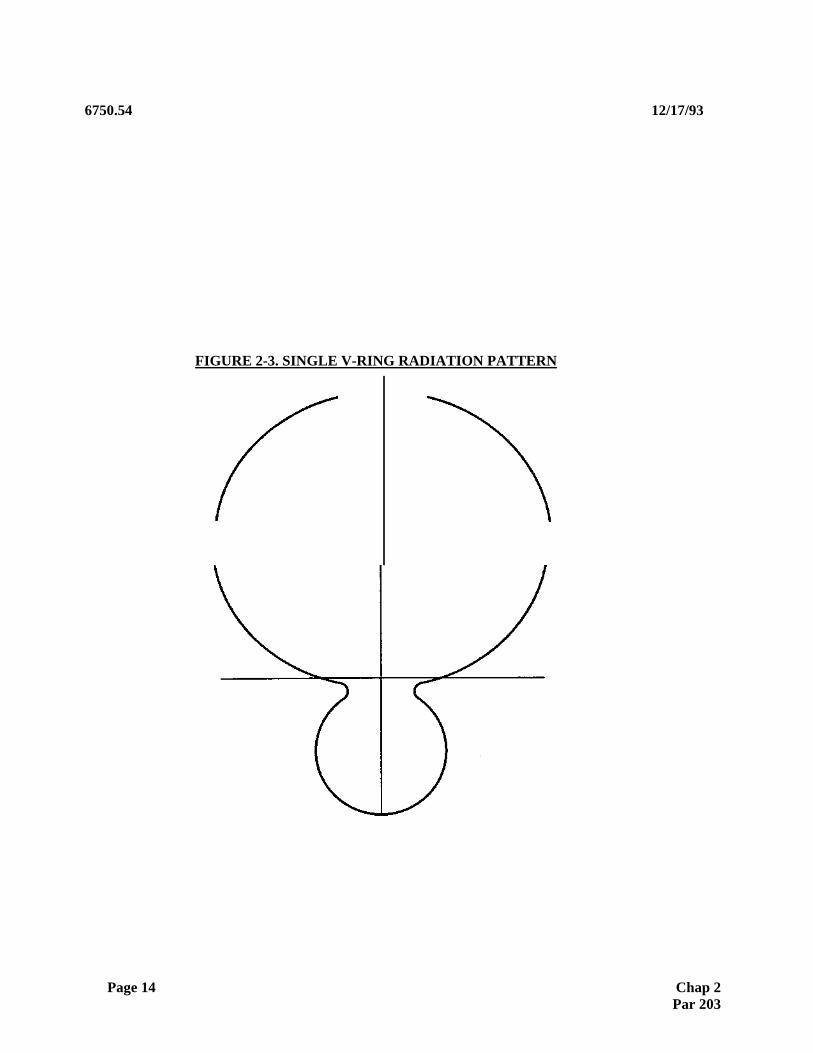
(2) Individual Antenna Characteristics. The V-Ring antenna consists of a loop or "ring" with a V shaped reflector attached to the rear of the antenna. Radio energy is fed to the ring through a coupler in the front of the ring. This coupler also provides a signal sample for integral monitoring purposes. The feed and monitor cables, as well as a heater are contained inside the ring. See figure 2-2 for a pictorial representation of a V-Ring antenna, and figure 2-3 for the radiation pattern of a single antenna.
(3) Front to Back Gain. The "V" shaped reflector portion of the antenna provides some gain in the forward direction. The front to back signal ratio for a V-Ring array is approximately 7 dB.
(4) Parasitics. The 15-element V-Ring array suffers from high parasitic mutual coupling, which can result in both radiated and monitored signal instability. The problems with parasitics are largely due to impedance mismatches within the system, and the center antenna which is fed a large portion of the total carrier power. The 8- and 14-element arrays do not have the center antenna, and the parasitic in these arrays do not pose a significant problem.
(5) Array Types.
(a) 15-Element. The 15-element V-Ring array is composed of seven pairs of antennas symmetrically spaced about the array centerline, and a center or "OC" antenna. This configuration is being phased out.
(b) 14-Element. The 14-element V-ring array is composed of seven antenna pairs, symmetrically spaced about the array centerline. The antennas of a pair are fed carrier energy in phase (SIP) and sideband energy out of phase (SOP). No horizontal front course radiation pattern for this array is shown here, but the pattern is similar to the 14-element log periodic dipole array, shown in figures 2-13 and 2-15. This array uses the same amplitude and phase distribution as the 14-element log periodic dipole array. This array is used for sites which require a back course, and that have a more challenging multipath environment. The 14-element and 15-element V-Ring are wide aperture, narrow beamwidth arrays.
(c) 8-Element. The 8-element V-Ring array is composed of four antenna pairs, symmetrically spaced about array centerline. The antennas of a pair are fed carrier energy in phase (SIP) and sideband energy out of phase (SOP). Figure 2-6 provides the antenna spacing and the array amplitude and phase distribution, and a graphical representation of the 8-element V-Ring array. Figure 2-7 provides a representative horizontal radiation pattern for this array. This array has an amplitude and phase distribution which is identical to the 8-element log periodic dipole array. In fact, the RF distribution unit provided for the log periodic array is used for the 8-element V-ring. This array is used for sites without significant multipath (reflection) problems, where there is a need for a backcourse approach capability. The 8-element array is a narrow aperture, wide beam width array.
Page 12 Chap 2 Par 203

12/17/93 6750.54
FIGURE 2-2. V-RING ANTENNA
Chap 2 Par 203 Page 13
6750.54 12/17/93
FIGURE 2-3. SINGLE V-RING RADIATION PATTERN
Page 14 Chap 2 Par 203

12/17/93 6750.54
FIGURE 2-4. 15-ELEMENT V-RING COMPOSITE RADIATION PATTERN FRONT COURSE
FIGURE 2-4 V-RING ARRAY COMPOSITE RADIATION PATTERN
Chap 2 Par 203 Page 15
V-RING ANTENNA ARRAY

6750.54 12/17/93
FIGURE 2-5. 15-ELEMENT V-RING ARRAY
SPACING PROM CENTER
PAIR NUMBER BAND A BAND B
L1
56.360 INCHES 55.700 INCHES L2 148.870 INCHES 147.100 INCHES L3 237.340 INCHES 234.520 INCHES L4 337.880 INCHES 333.920 INCHES L5 434.440 INCHES 429.320 INCHES L6 531.00 INCHES 524.720 INCHES L7
627.560 INCHES 620.120 INCHES
BAND A - 108.1 TO 109.3 MHz
BAND B - 109.5 TO 110.5 MHz BAND C - 110.7 TO 111.9 MHz
ARRAY
DIRECTION OF RADIATION
Page 16 Chap 2 Par 203
NOTE: 'E' NUMBERS TO BE MARKED BY INSTALLATION CREW ON V-RING MAST APPROX. 4' UP MAST ON DISTRIBUTION UNIT SIDE OF ARRAY AND ON TOP OP V-RING ANTENNAS. USE 1' HIGH LETTER STENCIL MITH BLACK STENCIL INK. MARKINGS ARE FOR IDENTIFICATION AND RELOCATION, SHOULD MORE THAN ONE ANTENNA BE REMOVED AT A GIVEN TIME.
BAND C
55.050 INCHES 145.410 INCHES 231.820 INCHES 330.020 INCHES 424.330 INCHES 518.640 INCHES 612.950 INCHES

12/17/93 6750.54
FIGURE 2-6. 8-ELEMENT V-RING SPACING, AMPLITUDE, AND PHASE DISTRIBUTION
1 1R 2R 3R 4R
.1' 1 7 1 7 I ' 3 2 3 1
p 2 z
i I I ~ f ~
19 3 2 6 1 1 2 1 9 3 2 - I
277 6 ___ 4- ______ 273 8 - ~
CSB DISTRIBUTION B-E:.EMENT 4L 3L 2L 1L 1R 2R 3R 4R
AMP 0.059 0.142 0.362 1.001 1.001 0.36: 0.162 0.05°_
PHASE 180° 0° 0° 0° 0° 0° 0° 180°
SBO DISTRIBUTION
AMP 0.701 0.891 1.001 1.001 0.891 0.701 0.415 PHASE 0° 0° 0° 0° 180° 180° 180°
180°
Chap 2 Par 203 Page 17

6750.54 12/17/93
FIGURE 2-7. 8-ELEMENT V-RING (ONE-FREQUENCY) LOCALIZER ANTENNA ARRAY
LOCALIZER ANTENNA ARRAY RADIATION PATTERN PLOT
Antenna type: V-ring
Number of antennas: 8
Course width: 5
Notes: C=CSB, S=SBO, D=DDM, and *=Line intersection.
DDM=0.4*SBO/CSB
Page 18 Chap 2 Par 203
Antennas amplitude and degrees spacing:
CSB SBO Degrees
Pair 1 1.000 1.000 108 Pair 2 0.360 0.890 378
Pair 3 0.140 0.700 648 Pair 4 -.055 0.420 918
RELATIVE AMPLITUDE, LINEAR SCALE 0 0.9 0.8 0.7 0.6 0.5 0.4 0.3 0.2 0.1 0.0
0.5 0.4 0.3 0.2 0.1 0.0 DDM
DEG CSB SBO 35.0 0.23 0.2134.0 0.23 0.2233.0 0.23 0.2432.0 0.23 0.2431.0 0.23 0.2530.0 0.22 0.2529.0 0.22 0.2428.0 0.21 0.2427.0 0.21 0.2326.0 0.21 0.2125.0 0.21 0.2024.0 0.21 0.1923.0 0.22 0.1822.0 0.24 0.1821.0 0.26 0.1920.0 0.28 0.2019.0 0.32 0.2318.0 0.35 0.2717.0 0.40 0.3316.0 0.44 0.3915.0 0.49 0.4614.0 0.54 0.5313.0 0.60 0.6012.0 0.65 0.6711.0 0.70 0.7310.0 0.75 0.789.0 0.79 0.808.0 0.84 0.817.0 0.87 0.796.0 0.91 0.745.0 0.94 0.674.0 0.96 0.573.0 0.98 0.452.0 0.99 0.311.0 1.00 0.160.0 1.00 0.00

12/17/93 6750.54
FIGURE 2-8. TRAVELING WAVE ANTENNA VERTICAL RADIATION PATTERN
210° 150° 200° 160°190° 170°
1800 170° 190° 160° 200°
150° 210°
14C° 220°
130° 230°
120° 240°
110° 250°
100° 260°

12/17/93 6750.54330° 30° 340° 20° 350° 10°
00 10° 350° 20° 340° 30° 330°
Chap 2 Par 203 Page 19

b. Los Periodic Dipole (LPD) Antenna Systems.
(1) Background. The log periodic dipole antenna system was procured with the Mark I D localizer equipment manufactured by Wilcox Electric. Other manufacturers make log periodic antennas, but the Wilcox type is the most common within the FAA, and the others have similar signal in space characteristics. The log periodic is the only localizer antenna which is currently being procured by the FAA, and is used for facilities in all categories of operation. The LPD antenna does not provide a back course capability.
(2) Individual Antenna Characteristics. The log periodic dipole localizer antenna is a broadband antenna which consists of seven parallel, horizontally polarized dipole radiators fed from a common balanced transmission line inside the antenna. The transmission line is excited from the front and produces a traveling wave that progresses towards the rear of the antenna. The excitation of a particular dipole is dependent upon the electrical length at the operating frequency. Broadband characteristics are obtained by varying the dipole lengths and spacings such that the resonant element moves from one dipole to the next as the operating frequency changes. A pictorial representation of the antenna is provided in figure 2-10, and the antenna element radiation pattern is shown in figure 2-11. The half power beamwidth is approximately 46 degrees, and almost no energy is radiated at right angles to the antenna is. The LPD antennas do provide for integral monitoring. Each antenna is mounted approximately 6 feet above the ground on two frangible supports. The antenna is approximately 9 feet long and 50 inches wide.
(3) Front to Back Gain. The LPD antenna provides a front to back ratio of nearly 23 dB, and radiates no significant energy in the back course sector.
(4) Parasitic. The log periodic dipole antenna arrays suffer from no significant parasitic, since the radiation at right angles to the antenna axis is approximately 30 dB down.
(5) Array Types.
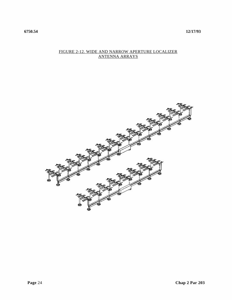
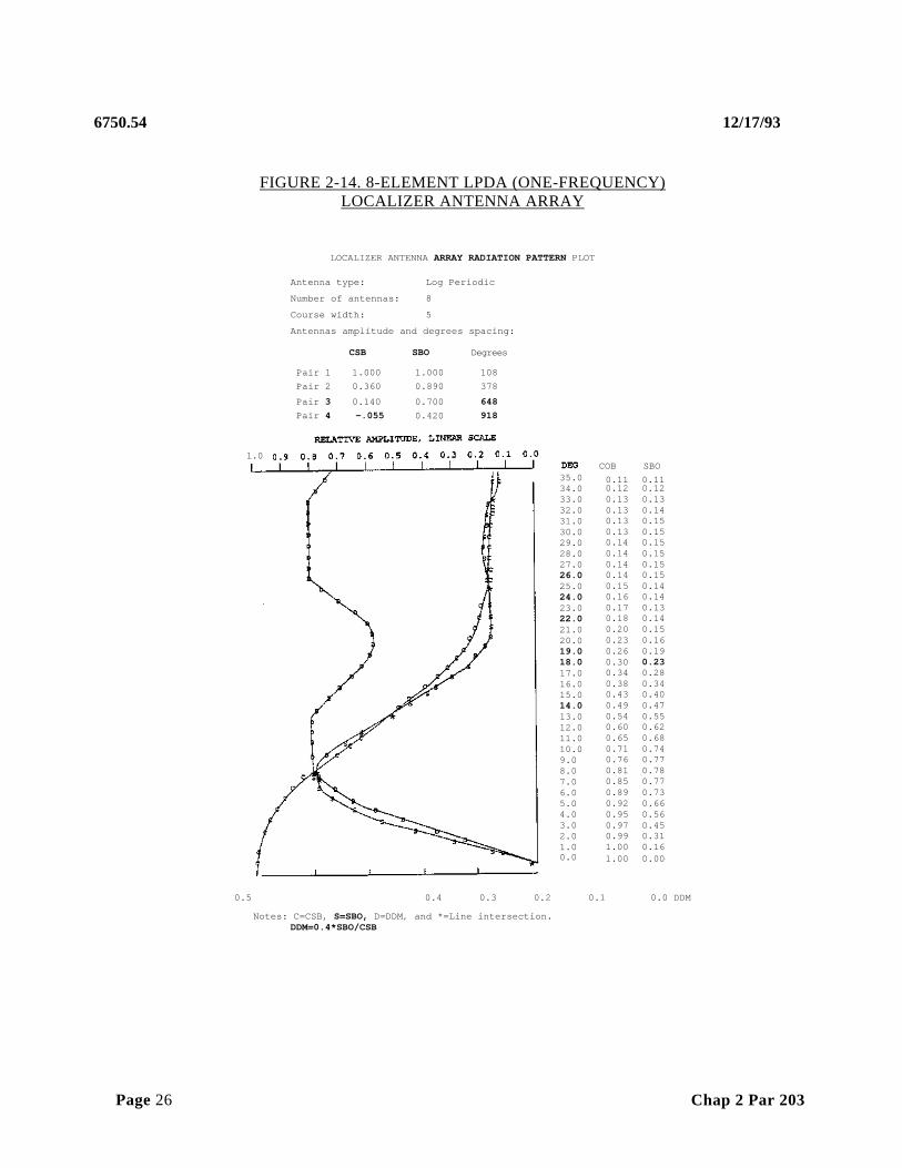
(a) 8-Element. The 8-element log periodic dipole array is composed of four antenna pairs, symmetrically spaced about the array centerline. The antennas of a pair are fed carrier energy in phase and sideband energy out of phase. Figure 2-12 shows a pictorial representation of the array. Figure 2-13 shows the array spacing, as well as the horizontal radiation pattern for this array. An expanded horizontal pattern is provided in figure 2-14. Figure 2-13 provides the amplitude and phase distributions for the carrier and sideband signals. The 8-element array is a narrow aperture, wide beamwidth array.
Page 20 Chap 2 Par 203

6750.54 12/17/93
FIGURE 2-9. TYPICAL GROUND-MOUNTED TRAVELING WAVE ARRAY-TYPE I
V
of
r , A!!1/! 4 ` 1T !#'~'!! A. s s m a r m . aL a a ®
s , k ; ~ r b : ` A ' ' C,~ :C,x `, :~ ;. :~ ' k : ' ~ } - ' r ' ' ~ z • : y x ' y ` z • ' y k
Y ` r r Y ~ i r Y ~ i r Y ~ l r Y ~ i , Y ~ i / Y ~ i r Y ~ / I • Y ~ ; ~ i, ; ; ' a 4 r Y ~ i r Y ~ i . Y ~ / i r Y ~ i r L a i r Y ~ i r Y ~ / I r Y ~ i r Y ~ i r Y ~ i r Y ~ i r Y ~ i r Y ~ Y ~ i r Y ~ i , Y ~ / r r Y ~ i r Y ~ j r Y ~ r r Y
( i N / r ' Y ~ Y
y z ' va tia' ;4;e, N~/ir Y~r Nr Y~irY4 Y~ir Y~r Y~rr Y~r Y~~, Y~r Y~r, Y;r Y~r Y~irYJrr Y ir Y~r Y~rr Y i Y~ir Y ir Y~r, dir Y`r .ji i ' , ' : / k J V
Chap 2 Par 203 Page 21

12/17/93 > % . r . l . _ _ _ _ _ _ _ _ _ _ _ _ _ _ _ _ _ _ _ _ _ _ _ _ _ _ _ _ _ _ _ _ _ _ _ _ _ _ _ _ _ _ _ _ _ _ _ _ _ _ _ _ _ _ _ _ _ _ _ _ _ _ _ _ _ _ _ _ _ _ _ _ _ _ _ _ _ _ _ _ _ _ _ ' , ' : / _ _ _ _ 6750.54
FIGURE 2-10. LPD ANTENNA

6750.54 12/17/93
Page 22 Chap 2 Par 203

12/17/93 6750.54
FIGURE 2-11. LOG PERIODIC DIPOLE ANTENNA HORIZONTAL RADIATION PATTERN
Chap 2 Par 203 Page 23
0°
6750.54 12/17/93
FIGURE 2-12. WIDE AND NARROW APERTURE LOCALIZER ANTENNA ARRAYS
Page 24 Chap 2 Par 203

12/17/93 6750.54
FIGURE 2-13. 8- & 14-ELEMENT LPDA RADIATION PATTERNS, ANTENNA SPACING, PHASE AND AMPLITUDE
TO RUNWAY
4 7L 6L SL 4L 3L 2L 1L 1R 2R 3R 4R SR
,II , I , I I I 1 7 I ' ~ 7 I I I I ~ I
32 3 ~ 132 32 I I I I I I I I I.---193 32 16 112193 2 - ~ I I I 273 8 _____ 273 8 - I
354 32 ______________________ 354 32 i
P ______________ 434 16 _____________ 'I ________ 434 16 1
51532 _________________ ~~~ ___________________ 51532 _________________ A
CSB DISTRIBUTION 8-ELEMENT
4L 30. 2L IL 1R 2R 3R 4R
AMP 0.051 0.143 0.363 1.001 1.001 0.363 0.143 0.05_
PHASE 180° 0° 0° 0° 0° 0° 0° 100° SBO DISTRIBUTION
AMP 0.41E 0.701 0.89C 1.00C 1.001 0.89C 0.70C 0.41_
PHASE O° 0° 0° 0° 180° 180° 180° 180° CSB DISTRIBUTION 14_PL
71. 6L 51. 4L 31. 2L IL 1R 2R 3R 4R 5R 6R 7R
AMP 0.06C 0.06C 0.2122 0.212 0.394 0.394 1.OOC 1.00C 0.394 0.394 0.212 0.212 0.06C 0.06C
PHASE _ 0° 0° 0° 0° 0° 0° 0° 0° 0° 0° 0° 0° 0° 0° _
SBO DISTRIBUfIONAMP 0.135 0.375 0.276 0.58E 0.414 0.755 1.00C 1.001 0.755 0.414 0.58€ 0.27E 0.375 0.13E
PHASE 0° _ 0° 0° 0° 0° 0° 0° 180° 180° 180° 180° 180° 180° 180° 8-E[.ffi~NT 14-ELEMENT
1.0 1.0 l 0.9 0.9
0.8 0.8
0.7 0.7
1 0.6
0 c 0 60.5 F
a 1 0.5 0.
1 0 4 1 0.4 1
0.3 0.3 1
0.2 0.2 0.1
0.1
00 10° 20° 30° 40° 50° 60° 70° 80° 90° 0
DEGREES
Chap 2 Par 203 Page 25
6RI 7R
NOTE: PHANTOM ANTENNAS USED ON WIDE APERTURE SYSTEM ONLY
1 1 1 1 1 I
1 1
SBO PATTERN
LEGEND
CSB PATTERN
6750.54 12/17/93
FIGURE 2-14. 8-ELEMENT LPDA (ONE-FREQUENCY) LOCALIZER ANTENNA ARRAY
LOCALIZER ANTENNA ARRAY RADIATION PATTERN PLOT
Antenna type: Log Periodic
Number of antennas: 8
Course width: 5
Antennas amplitude and degrees spacing:
CSB SBO Degrees
Pair 1 1.000 1.000 108 Pair 2 0.360 0.890 378
Pair 3 0.140 0.700 648 Pair 4 -.055 0.420 918
0.5 0.4 0.3 0.2 0.1 0.0 DDM
Notes: C=CSB, S=SBO, D=DDM, and *=Line intersection. DDM=0.4*SBO/CSB
Page 26 Chap 2 Par 203
COB SBO 0.11 0.110.12 0.120.13 0.130.13 0.140.13 0.150.13 0.150.14 0.150.14 0.150.14 0.150.14 0.150.15 0.140.16 0.140.17 0.130.18 0.140.20 0.150.23 0.160.26 0.190.30 0.230.34 0.280.38 0.340.43 0.400.49 0.470.54 0.550.60 0.620.65 0.680.71 0.740.76 0.770.81 0.780.85 0.770.89 0.730.92 0.660.95 0.560.97 0.450.99 0.311.00 0.161.00 0.00
1.0
35.0 34.0 33.0 32.0 31.0 30.0 29.0 28.0 27.0 26.0 25.0 24.0 23.0 22.0 21.0 20.0 19.0 18.0 17.0 16.0 15.0 14.0 13.0 12.0 11.0 10.0 9.0 8.0 7.0 6.0 5.0 4.0 3.0 2.0 1.0 0.0


12/17/93 6750.54
FIGURE 2-15. 14-ELEMENT LPDA (ONE-FREQUENCY) LOCALIZER ANTENNA ARRAY
LOCALIZER ANTENNA ARRAY RADIATION PATTERN PLOT
Antenna type: Log Periodic
Number of antennas: 14 Course width: 5
Antennas amplitude and degrees spacing:
CSB SBO Degrees Pair 1 1.000 1.000 108 Pair 2 0.394 0.759 378 Pair 3 0.394 0.414 648 Pair 4 0.212 0.586 918 Pair 5 0.212 0.276 1187
Pair 6 0.060 0.379 1457
Pair 7 0.060 0.138 1727
Notes: C=CSB, S=SBO, D=DDM, and .=Line intersect ion. DDM=0.4•SBO/CSB
DEG CSB SBO 35.0 0.09 0.07 34.0 0.09 0.08 33.0 0.09 0.09 32.0 0.09 0.10 31.0 0.09 0.11 30.0 0.09 0.11 29.0 0.09 0.11 28.0 0.10 0.11 27.0 0.10 0.11 26.0 0.11 0.10 25.0 0.12 0.10 24.0 0.13 0.10 23.0 0.13 0.10 22.0 0.14 0.11 21.0 0.15 0.12 20.0 0.15 0.14 19.0 0.16 0.16 18.0 0.17 0.17 17.0 0.18 0.17 16.0 0.19 0.17 15.0 0.19 0.16 14.0 0.20 0.15 13.0 0.20 0.14 12.0 0.21 0.15 11.0 0.21 0.17 10.0 0.23 0.20 9.0 0.27 0.26 8.0 0.32 0.32 7.0 0.40 0.39 6.0 0.49 0.44 5.0 0.60 0.46 4.0 0.72 0.44 3.0 0.83 0.39 2.0 0.92 0.29 1.0 0.98 0.15 0.0 1.00 0.00
0.5 0.4 0.1 0.0

12/17/93 6750.54
Chap 3 Page 81
Chap 2 Par 203 Page 27
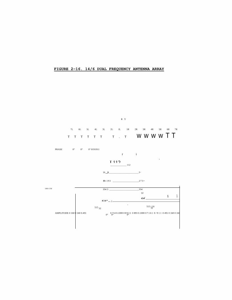
FIGURE 2-16. 14/6 DUAL FREQUENCY ANTENNA ARRAY
R Y
7L 6L 5L 4L 3L 2L IL 1R 2R 3R 4R 5R 6R 7R
T T T T T T T . T w w w w T T
PRASE 0° 0° 0° 0191911
r i ,
______________ 112
16_____16_________________________ I~
193 - 1 9 3 _______________________2 7 3 +
354 3 __________________________354 32
1 1 434i ______________________________
4 3 4 * __ : ___________________________________________________________ .
515 i 16 515 32 32
AMPLITODE 0 160 0 160 0.491 0 714 0.1000 0 8 9 3 1 0 893 0.1000 0 7 1 6 1 0 / 9 1 1 0 491 0 160 0 160 0° 0° 0°
L112
ORS C5B

Page 28 Chap 2 Par 203
• MPU=E 0.367
• PNASB 0°
• t M P U = 8 • exASe
• I M P U = Z • PlUSE
1.000 0.667) 0.222) 0.222
0° 0° 0° 180°
0.200) 0.000) 1.000 1.000 0° 0°I 0°I 0°
0.139 0.333) 1.0001 1.000
0°) 0°I 0°1 180°
0.555
0°
0.889
0°
1.000
0°0.555180°
0.367 1.000180°
0.889180°
0.000
0.333
180°
0.667180°
1.000 180°

6750.54 12/17/93
12/17/93 6750.54
CSB PATTERN
8 0 °4 0 ° 60° 20 180° 1 0 0 ° 170° 14o° 160°
Chap 2Par 203 Page 29
FIGURE 2-17. 14/6 DUAL FREQUENCY COURSERADIATION PATTERN (CSB + SBO)
l T
-0. 9
-o. 4
LEGEND
SBO PATTERN
1 1 1 111
- 0 .
- 0 .
0 .
0 .
o.
0
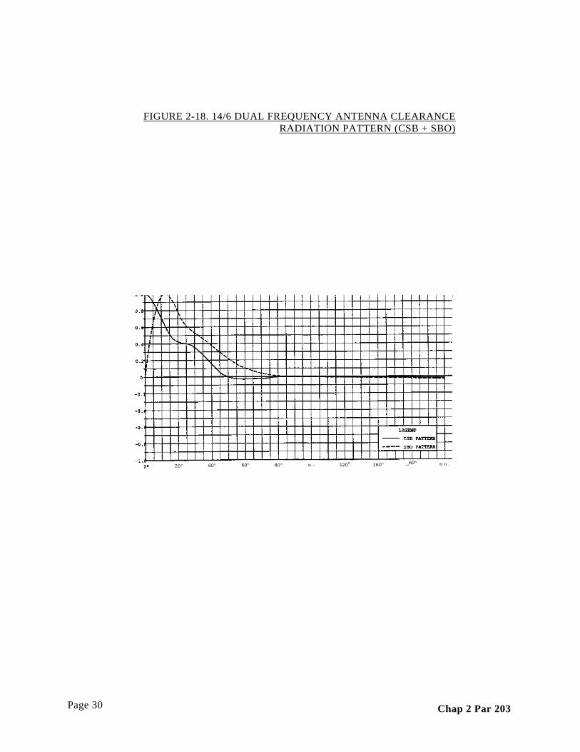
FIGURE 2-18. 14/6 DUAL FREQUENCY ANTENNA CLEARANCE RADIATION PATTERN (CSB + SBO)
Page 30 Chap 2 Par 203
20° n o . _60^ 160° 1208o -80° 60°60°

6750.54 12/17/93
(b) 14-Element. The 14-element LPD array is composed of seven antenna pairs, symmetrically spaced about the array centerline. The antennas of a pair are fed carrier energy in phase (SIP) and sideband energy out of phase (SOP). Figures 2-13 and 2-15 provide the horizontal radiation pattern for this array. Figure 2-13 provides the amplitude and phase distribution for carrier and sideband signals, as well as the location of each antenna with respect to array centerline. This array is used at sites that have a more challenging multipath environment. The 14-element log periodic dipole array is a wide aperture, narrow beamwidth antenna array. No significant radiation is present outside of plus and minus 35 degrees from the array centerline.
(c) 14/6 Dual Frequency. The 14/6 dual frequency array has antenna spacing which is identical to the 14-element LPD array. This array utilizes the AM "capture-effect" phenomena to reduce the effects of reflections from structures outside the active localizer course. The "clearance" signals are phase locked to the course signals, and there is a fixed frequency difference of approximately 9 kHz between course and clearance signals. The course signal is fed to all 14-elements, while the clearance signal is fed to the inner 6-elements (3 pairs). The course signal is approximately 10 dB stronger than the clearance signal on path, while in the clearance sector, the clearance signal predominates by 10 dB (approx.). This ensures that the aircraft receiver is "captured" on the course signal while on course, and clearance signals reflected onto the localizer course have little or no effect. For a more detailed discussion of capture-effect principles, see chapter 2 of Order 6750.49, Maintenance of ILS Facilities, or the equipment instruction book. Figure 2-16 provides the amplitude and phase distribution for this array. Figures 2-17 and 2-18 provide the horizontal radiation patterns for the course and clearance signals, respectively. This array is provided at some Category IUIII facilities. For Category I facilities, this array is installed when there is an extremely challenging multipath environment. The 14/6 dual frequency array is a wide aperture, narrow beamwidth antenna array.
(d) Others. At the time of the publication of this order, there are two other types of log periodic dipole antenna arrays which are in use at a few sites or are under development. These arrays are wider aperture than the 14-element array, and are dual frequency "capture-effect" arrays. These arrays are for use at extremely challenging sites where a 14/6 dual frequency array does not provide satisfactory performance. No data on these arrays is included in this order. For details on these arrays, consult the applicable manufacturer's instruction book.
204. INTEGRAL MONITORING. All current FAA localizer antenna systems use integral monitoring techniques. A signal is sampled from each individual antenna and is fed to the RF combining unit. The RF combining unit combines these signals and provides carrier and sideband outputs, which are then fed to a monitor combining network. The monitor combining network combines the carrier and sideband signals to provide outputs which represent the far field conditions, typically one at the on-course position, and one at the edge of course position. These RF outputs are then detected, and the detected audio is fed to the proper monitor channel. With the exception of the Mark IB equipment, the detection occurs in the distribution unit housing (at the antenna system), and the audio is fed from the antenna system to the shelter over audio cables. The Mark IB equipment feeds the RF signal back to the equipment shelter, and it is detected inside the monitor. The detectors used for all systems are linear envelope detectors, and the design varies with each type of equipment. While integral monitoring techniques will accurately detect changes in the signal due to electronics or antennas, it
Chap 2 Par 203 Page 31

12/17/93 6750.54
will not account for signal errors due to physical changes in the array, multipath and other anomalies. A number of techniques have been implemented to augment the integral monitoring. Misalignment detectors are installed on localizer arrays that have a single pedestal supporting an element of the antenna array and usually consist of a cable strung through brackets on each antenna, connected to a switch assembly in the middle of the array. If an antenna falls over or changes position, the movement of the cable causes a misalignment alarm, shutting down the localizer. Cable fault monitoring is accomplished by placing a DC voltage on the center conductors of the coaxial cables. Far-field monitors are used on Category II/III systems to provide additional integrity monitoring. Due to the nature of these far-field monitors, a time delay is usually placed on the alarm, so that momentary aberrations caused by taxiing or landing aircraft do not cause an equipment shutdown. See the appropriate manufacturer's instruction book for detailed information on the operations of these monitors.
205.-208. RESERVED.
Page 32 Chap 2 Par 204

SECTION 2. ELECTRONIC INSTALLATION
209. PURPOSE. The purpose of this section is to provide guidance which is not specific to one type of localizer, but can be generalized to any type of localizer in use by the FAA. This information will supplement the installation and tuneup procedures contained in the equipment instruction books. The guidance in this section must be combined with the procedures in the instruction books, as well as regional guidance or standards that may be in place. The procedures in this section are not meant to be step by step, instruction book type procedures. For array specific details, consult the appropriate instruction book. The procedures herein assume that the reader is proficient in use of RF test equipment (vector voltmeter, signal generator, etc). For guidance in siting the localizer antenna array and equipment shelter, consult the latest version of Order 6750.16.
210. GENERAL. a Physical
Construction Details.
(1) General. Physical construction details should be contained in the standard drawings for each type of system and in Order 6750.36, Site Survey, Selection, and Engineering Documentation for ILS and Ancillary Aids. Construction engineering personnel in the regions should be experienced in this area and should be consulted for appropriate regional drawings. Also included is some information which is not contained in the equipment instruction books. Prior to physically installing any RF hardware (including antennas, distribution/recombing networks), the checkout procedures contained in this section shall be accomplished on each piece of equipment.
(2) Construction of Localizer Supports. The localizer antennas may be installed on separate concrete piers, or a concrete pad may be used to support the entire array. Electronic installation personnel should pay particular attention to the placement of the antenna supports, since the supports can affect the physical alignment of the antenna way. Rebar in the concrete pad should be installed such that o n areas are left where the antennas supports are to be bolted down to the concrete. This will allow drilling for the anchor bolts for each antenna to be accomplished without hitting any rebar. Several brass survey disks are usually placed in the concrete pad (or new the piers) to assist with the physical alignment of the way with respect to the desired approach path (centerline). These disks can be marked by a surveyor for extended runway centerline, etc. Disks are usually set in concrete both in front of and behind the array to mark runway centerline, and along the is of the way to mark a line perpendicular to centerline. The line perpendicular to centerline should be marked for both antenna supports in the case of a log periodic dipole array. Even when the concrete pad (or piers) for the array is pre-existing (e.g., when performing a 15-element to 8/14-element V-Ring conversion), a new survey of extended centerline and the lines perpendicular to centerline is highly recommended. It is not uncommon on a refurbish job to find that the existing array is a foot or more off from extended centerline, perhaps due to runway overlays, or misplacement of the original array. A qualified surveyor should be used for marking extended centerline. If possible, use the same surveyor which is used by the airport for surveying the runway. This surveyor will be familiar with the existing centerline markers.

12/17/93 6750.54
Chap 2 Par 209 Page 33

6750.54 12/17/93
Page
(3) Antenna Array Physical Alignment. Physical alignment of the array should be done carefully, since tuneup procedures for the localizer equipment assume proper alignment of the array with respect to the desired approach path. All antennas should be level, and a line drawn through the array should be perfectly perpendicular to centerline. Consult the manufacturer's instruction book for further guidance on physical alignment of the array, and for step-by-step procedures on how to put the antenna array together.
(4) Cables. All cables between the equipment shelter and the antenna array shall be either rated for direct earth burial or installed in an appropriately sized conduit. The most commonly used cable is RG-331/U. However other cables such as phase swept RG-214U or heliax cables may be used. Proper engineering practice dictates that due consideration be given to installing spares for the coaxial and signal cables. Proper coordination must be accomplished when installing cables so that other cables on the airport are not damaged. Consult the manufacturer's instruction book to determine the number and type of cables needed for a particular localizer equipment type. Care shall be taken to assure that the RF coaxial cables installed between the shelter and the array are the same physical length. Cables should be properly marked at each end for ease of identification.
b. Electronics Preparation. The following subparagraphs shall be accomplished prior to final array tuneup.
(1) Transmitter Equipment. The transmitter, monitor, and associated electronics shall be installed in accordance with the manufacturer's instruction book. The procedures provided in those manuals are considered adequate, and no additional guidance is required here. Tuneup of the transmitting equipment should be accomplished prior to beginning any tuneup on the antenna array. This includes termination of (audio) signal cables, and completion of the RF transmission path between the transmitter and the antenna array. There will be a need for short lengths of flexible cables at either end of the rigid low loss cables between the shelter and the array. These cables are required to connect the rigid cable from where it enters the transmitter building or antenna array, to the transmitter and RF distribution unit, respectively. When preparing these cables, leave sufficient extra cable to allow for proper phasing to be accomplished (leave at least one extra wavelength).
(2) RF Hardware/Antenna Checkout. Prior to beginning the physical installation of the antenna array, all RF hardware and the antennas shall be thoroughly checked out using a vector voltmeter. The antennas should be checked for voltage standing wave ratio (VSWR), and for the phase and amplitude of the monitor return signal. The other RF hardware should be checked for VSWR, amplitude and phase on all ports. Examples of RF hardware include the RF distribution and combining units, the monitor combining network. If any parameters checked are found to be outside of the tolerance specified in the equipment instruction book, that unit should be replaced. Consult each equipment instruction book for detailed procedures on checking the RF hardware and the antennas, and for the tolerances for each particular piece of equipment.
NOTE: When using a vector voltmeter, observe the cautions on maximum input levels. The input probes are easily damaged by high signal levels. The maximum signal level is usually 0 dBm.

12/17/93 6750.54
(3) RF Coaxial Antenna Cables. Since the proper operation of the localizer system depends in large part on the phase characteristics of the coaxial cables, care must be taken to properly prepare cables for installation and to prevent accidental damage. Time spent carefully verifying cable characteristics prior to use in the antenna array will result in a more stable system, and prevent problems in the long run. If the antenna feed and monitor lines are not supplied with the equipment (e.g., refurbish project), it will be necessary to prepare a set of cables. Whenever possible, all cables should be taken from the same reel so that the phase characteristics of the cables are uniform throughout the array. As a minimum, all feed cables should be from the same reel, all monitor cables from the same reel, etc. It is recommended that the cables be cut from the reel at the start of the installation, so that the cable has time to age during physical construction of the antenna array. The following procedures can also be applied to cables which are supplied by the equipment manufacturer. Cables from the manufacturer should have equal electrical lengths, and the installer should verify the lengths prior to installation in the antenna array. Take care not to step on the cables or otherwise damage them. Following are some steps which should be taken during cable preparation to ensure acceptable cable quality:
(a) Cut each cable from the reel to the proper physical length. All antenna monitor and feed cables should be the same physical length. Consult the equipment instruction book for the required length (which will vary with the width of the antenna array). Unroll the cable off the reel, and stretch the cables out flat. Make sure to designate an area for stretching out the cables where they can be protected from physical damage.
(b) If possible, the cables should be allowed to "age" outside prior to installation. Once cables are cut, alternately lay the cable out flat, then coil the cable each way. This will help to ensure that the dielectric characteristics are uniform throughout the length of each cable. Tape each end of t h e cables to prevent moisture damage.
(c) Run your hand along each cable and feel for any nicks, kinks, bulges in the cable, or other damage. A bulge in the cable may be caused during manufacture when the machine that weaves the braid (shielding) runs out of material, and a junction must be made. Replace any cables with bulges, kinks, etc. Prior to running the "end to end" cable check in the item below, a connector should be installed on one end of each antenna cable, and the cables cut to be the same electrical length. After installing a connector on each cable, measure the round trip electrical length of each cable using a vector voltmeter. Identify the shortest cable (most advanced phase), and cut all the cables to be within +/- 2 degree of that cable.
(d) An additional check of cable quality is to run an end to end comparison of electrical length. This requires that the coaxial connectors be installed on both ends of the cable. With a vector voltmeter, measure the round trip electrical length of each cable from both ends (alternately feed each end). If there is more than a few degrees difference in electrical length between the two ends, consider replacing that particular cable. Good cable should measure the same from end to end within a few degrees.
(4) Connectors. Connector construction can also have an effect on localizer system stability. The connectors should be put on very carefully. All connectors should be from the same
Chap 2 Par 210 Page 35

6750.54 12/17/93
Page
manufacturer. It is suggested that one person put connectors on all the feed and on all the monitor cables. This will ensure that each connector is done in the same manner. Refer to chapter 1, paragraph 8 for additional guidance on proper connector construction. If the antenna cables are supplied by the equipment manufacturer, the installer should sample the connectors for proper construction techniques. Remove several connectors and check that all connector parts are present and installed properly (e.g., washers on the right way). If any deficiencies are found, check all of the connectors on these cables.
(5) System Phasing. Prior to beginning antenna array tuneup, the system must be properly phased, and if the equipment provides for it, an in-line phasing detector installed. The following guidance is provided in those areas:
(a) CSB to SBO Phasing. The transmitter provides a phaser to allow for adjustment of the sideband only (SBO) to carrier (CSB) phasing. The cables between the transmitter and the antenna array should be trimmed so that when carrier and sideband signals are properly phased, the adjustment on the equipment phaser will be mid range (0 degrees). This procedure will be used to initially set up carrier to sideband phasing so that array optimization can begin. The procedure for confirming proper phasing is contained in Order 6750.49, Maintenance of ILS Facilities. The following steps provide a generalized procedure on accomplishing the initial CSB/SBO phasing:
NOTE: The SBO phaser on the transmitter may not be accurate throughout the full range of adjustment, and in this procedure it will only be used to initially determine how much extra line will be needed to optimize phasing. Extra line sections will be added until the phaser is centered. This is done to simplify cable cutting, since the extra line sections can easily be removed and measured with a vector voltmeter.
1 Complete the installation and checkout of all RF hardware at the array before proceeding.
2 At the antenna array, prepare and install jumper cables between the rigid cable at the antenna array and the RF distribution unit (one each is needed for CSB and SBO signals). These cables should be of equal length, and should provide enough extra cable to allow for later trimming.
3 Dummy load all antenna ports on the RF distribution unit except 3L.
4 On the RF distribution 3L port which is not loaded, install an RF body terminated with a dummy load. This may require fabrication of a short RF cable for use in physical connection of the in-line body. This cable should be of suitable length for use in the installation of the in-line phasing detector (see next section).
5 Turn off the transmitter, and dummy load the sideband output of the transmitter. Connect the CSB cable to its output port on the transmitter.
6 Turn on the transmitter, and connect a portable ILS receiver (PIR) to the RF body installed at the array. Verify that the reading is 0 DDM. Check modulation equality (modulation balance transmitter adjustment) if a non-zero DDM reading is present.

12/17/93 6750.54
7 Turn off the transmitter, and connect the SBO cable to its output port on the transmitter output.
transmitter. 8 Center the transmitter main SBO phaser (set to mid-range or zero). Turn on the
9 Observing the DDM reading on the PIR, adjust the main SBO phaser until zero DDM is read on the PIR. If zero DDM cannot be reached within the adjustment range of the main SBO phaser, add fixed line sections and adapters may be added in the sideband or carrier lines until zero DDM (quadrature phasing) can be reached by adjusting the main SBO phaser.
10 Install an elbow in the CSB line. (this has the effect of advancing the sidebands). Note the reading on the PIR. If the PIR reads predominantly 150 Hz, the sensing is reversed. Remove the elbow from the CSB line.
11 Note in which line the fixed sections were installed in step 10 (above), and whether or not reverse sensing was found in step 10 (above). Remove the fixed line sections and measure their electrical length with a vector voltmeter and note the reading. Add 180 degrees to this reading if reverse sensing was present. Cut the amount noted from the line in which the fixed line section was not installed (e.g., if fixed line sections were installed in the SBO line, cut the CSB line, and vice-versa).
(b) Phasing Detector. Some equipment provides for an in-line phasing detector, which allows monitoring of the carrier to sideband phasing from inside the equipment shelter. This is accomplished by installing an RF body and detector in one of the antenna lines (see instruction book for specific guidance). The detected audio is run to the equipment shelter using a spare audio pair. A jack can then be installed in the rack, or other appropriate place inside the shelter and used to conduct in-line phasing checks. Keep in mind that when the RF body is installed in one of the antenna lines, that line must be shortened by the length of the RF body and connecting cable in order to keep all antenna feedlines the same length. It is recommended that this detector be installed prior to final array tuneup. In line phasing can be used on all antenna arrays currently in use by the FAA. Consult the latest version of Order 6750.49 for guidance on use of the in-line phasing method.
(6) Preliminary Requirements. To assure that the optimization of the antenna array proceeds smoothly, the following shall be accomplished prior to beginning array optimization:
(a) The transmitter should be properly tuned for 20.0 percent modulation of the 90 and 150 Hz tones, and for modulation equality. Consult the equipment instruction book and/or Order 6750.49 for detailed procedures.
(b) Ensure that the PIR is calibrated and is in good working condition.

6750.54 12/17/93
Page
Chap 2 Par 210 Page 37

12/17/93 6750.54
(c) Using a vector voltmeter, verify the condition of all dummy loads, phasers and attenuators that will be used during tuneup procedures. Discard any dummy loads which do not pass VSWR checks (minimum return loss of approximately 25 dB should be measured).
(d) Establish ground checkpoints in accordance with Order 6750.49
211. TUNE UP PROCEDURES.
a. General Instructions. After the physical installation of the equipment has been accomplished, antenna system optimization can begin. Antenna system optimization will consist of measuring the amplitude and phase distribution to the antenna elements, and trimming cables and making other adjustments to obtain satisfactory signal in space performance. After antenna array optimization is complete, then the monitor can be optimized, and preparations for flight inspection completed.
NOTE: Do not start optimization until all procedures in paragraph 20 are completed.
b. General Procedures for Measuring Antenna Array Nulls. Optimization of most localizer antenna arrays requires that the null in the sideband signal from each antenna pair be measured, and the antenna feed lines cut to make the null coincident with the desired localizer course (most often the runway centerline). There are three methods for measuring antenna nulls which are commonly used. Some personnel may prefer one over another, but the important thing is to choose the method which you are most comfortable with, and that gives repeatable, predictable results for your installation job.
(1) All antenna null measurements should be made at a suggested distance of 1000', and an absolute minimum distance of 450'. All of the nulls should be measured at the same distance away from the array. The stop end of the runway is usually a convenient point, since the distance to the array is usually 1000'. Greater distances are permissible but null measurements are subject to multipath effects due to reflections from buildings, etc., which will be worse further away from the array. If results of a null check are questionable and you suspect multipath problems, some investigation may be warranted. Since multipath effects are a function of distance from the array, make a few null checks at varying distances from the array. The angular displacement of the null from centerline should be independent of the distance from the array (inches away from centerline divided by the distance from the array should be a constant value). If significant differences are found, a new location may need to be established to conduct null checks. Effects of multipath can be minimized by using a directional antenna, such as a yagi which is made for localizer frequencies.
(2) When measuring nulls, one person should be out at the measurement point with the PIR. Additional people should stand directly behind the person with the PIR to prevent effects on the null readings. Keep the PIR level, with the antenna oriented properly (parallel) with respect to the array. Personnel working at the array should be well behind the center of the array when null measurements are made. Note that nulls for inside antenna pairs (shortest spacing between antennas) will be very broad, while the nulls for outside pairs will be more narrow.

(3) When measuring a DDM or RF null, move the PIR back and forth, pausing incrementally to note RF or DDM dips which indicate a null. The transmitter should be adjusted so that the RF signal received by the PIR is at a low level, where minimum Automatic-Gain Control (AGC) action occurs. If the signal strength is too high to easily define a null, reduce the transmitter power in steps until nulls are more easily defined.
(4) DDM Method.
be radiating. (a) Configure the facility normally, with the exception that only one antenna pair should
(b) Dummy load all unused antennas, cables, ports.
(c) Proceed to the point chosen for null measurements. Walk across the localizer course with the PIR and look for the 0 DDM point. The point where zero DDM occurs will be coincident with the sideband RF null for that antenna pair. Record this value.
(d) Repeat this procedure as required for each antenna pair, and for the entire array (composite sideband null) with all antennas energized.
NOTE: This method requires that the transmitter be tuned properly, the CSB/SBO phasing is optimum, and that the PIR be properly calibrated.
(5) RF Bracket Method.
(a) Configure the facility to radiate carrier into the sideband port of the distribution unit, with only one antenna pair radiating at a time. The SBO transmitter output should be dummy loaded.
(b) Dummy load all unused ports, antennas, and cables.
(c) Proceed to the point chosen for the antenna null measurements. Walk across the localizer course (keeping a constant distance from the antenna array), and try to identify roughly where the null occurs by looking for the minimum signal indication on the RF level meter of the PIR. Note the level on the RF meter and mark this point on the ground temporarily (for reference only).
(d) Walk to one side of the null until you achieve an RF level suitable for use as a reference level (make sure that a reasonable change from the minimum RF level occurs). Note the RF level reading and mark this point on the ground.
NOTE: The null position found in subparagraph 21b(5)(f) should be reasonably close to that marked in subparagraph 21b(5)(c). If not, repeat the check.
Chap 2 Par 211 Page 39

12/17/93 6750.54
(e) Walk to the other side of the null until the RF level again reads the reference level. Mark this point on the ground.
(f) The null position will be halfway between the two points where the reference RF level reading was found. Use a tape measure to mark the halfway point, and then determine the null offset from centerline. Record this value.
(g) Repeat this procedure as required for each antenna pair, and for the entire array (composite sideband null), with all antennas energized. The RF bracket method is particularly useful for the inside pairs, where the null is very broad and it is hard to accurately determine the minimum value on the RF meter.
(6) RF Null Method.
(a) Configure the facility to radiate CSB into the SBO port with one antenna pair connected. Tum off the 90 and 150 Hz modulation, and turn the 1,020 Hz indent tone to constant. Dummy load all unused ports, antennas, cables, etc.
(b) Proceed to the point selected for measurement of null position and connect a headset to the PIR.
(c) Walk across the localizer course at the selected distance, and use a headset (plugged into the PIR) to listen for the minimum of the 1,020 audio tone. The minimum audio tone will correspond to the position of the sideband null. Record the position of the null with respect to the desired approach course.
(d) Repeat this procedure as required for each antenna pair, and for the entire array (composite sideband null), with all antennas energized.
(e) For further discussion of the RF null method, see the measurement procedure for composite sideband null in the latest edition of Order 6750.49.
c. General Procedure For Antenna Array Optimization. This procedure is intended for use with any of the antenna arrays/types, with the exception of the 15 element V-Ring which is being phased out. Consult subparagraphs 21d and 21e for antenna and array specific guidance.
NOTE: All of these procedures require trimming of the antenna feed cables. When trimming cables, use extreme caution to avoid overcutting. Doublecheck calculations before the cut, being conservative in rounding off fractions. Measure the cable trim length with a scale graduated in tenths of inches.
(1) Pair to Pair Phasing of Antenna Tielines. One step that is left out of many optimization procedures is pair to pair phasing. Conduct this step just before you are ready to begin measuring and "cutting in" the antenna nulls. The goal of this procedure is to cut the tie lines on one side of the array to be the same length. Note that many pair to pair phasing procedures require measurement of the antenna feed cable length, but the signal path for the test equipment setups always include the RF
Page 40 Chap 2 Par 211

distribution unit. at you will actually measure is the RF transmission path length, which includes all RF paths between the input to the distribution unit and the antennas.
NOTE: For V-Ring Arrays, this procedure, which measures the RF transmission path length from the input of the distribution unit to the input of the antenna can be used. However, you can also measure the phase using the hang on antenna probe. Measuring with the antenna probe will take into account the differences (which should be small) in radiated phase caused by the differences between antenna couplers. The phase measured by the hang on probe may be affected by parasitics. Use the hang-on probe only when one antenna is radiating at a time.
(a) Disconnect and dummy load all antennas except the cable under test.
(b) Set up the test equipment as shown in figure 2-20. (See 21c(1)(f))
(c) Configure the facility to radiate carrier into the sideband port of the distribution unit.
(d) Dummy load the SBO output of the transmitter.
(e) At the antenna, disconnect the cable whose path length needs to be measured. Both need the set up of the test equipment as shown in figure 2-20.
(f) Measure and record the electrical RF transmission path length for the subject antenna using a vector voltmeter. Repeat above measurements until the path length for each antenna has been measured.
NOTE: The test equipment setup in figure 2-20 measures open tielines, so the indicated phase meter measurement on the vector voltmeter will be twice the actual length (round trip length).
(g) Identify the shortest cable (path length) in the array (shortest cable will have the most advanced phase).
(h) For each cable on the same side of the array as the shortest cable, calculate the length of cable which needs to be cut to match the length of the shortest cable. (At localizer frequencies for RG-214/U, one inch is roughly equal to five electrical degrees).
(i) Trim all of the cables on the same side of the array as the shortest cable as required, per the calculations made the previous step. Be sure not to cut too much cable (be conservative).
a) Using a vector voltmeter, remeasure all of the cables cut in the previous step. If the cable lengths on that side of the array are not equal within +/- 2 degrees, return to step 2lc(l)(f). After the final cut, record all of the cable lengths for reference.
Chap 2 Page 41

12/17/93 6750.54Par 211

6750.54 12/17/93
Page
(2) Sideband Nulls. This procedure is used to establish the location of the nulls in the sideband patterns of both the individual antenna pairs and the entire array to be coincident with the desired approach path (nominally runway centerline). The tolerance for the (array) composite sideband null is established by Order 6750.49 at 1 inch per 100 feet (of distance to the point of measurement). This tolerance shall be used as a guideline for individual pairs. The most important result of this procedure is for the composite null to be in tolerance, and for the condition of the array to be as close to optimum as reasonably possible. It is highly recommended that the position of all individual sideband nulls be recorded in the facility records, including the distance away from the array that null measurements were made. Proceed with array optimization as follows:
(a) Configure the system as required for the preferred antenna null measurement method. (See paragraphs 21b(4), (5), or (6)).
(b) Radiate signals only from the antenna pair which needs to be optimized, with all others dummy loaded (radiate from all antennas when measuring the composite null).
(c) Measure and record the antenna null position. The null will be displaced towards the antenna with the lagging phase.
(d) Repeat the previous steps for each antenna pair, and for the entire array.
(e) Compare the null measurements to the initial tolerance indicated in the equipment instruction books. If the tolerances are met for all pairs and the composite, then proceed to the last step of this procedure. If tolerances are not met, continue the procedure.
(t) Determine which of the antennas in each pair must be shortened to shift the null towards the desired approach path (centerline). If the null is located on the 90 Hz side of centerline, then the feedline to the antenna on the 90 Hz side of the array must be shortened.
(g) To determine the amount of cable which needs to be cut from each pair, insert a right angle, type N coaxial adapter (or elbow) into the feed cable of the pair which does not need to be shortened. Repeat the null measurement, noting how the position of each null changed with the elbow installed. Calculate the amount each null shifted as a result of the addition of the elbow. Note that each null should have shifted towards centerline, if this did not occur then recheck your calculations. Because the elbow is approximately 6.5 electrical degrees at 110 MHz, the requiredamount of trim to place the null on centerline can be calculated using the following formula:
L=(1.3xB)/A Where: L = Length of feed cable
to be trimmed (inches) B = Original distance of null
from centerline (inches) A = Distance that null moved
with elbow (inches)

12/17/93 6750.54
FIGURE 2-19. RF TRANSMISSION PATH LENGTH TEST SETUP (VECTOR VOLTMETER)
ANTENNA ARRAY
50 OHM LOAD
PI
0 P2
( 3 L
2L
( I L
( I R )
(2R)
(3R)
(4R)
lO THE CSB SIGNAL I S FED INTO THE ANTENNA ARRAY SBO INPUT
2 O THIS END OF CABLE NORMALLY CONNECTED TO ANTENNA
NOTE: THIS PROCEDURE MILL MEASURE TMICE THE PATH LENGTH
OT:.ER FEEDCAHLES AND ANTENNAS DUMMY LOADED
ANTENNA FEED CABLE
FROMDISTRIBUTIO4
UNIT
0 SRO INPUT
CSB ~ . _ . ~ ( OUTPUT
DIRECTIONAL COUPLER
FWD REV
no 50
OUTPUT OHMLOAD
o
Y SAMPLING HEAD
VECTOR VOLTMETER
NOTES
P2
50 OHM LOADS

6750.54 12/17/93
Page
Chap 2 Par 211 Page 43

12/17/93 6750.54
(h) For each null which needs to be moved, calculate the amount of cable cut required using the above formula 21c(2)(g).
(i) If more than one antenna pair null must be shifted, trim the cable of the inside antenna pairs first, and work towards the outer pairs. Recheck the composite null after each cut before proceeding to the next pair. Complete all required cuts.
(j) Continue to repeat this procedure (start at subparagraph 21c(2)(b) until all individual pair nulls and the composite null meet the tolerance of one inch displacement per 100 feet away from the array. Confirm that the array has proper sensing using the PIR.
(k) Make a permanent record of all null positions with respect to the desired approach course (centerline). Be sure to note where the nulls were measured with respect to the antenna array.
d. Array Specific Tuneup.
(1) V-Ring Arrays. The following subparagraphs provide some general guidance regarding tuneup of the V-Ring arrays. The installers should note that it is extremely easy to damage antenna feed and monitor cables when installing a V-Ring array. The cables attach to the antenna on the bottom, and it is very easy to pinch the cable between the antenna and the support mast when placing the antenna on the mast. Placing the antenna on the mast will require two people. One person should grasp the cable at the bottom of the support mast and keep it pulled tight while the antenna is fit down into the mast. Sufficient slack must be left in the cables to prevent the cables from being stretched the next time the antenna is taken off the mast. Observing these cautions will prevent problems in the long run.
(a) 8-Element Array. The 8-element array tuneup is very straightforward, and can be found in TI manuals 6750.144, Localizer Station Book, and 6750.161, Localizer - 8-Element V-Ring Array. The tuneup procedure is essentially the same as the 8-element log periodic array, except that log-periodic-dipole (LPD) antennas require no tuning. V-Ring antennas require that the coupler be tuned for minimum VSWR prior to antenna null cutting. Installers of this array should note that the cable trough must be locally procured. The FAA designed this array, and no contract has been executed to provide a stock of array parts. Any sheet metal contractor should be able to provide the cable trough parts using the drawings and other information contained in TI 6750.161.
(b) 14-Element Array. The comments for the 8-element array also apply to the 14-element array. The detailed installation procedures for this array are contained in TI 6750.144, Localizer Station Book.
(c) The 8- and 14-element arrays do require that a ferrite isolator be installed in the CSB and SBO feedlines to prevent signals from being reflected back towards the transmitter. Information on ordering these isolators is contained in the equipment instruction books.

6750.54 12/17/93
Page
(2) Log Periodic Dipole Arrays. No array specific information for LPD arrays is offered in this section. Consult the manufacturer's instruction book for more information on this array.
e. Dual-Frequency Antenna Arrays. All of the dual-frequency antenna arrays discussed in this order radiate the second frequency or "clearance" from a subset of the "course" antenna array. In other words, some of the antennas within the array radiate both course and clearance energy. Since the antennas have only one feedline and one monitor line, the tuneup for a dual-frequency array is the same as a single frequency, with the exception of some additional phasing checks, and establishment of the centerline "capture ratio." Each of the steps which is required in addition to the standard single-frequency array tuneup is discussed in subparagraphs 21e(1) through 21e(2).
(1) Clearance CSB to SBO Phasing. Dummy the course array (CSB and SBO) inputs to the RF distribution unit. Perform CSB to SBO phasing on the clearance array using the same phasing procedures used for the single frequency array. Be sure to confirm proper sensing of the clearance array.
(2) Centerline Capture Ratio. In order for the aircraft receiver to be fully captured on either frequency of the dual-frequency array, the stronger signal must be out 10 dB greater than the weaker signal. The course signal needs to be stronger on centerline, while the clearance signal must be stronger at wider angles (greater than 10 degrees). The initial setting of the clearance power should be accomplished as follows:
(a) Dummy load the clearance transmitter and set the course system up normally.
(b) On centerline using a PIR, record the RF level reading, converting to microvolts using the chart supplied with the PIR. If your PIR reads directly in dB, no conversion is necessary for the purposes of this check.
(c) Turn off the transmitter, and dummy load the course transmitter system. Set up the clearance transmitter to the initial settings as specified in the manufacturer's instruction book. Radiate clearance signals normally.
(d) Using a PIR on centerline, measure the RF level and convert this reading to microvolt. Calculate the capture ratio as follows:
Capture Ratio (dB) = 20 log (V-course/V-clearance)
NOTE: Voltages above need to be in microvolts, calculate the capture ratio directly if your PIR reads RF level in M.

12/17/93 6750.54
Chap 2 Par 211 Page 45

6750.54 12/17/93
Page
(e) If the capture ratio is at least 10 dB, then initial tolerances have been met. If not, then adjust the clearance transmitter power until the ratio is equal to or greater than 10 O . A setting of 12 dB is recommended to ensure full capture of the aircraft receiver.
f. Monitoring System. Similar to the transmit portion of the localizer system, the monitor system requires that the cables from the antennas be trimmed for proper phase relationships of the signals reaching the monitor. This involves first trimming cables to minimize pair-to-pair phase spread, and then to achieve 0 DDM at the path output of the RF combining unit. The procedures in this section should be used in trimming the monitor cables. In the pair-to-pair phasing check, we will measure the "monitor path length," which includes the RF path from the RF distribution unit through antenna and monitor pickup, all the way back to the CSB output of the RF combining unit. Other pair-to-pair phasing procedures will probably refer to measuring the monitor cable length, but usually include the same RF signal path.
(1) Pair-to-Pair Phasing. Similar to the transmit cables, the monitor cables must be trimmed to minimize pair-to-pair phase spread. Conduct this procedure just before you are ready to begin trimming the monitor cables for zero DDM at the RF distribution unit.
NOTE: For monitor cables, measure the phase of the monitor return signal (length of monitor path) at the CSB output of the RF combining network. Measuring at this point will account for the phase distribution of the particular monitor RF combining network in use at this facility. Be sure to account for the 180 degree phase shift between cables of an antenna pair (introduced by the RF distribution unit) when calculating cable lengths. See figure 2-19 for a generalized test setup.
(a) Configure the facility to radiate carrier into the sideband port, with the SBO output dummy loaded. Radiate from one antenna at a time. Dummy load all other antenna inputs and feed cables. Connect all monitor cables to antennas, but dummy load all monitor cables not under test, at the distribution unit. Connect themometor cable under test to the proper combining unit Na.
NOTE: Set up test equipment as shown in figure 2-21.
(b) Measure and record the monitor path length for each antenna monitor cable using a vector voltmeter. Record these values.
(c) Identify the shortest monitor path length in the array (shortest path will have the most advanced phase).
(d) For each cable on the same side of the array as the shortest monitor path, calculate the length of cable which needs to be cut to match the shortest monitor path length. (At localizer frequencies for RG-214/U, one inch is roughly equal to 5 electrical degrees).

(e) Trim all of the monitor cables on the same side of the array as the antenna with the shortest monitor path length so that all path lengths on that side are equal. Use the calculations made in the previous step. Be sure not to cut too much cable (be conservative).
(f) Using a vector voltmeter, remeasure all of the cables cut in the previous step. If the cable lengths on that side of the array are not equal within +/- 2 degrees, repeat the previous step. After the final cut, record all of the cable lengths for reference.
(2) Sideband Monitor Nulls. This procedure is used to establish the phase relationships of the sideband signals at the CSB output of the monitor RF combining network. The phase of these signals need to be adjusted such that the sideband signals cancel at this output of the RF combining network. Proceed as follows:
(a) Radiate with the transmitter power set to approximately 1 watt. Confirm modulation equality is 00.0 DDM.
(b) Connect the transmit and monitor cables from the antenna pair which needs to be optimized, with all others dummy loaded (radiate from all antennas when measuring the composite monitor null).
(c) Connect the PIR to the CSB output of the RF combining network. Measure and record the DDM indication on the PIR
entire array. (d) Repeat subparagraphs 21f(2)(b) and 21(b)(2)(c) for each antenna pair, and for the
(e) The DDM readings must be less than +/- .008 DDM to meet initial tolerances. If the tolerances are met for all pairs and the composite, the procedure is complete. Otherwise, continue the procedure.
(1) Determine which of the antennas in each pair must be shortened to obtain zero DDM at the CSB output. If the DDM reading indicates a predominance of 90 Hz signals, then the cable on the 150 Hz side of the array needs to be cut, and vice versa.
Chap 2 Page 47 Par 211

6750.54 12/17/93
FIGURE 2-20 MONITOR PATH LENGTH TEST SETUP
(VECTOR VLTMETER)
moo„ ~ } 50 I-~-~(-Z OHM
LOADLOAD
0 0 0
TO ALL
ANTENNA MONITOR OUTPUTS
CSB OUTPUT OP RP COMBU4ING UNIT
4L
P2 \ l J2___r
P1 CSB
ANTENNA ARRAY
50 iH> OHM ~ - - ~ LOAD
0 DIRECTIONAL COUPLER u
THE CSB SIGNAL IS FED INTO THE ANTENNA ARRAY SBO INPUT
VECTOR VOLTMETER
SAMPLING HEAD
DUMMY LOAD ALL ANTENNA PEEDCABLES (EXCEPT ONE BEING MEASURED)
TEST CABLE30DB ATTENUATOR
P1

12/17/93 6750.54
Page 48 Chap 2 Par 211

6750.54 12/17/93
(g) To determine the amount of cable which needs to be cut from each pair, insert a right angle, type N coaxial adapter (or elbow) into the feed cable of the pair which does not need to be shortened. Repeat subparagraphs 21f(2)(b) through 21f(2)(d) noting the DDM reading for each pair with the elbow installed. Calculate the amount of change in the DDM reading as a result of the addition of the elbow. Note that each DDM reading should have gone towards 0 DDM when the elbow was added, if this did not occur then the elbow was placed in the wrong cable. Return to subparagraph 21c(2)(g) and check your calculations. Because the elbow is approximately 6.5 electrical degrees at 110 MHz, the required amount of trim to achieve zero DDM at the CSB output can be calculated using the following formula:
L = (1.3 x 0 ) / C Where: L = Length of feed cable to
be trimmed (inches) 0 = Original DDM reading
C = Change in DDM reading
(h) For each antenna monitor cable pair to be trimmed, calculate the amount of cable cut required using the above formula.
(i) If more than one antenna cable pair must be trimmed, start with the pair closest to the center of the array. Complete all required cuts.
(j) Continue to repeat this procedure (start at) until all individual antenna pairs and the entire array null meet the tolerance of .008 DDM at the CSB output of the RF combining unit.
( 3 ) Monitor Combining Network. The purpose of the monitor combining network is to combine the CSB and SBO outputs of the RF combining unit in such a way as to represent the far-field conditions at an on-course location and an off course location (edge of course). These outputs are fed to "integral detectors", which provide detected audio outputs which can then be fed to the monitor. Due to differences in network topologies between various manufacturers, no generic procedures are included here for adjusting the monitor combining network. Refer to the equipment instruction book for detailed procedures on adjusting the monitor combining network. The integral detectors mentioned here are linear envelope detectors. A problem that has surfaced over the years with these detectors is that they can be overdriven easily. If they are overdriven, the detector diode can be biased out of the linear range of operation, and monitor instability can occur. In the past, no checks were conducted on the input level to these detectors. Overdriving the detectors may result in drift in course, path, RF level, or modulation percentage monitoring. The input levels to the integral detectors should be no lower than -20 dBm, and no higher than 0 dBm. The installation crew shall measure the input level to the integral detectors, using either a vector voltmeter or other suitable test equipment. If the level is not between 0 and -20 dBm, an attenuator shall be installed directly in front of the integral detector. The attenuator should be sized to bring the input level to between 0 and -20 dBm, preferably in the middle of this range. No NAS Change Proposal shall be required to install this attenuator, but the input level and attenuator value should be documented in the Facility Reference Data File.
Chap 2 Par 211 Page 49

12/17/93 6750.54
(4) Other Monitor Tuneup Procedures. All other monitor tuneup procedures are covered adequately in the equipment instruction books, and no further guidance is required here.
212. FLIGHT INSPECTION.
a. Commissioning Flight Inspection. Detailed information regarding flight inspection can be found in the current versions of Orders 6000.15, General Maintenance Handbook for Airway Facilities, 6750.49, and OA P 8200.1. The information provided here is meant to supplement the information contained in those documents, and to provide specific guidance with respect to commissioning flight inspections.
b. Reference Concept. Although installation personnel are not directly involved in maintenance, this section should be reviewed so that those personnel understand the maintenance philosophy and requirements. The current ILS maintenance philosophy is that the limits of the radiated signal, not the monitored signal be maintained. This requires that ground measurements for the ILS be accomplished using test equipment which is independent of the monitor equipment. These measurements will include wattmeter powers, PIR readings, etc. Flight inspections can be conducted with the monitor equipment turned off. All monitor alarm values are defined in terms of a measurement taken with independent test equipment (for example - wide alarm will be defined as a particular sideband power level).
(1) All ILS facilities are required to have traceability to flight inspection. Traceability means that for any characteristic of the signal in space measured by flight inspection, there shall be a record of the ground measurement which corresponds to the airborne measurement. Ground measurements are made by the facility technician and recorded on facility technical performance records provided for that purpose. Airborne measurements are made by flight inspection, and are provided to ground personnel on flight inspection reports. Traceability to flight inspection is the primary basis for certification of an ILS facility.
(2) The concept of a "reference" flight inspection is key to the current maintenance philosophy. A reference flight inspection establishes reference values for ground measurements (course width, wide and narrow alarms, etc.) which define the limits of the radiated signal in space as measured by flight inspection. Once reference values are established, they are used during all subsequent flight inspections to adjust the signal in space characteristics of the localizer. When reference values are established, the airborne parameter (e.g. course width) is held to an initial tolerance, which is purposely tighter than the operational tolerances used by flight inspection. These initial tolerances are contained in chapter 3 of Order 6750.49.
(3) The purpose of tighter initial tolerances for a reference flight inspection is to prevent out of tolerance readings from ever occurring (known as a flight inspection discrepancy) during a subsequent flight inspection. If a discrepancy is found on a particular facility, flight inspection is required to check the facility more often, causing an undesirable increase in flight inspection workload for that facility.
(4) After a reference flight inspection is established, the system is adjusted to the reference values (not monitor alarm lights) during all subsequent "monitors" flight inspections. It
Page 50 Chap 2 Par 211

6750.54 12/17/93
should be pointed out that it is not necessary to meet the initial tolerances in Order 6750.49 during all flight inspections, only those which are to be used as a reference.
(5) Since the commissioning flight inspection will be a "reference" flight inspection, care should be taken to ensure that initial tolerances are met for all airborne characteristics of the ILS signal. For more information on establishing references, see Order 6750.49.
(6) Flight Inspection Adjustments. Prior to the arrival of flight inspection, review the adjustment procedures for course width, centerline alignment, etc. Procedures for making these adjustments are contained in Order 6750.49.
c. Commissioning Checklists. A commissioning flight inspection checklist for localizer and glide slope facilities can be found in Order OA P 8200.1. Familiarize yourself with the checklist, and be prepared to make all required adjustments.
d. Initial Sideband Power Settings. Adjust the sideband power level for the proper DDM readings (.155 nominal) at the edge of course ground check points. Final adjustments to sideband power will be made during the commissioning flight inspection for the proper course width.
e. Ground Check Points. Ground check points shall be established using the procedures contained in Order 6750.49.
f. Pre-Flight Inspection Activities. The following parameters should be checked using the procedures in the equipment instruction books and/or Order 6750.49 prior to the arrival of flight inspection:
(1) Normal ground checks.
(2) RF power levels.
(3) Modulation percentage/balance.
(4) RF phasing.
(5) Identification (modulation percent and convect identifier).
(6) Frequencies.
(7) Equality between main and standby equipments (dual equipments only).
(8) Centerline capture ratio dual-frequency systems only.
(9) PR calibration.
(10) Operation of VHF transceiver.
Chap 2 Par 212 Page 51

12/17/93 6750.54
g. RF Power Levels. RF power levels should be established using the guidance provided in the equipment instruction books.
h. Modulation PercentagesBalance. The modulation should be checked using procedure contained in Order 6750.49.
213. - 216. RESERVED.
Page 52 Chap 2 Par 212

6750.54 12/17/93
CHAPTER 3. GLIDE SLOPE
SECTION 1. TECHNICAL CHARACTERISTICS
300. SYSTEM DESCRIPTION. The glide slope system consists of a transmitter, antennas, coaxial line and associated electronics designed to give an aircraft on approach vertical guidance information. Procedurally, the glide slope is not stand alone equipment, meaning that the localizer's lateral guidance must be present before glide slope information is usable.
301. GLIDE SLOPE TRANSMITTERS. The glide slope transmitters provide aircraft guidance by amplitude modulating an RF carrier with 90 and 150 Hz navigation tones. Some glide slopes use the "capture effect" principle and have an additional transmitter which utilizes only the 150 Hz tone.
302. RF COAXIAL TRANSMISSION LINES. The antenna are connected to the transmitting equipment via 50 ohm low loss coaxial transmission lines. The most commonly used cable is phase swept RG214/U. However other cables such as RG-331/U or heliax cables may be used. Although the antenna heights are different, equal lengths of cable (both feed and monitor) to each antenna, should be used. This is to ensure that the environmental conditions are uniform on all cables to minimize monitor drift and to keep the cable attenuation consistent to all the antennas. All of the cables should be cut from the same roll, so that the aging properties of the cables are similar. Special care should be taken to ensure that the cable connectors are well moisture proofed following their installation. Very small amounts of water in a transmission line migrate up and down the line through capillary action causing monitor instability.
303. GLIDE SLOPE ANTENNA SYSTEMS. All glide slope systems now being installed, with the exception of end-fire systems, operate on the general principal of vertical RF lobe formation, using the ground as a reflecting surface. Geometric representations normally include an "image" antenna in lobe formation. This concept is used in applicable handbooks, instruction books, and other publications. The end-fire system is unique in that it does not utilize ground reflections to form patterns in space. However, illumination of low angle reflectors such as rising terrain, powerlines, and tall structures can contribute to derogation of the glide path. The glide path projected from the end-fire array is still compatible with existing airborne receiving equipment and may be used with existing glide slope transmitting equipment with some modification.
a. Null-Reference Antenna System. The null-reference glide slope is the most common type and uses a carrier antenna (radiating modulated carrier) and a sideband antenna (radiating sidebands only). The glide angle is usually standardized at 3 degrees except where certain procedures or conditions warrant an angle other than 3 degrees. The glide angle is determined by the height of the upper (sideband) antenna above the ground plane. With ideal terrain, this ranges from 24.2 feet to 33.7 feet for glide angles of 3.5° to 2.5° respectively. The glide angle projected is independent of path width adjustments. Because the course characteristics above and below the on-path line are formed by the lobe pattern from the upper antenna, the width above and below will be symmetrical, provided the carrier antenna is mounted at one-half the effective height of the sideband (upper) antenna. Both above and below the on-path line, DDM continues increasing well beyond the .175 DDM required to produce full scale deflection, thus providing well-defined course edges. The glide angle varies only
Chap 3 Par 300 Page 53

12/17/93 6750.54
with change in sideband antenna height and the path width is an independent function of sideband power radiated from the upper antenna. There is no reason for changing percentages of modulation once they have been correctly adjusted. This provides uniform flag alarm current among facilities. Phasing is held constant on the approach path by physically offsetting the carrier and sideband antennas. In the null-reference system, dephasing results in a path width increase varying as a cosine function of the angle of dephasing. The vertical radiation patterns for a null reference facility are shown in figure 3-1.
FIGURE 3-1. VERTICAL LOBE STRUCTURE FOR NULL-REFERENCE GLIDE SLOPE
3.0 6.0 9 . 0 1 2 . 0
oC - ELEVATION ANGLE - DEGR EES
Page 54 Chap 3 Par 303

6750.54 12/17/93
b. Null Reference Integral Monitoring. To integrally monitor the path and width, it is necessary to simulate the amplitude and phase relationships that exist at specific angles in space. These are usually the path angle and the lower edge of path (the point at which 150 microamperes of cockpit meter current exists). Typical null reference monitoring schematic is shown in figure 3-2. For the width monitor, adjustments of the attenuator are normally made to achieve 0.175 DDM (150 microamperes), of 150 Hz sensing.
FIGURE 3-2. NULL REFERENCE MONITOR CIRCUITRY (TYPICAL)
ATTENUATOR
SBO
COMBINER 0.175 DDM TYP.
PHASER < } ______________ r TO
WIDTH MONITOR
WIDTH DETECTOR
DIVIDER 0 DDM
(FROM MODULATOR)
CSB 7j MONITOR PROBES TO PATH
MONITORPATH DETECTOR
Chap 3 Par 303 Page 55

12/17/93 6750.54
c. Sideband-Reference Antenna System. The sideband-reference system uses lower antenna heights than the null-reference system, with the result that terrain requirements are somewhat less stringent. This system uses two antennas (spaced in a height ratio of approximately 3/1) to radiate sideband signals 180° out-of-phase. These sideband signals combine in space to produce a vertical lobe structure similar to the single null-reference lobe structure. Carrier signal is also fed to the lower antenna. A bridge is used to isolate the sideband and carrier feedlines. In some cases, this system results in a commissionable facility that would be unacceptable for null-reference operation. It has most of the advantages of the null-reference system mentioned previously. However, this system is more susceptible to changes in the reflecting surface. At sites where heavy snowfall considerably changes the ground level, this system would not be as stable as the null-reference system. Conversion from the null-reference to sideband reference requires the addition of a sideband reference glide slope amplitude and phase control unit. Otherwise, the equipment requirements and adjustments are similar to the null-reference system. The vertical radiation patterns for a sideband reference facility are shown in figures 3-3 and 3-4. Since the CSB (lower) antenna is mounted much lower than the null reference glide slope CSB antenna, the maximum CSB signal strength occurs at approximately 6 degrees, rather than 3 degrees, with a first null at 12 degrees. Thus the CSB signal strength is asymmetrical about the path angle of 3 degrees. The SBO pattern from the upper antenna no longer has a null at 3 degrees as in the null reference system, because of the lower mounting height. In fact, if SBO signals were radiated from the upper antenna only the path angle would occur at 4 degrees. To achieve the desired SBO null at 3 degrees, an SBO signal is introduced from the lower antenna such that its signal strength at 3 degrees is equal to but of opposite phase of the SBO signal from the upper antenna. With the SBO signals present from both antennas at 3 degrees, cancellation occurs, and the resultant SBO pattern has a null at the desired path angle.
d. Sideband Reference Monitoring. Some Sideband Reference installations use integral monitoring. Some may have a field mounted path detector. Figure 3-5 shows a typical recombining circuit used to produce integral path and width signals. The attenuators and phase shifters are used to duplicate the amplitude and phase relationships that would occur in space at the path angle and (usually) the lower edge of the path width, or .175 DDM (150 microamperes). Field monitoring for sideband reference glide slopes normally employ a field path monitor positioned at the 300 degree proximity error point, which is also the 270 degree proximity error point between the CSB and the vector sum of the two SBO signals. Because of the 270 degree phase error, the monitor normally sees quadrature condition (0 DDM) and is often called a phasing monitor, due to high sensitivity to changes in system phasing.
e. Capture Effect Antenna System. The capture effect glide slope system was developed for operation at facilities where terrain discontinuities in the approach area preclude the operation of a conventional null-reference or sideband-reference facility. It utilizes a wide aperture three-antenna image type array to achieve improvement in flyability. Low-angle signal cancellation is used to reduce the amount of path-forming energy striking discontinuities in the approach area The resultant reduction of reflected energy improves the flyability at this type of site. The system provides for an auxiliary signal (clearance signal), slightly offset in carrier frequency, to ensure adequate clearance below path.
(1) The capture effect glide slope system consists of two transmitters feeding modulated energy to a common antenna array of three antennas. One of the transmitters generates the 90 Hz and
Page 56 Chap 3 Par 303

6750.54 12/17/93
150 Hz path guidance signals. The second transmitter (modulated with 150 Hz only) provides the low-angle clearance signals. The path transmitter operates on an RF frequency that is 4 kHz above the assigned station frequency at a power level of approximately 4 watts. The clearance transmitter operates on an RF frequency that is 4 kHz below the assigned station frequency at a power level of approximately one watt or less (modulated).
FIGURE 3-3. VERTICAL LOBE STRUCTURE FOR SIDEBAND-REFERENCE GLIDE SLOPE
4 . 0 6 . 0 8 . 0 12.0 a
- ELEVATION ANGLE - DEGREES
Chap 3 Par 303 Page 57

12/17/93 6750.54
FIGURE 3-4. COMPOSITE VERTICAL LOBE STRUCTURE (SIDEBAND PATTERNS) FOR SIDEBAND-REFERENCE GLIDESLOPE
oC - ELEVATION ANGLE - DEGREES
Page 58 Chap 3 Par 303
0

6750.54 12/17/93
FIGURE 3-5. SIDEBAND REFERENCE
DISTRIBUTION/RECOMBINATION CIRCUITS
(TYPICAL TOPOLOGY)
(2) The clearance signal, which presents a broad null in the usable path area is of low carrier power, modulated approximately 80 percent with a 150 Hz signal only, and effectively fills in the low-angle area in which the primary signals are cancelled. The reflections of this clearance signal have an insignificant effect on the course structure because of the capture effect principle.
(3) An amplitude and phase control unit is used to accurately proportion, combine, and phase the primary and clearance transmitter signals. These composite signals are delivered to the antenna system, which consists of three standard glide slope antennas. The antennas are mounted on a common support tower, with the amount of vertical separation between antennas determined by the glide slope angle.
(4) Conversion from the null-reference system to the capture effect system requires the addition of a clearance transmitter, an amplitude and phase control unit, a third transmitting antenna, and additional phasers and hybrid bridges for the integral monitor. The vertical radiation pattern development for a capture effect facility is shown in figures 3-6 and 3-7. Figure 3-8 is the composite radiation pattern.
Chap 3 Par 303 Page 59
TO INTEGRAL PATH MONITOR 0 DDM
.. TO WIDTH MONITOR 0.175 DDM TYP

12/17/93 6750.54
FIGURE 3-6. CARRIER AND SIDEBAND VERTICAL LOBE STRUCTURE FOR CAPTURE EFFECT GLIDE SLOPE
FIGURE 1-5 CARRIER AND SIDEBAND VERTICAL LOBE STRUCTURE FOR CAPTURE EFFECT GLIDE SLOPE
of EQUATIONS: ess 1.00 s i n i o l
(FOR ANTENNA *1) ess= 2.00 Sin 1
(FOR ANTENNA *2)
1 ess= 1 .00 s i n 19.0 i -(FOR ANTENNA M3) ---------------

6750.54 12/17/93 Page 60 Chap 3 Par 303

12/17/93 6750.54
FIGURE 3-7. CLEARANCE SIGNAL VERTICAL LOBE STRUCTURE FOR CAPTURE EFFECT GLIDE SLOPE
N a
ANTENNA 2 ( ` 01 ~,
oI§ i - C , +150 ; -150 ; I I • 2 • I i • R a I
• a l +C 4 2 -
C +150 s p , j -150 .
~ - l s o ;"'IA
,
0 1.o 2.0 3.0 4.0 5.0 6.0 7.0 8.0
RELATIVE ANTENNA HEIGHTS CC - VERTICAL ELEVATION - DEGREES
Chap 3 Par 303 Page 61
1
3.0
2.0
1.o
0
ANTENNA M 3 \
4.0 ANPFSII4A K3

6750.54 12/17/93
FIGURE 3-8. COMPOSITE VERTICAL LOBE STRUCTURE FOR CAPTURE EFFECT GLIDE
SLOPE
EQUATIONS FOR VERTICAL RADIATION PATTERNS
O PRIMARY CARRIER SICNAL f e e s ) :
7.50 5th 1N - 3.7 in 180
2O PRIMARY SIDE SIGN 2.00 Sin 1
- 1.T in 180 67°-
M E EARANCSIGNAL (eea): CC CC
2.34 Sin 1 • 2 . n 180
N MOD. (M) - 0.90 (FOR CLEAR. SIG.) (150 - ONLY)
♦ MOD. (M) - (FOE PRIMARY SIG.)
0.40 (150-)
AND 0.40 (150-)
OR - VERTICAL ELEVATION - DEGREES
9.0
00 Sinl

12/17/93 6750.54
Page 62 Chap 3 Par 303

6750.54 12/17/93
f. Capture Effect Integral Monitoring. All capture effect glide slope systems use integral monitoring of the path, width, and clearance signals, by simulating the amplitude and phase relationships at three specific vertical angles in space. Figure 3-9 shows the typical topology used for integral monitoring. Typical DDM outputs are 0.000, and 0.175 for path, and width signals respectively.
FIGURE 3-9. TYPICAL CAPTURE-EFFECT GLIDE SLOPE RECOMBINATION CIRCUIT
Chap 3 Par 303 Page 63

12/17/93 6750.54
g. End-Fire Glide Slope (EFGS) Antenna Array. The basic EFGS operates as a single-frequency glide slope in the vertical plane, and as a capture effect glide slope in the horizontal plane. In this respect, it is very analogous to a two-frequency (capture effect) localizer, except that it provides vertical guidance information. It does not use the terrain in forming the glide path structure and therefore is a "non-image" system. The capability to operate in terrain unsuitable for image antenna arrays depends on the unique characteristics of a travelling wave antenna element and the fact that varying amounts of fly up and fly down signals can be generated by the phase relationships between two transmitted signals. The end-fire array requires a modification to the standard capture-effect glide slope system. The course array for the end-fire consists of two curved antennas approximately 120 feet long, mounted on frangible masts approximately four feet above the ground. These antennas are made up of eight segmented, perforated coaxial lines (copper in their construction) each with 12 radiating sleeves, all coupled end to end making up 96 radiating elements per antenna the radomes are pressurized with dehydrated air by a compressor housed in the equipment shelter. Careful adjustment of the amplitudes in each element is done by the use of varying length probe screws which couple the energy along the line. The elements are very lightly coupled to the line; any one slot radiates less than one percent of the power flowing in the line. This means that the line impedance is disturbed very little by the presence of the elements. The course antennas are spaced approximately 450 feet apart.
h. The clearance array consists of two radiating and one monitor antennas all of similar construction to the course array except they consist of a single coaxial section with six radiating sleeves. In addition to the clearance monitor antennas there are three path monitor antennas, which are identical to the clearance antennas. The vertical radiation patterns for the end fire are shown in figure 3-10.
Page 64 Chap 3 Par 303

6750.54 12/17/93
FIGURE 3-10. VERTICAL PATTERNS, END-FIRE ARRAY
0 1 2 3 4 5 6
AMPLITUDE 5
.1
DDM
DDM
A **4
A
S I D E R =
A
10
9
8
7
6
4
3
2
1
0

12/17/93 6750.54
ELEVATION ANGLE, DEGREES
Chap 3 Par 303 Page 65

6750.54 12/17/93
i. Comparison with Image Glide Slopes. A common way to rate glide slope systems for their performance with respect to sensitivity to challenging far-field terrain is to compare the relative amplitude of their SBO pattern at some vertical angle above the horizontal. In this respect, the non-image EFGS performs better than the null reference (NR) and sideband-reference glide slope (SBR) glide slopes, and not as well as a capture-effect glide slope (CEGS). (The latter three types are image glide slopes.) At 1 ° elevation, the relative amplitudes are:
TABLE 3-1
GLIDE SLOPE COMPARISONS
GS TYPE SBO VOLTS PERCENT OF NR
NR 0.26 100
SBR 0.19 73
EF 0.135 52
CEGS 0.035 13
j. End Fire Monitoring. The EFGS employs integral monitoring of the width, path, and (optionally) a quadrature path. The integral width and path monitor signals are derived from residual energy at the load end of the course array radiating elements. The quadrature path monitor, if installed, derives it's input from a signal sampler in one of the radiating signal feedlines, where zero DDM is maintained with the main SBO phaser of the transmitter. The end fire also employs field monitoring for both the clearance and course arrays. The clearance field monitor antenna receives approximately equal amounts of (in phase due to physical distances) energy from each clearance radiating antenna. This is true even though it is physically located closer to the front clearance radiating element, because it is offset away from the axis of the clearance radiating array and the location attenuates the front antennas signal strength relative to the rear antennas strength. Three field monitor antennas, positioned toward the runway threshold from the course array, sample the glide slope signals near ground level at azimuths within the broad usable portion of the course array signals. Unique to the end fire is the "snap down" monitor. Since the two radiating elements of the course array are typically spaced several hundred feet apart, field monitor antennas must be positioned distant from the radiators in order to prevent the front elements signal from swamping out the signal from the rear element. It would be impractical to mount field monitors at the path angle height at this distant point (near the threshold of the runway). The normal readings from a ground mounted antenna would also be a very large fly up indication, relatively insensitive to variations in the path angle. To overcome this, the end fire inserts a fixed amount of phase delay and attenuation in the front antenna feedline 60 times a second for 100 microseconds. This lowers the path angle and equalizes the energy from the front and rear antennas as seen by the monitors. During this short time the monitors examine the value of the DDM representing the path angle. If the value exceeds limits, the snap down monitor removes the input to the clearance monitor and the station shuts down via the normal process. (Due to the small portion of time that the path is lowered the aircraft receivers display of the path angle is
Page 66 Chap 3 Par 303

12/17/93 6750.54
negligibly affected). A fail-safe feature is incorporated to ensure that the path angle does not remain in the snapped down condition.
k. Figure 3-11 gives the typical distribution and monitoring schematics.
FIGURE 3-11. TYPICAL EFGS RF
DISTRIBUTION AND MONITORING
SEO
IN PRASER TO
REAR ELEMENT
SNAP-DOWN CIRCUIT
CSE COOPLER TO
IN i PRONT ELEMENT
DELAY LINE-
304.-308. RESERVED.
Chap 3 Par 303 Page 67
PROMREAR
ELEMENT
PROM PRONG
ELEMENT
PATH 2 DETECTOR (QUADRATURE-OPTIONAL)
TO FRONT ELEMENT
TO REAR ELEMENT

6750.54 12/17/93
SECTION 2. ELECTRONIC INSTALLATION
309. SITE SELECTION. An attempt should be made at each installation to select a site that meets the criteria of the latest revision of Order 6750.16. If such a location is not practicable because of runway and taxi-strip layout, or if a marginal or unacceptable facility would result at the standard location, whereas an acceptable facility could be obtained by locating it closer to the runway centerline, the regions should submit their recommendations and a nonstandard location waiver request for Washington office approval, in accordance with the latest edition of Order 1800.8, National Airspace System Configuration Management.
a. For Category I image type facilities the glide slope antenna system may be located at a distance of 250 to 650 feet from the runway centerline. The exact location of the antenna with respect to the runway threshold and runway centerline is function of several factors, including the desired glide angle, threshold crossing height (TCH) runway gradient, and other criteria contained in the latest edition of Order 6750.16.
b. For Category II and III image type facilities. The transmitting antenna mast lateral displacement is more stringent than for Category I. In all cases the lateral displacement of the tower shall conform to the latest edition of Order 6750.16. The items identified in subparagraph 36a should be taken into consideration when making the final site selection if Category II or III operation is required or if there is a possibility the Category II or III operation may be required at some future date.
c. Category I. Non-image type glideslopes (such as end-fire) do not use a tall transmitting tower and can be installed very close to the runway shoulder. Order 6750.16 contains specifics for siting this configuration.
d. Once the site has been selected the construction forces will install the shelter, antenna mast, and provide the necessary power and control wiring in accordance with applicable drawings.
310. ANTENNA INSTALLATION. Present installations (excepting the EFGS) use a triangular, self-supporting metal mast for supporting the transmitting antennas. This antenna mast must be installed as near plumb as possible. Its antenna face must be within one inch of vertical over its full length, as the relative phase of the antennas is dependent upon their location. At the glide slope frequencies, one-inch alignment error between the sideband and carrier antenna is equal to about 10° of phase error. The antenna mounting brackets may be installed at any position on the mast to provide for vertical and horizontal adjustments of the antennas. To reduce the obstruction height, after flight inspection any unused length of mast extending more than five feet above the center of the upper antenna shall be removed; any mast section (bolted section) that is not required shall be removed. Consult the current version of Order 6750.16, Siting Criteria for ILS Facilities, for guidance on lateral distance requirements for the glide slope. Paint or corrosion between antenna, antenna mounting brackets, and antenna mast should be removed as necessary to provide a good electrical ground between antenna and mast. Each antenna should be mounted level.
311. TRANSMISSION LINES. Although the sideband and carrier antennas are mounted at different heights, the coaxial cables (connecting them to the transmitting equipment) are made approximately
Page 68 Chap 3 Par 309

12/17/93 6750.54
the same electrical length. This is to minimize the relative phase change with temperature change. When routing the cables down the mast care should be taken to route them in such a way as to provide an equal exposure to environmental conditions (primarily sun) as possible. Where the antenna mast is located close to the building (within 10 feet), the antenna cable conduit to the antenna mast should be installed above ground to prevent water from collecting in the conduit and to expose all cables to the same environmental conditions. When the antenna mast is located a greater distance from the building, the coaxial cables may be run underground in conduit.
312. TUNEUP/SETUP FOR NULL REFERENCE FACILITIES.
a. Antenna Height. Initially, the sideband antenna (upper) should be mounted at twice the height of the carrier antenna (lower). Table 3-2 shows the calculated antenna heights and offsets for various glide angles. For angles not shown, the upper antenna height may be calculated from the following equation:
Sideband antenna height (feet) = _____________________________ 51 80 =121.68
Where = Gl ide ang le des i red
The carrier antenna height is one-half the above height. It should be noted that a correction for glide angle and antenna heights must be made for sloping terrain in front of the antenna mast. See note 2 following table 3-2 for the correction required. The antenna heights are measured from the center of the antenna to the terrain at the base of the mast. The antenna heights, as shown in table 3-2 (or as calculated) are for the initial starting point only. The final antenna heights will be determined by flight check when the facility glide angle is established.
Chap 3 Par 311 Page 69

TABLE 3-2
ANTENNA AND OFFSET FOR NULL-REFERENCE R A '
SYSTEM FOR LEVELTER INDESIRED GLIDE ANGLE
(DEGREES)
SIDEBANII ANTENNA HEIGHT (FEET)
CARRIER ANTENNA HEIGHT (FEET)
OFFSET (INCHES)'
1.8 47.09(47'0") 23.54 (23'6") 24 15/16
2.0 42.38(42'5") 21.19 (21'2") 20 3/16
2.2 38.53(38'6") 19.25 (19'3") 16 11/16
2.3 36.86(36'10") 18.43 (18'5") 15 5/6
2.4 35.32(35'4") 17.66 (17'8") 14
2.5 33.91(33'11") 16.95 (17'0") 12 15/16
2.6 32.61(32'7") 16.30 (16'4") 11 15/16
2.7 31.40(31'5") 15.70 (15'8") 11 1/8
2.8 30.28(30'3") 15.14 (15'1") 10 5/16
3.0 28.26(28'3") 14.13 (14'2") 9
3.2 26.50(26'6") 13.25 (13'3") 7/8
3.4 24.94(25'0") 12.47 (12'6") 7
3.6 23.55(23'7") 11.77 (11'9") 6 1/4
3.8 22.32(22'4") 11.16 (11'2") 5 9/16
NOTE: The average slope of the terrain for approximately the first 1,000 feet in front of the antenna array must be considered when calculating the antenna heights. If the terrain in front of the antennas slopes down, use higher glide angle settings; for example, if the terrain slopes down 0.6 degrees and a 2.8 degree glide angle is desired, antenna settings for 2.8 + 0.6, or 3.4 degrees glide angle should be used. If the terrain slopes up, lower glide angle settings should be used; i.e., 2.8 - 0.6, or 2.2 degrees.
2 NOTE: Offset readings shown are calculated for a distance of 400 feet from the runway centerline to the antenna mast. For other distance, multiply the offset column readings by the factor "X" from Table 3-3. The sideband (upper) antenna is offset towards the runway with respect to the carrier antenna.
Page 70 Chap 3 Par 312

12/17/93 6750.54
TABLE 3-3
ANTENNA OFFSET (MULTIPLYING FACTOR)3
DISTANCE D DISTANCE D RUNWAY CENTERL NE FACTOR RUNWAY CENTERLINE FACTOR
TO ANTENNA MAST " 1 " TO ANTENNA MAST ' "X"
200 Ft. 2.0 500 Ft. 0.8 300 Ft.
1.33 600 Ft. 0.67
400 Ft. 1.0 Any Distance 400 D
b. Antenna Offset. Antenna offset is required to maintain constant phasing between carrier and sideband along the entire approach path. This offset is determined from the antenna height and the distance from the antenna mast to the runway centerline. The upper antenna is offset toward the runway with respect to the lower antenna. Table 3-2 shows the calculated offset for various glide angles where a sideband to carrier antenna spacing ratio of 2 to 1 is used, and the distance to the runway centerline 400 feet. If a glide angle other than those shown in table 3-2 is desired, the correct offset may be calculated from the following equation. Initially, the offset shall be set as shown in table 3-2 or at the calculated distance. Any subsequent change in antenna heights to establish the correct glide angle must be followed by a recalculation of offset and a lateral movement of one of the antennas. Either antenna may be moved with respect to the other to obtain the correct offset.
2D Where H = Sideband antenna height in feet
h = Carrier antenna height in feet D = Horizontal distance center
of antenna mast to runway centerline in feet
NOTE: Antenna offset shall not be changed beyond the approved tolerances (see note 1) to establish clearance or to improve course structure and flyability. Removal of offset desensitizes the glide path in the critical approach area inside the middle marker to the extent that tolerances on glide path structure, as listed in section 217 of Order OA P 8200.1, permit greater aircraft displacement from path than the acceptable vertical displacement as measured in terms of feet.
Chap 3 Par 312
Offset (inches) = (H2 - ____ h 2) x 12
Page 71

The antenna offset must be correctly established because some antenna masts may not be perfectly plumb, measuring from the center of the tower to the center of each antenna may be inaccurate. A vertical reference line should be established between the two antennas by use of a plumb bob and line or a transit set up in front of the antenna mast. The antenna offset is then measured from this reference line.
c. Transmitter Tuning. All transmitters are to be tuned as outlined in the instruction book for that particular type of equipment. Order 6750.49 should also be reviewed for additional information on transmitter tuning.
d. Far-Field Ground Phasing. Initially and prior to the preliminary flight check, the facility is phased on the ground marker using the PIR. The ground phasing point must be established in accordance with the procedures contained in Order 6750.49. Direct two-way communication between the far-field phasing location and the glide slope facility is required. RF phasing of the glide slope signals is accomplished by adjusting the sideband phaser for either a minimum 90 Hz (max 150 Hz) under maximum DDM (normal operating) conditions or for a carrier reference in "quadrature" (sidebands shifted 90 degrees with respect to the carrier) condition. Either method may be used, however, the "quadrature" method is preferred since it provides a sharper indication. Regardless of the method used the path width control on the transmitters should be adjusted to approximately the normal width position. This will minimize any RF phase shift that may occur when operating near the extreme control limit. Adjust the sideband phaser for a minimum level of the 90 Hz (max 150Hz) as indicated on the PIR at the far-field phasing point.
e. Quadrature Method. Phasing by this method is accomplished by inserting a 90 degree line section in either the transmitter carrier line or sideband line. Phasing is accomplished in the far-field as follows:
(1) Radiate carrier only. Dummy load the sideband output.
(2) Take a DDM reading on the PIR at the far-field phasing point and use this reading as the reference.
(3) Radiate both carrier and sideband with the 90° section inserted in either the carrier or sideband line.
NOTE: If the 90 degree section is cut properly it will not matter which place the line is inserted as the readings will be the same. In addition the sections provided by the factory are cut midband and should be checked and recut if necessary.
(4) Adjust phaser until the reference reading is achieved in the far-field.
(5) Remove the 90 degree line section. The system should now be in normal configuration, and a predominance of 150 Hz (fly-up) signal should be confirmed at the phasing point.
f. Flight Inspection. The commissioning flight inspection for Null Reference is required to establish all of the radiated references for future flight inspections (see "reference" flight inspection
Page 72 Chap 3 Par 312

12/17/93 6750.54
concept in chapter 2). A checklist of the flight inspection requirements is given in section 217 of OA P 8200.1. Orders 6000.15 and 6750.49, contain additional guidance and information pertaining to flight inspections and should be reviewed prior to the commissioning inspection.
(1) Air to Ground Communications. An important but often neglected preparation is assuring adequate radio communication for the flight inspection. Nothing is more annoying to ground personnel and flight inspection than weak or broken radio transmissions, especially when trying to exchange important data. Please take the extra time to identify and correct these types of problems prior to the arrival of flight inspection.
(2) Modulation Adjustment. Modulation can be easily and accurately set using ground test equipment. The final glide slope total modulation level will be adjusted to 80 percent per flight inspection. If flight inspection reports the modulation out of tolerance, reconfirm the reading using the ground test equipment and advise flight inspection of this reading before making any adjustments. Modulation balance is checked while radiating carrier only.
(3) Airborne Phasing. Although airborne phasing is described in Order OA P 8200.1, their use is not encouraged except in the most extreme of conditions. In almost every case, an accurate ground phasing point can be located if proper techniques are used. Once located these phasing points are quite repeatable. Airborne phasing is normally not as accurate as ground phasing. One good reason is that a time lag exists between the ground adjustment and the time that the panel operator can reasonably be expected to convey the reading to ground personnel for such a sensitive adjustment. In addition due to terrain effects the airborne reading often fluctuates around the reference, making it very difficult to report an accurate average.
(4) Final Positioning of Antennas. The position of the sideband (upper) antenna will determine the radiated angle. The antenna positions and offsets should initially be set to the calculated value or from tables 3-2 and 3-3. Now have flight inspection determine the actual angle from the results of an ILS-3 on path run. If the actual angle is not within the initial tolerances, determine the amount that the sideband antenna should be moved to achieve the desired angle. Move the sideband and carrier antennas accordingly maintaining the proper 2 to 1 height ratio. With any movement of the antennas the offset must also be corrected.
(5) Path Width Adjustment. The path width is controlled by varying the sideband amplitude. An increase in the sideband power will narrow the path and vice-versa. Formulas for this adjustment are given in Order 6750.49. The path width is normally measured using an ILS-2 level run to traverse the path. An ILS-2 run is also used to measure the uncorrected path angle and the path symmetry. The path width should be initially set within the limits of .65 to .75 degrees.
(6) Shelving. The ILS-2 run is normally a very accurate method of measuring the width, symmetry, and uncorrected angle. However it should be noted that this accuracy largely depends on the facility having a smooth crossover recording. At many locations because of terrain problems, steps and flat spots occur in the crossover recording. This is commonly referred to as "shelving." If the flat spots occur near the "on-path" position or in the 75 microamps "fly-up" or "fly-down" areas, misleading results may be obtained (when the path width is actually increased on the ground, the aircraft receiver may indicate no change in path width). In these cases, repeatability in airborne
Chap 3 Page 73 Par 312

6750.54 12/17/93
measurements between successive level runs is extremely difficult because of slight shifts in the flat spot. In some cases, more accurate measurements may be obtained by choosing a different altitude to make the level run so that the spot is shifted or eliminated. When the flat spot occurs in the 75 microamps, "fly up" or "fly down" areas more accurate airborne results are obtained in measuring the path width by using a point other than 75 microamps and then calculating the normal approach envelope using a proportion method. In no case will points greater than 90 microamps or less than 60 microamps be used to calculate the width.
(7) Verification of Ground Phasing. Correct ground phasing can be verified by an analysis of the airborne response to dephasing. For a null reference facility an N-type double male and an N-type double female inserted in the upper antenna to retard the SBO and in the lower antenna to advance the SBO can be used for this check. This combination of coaxial fittings is approximately 30 degrees. The airborne width should broaden symmetrically within flight check. Optimum phasing may result in a non-zero phaser setting and/or a non-zero DDM reading at the far-field phasing point.
(8) Clearance. This check is performed to assure that positive fly-up indications exist between the bottom of the glide path sector and obstructions. Clearances above path are checked to ensure that a positive fly down indication is received prior to intercepting the first false path.
(9) Standby Power. Checking standby power is not required where batteries on trickle charge are used to power the facility.
(10) Simulated Alarm Conditions. The alarm conditions used to set up the monitor for null reference are listed below as follows:
(a) Wide alarm.
(b) Narrow alarm.
(c) Main SBO advance phase.
(d) Main SBO retard phase.
(e) RF power alarm.
313.-317. RESERVED.
318. TUNEUP/SETUP FOR SIDEBAND REFERENCE FACILITIES.
a. Antenna Heights. The two transmitting antennas are mounted on the transmitting antenna tower at a height and offset for the glide angle desired, as shown in tables 3-5 or 3-6. Use the formulas described in table 3-7 for calculating glide angle setting not given in tables 3-3, 3-4, 3-5, or 3-6. The upper antenna height may vary from 2.5 to 4 times that of the lower antenna depending upon siting conditions. Final positioning of the antennas will be established during the preliminary flight check.
Page 74 Chap 3 Par 312

TABLE 3-5
SETTINGS FOR 4 TO 1 ANTENNA USB TO LSB NULL R A '
' '
LSB- CARRIER
HEANT.IGHT
I}ESIRED GLIDE
(DEGREES)
BT USB NULL (DEGREES)
USB ANTENNA
HEIGHT (FEET)
1ST LSB (DEGREES) (FEET)
OFFSET (INCHES)7
1.8 2.25 37.5 9.00 9.4 19.8 2.0 2.50 33.7 10.00 8.5 15.9 2.2 2.75 30.7 11.00 7.7 13.2 2.4 3.00 28.1 12.00 7.1 11.1 2.6 3.25 26.0 13.00 6.6 9.5 2.8 3.50 24.1 14.00 6.1 8.1 3.0 3.75 22.5 15.00 5.7 7.0 3.2 4.00 21.1 16.00 5.3 6.3 3.4 4.25 19.9 17.00 5.0 5.6 3.6 4.50 18.8 18.00 4.8 5.0 3.8 4.75 17.8 19.00 4.5 4.5
6 NOTE: If the terrain in front of the antennas slopes down, use higher glide angle settings; for example, if the terrain slopes d own 0.6 degrees and a 2.8 degree glide angle is desired, antenna settings for a 2.8 + 0.6 degree, or 3.4 degree glide angle should be used. If the terrain slopes up, lower glide angle settings should be used; i.e., 2.8 - 0.6 degrees, or 2.2 degrees.
NOTE: Offset readings are calculated for a distance of 400 ft. from the runway centerline to the antenna pole. For other distances, multiply the Offset column readings by the factor "X" above.

6750.54 12/17/93
Page 380 Chap 3 Par 318
Chap 3 Par 318 Page 77

12/17/93 6750.54
TABLE 3-6
ANTENNA SETf1NGS FOR 2.5 TO I USB TO LSE N 3LL RATIO '
(FOR LEVEL TERRAM)s
DESIRED GLIDE ANGLE
4DEGREES}
1ST USB NULL (DEGREESI
USB ANTENNA HEIGHT (FEET)
tST LSB NUI L iDEGREFS)
LSB-CARRIER AN I. HEIGHT
(FEET; OFFSET
{INCHE,S)9
1.8 2.52 33.5 6.30 13.4 14.1
2.0 2.80 30.1 7.00 12.1 11.4
2.2 3.08 27.4 7.70 11.0 9.5
2.4 3.36 25.1 8.40 10.1 8.0
2.6 3.64 23.1 9.10 9.3 6.8
2.8 3.92 21.5 9.80 8.7 5.9
3.0 4.20 20.1 10.50 8.1 5.1
3.2 4.48 18.8 11.20 7.6 4.5
3.4 4.76 17.7 11.90 7.1 3.9
3.6 5.04 16.8 12.60 6.7 3.5
3.8 5.32 15.9 13.30 6.4 3.2
s NOTE: If the terrain in front of the antennas slopes down, use higher glide angle settings; for
example, if the terrain slopes down 0.6 degrees and a 2.8 degree glide angle is desired, antenna settings for 1 2.8 + 0.6 degree, or 3.4 degree glide angle should be used. If terrain slopes up, lower glide angle settings should be used; i.e., 2.8 - 0.6 degrees, or 2.2 degrees.
9 NOTE: Offset readings are calculated for a distance of 400 ft. from the runway centerline to the antenna pole. For other distances, multiply the Offset column readings by the factor "X" above.

6750.54 12/17/93
Page 382 Chap 3 Par 318
TABLE 3-4. ANTENNA AND OFFSET FOR SIDEBAND REFERENCE SYSTEM
ANTENNA SETTINGS FOR 3 TO 1 USB TO LSB NULL RATIO (FOR LEVEL TERRAIN)4
DESIRED GLIDE
(DEGREES) `
I n UPPER'
SIDEBAND . ( USB)
NULL (DEGREES)
USB ANTENN ~ HEIGHT (FEET)
1ST LOWER
SIDEBAND (LSB) ' NULL
(DEGREES>
L S B - C A R ANT. HEIGHT
WEEP OFFSET
(1NC` IES~3
1.8 2.40 35.2 7.20 11.7 16.5 2.0 2.67 31.5 8.01 10.6 13.2 2.2 2.94 29.7 8.82 9.6 11.9 2.4
3.20 26.3 9.60 8.8 9.3 2.6 3.47 24.4 10.41 8.1 8.0 2.8 3.74 22.6 11.22 7.6 6.9 3.0 4.00 21.1 12.00 7.1 6.0 3.2 4.27 19.8 12.81 6.6 5.3 3.4 4.53 18.6 13.59 6.2 4.7 3.6 4.80 17.5 14.40 5.9 4.0 3.8 5.07 16.5 15.21 5.6 3.6
' NOTE: If the terrain in front of the antennas slopes down, use higher glide angle settings; f or
example, if the terrain slopes down 0.6 degrees and a 2.8 degree glide angle is desired, antenna settings for a 2.8 + 0.6 degree, or 3.4 degree glide angle should be used. If the terrain slopes up, lower glide angle settings should be used; i.e., 2.8 - 0.6 degrees, or 2.2 degrees.
5 NOTE: Offset readings are calculated for a distance of 400 ft. from the runway centerline to the

12/17/93 6750.54antenna pole. For other distances, multiply the Offset column readings by the factor "X" above.
Chap 3 Par 318 Page 75

6750.54 12/17/93
Page 384 Chap 3 Par 318
TABLE 3.4A. ANTENNA OFFSET (MULTIPLYING FACTOR)
DISTANCE D (RUNWAY TO T. POLE)
FACTOR DISTANCE D (RUNWAY TO ANT POLE}
FACTOR X
200 ft. 2.0 500 ft. 0.8
300 ft. 1.33 600 ft. 0.67 400 400 ft. 1.0 Any distance
D
NOTE: The USB antenna is offset towards the runway with respect to the LSB-Carrier antenna.

TABLE 3-7
CALCULATION OF USB AND LSB NULLS AND ANTENNA HEIGHTS
USB TO LSB FIRST ANT. NULL
(DEGREES) USB ANT. LSB ANT. NULL RATIO USB LSB HT. HT.
(FEET) (FEET)
4 to 1 1.254) 5.0 4) 1.47 1.47 Sin 1.25 4) Sin 5.00 4)
3 to 1 1.334) 4.0 4) 1.47 1.47 Sin 1.33 4) Sin 4.00 4)
2.5 to 1 1.404' 3.5 4) 1.47 1.47 Sin 1.40 4' Sin 3.50 4)
(4' - Glide Angle)
b. Antenna Offset. The guidance given for offsets at null reference facilities also applies here.
c. The amount of offset of the USB antenna (towards the runway) can be determined from the following:
O~`set (inches) = (H2 - h 2) x 12 2D Where: D = Distance antenna mast to
runway centerline. H = Height of USB antenna. h = Height of LSB antenna.
d. Transmitter Tuning. All transmitters are to be tuned as outlined in the instruction book for that particular type of equipment. Order 6750.49 should also be reviewed for additional information on transmitter tuning.
e. APCU Adjustments. The ratio of the sideband power to the upper and lower antennas affects both the path angle and width. Before any attempt is made to phase the system this ratio must be properly established. The following procedure will correctly establish this ratio.
(1) Disconnect the carrier input to the APCU and terminate the carrier input connector into a dummy load.
Chap 3 Page 79 Par 318

(2) Disconnect the sideband input to the APCU and terminate the sideband line from the transmitter into a dummy load.
(3) Disconnect the upper and lower antenna feedlines from the APCU and connect a dummy load to the APCU outputs.
(4) Connect the carrier output of the transmitter to the sideband input of the APCU.
(5) Using the same wattmeter detector elements and meter, measure the RF power at the upper and lower antenna RF bodies. Adjust the power divider to equalize the powers.
319. FAR-FIELD GROUND PHASING. This procedure provides a method to ground phase the system such that the correct carrier (CSB) and SBO phase relationships are distributed to the antennas, and to properly phase the antennas to each other. RF phasing of the sideband reference glide slope affects both path width and path angle. Advancing or retarding the SBO signals of a properly phased sideband reference system with the main sideband phaser will symmetrically broaden the path width. Likewise, advancing or retarding the upper antenna phaser will symmetrically broaden the path width and lower the glide angle. A ground phasing reference point must be established in accordance with paragraph 5272 of Order 6750.49 and SBO power distribution must be correct in accordance with paragraph 5226 of Order 6750.49.
a Preferred Procedure. Lower Antenna (CSB + SBO) Phasing.
(1) Disconnect and dummy load the sideband input of the APCU. Also dummy load the sideband output of the transmitter.
(2) Connect the PIR to the lower antenna wattmeter detector output. Confirm that modulation equality is 0 DDM. Correct to 0 DDM if necessary.
(3) Add the facility quadrature line section to the sideband input line removed in subparagraph 46a(1)(a) and reconnect it to the APCU.
(4) Adjust the main SBO phaser for 0 DDM in the lower antenna feedline.
(5) Remove the 90° section and verify that there is a predominance of 90 Hz in the lower antenna feedline.
b. Upper to Lower Antenna Phasing.
(1) Disconnect and dummy load the sideband input of the APCU. Position the PIR at the ground phasing point. Note the PIR reading. This will be the carrier reference DDM. Note that ideally this reading should be near zero DDM for a reflection free site.
(2) Add the facility quadrature line section to the sideband input line removed in subparagraph 47b(1) and reconnect it to the APCU.
Page 80 Chap 3

Chap 3 Page 81
Par 318

12/17/93 6750.54
19 degrees) inserted in the upper then the lower antenna provides a good test. The path width should widen and the angle should lower symmetrically, within flight check accuracies for a system phased at optimum.
f. Simulated Alarm Conditions. The alarm conditions used to set up the monitors for sideband reference glide slopes are listed in subparagraphs 48f(1) through 48f(7). The angle should lower with upper antenna dephased or increase with the lower antenna, symmetrically.
Wide alarm.
Narrow alarm.
Main SBO advance phase.
Main SBO retard phase.
High angle alarm
Low angle alarm
Upper antenna advance phase.
Upper antenna retard phase. RF
power alarm.

12/17/93 6750.54
Chap 3 Page 81
322. TUNEUP/SETUP FOR CAPTURE El~FECT FACILITIES.
a. Antenna Height. Initially, the three capture effect antennas are mounted in a 3:2:1 ratio. Table 3-8 shows the calculated antenna heights and offsets for various glide angles.
TABLE 3-8
ANTENNA HETGA'T AND OFFSET `FOR CA,PTURE EFFECT SYSTEM (FOR LEVEL;;TERRAIN)~°'
ANTENN ~ HEIGHT (FEET) OFFSET (INCHES}"
GLIDE SLOPE
ANGLE DESIRED
UPPER NIIDDLE LOWER UPPER/MIDDLE LOWERIMIDDLE
2.0 63.6 (63'7") 42.4 (42'5") 21.2(21'2") 33 11/16 203/16 2.2 57.8 (57' 10") 38.5 (38'6") 19.3 (19'3") 27 7/8 1611/16 2.3 55.3 (55'4") 36.9 (36' 10") 18.4 (18'5") 25 7/16 155/16 2.4 53.0 (53'0") 35.3 (35'4") 17.7 (17'8") 23 7/16 14
2.5 50.9 (50' 11 ") 33.9 (33' 11 ") 17.0 (17'0") 21 5/8 1215/16 2.6 48.9 (48' 11 ") 32.6 (32'7") 16.3 (16'4") 19 12/16 1115/16 2.7 47.1 (47' 1 ") 31.4 (31' 5") 15.7 (15' 8") 18 1/2 111/8 2.8 45.4 (45'5") 30.3 (30'3") 15.1 (15' 1") 17 1/8 105/16 3.0 42.4 (42'5") 28.3 (28'3") 14.1 (14'2") 14 15/16 9
3.2 39.7 (39'9") 26.5 (26'6") 13.2 (13'3") 13 1/8 714/16 3.4 37.4 (37'5") 24.9 (25'0") 12.5 (12'6") 11/16 7
I 3.6 35.3 (35'4") 23.6 (23'7") 11.8 (11'9") 10 5/16 64/16
10 NOTE: The average slope of the terrain for approximately the first 1,000 feet in front of the antenna array must be considered when calculating the antenna hi\eights. If the terrain in front of the antenna slopes down, use higher settings; i.e., if the terrain slopes down 0.6° and a 2.8° glide angle is desired, antenna settings for a 2.8° + 0.6° or 3.4° glide angle should be used. If the terrain slopes up, lower glide angle settings should be used; i.e., 2.8° - 0.6° or 2.2°. All antenna heights are measured from ground at base of mast.
" NOTE: Offset readings shown are with reference to the center antenna and calculated for a distance of 400 feet from the runway centerline to the antenna mast. For other distances, multiply the offset column readings by the factor "x" as indicated in table 3-8A. The upper antenna is offset towards the runway and the lower antenna offset away form the runway.

6750.54 12/17/93Page 84 Chap 3 Par 322

12/17/93 6750.54
Chap 3 Page 81
(3) Adjust the upper antenna phase for the reference DDM obtained in subparagraph 46b(l).
(4) Restore the system to normal configuration. Verify that there is a predominance of 150 Hz at the phasing point.
NOTE: If predominant 90 Hz signal prevails, reverse sensing is indicated and must be corrected by adding or subtracting 180° from the upper or lower antenna line.
c. Alternate Method of Far-Field Phasing. Apply carrier signal to both antennas and adjust the upper antenna phaser for a minimum level of carrier signal at the phasing point. The procedures for this method are as follows:
(1) Disconnect the carrier feedline from the APCU and reconnect it to the sideband input jack of the APCU.
(2) Terminate the sideband feedline with a dummy load.
(3) Terminate the carrier input jack of the APCU with a dummy load.
(4) Adjust the upper antenna phaser for a minimum RF level of carrier signal indicated at the far-field phasing point. Lock the phaser in this position.
(5) Reconnect the APCU feedlines for normal facility operation.
320. LOCATION OF THE FIELD DETECTOR. This detector should be located at the 270° point between the combined upper sideband (USB), lower sideband (LSB) and carrier energy and produces a resultant of zero DDM. This is essentially the 300° point between USB and carrier energy. The output of the detector is fed to the path channel of the glide slope monitor. Establish the location of the phasing detector by the following procedures:
a. Leave all signals radiating normally with the sideband and upper-antenna phasers in their normal position.
b. Set the PIR mast at the location given by the following equation. This is the approximate 270 degree location.
Distance in feet antenna arr to 2700 H2 _ h2 ay point = ___ 2B x 1.3
P
Where: H = Height in feet of upper antenna above ground. h = Height in feet of lower antenna above ground. Bp = Wavelength in feet at the operating frequency
(approximately 2.94 at 335 MHz).
c. Adjust the height of the PIR antenna for zero DDM indication on the PIR. Record this height of the PIR antenna.

12/17/93 6750.54
d. Feed carrier energy direct to the upper antenna only. (Side-band input line terminated in a dummy load.)
e. Adjust the height of the PIR antenna for minimum RF indication. (This should be obtained at twice the height measured in subparagraph 48c). If this condition is obtained, this location is satisfactory for permanent location of the phasing detector. The height of the detector will be one-half of the null height (RF lobe peak).
f. If a difference is noted, move the portable antenna mast toward or away from the glide slope antennas and vary the PIR antenna height with the system alternately normal and radiating carrier-only from the upper antenna until the condition described in subparagraph 48c is achieved.
g. Make the permanent installation of the phasing detector at the point located in subparagraph 48e.
321. FLIGHT INSPECTION. Most of the flight inspection guidance provided for null reference glide slopes also applies to the sideband reference glide slopes. The guidance for null reference should also be reviewed for completeness. Some additional information for sideband reference is provided in subparagraph 48a through 48f.
a. Modulation Adjustments. The procedures for null reference glide slopes also applies to Sideband Reference Glide Slopes.
b. Airborne Phasing. Although Order OA P 8200.1 contains procedures for airborne phasing the same precautions as for null reference extend to sideband reference glide slopes. All sideband reference glide slopes should be ground phased only unless extreme difficulties are encountered.
c. Final Antenna Positions. Initially the antenna positions and offsets should be set using the values given in tables 3-4 (3-5, 3-6 or 3-7 if upper sideband to lower sideband null ratios other than 3 to 1 are used). Remove the lower sideband signal by disconnecting and dummy loading the appropriate APCU lines. This leaves the upper sideband antenna signals and the lower antenna carrier signals radiating and will produce a glide slope at the same angle as the upper sideband null (4 degrees for a 3 degree glide slope with a 3 to 1 antenna null ratio. See the tables for other situations). Have flight inspection determine the angle from an ILS-3 run. Move the upper antenna up or down until the correct upper sideband null angle is established. Adjust the offset if the antenna height is changed (rephase the upper antenna). Now reconnect the lower antenna sideband signals. Have flight inspection make an ILS-3 approach to determine the actual angle. If the glide angle is not within tolerance move the lower antenna up or down until the proper angle is established. Correct the antenna offset if antenna height is changed.
d. Path Width Adjustment. The path width for sideband reference is adjusted in the same manner as previously described for null reference. Initially the path width should be set between the limits of .65 to .75 degrees.
e. Verification of Ground Phasing. Correct ground phasing can be verified by an analysis of the airborne response to dephasing. For a sideband reference glide slope an N-type elbow (approximately
Page 82 Chap 3 Par 320

12/17/93 6750.54
TABLE 3 - 8A
DISTANCE D (FEET) RUN AY DISTANCE D (FEET)
CENTERLINE TO FACTOR RUNWAY CENTERLINE TO FACTOR ANTENNA MAST "X•• A N A MAST X~~
200 2.00 500 0.80 300 1.33 600 0.67
400 1.00 Any Distance 400 D
b. Antenna Offset. The formulas below can be used for
calculating capture effect offsets.
2D (U2-MZ Middle/Upper Offset (inches) = ) x 12
2D Where: D = Distance antenna mast to
runway centerline. L = Height of lower antenna.
M = Height of middle antenna. U = Height of upper antenna.
Transmitter ra nsmitter Tuning. All transmitters are to be tuned as outlined in the instruction book for that particular type of equipment. Order 6750.49 should also be reviewed for additional information on transmitter tuning. The path (course) transmitter is tuned to a frequency 4 KHz above the assigned station frequency and the clearance transmitter 4 KHz below the assigned station frequency. This makes the frequency difference between the transmitters 8 KHz, equally disposed on either side of the assigned channel frequency.
d. APCU Adjustments. The proper operation of the capture effect glide slope can only be achieved by extreme care and accuracy in tuneup. It is very important that the following instructions be followed, in sequence, at time of initial tuneup or when returning is required. The relative U power levels are to be established by use of the same wattmeter elements (these should be clearly marked to ensure that they are not unintentionally interchanged with other units).
e. Power Ratios. This provides a method to verify and adjust the carrier, sideband, and clearance power distribution to the three antennas.
(1) The U power distribution to the antennas affects the glide angle, path width, symmetry, and below path clearance (fly up). Proper operation of the capture-effect glide slope can only be achieved by the use of extreme care and accuracy in APCU adjustments. It is assumed that the course
Middle/Lower Of 'set (inches) = (M2-L2) x 12

Chap 3 Par 322 Page 85

12/17/93 6750.54
transmitter has been carefully adjusted for modulation equality and lobe balance and that the clearance transmitter has been adjusted for proper audio phasing and modulation percentage before preceding with the following adjustment. The relative RF power ratios are to be established by use of a wattmeter or a vector voltmeter. If a wattmeter is used, the same wattmeter detector element and meter movement should be inserted into the appropriate APCU thruline bodies. Due to nonuniformity between elements, the wattmeter elements used should be clearly marked to ensure that they are not unintentionally interchanged with other units. All wattmeter bodies shall be plugged with detector elements or plugs during this procedure as well as during normal facility operation. Failure to leave the wattmeter bodies in a standard configuration will affect system adjustments and stability.
NOTE: If a vector voltmeter (VVM) is used for this procedure, extreme care must be taken to ensure that excessive power is not fed to the input ports. The use of in line attenuators, directional couplers, and power samplers is strongly recommended.
(2) Procedure for Establishment of Relative Carrier Power Levels.
(a) Deenergize the clearance transmitter.
(b) Remove the sideband input from the APCU and dummy load the cable and APCU sideband input. Remove the antenna cables and dummy load the APCU antenna outputs.
(c) Measure and record the power in the middle antenna thruline body. (With a VVM and directional coupler, measure the middle antenna output. Replace the dummy load when finished.)
(d) Move the wattmeter to the lower antenna thruline body (VVM to -- lower antenna output) and measure the power.
(e) Adjust the carrier power divider for the correct lower to middle carrier power ratio of
4:1. (f) Repeat subparagraph 49d(1)(c) 4 and 5 as necessary until the proper ratio is obtained.
(3) Establishment of Relative Sideband Power Ratios.
(a) Deenergize the course transmitter. Remove the dummy load from the APCU sideband input. Change the carrier cable from APCU carrier input to the APCU sideband input. Dummy load the APCU carrier input. Turn on the course transmitter.
(b) Measure and note the lower antenna power. Move the wattmeter element to the upper antenna thruline (VVM to upper antenna output).
(c) Adjust sideband power divider no. 2 for equal power in the lower and upper antennas. This also sets the correct upper-to-lower clearance power ratio.
(d) Repeat subparagraphs 49d(1)(d)2 and 3 as necessary. Lock sideband power divider no. 2.
Page 86 Chap 3 Par 322

12/17/93 6750.54
(e) Move the wattmeter element or VVM to the middle antenna. Adjust sideband power divider nod for the correct middle-to-lower power ratio of 4:1.
(f) Lock down sideband power divider no.l.
(4) Establishment of Course and Clearance Transmitter Power Ratios. The VVM should not be used during this procedure. The wattmeter and normal system detector elements are to be used.
(a) Deenergize the course transmitter. Remove the dummy load from the APCU carrier input. Change the carrier cable from the APCU sideband input to the APCU carrier input. Dummy load the APCU sideband input. Tum on the course and clearance transmitters.
(b) Adjust the course transmitter for normal carrier power input to the APCU.
(c) Measure and note the middle antenna carrier power.
(d) Measure and note the upper antenna clearance power.
(e) Adjust the power output of the clearance transmitter for a ratio of clearance power in the upper antenna to course power in the middle of .15.
(5) Far-Field Ground Phasing. The initial attempts at ground phasing should be made at a ground phasing point established in accordance with (IAW) Order 6750.49. The middle marker is a good place to start. Other locations may be required, depending upon terrain and signal strength at point of measurement. A calibrated PIR is used for a far-field phasing indicator. RF phasing of the clearance signal with respect to the primary signals has no significance, since they are of different RF frequencies. RF phasing of the clearance signals in the lower and upper antennas is automatically accomplished with RF phasing of the primary signals. Ground-to-ground communications will be required between the glide slope building and the far-field phasing location. The preferred phasing procedure is contained in Order 6750.49, paragraph 5231. The following procedure is also included for completeness, and should only be used if the prefer ed procedure does not provide satisfactory results.
(a) Deenergize the clearance transmitter. Confirm that APCU power ratios are properly adjusted. Connect dummy loads to the APCU upper antenna output and to sideband input.
(b) Connect the detected output of the middle antenna thruline b y to the PIR. With the main transmitter energized, check for equality of carrier modulation. Readjust modulation equality if required.
(c) Insert a 90 degree line section in the sideband line and reconnect to the APCU. With the PIR connected to middle antenna thruline body, adjust the sideband phaser for quadrature indication. Remove the 90 degree section and check for proper sensing (90 Hz predominant).
(d) Reinsert the 90 degree line section in the APCU sideband input line. Connect the detected output of the lower antenna thruline body to the PIR.
Chap 3 Page 87 Par 322
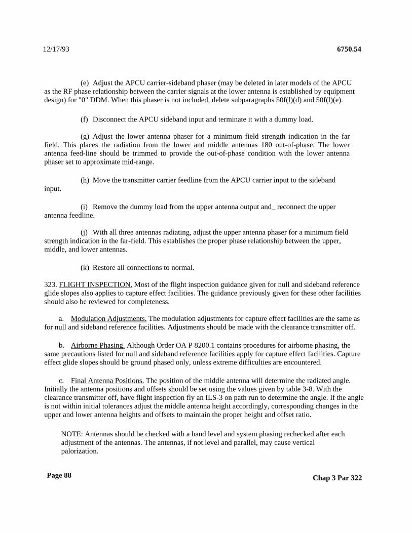
12/17/93 6750.54
(e) Adjust the APCU carrier-sideband phaser (may be deleted in later models of the APCU as the RF phase relationship between the carrier signals at the lower antenna is established by equipment design) for "0" DDM. When this phaser is not included, delete subparagraphs 50f(l)(d) and 50f(l)(e).
(f) Disconnect the APCU sideband input and terminate it with a dummy load.
(g) Adjust the lower antenna phaser for a minimum field strength indication in the far field. This places the radiation from the lower and middle antennas 180 out-of-phase. The lower antenna feed-line should be trimmed to provide the out-of-phase condition with the lower antenna phaser set to approximate mid-range.
(h) Move the transmitter carrier feedline from the APCU carrier input to the sideband input.
(i) Remove the dummy load from the upper antenna output and_ reconnect the upper antenna feedline.
(j) With all three antennas radiating, adjust the upper antenna phaser for a minimum field strength indication in the far-field. This establishes the proper phase relationship between the upper, middle, and lower antennas.
(k) Restore all connections to normal.
323. FLIGHT INSPECTION. Most of the flight inspection guidance given for null and sideband reference glide slopes also applies to capture effect facilities. The guidance previously given for these other facilities should also be reviewed for completeness.
a. Modulation Adjustments. The modulation adjustments for capture effect facilities are the same as for null and sideband reference facilities. Adjustments should be made with the clearance transmitter off.
b. Airborne Phasing. Although Order OA P 8200.1 contains procedures for airborne phasing, the same precautions listed for null and sideband reference facilities apply for capture effect facilities. Capture effect glide slopes should be ground phased only, unless extreme difficulties are encountered.
c. Final Antenna Positions. The position of the middle antenna will determine the radiated angle. Initially the antenna positions and offsets should be set using the values given by table 3-8. With the clearance transmitter off, have flight inspection fly an ILS-3 on path run to determine the angle. If the angle is not within initial tolerances adjust the middle antenna height accordingly, corresponding changes in the upper and lower antenna heights and offsets to maintain the proper height and offset ratio.
NOTE: Antennas should be checked with a hand level and system phasing rechecked after each adjustment of the antennas. The antennas, if not level and parallel, may cause vertical palorization.
Page 88 Chap 3 Par 322

12/17/93 6750.54
With the clearance transmitter on check for clearance signal effect on the glide path angle and width. A variation in glide angle with the clearance on indicates optimum phasing has not been established. Final adjustments to the path and width will be made with the clearance transmitter on.
d. Path Width Adjustments. The path width adjustments for the capture effect glide slope are the same as previously described for null and sideband reference glide slopes. As mentioned in subparagraph 50d final path width adjustments will be made with clearance transmitter on. At sites with irregular terrain, it may be extremely difficult to achieve a properly phased system. If difficulties are encountered, technical experts should be consulted for guidance.
e. Verification of Ground Phasing. C o n t ecground phasing can be established by an analysis of the airborne response to dephasing. Order OA P 8200.1 gives a checklist and procedures for phase verification. At capture effect facilities an N-type elbow (approximately 19 degrees) can be used for this check. One elbow should be placed in the middle feedline to retard the middle antenna and one elbow each in the upper and lower antennas to advance the middle phase. The path should widen symmetrically, the structure angle (190 microamp point) should drop symmetrically, and the angle should not change for a properly phased system.
f. Simulated Alarm Conditions. The alarm conditions used to set up the monitor for capture effect facilities are listed in subparagraphs 50f (1), 50f (2), and 50f (3):
(1) Wide alarm.
(2) Narrow alarm.
(3) Middle antenna attenuated.
(4) Middle antenna advance phase.
(5) Middle antenna retard phase.
(6) Upper antenna attenuated.
(7) RF power alarm.
324.-328. RESERVED.
Chap 3 Par 323 Page 89

12/17/93 6750.54
329. TUNEUP/SETUP FOR END-FIRE FACILITIES.
a. Antenna Positions. Unlike an image system the end-fire does not use a tower mounted antenna array. Instead the end-fire uses a course and clearance array made up of copper line sections with radiating sleeves mounted approximately 4 feet above the ground. The installation of the antenna array requires that a series of concrete piers be poured to accommodate the antennas. The position of these piers is based on an equation which is frequency dependent (see the end-fire instruction book TI 6750.162 for details) and therefore will vary slightly from site to site. Extreme care should be taken to survey these piers accurately. Although the antennas are mounted on umstrut and can be adjusted a small amount fore and aft, the development of the pattern in space is dependent on the individual radiating element position, and is not very forgiving to positional errors. Before installing the antenna in the frangible mounts the taper screws should be installed in the appropriate antenna sections as per the instruction books. The position of the antenna pedestals are critical to the structure and traverse performance of of the glide slope. Computer programs are used to position the pedestral due to the large number of radiating sleeves.
b. Transverse Performance. In order for the path angle to be approximately constant over the required azimuth sector, it is necessary that the front and rear antennas follow prescribed curves. The prescription for the curves is given with respect to figure 3-12 for the rear antenna. Point P is called the phase center of the array, midway between front and rear antennas, and is the point from which the path is assumed to originate. Point F is the focal point for the rear antenna, while point G is the virtual focal point for the front antenna. These focal points are displaced from the phase center a small distance toward their respective antennas for the purpose of optimizing the transverse flatness. In order to compute the antenna slot locations A, B, C, etc., it is necessary to have the slot voltage phase distribution. It is preferred to use a theoretical distribution for this, but if a measured distribution must be used, it should be carefully smoothed so that measurement and tolerance variations will not cause irregularities in the computed antenna curve. At midband, the phase advances from one slot to the next by 19.3 degrees in the straight sections, this value increasing gradually to about 22.2 degrees in the ends of the tapers. The calculation begins with an assumed length and direction AF, according to the desired antenna spacing and orientation. Length BF is obtained by adding to length AF a distance equivalent to the interslot phase advance. Length AB is the constructed slot spacing, known to be 15.000 inches. Thus, with all three sides of triangle ABF known, the location of slot B is specified.
Page 90 Chap 3 Par 329
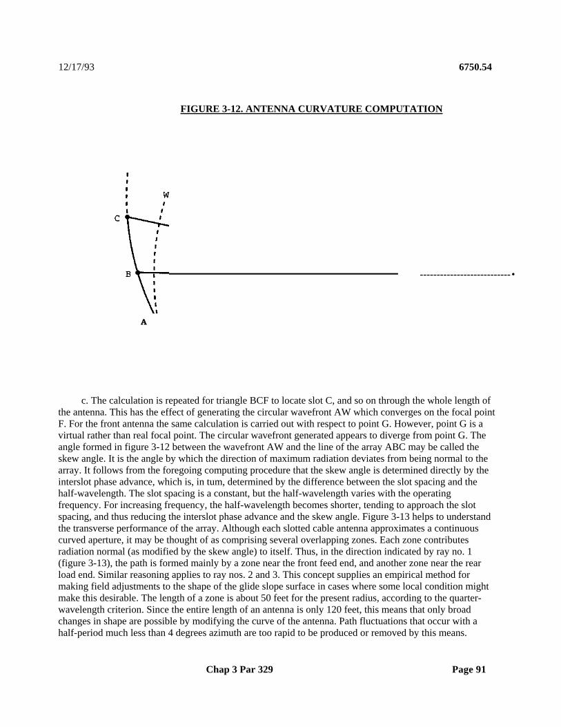
12/17/93 6750.54
FIGURE 3-12. ANTENNA CURVATURE COMPUTATION
A
c. The calculation is repeated for triangle BCF to locate slot C, and so on through the whole length of the antenna. This has the effect of generating the circular wavefront AW which converges on the focal point F. For the front antenna the same calculation is carried out with respect to point G. However, point G is a virtual rather than real focal point. The circular wavefront generated appears to diverge from point G. The angle formed in figure 3-12 between the wavefront AW and the line of the array ABC may be called the skew angle. It is the angle by which the direction of maximum radiation deviates from being normal to the array. It follows from the foregoing computing procedure that the skew angle is determined directly by the interslot phase advance, which is, in tum, determined by the difference between the slot spacing and the half-wavelength. The slot spacing is a constant, but the half-wavelength varies with the operating frequency. For increasing frequency, the half-wavelength becomes shorter, tending to approach the slot spacing, and thus reducing the interslot phase advance and the skew angle. Figure 3-13 helps to understand the transverse performance of the array. Although each slotted cable antenna approximates a continuous curved aperture, it may be thought of as comprising several overlapping zones. Each zone contributes radiation normal (as modified by the skew angle) to itself. Thus, in the direction indicated by ray no. 1 (figure 3-13), the path is formed mainly by a zone near the front feed end, and another zone near the rear load end. Similar reasoning applies to ray nos. 2 and 3. This concept supplies an empirical method for making field adjustments to the shape of the glide slope surface in cases where some local condition might make this desirable. The length of a zone is about 50 feet for the present radius, according to the quarter-wavelength criterion. Since the entire length of an antenna is only 120 feet, this means that only broad changes in shape are possible by modifying the curve of the antenna. Path fluctuations that occur with a half-period much less than 4 degrees azimuth are too rapid to be produced or removed by this means.
Chap 3 Par 329 Page 91
---------------------------•

12/17/93 6750.54
d. The simplest type of empirical change in transverse performance is to correct a constant lateral slope. This can be done by a rotation of either antenna, preferably pivoted on a post nearest the center, so as not to change the measured path angle too much. If the front antenna is ,rotated clockwise (load end forward in figure 3-13) the path will be made higher on the side toward the runway and lower on the side away from the runway. It is also feasible to rotate just one-half an antenna to raise or lower the path on one side while leaving it relatively unaffected on the other. The amount of motion required can be gauged by considering the ray in a direction of desired change. One inch of motion, averaged over the zone corresponding to that ray, should raise or lower the path indication about 50 micro-amperes, or .059 DDM. Movement in a direction to increase the distance from the other antenna increases the 150 Hz, and vice versa.
FIGURE 3-13. REGARDING AZIMUTH COVERAGE
RUNWAY EDGE
e. When making any adjustment to transverse performance, keep track of changes with a system of ground checking using a PIR. Readings should be taken a specific locations at various azimuths in
Page 92 Chap 3 Par 329
LOAD
•PHASE
CENTER
3

12/17/93 6750.54
the vicinity of the threshold. Such readings, kept on file, will show whether significant changes occur in the facility. Take the readings consistently. Keep the height constant using a unipod or a vehicular mounting in a consistent manner. The normal readings will, of course, be high in the 150 Hz. Nevertheless, a change in path angle will be reflected in the readings. Uniform changes in the traverse ground check indicate a phase change between the two main antennas. Non-uniform changes are an indication of a pedestal shift. The better method of ground checking the path requires taking the facility out of service and dropping the path to the ground by inserting the calibrated line length (Interface Unit PATH DOWN) in the Front Main Antenna feed. In this way, the glide path angle and shape are checked independently of the SBO power. In this condition, the DDM should be low in the sector of the main guidance antennas. The readings should be recorded for future reference.
f. Antennas and Monitor Feedlines. The feedlines for this array have hollow tubing surrounding the center conductor to accommodate pressurization of the antenna array. Care should be taken not to damage these cables during the installation. Additionally, when cutting the cables to install the connectors care should be taken not to allow metal fragments to fall back down into the tubing. These metal fragments can eventually be driven out into the inside the connector shorting the feedline. The equipment shelter is normally placed as nearly equidistant between the front and rear antennas as possible. This will help keep the feedlines to the antennas equal in length. The lengths for the following cable pairs should be the same length within one foot:
Front Feed to Rear Feed Front Monitor to Rear Monitor
Front Clearance to Rear Clearance
g. Transmitter Tuning. All transmitters are to be tuned as outlined in the instruction book for that particular type of equipment. Order 6750.49 should also be reviewed for additional information on transmitter tuning. The path (course) transmitter is tuned to a frequency 4 KHz above the assigned station frequency and the clearance transmitter 4 KHz below. This makes the frequency difference between the transmitters 8 KHz, equally disposed on either side of the assigned channel frequency.
330. FLIGHT INSPECTION. Although the EFGS is a non-image system many of the flight inspection procedures are the same as for a capture effect image system.
a. Airborne Phasing. Airborne phasing procedures and airborne phase verification procedures are not performed for the EFGS. The reason for this is because the radiated angle for the EFGS is dependent on the phase relationship between the front and rear main antenna arrays. Therefore the phasing for the main array antennas is fixed by adjusting the rear antenna phaser for the proper angle (a good rule of thumb for adjusting this phaser is that 10 degrees of phasing makes a difference of approximately 2/10 of a degree in the an Delaying the rear antenna phase will raise the angle. Conversely advancing the rear antenna phase will drop the path angle).
b. Final Antenna Position. Initially the antenna pedestals should be set by the taping radii given by the instruction books. Final antenna positions will be determined by flight inspection recordings/reports. In determining the proper antenna pedestal positions considerations should be given to transverse performance and glide path structure. Computer programs to deal with the
Chap 3 Par 329 Page 93

12/17/93 6750.54
complex geometry of the end-fire are being used in some regions to aid in process.
c. Path Width Adjustment. The path width for the EFGS is adjusted amplitude as described previously for other glide slope configurations.
d. Transverse Structure. Flight inspection for the EFGS requires that structure of the glide path be verified. These checks are done by flying an distance.
e. Clearance. Additional clearance runs are made at 5 and 8 degrees course for additional information.
f. Simulated Alarm Conditions. The alarm conditions used to set up facilities are:
(1) Wide alarm.
(2) Narrow alarm.
(3) High angle alarm.
(4) Low angle alarm.
(5) Main SBO advance phase.
(6) Main SBO retard phase.
(7) RF power alarm.
331.-333. RESERVED.
Page 94 Chap 3 Par 330
the pedestal positioning
by varying the sideband
the horizontal or transversearc at the final approach fix
each side of the localizer
the monitor for end-fire

12/17/93 6750.54
CHAPTER 4. MARKER TECHNICAL DETAILS
400. INTRODUCTION. ILS associated fan markers, or marker beacons (MB), are sited along the approach path to provide a rough indication of an aircraft's distance from the runway, and to indicate significant points along an instrument approach path. A complete ILS installation for Category II or III approaches will include three markers.
401. LOCATION OF THE ILS MARKERS. An outer marker (OM) is typically located 4 to 7 nautical miles from the runway approach threshold; this location normally coincides with the ILS glide slope intercept point. The middle marker (MM) is located approximately 3,500 feet from the runway approach threshold; this distance normally coincides with the decision height (DH) point for Category I operations (200 feet above the touchdown zone elevation). The inner marker (IM) is only installed for Category II and III ILS approaches, and is located approximately 1,000 feet from the runway approach threshold, coinciding with the nominal Category II DH of 100 feet. Refer to Order 6750.16 for additional information.
402. TRANSMIT SYSTEM. Marker beacons transmit an upward cone of information at 75 MHz. (An exception to this exists for closely spaced parallel runways where adjacent markers might cause incorrect indications. In this case the marker frequencies may be offset from 75 MHz by ±4 KHz.) Each marker is amplitude modulated by an audio tone which is Morse code keyed. Both the audio tone frequency and keying are distinctive according to the marker location. Additionally, the aircraft receiver uses differently colored lights to identify the specific marker. Table 4-1 gives a summary of this.
TABLE 4-1
MARKER INDICATOR KEY
MARKER TONF FREQUENCY KEYING CODE COLOR
Outer 400 Hz - - - - Purple
Middle 1300 Hz _ _ Amber
Inner 3000 Hz ...... White
Back Course 3000 Hz
White
Chap 4 Par 400 Page 95
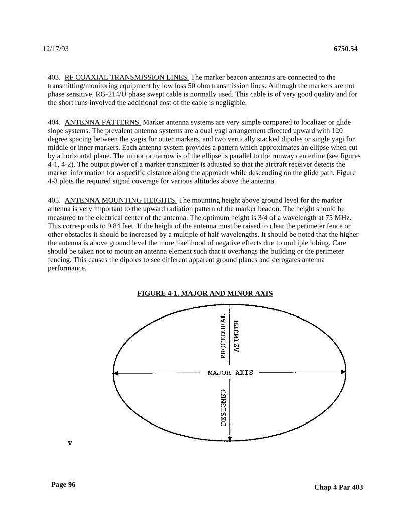
12/17/93 6750.54
403. RF COAXIAL TRANSMISSION LINES. The marker beacon antennas are connected to the transmitting/monitoring equipment by low loss 50 ohm transmission lines. Although the markers are not phase sensitive, RG-214/U phase swept cable is normally used. This cable is of very good quality and for the short runs involved the additional cost of the cable is negligible.
404. ANTENNA PATTERNS. Marker antenna systems are very simple compared to localizer or glide slope systems. The prevalent antenna systems are a dual yagi arrangement directed upward with 120 degree spacing between the yagis for outer markers, and two vertically stacked dipoles or single yagi for middle or inner markers. Each antenna system provides a pattern which approximates an ellipse when cut by a horizontal plane. The minor or narrow is of the ellipse is parallel to the runway centerline (see figures 4-1, 4-2). The output power of a marker transmitter is adjusted so that the aircraft receiver detects the marker information for a specific distance along the approach while descending on the glide path. Figure 4-3 plots the required signal coverage for various altitudes above the antenna.
405. ANTENNA MOUNTING HEIGHTS. The mounting height above ground level for the marker antenna is very important to the upward radiation pattern of the marker beacon. The height should be measured to the electrical center of the antenna. The optimum height is 3/4 of a wavelength at 75 MHz. This corresponds to 9.84 feet. If the height of the antenna must be raised to clear the perimeter fence or other obstacles it should be increased by a multiple of half wavelengths. It should be noted that the higher the antenna is above ground level the more likelihood of negative effects due to multiple lobing. Care should be taken not to mount an antenna element such that it overhangs the building or the perimeter fencing. This causes the dipoles to see different apparent ground planes and derogates antenna performance.
FIGURE 4-1. MAJOR AND MINOR AXIS
Page 96 Chap 4 Par 403
V

12/17/93 6750.54
FIGURE 4-2. REQUIRED SIGNAL STRENGTH AND COVERAGE
B B
A-A1 - ELECTRONIC LOCALIZER ON-COURSE
B-B1 - EDGE OF LOCALIZER COURSE SECTOR WIDTH (150 uA/150 Hz OR 150 uA/90 Hz)
Chap 4 Par 405 Page 97
AREA WHERE SIGNAL IS2 MILLIAMPS OR GREATEF

12/17/93 6750.54
FIGURE 4-3. COVERAGE VS. HEIGHT ABOVE MARKER
HEIGHT ABOVE MARKER
DISTANCE FROM MARKER
406. MARKER BEACON ADJUSTMENTS AND FLIGHT INSPECTIONS. Other than audio and carrier frequencies, the only transmitting equipment adjustments for marker beacons are the output power level and tone modulation percentage. Changing either the output power or the modulation percentage will effect the width of the detected marker indication along the runway centerline. The flight inspection aircraft measures the distance along the runway centerline during which 2 milliamps of signal is received. Flight inspection will also determine that 2 milliamps of signal is received briefly when the aircraft flies at the right and left half edges of the localizer course width (see figure 4-2). This confirms that the major is of the pattern has sufficient width.
Page 98 Chap 4 Par 406
MINOR AXIS PARALLEL TO CENTERLINE
ACTUAL MARKER WIDTHS VARY SOMEWHAT WITH ANTENNA TYPES
MAJOR AXIS PERPENDICULAR TO CENTERLINE----•
4000 2000 2000 4000

12/17/93 6750.54
CHAPTER 5. COMPASS LOCATOR SYSTEMS
SECTION 1. TECHNICAL CHARACTERISTICS
500. SYSTEM DESCRIPTION. A NDB system allows properly equipped aircraft to determine aircraft bearing and "home in" on the NDB station. Those NDB facilities collocated with ILS markers are known as compass locators. The NDB radiates a non-directional, vertically polarized signal in the low to medium frequency band (190 to 535 KHz). The NDB signal is modulated with a 1020 Hz tone, keyed with a Morse code identifier to provide positive station identification. In some cases, voice modulation is also present to provide voice transmissions (e.g., transcribed weather broadcasts) or voice identifiers.
NDB systems collocated with the OM are known as compass locator-outer-marker (LOM) facilities and are the most common in the FAA. Those collocated with the MM are called compass locator-middle-marker (LMM) facilities. NDB systems are used for missed approach guidance, nonprecision approaches, and most important for ILS, as a way to transition from the en route environment to the localizer course. Many ILS procedures are not authorized in instrument flight rules (IFR) weather if the associated LOM is out of service. In that particular case, the LOM provides the only IFR guidance to the pilot to use in finding the localizer course.
NDB systems are classified by their intended use. Each type of system has different service volume (coverage or usable distance) requirements. A COMLO requires a usable distance of 15 nautical miles, and has an RF power output of 25 to 50 watts. No other classifications will be discussed here.
The major components of an NDB system include a transmitter, transmission lines, an antenna, and monitor equipment. The monitor provides monitoring for antenna current, and for loss of or constant ident. Some systems use voltage monitoring, which does not provide a good representation of the radiated signal-in-space.
NDB antennas are series resonant circuits, which include a tuning coil, a downlead radiator, and various types of capacitive "tophats." These tophats may be wires strung between wooden poles ("flat top T") or may have the appearance of a "wagon wheel." The tuning coil provides the inductance needed to resonate the antenna circuit. The "top hat" portion of the antenna does not radiate, but serves to reduce the inductance or "L" needed to resonate the antenna circuit (and therefore reduce resistive losses), and to raise the effective height of the current in the vertical downlead. The radiated power of the antenna is directly related to the RF current in the vertical downlead.
When the antenna circuit is resonated, the input impedance is purely resistive, and consists of ground losses, copper (or connection) losses, and a radiation resistance. The radiation resistance represents that portion of the antenna which radiates, and is solely dependent upon the ratio of the electrical height of the downlead to the wavelength. Since the wavelength at NDB frequencies is extremely long (approximately 1,840 feet at 535 KHz) and the downlead is usually on the order of 25 feet, NDB antennas exhibit very poor efficiencies.
At NDB frequencies, signals radiate via a ground wave, and NDB receivers respond to the induction fields created by the propagation of this ground wave. NDB antennas have a ground
Chap 5 Par 500 Page 99

12/17/93 6750.54
counterpoise, which consists of a copper ring around the antenna, with radials extending out in all directions from the central ring. A good ground plane is needed to provide a return path to the earth for the antenna current.
The power radiated by an NDB antenna is directly related to both the radiation resistance and the RF current in the antenna circuit. Since the radiation resistance is solely dependent upon downlead length (for a particular frequency), the radiated power will vary in direct proportion to the (square of) the average antenna current. If the current varies in the antenna circuit, then the radiated power will vary.
When the solid-state NDB equipment was purchased, the transmitter used voltage control and voltage monitoring, and no way to measure the current in the antenna was provided. Since the resistance of an NDB antenna can vary (ground resistance will vary with moisture content, etc.), the current could then vary since the transmitter applied a constant voltage to the antenna circuit. This is highly undesirable, since varying the antenna current will cause the radiated power to vary. If an antenna experiences icing, the resistance of the antenna will increase, and the current will decrease. If the resistance gets high enough, the current may well approach zero. When this order was published, projects were underway to modify all NDB systems to provide for constant current control and monitoring. Make sure to note whether or not your particular NDB has been modified in this way.
Page 100 Chap 5 Par 500

12/17/93 6750.54
SECTION 2. INSTALLATION INSTRUCTIONS
501. PURPOSE. The purpose of this section is not to provide general guidance on installation of NDB systems. Such guidance is provided in Order 6750.4, Non Directional Beacon Installation Standards Handbook. This section will point out any requirements not specified by that order which apply solely to ILS associated NDB systems.
502. GENERAL. The only requirement that applies solely to ILS associated NDB systems is the requirement for battery backup. Order 6950.2, Electrical Power Policy for National Airspace System Facilities, requires that LOM and LMM facilities have a (minimum) 4-hour battery backup capability in case of a commercial power failure.
503.-504. RESERVED.
Chap 5 Par 501 Page 101 (and 102)


12/17/93 6750.54
CHAPTER 6. OTHER INFORMATION
SECTION 1. TECHNICAL CHARACTERISTICS
600. REMOTE MONITOR AND CONTROL. The need for remote monitoring and control of a particular ILS system is determined by Air Traffic. Remote monitoring consists of a "go/no-go," red light/green light type of indication to Air Traffic personnel. Remote control capabilities usually include a remote reset, and an on/off type of capability. In the case of a runway or airport with several ILS systems, an interlock capability may be provided. Interlocks will be discussed in detail later in this chapter. Remote monitoring is routinely provided for all ILS systems. Marker facilities are normally monitored only for Category II and III facilities. Remote monitor systems generally consist of two parts, a remote monitor unit and a status unit. The remote monitor unit receives and processes the status information from the localizer and glide slope, and the status unit displays that information to Air Traffic. The two most common types of remote monitor units are the "landline remote monitor and control unit" and remote monitor receivers. The landline type control unit uses a dedicated hardwire line to receive status information from the localizer and glide slope. The remote monitor receivers use "through the air monitoring." Remote monitor receivers include a built in VHF or UHF receiver and an external antenna. These receivers monitor the ILS frequencies for the presence of the carrier signal, and are set to indicate an ILS alarm when the signal strength drops below a preset threshold (this threshold is variable). Control capabilities are included on most landline remote monitor and control units, but no control capability is provided in the remote monitor receivers. The remote monitor unit is typically sited at the location where the system will be monitored. Typical locations include air traffic control towers (ATCT), flight service stations (FSS), etc. This location will vary depending upon the configuration of the airport. The remote status unit will be located to provide status indications to air traffic (or other FAA personnel). Examples of typical locations are the ATCT cab or Terminal Radar Approach Control (TRACON). One set of remote monitor and control equipment is normally required for each ILS system, but some designs currently in use will handle several ILS systems on a consolidated status display.
Loss of remote monitoring capabilities due to a failure of the landline or monitoring equipment will likely have little direct impact on the users of that particular ILS (unless of course the ILS has failed also). It may affect other IFR flights who wish to use that particular airport (and ILS) as an alternate destination when filing an IFR flight plan. FAA policy requires that an ILS system be remotely monitored in order to be used as an alternate airport when filing an IFR flight plan.
601. REMOTE MAINTENANCE MONITORING. The purpose of RMM is to provide capabilities for the ILS technician to perform maintenance operations remotely. While RMM will provide remote monitor and control capabilities, at this time, it will not normally replace the remote monitor and control equipment used to provide Air Traffic with status information and control capabilities. RMM is designed primarily for use by airway facilities personnel. RMM systems normally provide the capability for turning the system on and off, resets, and will provide for measurement of all monitored parameters remotely. Some RMM systems will also provide capability to adjust equipment parameters (e.g., sideband power) remotely. RMM can be used to remotely accomplish many maintenance tasks normally performed at the site. In addition, FAA specifications for RMM systems include capabilities for monitoring of environmental parameters such as building temperature, etc. RMM systems will nominally consist of a central processing unit, a display unit (computer monitor), communications equipment (e.g., modem), and interface hardware (for connection to the ILS equipment). RMM
Chap 6 Par 600 Page 103
12/17/93 6750.54
equipment can be integrated into the ILS equipment design, or may be retrofitted to existing ILS equipment. The FAA has procured a system called the A S . These systems are to be installed on Mark 1 D m o d e l equipments. The ARMS system provides remote monitor and very limited control capabilities. No capability is provided for making equipment adjustments (sideband power, etc.), but remote readings of monitor indications (course, path channels, etc) are provided. The ARMS system does provide the capability for accessing ILS status information through the maintenance processor system (MPS). This system will allow the Maintenance Control Center (MCC) technicians to have remote status information.
602. ILS INTERLOCK SYSTEMS. Multiple ILS systems installed on the same airport or runway may require interlock systems to prevent multiple ILS systems from operating simultaneously. The most common situation requiring interlock equipment is a runway which has a localizer on each end. In this case, it is important to have only one localizer radiating at any one time. Glide slopes are not normally interlocked, unless they share a common frequency or an interference problem exists between the two systems. Other situations, such as two ILS's sharing a common frequency which serve the same airport will require an interlock, but that situation is unusual. Requirements for ILS interlocks are contained in Order 6750.16, Siting Criteria for ILS Systems. Interlock equipment is usually located in the ATCT, and may be integrated with the remote monitor and control units. Many regional and site specific designs have been used for interlocking ILS's. Information on these designs should be available in the facility drawings and other records. Appendix 1 of this order contains information on interfacing FA-9427 type interlock equipment to various types of ILS hardware.
603. FAR-FIELD MONITOR. Category II and III localizer systems employ a far-field monitor to provide for signal integrity monitoring (in addition to the integral monitors). Far-field monitors are used to monitor changes in the localizer course due to factors external to the antenna array (i.e., reflections from taxiing aircraft) and other changes which would not affect the integral monitors, but would cause signal changes in the far field. Because the far-field monitor will be affected by taxiing aircraft and other temporary signal aberrations, these monitors provide discrete time delays before initiation of an alarm indication remotely. Far-field monitor equipment consists of one or more antennas, a localizer receiver, and alarm/control circuitry. Landlines are used to link the far-field monitor with the localizer station to provide for shutdown and/or maintenance alert action. The far-field monitor is usually located on centerline at or near the IM or MM shelter.
604.-610. RESERVED.
Page 104 Chap 6 Par 601

6750.54 12/17/93
SECTION 2. ELECTRONIC INSTALLATION
611. GENERAL. This section will highlight important information regarding the installation of the various types of equipment discussed in this chapter.
612. EQUIPMENT LAYOUT AND INSTALLATION. The glide slope equipments should be installed in their respective positions as depicted by the appropriate floor plan in the equipment instruction book or as per regionally adapted drawings. The equipment rack shall be bolted to the floor with a minimum of three bolts or lag screws to prevent tipping or movement. Any adjacent racks and cabinets shall also be bolted together in at least three places to ensure rigidity.
a. Wiring. The wiring from the entrance switch to the distribution cabinets and all building lighting and outlet circuits shall conform to the National Electrical Code with regard to size and color coding. Wiring from the distribution cabinets to electronic equipment, the rack wiring, and the in rack wiring shall conform to the current applicable drawings. Adequate grounding systems and proper shielding shall be installed as specified on the drawings. A number 6 AWG bare copper ground wire shall be used to bond all equipment cabinets to the station ground.
b. Intrarack Wiring. All power and control wiring and RF cables will be routed through conduits provided with the shelter. Intrarack wiring between the transmitters and adjacent racks will run through knockouts located between them.
613. REMOTE MONITOR AND CONTROL.
a. Landline Monitor Equipment. The guidance contained in the instruction books for various landline equipment is generally considered adequate. Installation personnel should give consideration to providing spare landline pairs. These spares will provide backup lines in case of cable deterioration. Some installations are now using microwave links, or even fiber optics to provide for linking of the monitor information from the ILS equipment to the monitoring location. Use of alternate methods such as these (when feasible) are encouraged, since landlines tend to be prone to damage from on-airport construction or animals.
b. Remote Monitor Receiver Equipment. The use of a remote monitor receiver requires that adequate signal strength be present at the monitor receiver location. In some cases, it may be necessary to provide increased signal strength at the receiver location to obtain reliable monitoring. For example, the monitor receiver may be located behind the glide slope some distance away, where little signal strength is present. One method of increasing signal strength for the monitor receiver is to radiate a small amount of unmodulated carrier using a directional antenna oriented towards the monitor receiver. A sample can be obtained by installing a directional coupler or other device between the exciter and the modulator. A yagi antenna cut for the proper frequency is commonly used for this purpose. If this method is used, the antenna shall be radiating normally during the commissioning flight inspection. The installation of the antenna and sampling hardware should be noted in the facility drawings and other records.
Chap 6 Page 105 Par 611

6750.54 12/17/93
614. REMOTE MAINTENANCE MONITORING. The equipment instruction books for RMM equipment provide adequate installation guidance. When installing RMM hardware, security should be a prime consideration. Some systems do not have built in security measures to prevent an unauthorized user from accessing the RMM system. If the RMM hardware does not provide security measures, the designer should have considered providing some measure of security. For example, if an external modem is used with the RMM system, this modem could be replaced with a modem that has a "callback" feature. This feature allows the user to program in one or more numbers which are authorized to use the modem. The user calling the modem then can dial up the facility, and then the modem will call the user's computer back a short time later. Consult Order 6000.15 for further guidance on security requirements.
615. ILS INTERLOCK SYSTEMS. The installation guidance in the various instruction books is considered adequate, and no further guidance is provided here. See appendix 1 for additional information on interfacing interlock systems with existing ILS hardware.
Page 106 (and 107) Chap 6 Par 614

6750.54 12/17/93
Page 416
APPENDIX 1. MULTIPLE ILS INTERLOCK SYSTEM
1. GENERAL. The basic multiple ILS Interlock System is made up of a Selector/Indicator, FA-9427/1, installed at the tower, and a Control Unit, FA-9427/2, installed at each site to be controlled. In this appendix, the method of connection the FA-9427 interlock equipment to various types of localizers, glide slopes, and marker beacons is presented.
2. EQUIPMENT DESCRIPTION.
a. FA-9427/1 Selector Indicator. The FA-9427/1 is 10" wide x 8" deep (+connectors) x 6" high (+ switches). Two 24-terminal ribbon connectors with individually keyed shells are provided. A 5' AC power cord, on a strain relief bushing, with three prong plug for 117V as is included. Maximum power requirements is 100 watts. The selector/indicator has the following functions:
(1) Major functions.
(a) Enable the transmitters on one runway and disable the transmitters on the other runway.
(b) Indicate the status of the operating equipment.
(2) Minor functions.
(a) Disable all transmitters on both runways, with selector switch in center position.
(b) Reset switches for individual equipment.
(c) Silence switch for alarm buzzers.
b. FA-9427/2 Control Unit. The FA-9427/2 is 1-1/2" wide x 5" deep (+ relay) x 3-3/8" high (+ switches). One 19-terminal MS connector is provided. The unit must be supplied with +12V DC power supply are included, consisting of: 6' AC power cord, 5A fuse, fuse block, transformer, and rectifier bridge. Figure 6B illustrates the 12V DC power supply. The control unit has a relay that will open or close the transmitter control line, provide a path for reset, display disable/enable lights, and provide a bypass switch.
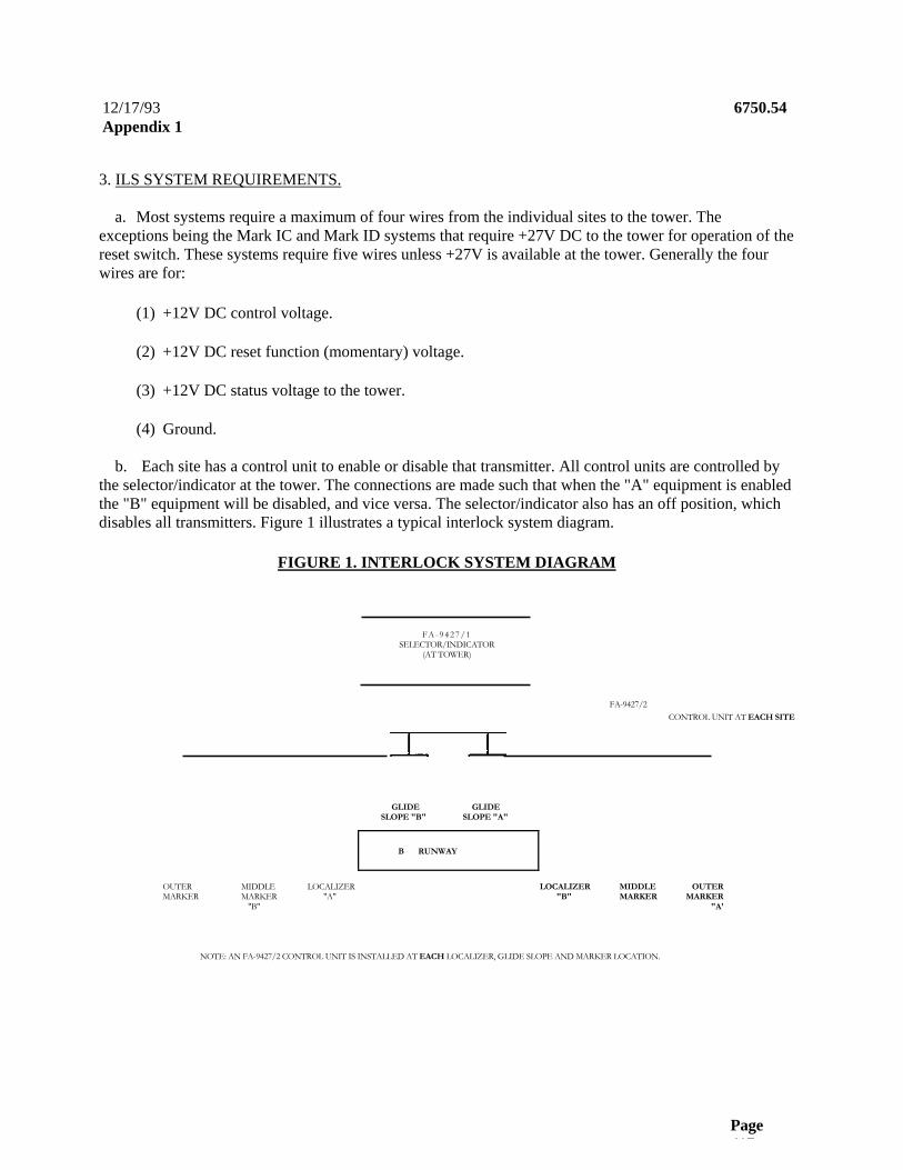
12/17/93 6750.54 Appendix 1
Page 417
3. ILS SYSTEM REQUIREMENTS.
a. Most systems require a maximum of four wires from the individual sites to the tower. The exceptions being the Mark IC and Mark ID systems that require +27V DC to the tower for operation of the reset switch. These systems require five wires unless +27V is available at the tower. Generally the four wires are for:
(1) +12V DC control voltage.
(2) +12V DC reset function (momentary) voltage.
(3) +12V DC status voltage to the tower.
(4) Ground.
b. Each site has a control unit to enable or disable that transmitter. All control units are controlled by the selector/indicator at the tower. The connections are made such that when the "A" equipment is enabled the "B" equipment will be disabled, and vice versa. The selector/indicator also has an off position, which disables all transmitters. Figure 1 illustrates a typical interlock system diagram.
FIGURE 1. INTERLOCK SYSTEM DIAGRAM
F A - 9 4 2 7 / 1 SELECTOR/INDICATOR
(AT TOWER)
FA-9427/2 CONTROL UNIT AT EACH SITE
GLIDE GLIDE SLOPE "B" SLOPE "A"
B RUNWAY
OUTER MIDDLE LOCALIZER LOCALIZER MIDDLE OUTER MARKER MARKER "A" "B" MARKER MARKER
"B" "A'
NOTE: AN FA-9427/2 CONTROL UNIT IS INSTALLED AT EACH LOCALIZER, GLIDE SLOPE AND MARKER LOCATION.

6750.54 12/17/93 Appendix 1
Page 418
4. TECHNICAL DESCRIPTION.
a. Selector/Indicator Block. The selector consists of 2-4P3T switches ganged together. Each site is connected to individual sections of the switches. See figure 2. The indicator portion is made up of eight identical channels. Each channel has an input transistor to drive a relay. When the relay is deenergized (site off the air) both the red light and the alarm buzzer will be on. The alarm silence will turn off the alarm buzzer, but leave the red light on. When the site is on, the relay will be energized and green light on. A reset switch is provided for each site. The switch may be connected to ground, a voltage, or a short circuit, depending on the site requirements.
FIGURE 2. SELECTOR/INDICATOR BLOCK DIAGRAM
0
SELECTOR 00 ENABLE 'A"/DISABLE •B•
OFF (DISABLE ' A ' AND 'B•) REPEATED FOR
0 ENABLE "B•/DISABLE 'A• EACH SITE
l -------------------------------------- _ J
l_-
RESET H L-----------------------------------
REPEATED FOR EACH SITE
-------------------------- J
ALARM SILENCE
TO STATUS ALARM BUZZER IN TOWER
------------------------------------------ ~ - 1
The alarm silence switch silences the buzzers on other status indicator units at the tower. The FA-9427/1 Multiple ILS Interlock Selector/Indicator Schematic diagram is shown in figure 1.
STATUSINPUT
INDICATOR
REPEATED FOR EACH SITE

12/17/93 6750.54 Appendix 1
Page 419
b. Control Unit Block. When the Selector/Indicator, FA-9427/1, is switched to enable a site, the voltage on the control line energizes the relay. This enables the transmitter control, turns on the "Enable" green light, and completes the "reset" line path. The relay can also be energized by operating the bypass switch, which will also tum on the bypass light. See figure 3. A status voltage from the transmitter is fed back to the selector/indicator unit. If there are dual status lines from the transmitter, diodes in the control unit should be used for isolation. The +12V DC can be obtained from supplied components, or from existing power supplies at the site. The FA-9427/2 Multiple ILS Interlock Control Unit Schematic diagram is shown in Figure 6A. A schematic diagram of the +12V DC power supply is shown in Figure 6B.
FIGURE 3. CONTROL UNIT BLOCK DIAGRAM
DISABLE
CONTROL LINE FROM FA 9247/1
ALARM BUZZER
RELAY
BYPASS
0 + 12 V dc
FROM RESET SWITCH IN FA 9427/1
TO STATUS INPUT OF FA 9427/1
TRANSMITTER CONTROL
RESET TERMINAL
/ STATUS FROM \TRANSMITTER

6750.54 12/17/93 Appendix 1
Page 420
5. SYSTEM INSTALLATION. Refer to the following figures (in this appendix) for interconnecting diagrams of the various ILS configurations.
Figure 4. Installation Wiring Table. Figure 5. Multiple ILS Interlock Selector/Indicator Schematic Diagram. Figure 6A. Multiple ILS Interlock Control Unit (FA-9427/2) Schematic Diagram. Figure 6B. +12V DC Power Supply Schematic. Figure 7. Mark 1A (Wilcox) Localizer and Glide Slope.Figure 8. Mark 1B (AIL) Localizer and Glide Slope. Figure 9. Mark 1C (Wilcox) Localizer and Glide Slope. Figure 10. Mark 1D (Wilcox) Localizer and Glide Slope.Figure 11. AN/GRN-27 CAT II )T.I.) Localizer and Glide Slope. Figure 12. FA-5791 Solid-State 75 MHz Marker. Figure 13. Mark IA (Wilcox) FA-8030-3 75 MHz Marker. Figure 14. FA-8102, 3 and 4 75 MHz Marker. Figure 15. Mark 1B (AIL) 75 MHz Marker. Figure 16. Mark 1C (Wilcox) FA-8831-6 75 MHz Marker. Figure 17. AN/GRN-26 (T.I.) 75 MHz Marker.Figure 18. AN/GRN-28 (T.I.) 75 MHz Marker.
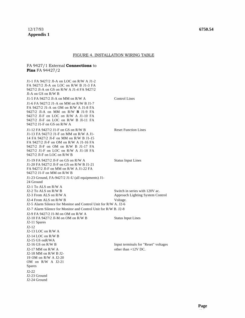
12/17/93 6750.54 Appendix 1
Page 421
FIGURE 4. INSTALLATION WIRING TABLE
FA 9427/1 External Connections to Pins FA 94427/2
J1-1 FA 9427/2 Jl-A on LOC on R/W A J1-2 FA 9427/2 Jl-A on LOC on R/W B J1-3 FA 9427/2 Jl-A on GS on R/W A J1-4 FA 9427/2 Jl-A on GS on R/W B J1-5 FA 9427/2 Jl-A on MM on R/W A Control Lines J1-6 FA 9427/2 J1-A on MM on R/W B J1-7 FA 9427/2 J1-A on OM on R/W A J1-8 FA 9427/2 Jl-A on MM on R/W B J1-9 FA 9427/2 Jl-F on LOC on R/W A J1-10 FA 9427/2 Jl-F on LOC on R/W B JI-11 FA 9427/2 J1-F on GS on R/W A J1-12 FA 9427/2 J1-F on GS on R/W B Reset Function Lines J1-13 FA 9427/2 J1-F on MM on R/W A J1-14 FA 9427/2 Jl-F on MM on R/W B J1-15 FA 9427/2 Jl-F on OM on R/W A J1-16 FA 9427/2 Jl-F on OM on R/W B J1-17 FA 9427/2 J1-F on LOC on R/W A J1-18 FA 9427/2 Jl-F on LOC on R/W B J1-19 FA 9427/2 Jl-F on GS on R/W A Status Input Lines J1-20 FA 9427/2 Jl-F on GS on R/W B J1-21 FA 9427/2 Jl-F on MM on R/W A J1-22 FA 9427/2 J1-F on MM on R/W B J1-23 Ground, FA-9427/2 J1-U (all equipments) J1-24 Ground J2-1 To ALS on R/W A J2-2 To ALS on R/W B Switch in series with 120V ac. J2-3 From ALS on R/W A Approach Lighting System Control J2-4 From ALS on R/W B Voltage. J2-5 Alarm Silence for Monitor and Control Unit for R/W A. J2-6 J2-7 Alarm Silence for Monitor and Control Unit for R/W B. J2-8 J2-9 FA 9427/2 J1-M on OM on R/W A J2-10 FA 9427/2 Jl-M on OM on R/W B Status Input Lines J2-11 Spares J2-12 J2-13 LOC on R/W A J2-14 LOC on R/W B J2-15 GS onR/WA J2-16 GS on R/W B Input terminals for "Reset" voltages J2-17 MM on R/W A other than +12V DC. J2-18 MM on R/W B J2-19 OM on R/W A J2-20 OM on R/W A J2-21 Spares J2-22 J2-23 Ground J2-24 Ground

6750.54 12/17/93 Appendix 1
Page 422
FIGURE 5. MULTIPLE ILS INTERLOCK SELECTOR/INDICATOR SCHEMATIC DIAGRAM (SHEET 1 OF 2)
SELECTOR
1. COY ECT 70.12 Vac FOR MARK I aA.40 ANAFW-27 ANO TUBE•TYPE LOCAIIZERS AND GLIDE SLOPES
2. CONNECT TO STATION «t8 V aC
FOR•RECONPQURED TUBE-7YPE'.
10 O
O.S M X •A•
M . M . $ O.M. W
O.M. B ALS •A•
ALS'6
P,o.a
FROM ALS V FRp4ALS •A•
IN4384
12 CR1 13
22 CR27 23 • __ II 0
II.14 04I O 5 U
B CR2 2 0 _________• __ N - o
111914
8:
FA 9427A P103
LOC•8• O.S. A•
CR12~ 1 1 10 C M 11
w~ :o -• V o / 12 \ 111914
0 a 1 / 2 14 CM a . o • N 0 15 o
3 INa14 1 CONNECT TO .12 V Oc FOR
4 : ALL MARKERS O . O / • • I♦ U 8 IN914
6I_______________________ 0 5 3 CM 4 7 O
CAR IN4384
CS CR
d,
.R
1. MAPo(4 0NNE0T TO GROUND. 2. MARK b. 00 NOT USE a MAR 0 0.80. CONNECT 10.27 V OC w CAT II (CRN-271. CONNECT 10 .12 V OC S TUBE TYPE IDI& TYPE). CONNECT TO O W . • RECOIaFlGURED TUBE-TYPE, 001107 USE
1. NARK IaSIGRN4M M M CNNECT T0 .12V ft 2. MARK I C.0 CONNECT T0.27 V OC. 3. TUBE-TYPE MARKERS.00 NOT USE
DS19 POWER ONGREEN
.,2VOC
CR19
120V } ( CRZO M )

12/17/93 6750.54 Appendix 1
Page 423
LOC•A RE
LCC$RESEf
MS.' A O.S
M.M.'8• RESET
OM•A•RESETI OM •B• RESET 161
P.OJ2 51
SILENCE {SIL SYSTEM •A•
ALAR M 0 ALARM
SILENCE SILENCE FOR 1 3YSTEM'B•
(
Fl5AMP
120 vac i t (TNREEfRONG PLUG) 'CV

6750.54 12/17/93 Appendix 1
Page 424
FIGURE 5. MULTIPLE ILS INTERLOCK SELECTOR/INDICATOR SCHEMATIC DIAGRAM (SHEET 2 OF 2)

12/17/93 6750.54 Appendix 1
Page 425
FIGURE 6A. MULTIPLE ILS INTERLOCK CONTROL UNIT (FA-9427/2) SCHEMATIC DIAGRAM
.... K7 .
m
1 R ) 2
J1J1
4 1 6 7 CR11N014 t 1 0 0 5
C. SS AC AO
. PI
E W ♦ S, Mann
to 1 0 0 0 1 t
1 1 4- 0 - 4 1 2
o z 1 (~in1 os1 a s 0 •,zv o z N Nets
to Z00
R..~ AA JIM
tt 11 \ a
AO l e J , - 0 1 1 3 u u t S
41-0 f t A . u . e p .
J I J 410
I S
AA S1.w OWw
n« 0'14 : I w 1 .
A A 21 '
416
n - r _ 1 C 2
FIGURE O . +12 V DC POWER SUPPLY SCHEMATIC
(Mounted Separate)
F1
r - > m. 5A
120 Vac
T1 1 8
2 9
3 0 - ! ~-•) J1-V 4
5 0 ______________ 10 6 )) (jj(
o ____) \ 7 11
AC 1 CR 4 + b +12V
P1-T
y AC 2
-12V P1-N

6750.54 12/17/93 Appendix 1
Page 426
FIGURE 7. MARK 1A (WILCOX) ILS (LOCALIZER AND GLIDE SLOPE) SCHEMATIC DIAGRAM
12 -
6 11 0 0 F
2K4 R Cam 2-3
CR3 M 2K4 - - - - - 0 - _ - _ - - - -
ro -of f CR2
- - - - - - - - - - - - - - - - - - - - - - - - - - - - - - - - - - - - - - - - - - - - - - - - - - - - - - - - - - - - -
FA 9427/1. SeledorMdicator
- - - - - - - - - - - - - - - - - - _ s a l s a « Sw.
(J1:1-B)
- - - . J1-23
Omer 3190 ro ground
Rest Swaaf (Jt:416)
_ _ -< Statue Input (J1:17.22&J2410)
- - - - - - - - - - - - - -
NOTE: When the station is enabled, 25V DC will be supplied through K1:7 to 6 to provide turn-on power for the transmitter. Also, the "Reset" path is completed, so the station status can be stepped through its sequence, by K1:13 to 12. The status indicator line, 2K4 cam 2-1, provides voltage to the FA-9427/1 when main is on; if station has dual transmitters, 2K4 cam 2-3 should be connected to FA-9427/2-R and isolate P and R with CR2 and 3. K1 can be energized at the site by operating Si to the bypassed position.
fa 9472/2. Control U it
- - - - - - - - - - - - - - - - - - - - - - - - - - - - - - - - - - - - - - K1 4
C , ________________ OS1
R2 CR A (pp C.= 2 4 Y ,
R a n a l 3 Bypass
I
Preee.R S i te Contrd Equipment
U
2543- __-

12/17/93 6750.54 Appendix 1
Page 427
FIGURE 8. MARK 1B (AIL) ILS (LOCALIZER AND GLIDE SLOPE) SCHEMATIC DIAGRAM
Presets S i te FA 9427/2 , Contro l Un i t FA 9427/1 Cont ro l Equ ipment Selector/Inoeator
- - - - - - - - - - - - - - - - - - - - - 3 K t 4 R1 A ------------------------------------------------
1 1 5 V ae 8 -
U L ' - -8 <J1 .23 0 E
NOTE: When FA 9427/2 is enabled, K1 will be energized completing the 115V AC circuit through K1:7 to 6. The reset circuit is not used, since the station is automatically set to main when the 115V AC line is broken. The status line, TP1, provides voltage to FA-9427/1 when the main is on; if the station has dual transmitters TP2 should be connected to FA-9427/2-R and isolate P and R with CR2 and 3. K1 can be energized at the site by operating Si to the bypassed position.
- -<Selector S W . (J1:1.8)DS1 R2
4( + . m ~A 14 ' - S7
<.12V
TPt > ---------------------------------------- ; _ O
- - - - - - - - - - - - - - - - - - - - - - - - - - - - - - - - - - - - - - - - - - - - - - - - - - - - - - - - - - - - - - - - -
TP2y ---------------- : _ - R _ _ _ -------------------------CR3
CR2 _ _ _ _ _ _ _ _ _ _ _ _ _ _ _
O r s ine b powld
F o <Rest Swtlt
( J1 :9 .16) M p _ _ : _ _ - _ `S ta tus Inpu t
(J1:17-228J2:9.1O)

6750.54 12/17/93 Appendix 1
Page 428
FIGURE 9. MARK 1C (WILCOX) ILS (LOCALIZER AND GLIDE SLOPE) SCHEMATIC DIAGRAM
fa 9472/L Control Unit
K 1 _ 4 _______________________________ R7 A 1____________ S1 R2 I CRi
A (6 Jd Normal Bypa9c I
I "+12V U J1-23
Ony used a ~~
.27 V d< is not availabbat the tower
Vdclor Fbssi
OMer sole to ground F Rest
Swedr (J1:9.16)
M : O _ _ ; _ . _ _ i , Stains Input CR2 (J1:17-
223129-10)
To enable the station, the +27V DC path is completed through K1:7 to 6. Also, the "Reset" path is completed by K1:13 to 12. The reset function requires +26V DC from the reset switch. The status line from 2S4-2 provides voltage to the FA-9427/1 when the main is on; if station has dual transmitters, 2S4-5 should be connected to FA9427/2-R and isolate P and R with CR2 and 3. K1 can be energized at the site by operating S l to the bypassed position.
H
FA 9427n. SetectorAndicator
Selector Sw. (J1:1-8)
7 0 __0
5 16
DS3
E 2S5.1 E ------------------ ;_ _,_ o
0 O
J 15 • _________________o K 0_________________ td
EDP ( '~N4
9
R4 a
13 12i v11 ,
R
2 $ b 5 < -------------,_.,_ P.___, --------,

12/17/93 6750.54 Appendix 1
Page 429
FIGURE 10. MARK 1D (WILCOX) ILS (LOCALIZER AND GLIDE SLOPE) SCHEMATIC DIAGRAM
Present Site Control Equipmmn fa 9672!2, Control Unit FA 9027/1.
Selector/Indicator
♦27Vdcfor
F
K1 6 RI A o..r~ i DSt R2 4 CR1
B _____________ 5_ 0 __ \ AD C) . . - 2 I 1 Normal
C 6 1 Bypass I D '.12V
16 • 5 - ~ I I onyusedit j -
.27Vdcisrat i available at ~...~~ thelower
Selector Sw.
J1-23
2503 E -------------------- . _ ♦ Reset
253 1 2 2F1 y1 _''1 p3 y~
__ 20___
G 0

6750.54 12/17/93
Page 430
Station is enabled by completing +27V DC path through K1:7 to 6 when K1 is energized. Energizing K1 also completes the "reset" path through contacts 13 to 12. +27V DC is required to operate the "reset" function; if this voltage is not available at the tower, an extra line must be run from the site. The status line, 2K1 cam 1-4, is connected to the "normal" light in the Mark ID Control Unit to provide a voltage to the FA-9427/1 when either transmitter is on. K1 can be energized at the site by operating S 1 to the bypassed position.

6750.54 12/17/93
FIGURE 11. AN/GRN-27 (T.I. CAT II) ILS LOCALIZER AND GLIDE SLOPE SCHEMATIC DIAGRAM
Present Site ra 967212, Control Unit FA 9427/1. Control Equipment Seleaor/Indicator
- - - - - - - - - - - - - - - - - - - - - - -1AI S2Main
o
RI A_ _ . _ _ - ~..Seleetor Sw. --- (J1 a-6)
Select DSWt R2
B 7 T I AlF / 4 o74I Nsmal .
1AIS1 P1-3 P1-2 o o. Bypass Comrol * ♦ : D 5 S l t
U L _ _ _ _ 16 .~~ _ _ , _ _ -Jt-23
. = o q u 0
K 1 4 ~ .
Enable / h~1_ ~ R ' o s z
II+12V Disede / -' 4 6 D S 3 ~ ' ' '-
Rest Switch Ro- - - -;..: --------------- ' .. p CR3 M Status Input o---; - - ~ ~ o (J1:17-226J2:9
bF
1 T85 (Glide Slope) or 1786 (LOCalizer)
TI Remote,Dioicator Panel at tower
In normal operation, K1 is energized, which connects grounds to 1A1S1 and 1A1S2 wipers as was done originally. The "abnormal" line from 1A3TB1-4 is connected through K1:13 to 12 to the tower. The status and reset functions are parallelled to the remote/indicator panel at the tower. When the station is disabled, K1 deenergizes and applies ground to the MLB lines at 1AiP1-2 and 3. This puts the station into a "monitors locally bypassed" status; but with K1:7 to 6 open, the main select switch will be in a "no transmitter on" condition-thus the station will be off the air. The removal of the ground from IA1S1 wiper turns on the Abnormal lights. K1:12 to 11 applies voltage to the tower to turn off the Abnormal indications; the red "Off' lights will still be on. Bypass switch puts the system back to normal connections.
153781.4 E 13 :
12
11 A 0 __________________
G 0
- - - - - - - - - - - - - - - - -

6750.54 12/17/93 Appendix 1
Page 432
FIGURE 14. FA-8102, 3, AND 4 ILS 75 MHz MARKER SCHEMATIC DIAGRAM
to 94722, Control Unit FA 9427/1. Comrd C-rruipment
SebdwMtlieatw
In normal operation, K1 will be energized closing 6 and 7. This applies +12V DC from IA1XA3-5 to 8 to supply monitor voltage. TB 1-6 provides +12V DC when the monitor is happy. When K1 is deenergized, monitor power is removed, which deenergized the monitor alarm relay, thus removing power from the transmitter. Reenergizing Kl connects the monitor power, but no power is available to start the transmitter and allow the monitor relay to energize until +12V DC is applied via the reset switch.
Present Saa
1AtXA3 __ 5 _____ 8 ____ Selector Sw. (J1:1.8)e
--------------------------------------------------------------- K11 4
RI A
r ~ : DCS1 R2 -CRt 7 Normal
St .12VU
> - - -
x 8 C
D HJ0 K _______________________
R3
/JH+1122V. --DS3e\~~
E 13 12Other side to +12 V
doRest Switc (J1:9.t6)
G 0
P CR3 781.6 0 - - - ` -o~'''
CR2
M - - ' - _ - -< Status Input (J1:17-
22&J2:9.10) 7814 1 - 0 - -- - - - - - - - - - - - - - -

12/17/93 6750.54 Appendix 1
Page 433
FIGURE 15. MARK 1B (AIL) ILS 75 MHz MARKERS (FA-8603, 61, AND 62) SCHEMATIC DIAGRAM
Preant $8. fa 9472/. Conwl UM FA 9127/1. Control E$8Ipm.tO SNxlarfrMiutor
Normally, K1:6 to 7 is closed, supplying +12V DC for the monitor. 1A1TB1-5 provides +12V DC to the status input when the monitor is happy. When K1 is deenergized, the monitor voltage is removed, deenergizing the monitor relay, which turns off the transmitter. When K1 is reenergized, the path for monitor power is remade. But power is not applied until the reset switch is operated to connect +12V DC to 1A1XA3-P and A until the monitor gets happy and the monitor relay energizes to supply the power.
K/ 4 Rt A :~• ~ M r O - - ` - - - Ssbotor Slv. (J1:1-0)
J7 DSt (.y(x1104
7 - A 2 NomW. - st
~ t . < 12V
Cttrr Id. b.12 V do- -< RNt SnAtdt
( J 1 16 )
U L-o--=- - - < J1.23

6750.54 12/17/93 Appendix 1
Page 434
FIGURE 12. FA-5791 ILS SOLID-STATE 75 MHz MARKER SCHEMATIC DIAGRAM
T M 1
P r e s e t s She t o 9172/2 , C o n t r o l U n i t FA 9 4 2 7 / 1 . Con t r o l E q u i p m e n t S e l e a o r / I n o i c a t o r J 302 8 - d R 1 A
_ _ _ _ _ _ _ _ _ _ _ _ _ _ _ _
K t _C! - ' - S a b e t o r Sw. ~ ______________________________________ ~ - - -_______________________________ ( J 1 : 1 .6 ) _ p _ _ X q D S 1 R2 CR t
/ ~ 7 7 7
d///
14 1 3 C 7 ' _ . A \C~ 1 NSmal
f 3
- I? o ____________n 9 Y P a s s 5
D - a 1 2 V U
H 18 - - - - - - - - - - - - - - - - - - - - - - - - - - , - - _ o J 1 - 2 3 J 15 o _________________
E n a b b / ~ ~ J y y - - , , . , R1 D S 2 \=
I 1 . 1 2 V ~ - - 9 , 1 3
. w, ane r a i t l e
G 11 A t o a t 2Vde 0_________________________________________________________________0 ________________________________________________________________________________________________________________________________________ F
Res t Sw t c ( J 1 : 9 .1 6 ) 1 A 2 1 S t - 5 0 - 0 _ _ . _ _ _ i
V Slatua I n p u t ~-o -------o f f 0 1 :1 T-223J 2 :9 .1 0 )
Normally, K1:7 to 6 will be closed, supplying power to the components of the station. Status voltage will be supplied from TB501-5 when the monitor is happy. If the marker alarms and shuts down, or is disabled by operating the selector switch, the reset switch must be pushed momentarily to start the station again.

6750.54 12/17/93
FIGURE 13. MARK 1A (WILCOX) ILS 75 MHz MARKER FA8030-3. SCHEMATIC DIAGRAM
M 11814 0 ---------- o 9 - . _ _ . - _ _ ~ - Statue Input
_ V (J117-22&J2:9.10) 1T82.5 _
So _ o ?
When K1 is energized, the ground from K1-5 is removed. This allows the system to operate and send +12V DC to the status input. If the station is "disabled" (K1 deenergized), the ground from K1:5 is made to 6 to cause a monitor shutdown. When the station is energized, +12V DC must be applied to 2S2-1 via the reset switch at the tower or 2S2 at the site.
fa 94722, CoMrd Unt FA 9!27/1. SelectorAnoieafor
K1 ! R1 A
,1~ Selector Slv. 252 ! 5 1 _____________________________ C1 _ ________________ (J1:1.B)
o ~ T 5 ((I~r_______________________ oSt 92 R1 1 1 W 1 0 !
o_______________________________________ - ___V 1
Present Ste Comnol Equipment
2J1 F.,i C 6 0 1 2 D _______________5 ;..' :41V o__
0 3 0
U18 . _ _ - J1-23
15
14K 0
Other aide to +12 V do
- -{ Rest Sw6dr (J1:9.16)
Chade 1W3P1: 053 2J1 N E
-------------------------------- Cam, ______ G
F

6750.54 12/17/93 Appendix 1
Page 436
FIGURE 16. MARK 1C (WILCOX) ILS 75 MHz MARKERS (FA-8831-6) SCHEMATIC DIAGRAM
Present Sits
% 1e 9472J2. Control Unit
FA 9427/1. Control Equipment Setector/Indiat«
- - - - - - - - - - - - - - - - - - - - - - K1 t R1 A
(~-• ° ----------------------------Selector Sw- (J1:1.8)
1791 DS1 R2 ACRI8 7 A(p)2 NormN
3P1 ~t o - o ------------------- 0 0 ~'7_ 1 Q _
~ _ U J J 7 ~ I IJ J ~
850 BYDeee I 11
D 7~ <+12V13 a 18 ro _ _ : _ _ _ < J1-23 10 15 ♦
0 K 140 o .
1 S1A X O P R3 bN0 OS2
0 iI + 1 2 VNCi R4 8 :
NO: 13 10
12 .28VOC FOR Revel S on
3P1-C ______________________________ _ - _< Rep Swkrh (JI:9.18)
When K1 is energized the transmitter power is connected from 3J1-M thru K1:6 to 7 to 1TB1-12 and on to the transmitter. The status jumper is moved from the DC voltage (1TB1-7) to the DC voltage (1TB1-6). This DC voltage is supplied thru the monitor relay, out through 1TB1-11 to the tower. If kl is reenergized, the monitor relay must be bypassed with +26V DC from the reset switch to operate the transmitter until it makes the monitor happy, then the relay will apply power and the switch can be released. The +26V DC from 3P1-M, pin R, pin L to the tower may not be necessary if +26V DC is available at the tower.
= 1! -
- - - - - - - - - - - - - - - - - - - -
0 V -- - - - < Status Input
(J1:17-228J29.10)

12/17/93 6750.54 Appendix 1
Page 437
FIGURE 17. AN/GRN-28 (TEXAS INSTRUMENTS) ILS 75 MHz MARKER SCHEMATIC DIAGRAM
In normal operation, the +13V DC supply voltage from 1A1K3-6 is connected to the transmitter system via K1:6 to 7. Voltage for the status is applied to 1A2TB1-4, if not already supplied from the tower, back out 1A2TB1-3. When the system is enabled by energizing K1, +13V DC must be applied to 1A2TB1-8 to start the transmitter. This starting may require either one or two operations of the reset switch depending on how the system was turned off.
If the system is already connected to a normal TI remote/control unit at the tower, 1A2TB1-3, 4, and 8 can be left unused at the site and paralleled at the tower directly from FA-9427/1 to the regular TI Remote Control Unit.

6750.54 12/17/93
U.S. -covwinenc Pdnting OMkx 1994-901-719x95952
FIGURE 18. AN/GRN-26 (TEXAS INSTRUMENTS) ILS 75 MHz MARKER SCHEMATIC DIAGRAM
- - - - - - - - - - - - - - - - - - - - - - - - - - - - - - - - - - - - - - - - - - - - - - - - - - - - - - - - - - - - - - - - - - - - - - - - -
In normal operation, the +13V D C supply voltage from 1A1K3-6 is connected tot he transmitter system via K1:6 to 7. Voltage for the status is applied to 1A2TB1-4, if not already supplied from the tower, back out IA2TB1-3. When the system is enabled by energizing K1, +13V DC must be applied to 1A2TB 1-8 to start the transmitter. This starting may require either one or two operations of the reset switch depending on how the system was turned off.
If the system is already connected to a normal TI remote/control unit at the tower, 1A2TB 1-3, 4, and 8 can be left unused at the site and paralleled at the tower directly from FA-9427/1 to the regular TI remote control unit.
Page 21
PreggM Site Control Equipment
1AIXA3
la 967212. Control Unit FA 9427/1. SelectoNlndicator
- - - - - - - - - - - - - - - - - - - - - - - - - - - - - - - - - - - - - - - - - - - - -
R 1 A ''-'' '< Selector Sw.
DSt R2 7CR1 _ 1A1K3
10 f 0
- __ _.-.' ' - _ 6 ° II n I• 0
N
Kt_4
U - - - < J1-23
K°Enable / DS2 ' 1A2Tg1
Disable DS3
Other side TO .12V dc
Rest Switth(J19.16)
G S P
M ° ----------------` StMw Input
(J1:17-22&J2:310) V