Order from Tollfree 866 438...
86
Copyright © 2004 by Elenco TM Electronics, Inc. All rights reserved. No part of this book shall be reproduced by 753292 any means; electronic, photocopying, or otherwise without written permission from the publisher. REV-A Revised 2004 Order from www.discoverthis.com Tollfree 866 438 8697
Transcript of Order from Tollfree 866 438...
Copyright © 2004 by ElencoTM Electronics, Inc. All rights reserved. No part of this book shall be reproduced by 753292any means; electronic, photocopying, or otherwise without written permission from the publisher.
REV-A Revised 2004
Order from www.discoverthis.com Tollfree 866 438 8697
-1-
Table of ContentsBasic Troubleshooting 1Parts List 2About the Two-Spring Socket (?1) 4MORE About Your Snap Circuits Parts 4MORE Advanced Troubleshooting 4
MORE DO’s and DON’Ts of Building Circuits 5Project Listings 6, 7Experiments 512-692 8 - 84Other Fun Products 85 - 86
1. Most circuit problems are due toincorrect assembly, always double-check that your circuit exactlymatches the drawing for it.
2. Be sure that parts withpositive/negative markings arepositioned as per the drawing.
3. Sometimes the light bulbs comeloose, tighten them as needed. Usecare since glass bulbs can shatter.
4. Be sure that all connections aresecurely snapped.
5. Try replacing the batteries.
ElencoTM Electronics is not responsiblefor parts damaged due to incorrectwiring.
Basic Troubleshooting
Note: If you suspect you havedamaged parts, you can follow theAdvanced Troubleshooting procedureon page 4 to determine which onesneed replacing.
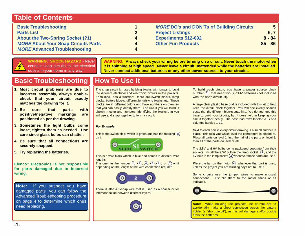
How To Use ItThe snap circuit kit uses building blocks with snaps to buildthe different electrical and electronic circuits in the projects.Each block has a function: there are switch blocks, lampblocks, battery blocks, different length wire blocks, etc. Theseblocks are in different colors and have numbers on them sothat you can easily identify them. The circuit you will build isshown in color and numbers, identifying the blocks that youwill use and snap together to form a circuit.
For Example:
This is the switch block which is green and has the marking on it.
This is a wire block which is blue and comes in different wirelengths.This one has the number , , , , , or on itdepending on the length of the wire connection required.
There is also a 1-snap wire that is used as a spacer or forinterconnection between different layers.
To build each circuit, you have a power source blocknumber that need two (2) “AA” batteries (not includedwith the snap circuit kit).
A large clear plastic base grid is included with this kit to helpkeep the circuit block together. You will see evenly spacedposts that the different blocks snap into. You do not need thisbase to build your circuits, but it does help in keeping yourcircuit together neatly. The base has rows labeled A-G andcolumns labeled 1-10.
Next to each part in every circuit drawing is a small number inblack. This tells you which level the component is placed at.Place all parts on level 1 first, then all of the parts on level 2,then all of the parts on level 3, etc.
The 2.5V and 6V bulbs come packaged separate from theirsockets. Install the 2.5V bulb in the lamp socket , and the6V bulb in the lamp socket whenever those parts are used.
Place the fan on the motor whenever that part is used,unless the project you are building says not to use it.
Some circuits use the jumper wires to make unusualconnections. Just clip them to the metal snaps or asindicated.
Note: While building the projects, be careful not toaccidentally make a direct connection across the batteryholder (a “short circuit”), as this will damage and/or quicklydrain the batteries.
B1
L1
M12 3 4 5 6
S1
7
L2
WARNING: SHOCK HAZARD - Neverconnect snap circuits to the electricaloutlets in your home in any way!
WARNING: Always check your wiring before turning on a circuit. Never touch the motor whenit is spinning at high speed. Never leave a circuit unattended while the batteries are installed.Never connect additional batteries or any other power sources to your circuits.
-2-
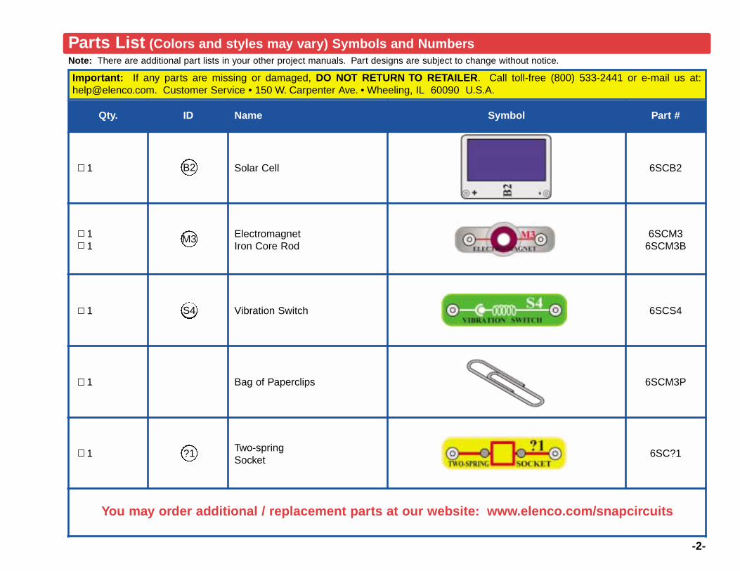
Note: There are additional part lists in your other project manuals. Part designs are subject to change without notice.
Important: If any parts are missing or damaged, DO NOT RETURN TO RETAILER. Call toll-free (800) 533-2441 or e-mail us at:[email protected]. Customer Service • 150 W. Carpenter Ave. • Wheeling, IL 60090 U.S.A.
Parts List (Colors and styles may vary) Symbols and Numbers
Qty. ID Name Symbol Part #
1 Solar Cell 6SCB2
11
ElectromagnetIron Core Rod
6SCM36SCM3B
1 Vibration Switch 6SCS4
1 Bag of Paperclips 6SCM3P
1 Two-springSocket
6SC?1
You may order additional / replacement parts at our website: www.elenco.com/snapcircuits
?1
S4
M3
B2

-3-
The two-spring socket (?1) just has two springs, and won’t doanything by itself. It is not used in any of the experiments. It wasincluded to make it easy to connect other electronic components toyour Snap Circuits. It should only be used by advanced users whoare creating their own circuits.
There are many different types of electronic components and basicparts like resistors and capacitors have a wide range of availablevalues. For example, Snap Circuits includes five fixed-valueresistors (100Ω, 1KΩ, 5.1KΩ, 10KΩ, and 100KΩ). This is a verylimited choice of values, and difficult to design circuits with. SnapCircuits also includes a variable resistor (RV), but it is difficult to setthis part to a particular value. You can place your resistors in seriesand parallel to make different values (as is done with the 5.1KΩand 10KΩ in project 166), but this is also difficult with only fivevalues to choose from.
Many customers like to create their own circuits and asked us toinclude more resistor values with Snap Circuits. We could havedone that, but you would never have enough. And resistors are notvery exciting components by themselves. You could try to use yourown resistors, but they are difficult to connect since normalelectronic parts don’t come with wires on them instead of snaps.
The two-spring socket (?1) makes it easy to connect your ownresistors (and other parts) to circuits by connecting them betweenthe springs:
Any component with two wires coming from it (called leads) can beconnected with the two-spring socket (?1), assuming the leads arelong enough. Usually you will connect different values of resistorsor capacitors, but other components like LEDs, diodes, orcoils/inductors can also be used. You can usually find electroniccomponents at any store specializing in electronics.
You can design your own circuits or substitute new parts into theprojects in the manuals. For LEDs, diodes, or electrolyticcapacitors, be sure to connect your parts using the correct polarityor you may damage them. Never exceed the voltage ratings of anyparts. ELENCOTM ELECTRONICS IS NOT RESPONSIBLE FORANY PARTS DAMAGED BY IMPROPER CIRCUIT DESIGN ORWIRING. The two-spring socket is only intended for advancedusers.
About the TWO-SPRING SOCKET (?1)
Resistor Capacitor

ElencoTM Electronics is not responsible for parts damaged due to incorrect wiring.
If you suspect you have damaged parts, you can follow this procedure to systematicallydetermine which ones need replacing:
1 - 28. Refer to the other project manuals for testing steps 1-28, then continue below.
29. Solar Cell (B2): Connect the solar cell tothe meter (M2) using snap jumpers and holdit near a lamp. The meter pointer shouldmove.
30. Electromagnet (M3): Build the mini-circuitshown here. Lamp (L1) must be dim, and mustget brighter when you press the switch (S2).
31. Vibration Switch (S4): Build the mini-circuitshown here and shake the base grid. The LEDshould go on and off as you shake.
-4-
The solar cell (B2) contains positively and negativelycharged silicon crystals, arranged in layers that canceleach other out. When sunlight shines on it, chargedparticles in the light unbalance the silicon layers andproduce an electrical voltage (about 3V). The maximumcurrent depends on how the type of light and itsbrightness, but will be much less than a battery cansupply. Bright sunlight works best, but incandescent lightbulbs also work.
The electromagnet (M3) is a large coil of wire, which actslike a magnet when a current flows through it. Placing aniron bar inside increases the magnetic effects.
When shaken, the vibraton switch (S4) contains twoseparate contacts; and a spring is connected to one ofthem. A vibration causes the spring to move, brieflyconnecting the two contacts.
The two-spring socket (?1) is described on page 3.
MORE Advanced Troubleshooting (Adult supervision recommended)MORE About YourSnap Circuits Parts
(Note: There is additional information in your other project manuals).
A Note on Sun Power
The sun produces heat and light on an immense scale,by transforming Hydrogen gas into Helium gas. This“transformation” is a thermonuclear reaction, similar tothe explosion of a Hydrogen bomb. The earth isprotected from most of this heat and radiation by beingso far away, and by its atmosphere. But even here thesun still has power, since it can spin the motor on yourkit and give you sunburn on a hot day.
Nearly all of the energy in any form on the surface of theearth originally came from the sun. Plants get energyfor growth from the sun using a process calledphotosynthesis. People and animals get energy forgrowth by eating plants (and other animals). Fossil fuelssuch as oil and coal that power most of our society arethe decayed remains of plants from long ago. Thesefuels exist in large but limited quantity, and are rapidlybeing consumed. Solar cells will produce electricity aslong as the sun is bright, and will have an ever-increasing effect on our lives.
-5-
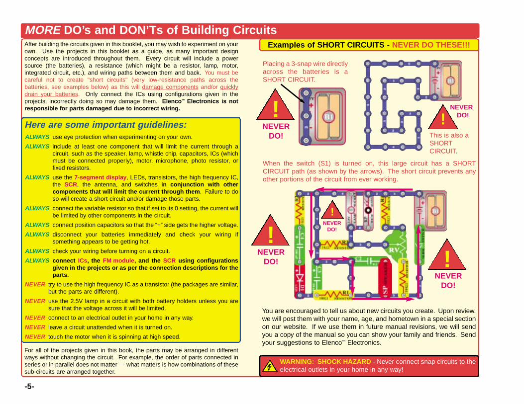
MORE DO’s and DON’Ts of Building CircuitsAfter building the circuits given in this booklet, you may wish to experiment on yourown. Use the projects in this booklet as a guide, as many important designconcepts are introduced throughout them. Every circuit will include a powersource (the batteries), a resistance (which might be a resistor, lamp, motor,integrated circuit, etc.), and wiring paths between them and back. You must becareful not to create "short circuits" (very low-resistance paths across thebatteries, see examples below) as this will damage components and/or quicklydrain your batteries. Only connect the ICs using configurations given in theprojects, incorrectly doing so may damage them. ElencoTM Electronics is notresponsible for parts damaged due to incorrect wiring.
Here are some important guidelines:ALWAYS use eye protection when experimenting on your own.
ALWAYS include at least one component that will limit the current through acircuit, such as the speaker, lamp, whistle chip, capacitors, ICs (whichmust be connected properly), motor, microphone, photo resistor, orfixed resistors.
ALWAYS use the 7-segment display, LEDs, transistors, the high frequency IC,the SCR, the antenna, and switches in conjunction with othercomponents that will limit the current through them. Failure to doso will create a short circuit and/or damage those parts.
ALWAYS connect the variable resistor so that if set to its 0 setting, the current willbe limited by other components in the circuit.
ALWAYS connect position capacitors so that the “+” side gets the higher voltage.
ALWAYS disconnect your batteries immediately and check your wiring ifsomething appears to be getting hot.
ALWAYS check your wiring before turning on a circuit.
ALWAYS connect ICs, the FM module, and the SCR using configurationsgiven in the projects or as per the connection descriptions for theparts.
NEVER try to use the high frequency IC as a transistor (the packages are similar,but the parts are different).
NEVER use the 2.5V lamp in a circuit with both battery holders unless you aresure that the voltage across it will be limited.
NEVER connect to an electrical outlet in your home in any way.
NEVER leave a circuit unattended when it is turned on.
NEVER touch the motor when it is spinning at high speed.
For all of the projects given in this book, the parts may be arranged in differentways without changing the circuit. For example, the order of parts connected inseries or in parallel does not matter — what matters is how combinations of thesesub-circuits are arranged together.
Examples of SHORT CIRCUITS - NEVER DO THESE!!!
You are encouraged to tell us about new circuits you create. Upon review,we will post them with your name, age, and hometown in a special sectionon our website. If we use them in future manual revisions, we will sendyou a copy of the manual so you can show your family and friends. Sendyour suggestions to ElencoTM Electronics.
WARNING: SHOCK HAZARD - Never connect snap circuits to theelectrical outlets in your home in any way!
Placing a 3-snap wire directlyacross the batteries is aSHORT CIRCUIT.
This is also aSHORTCIRCUIT.
When the switch (S1) is turned on, this large circuit has a SHORTCIRCUIT path (as shown by the arrows). The short circuit prevents anyother portions of the circuit from ever working.
!
!!
!
NEVERDO!
NEVERDO!
NEVERDO!
NEVERDO!
NEVERDO!!
Project # Description Page #
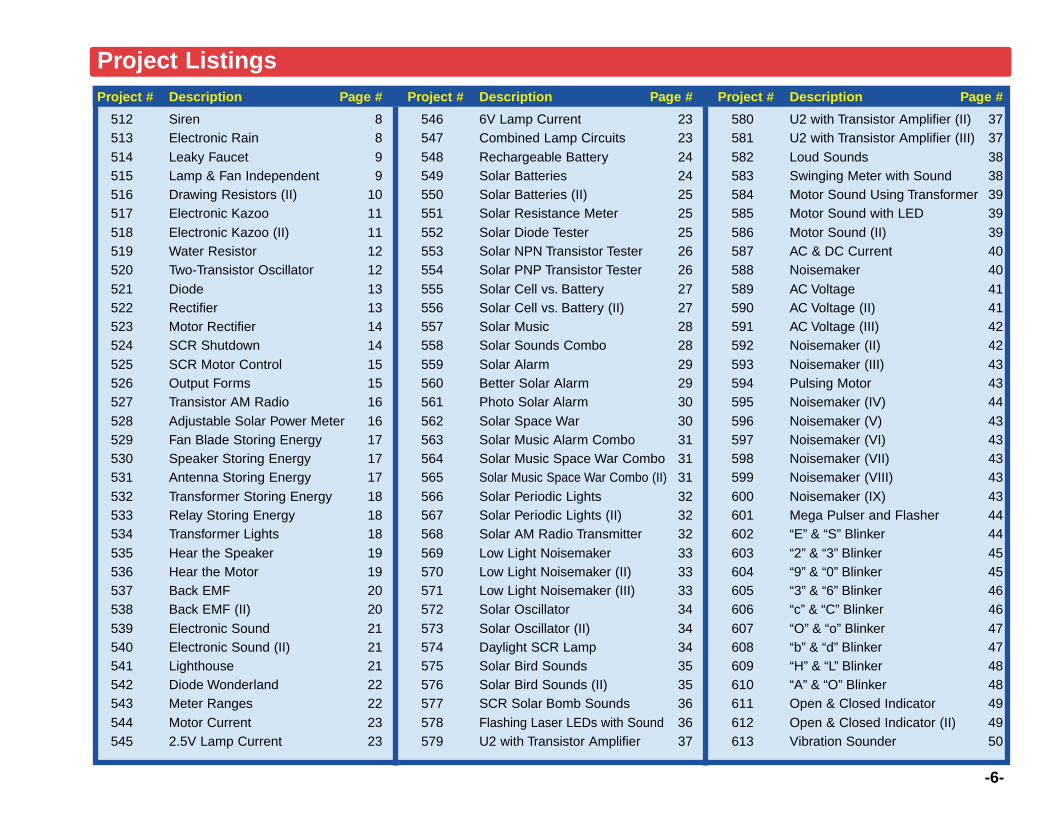
512 Siren 8513 Electronic Rain 8514 Leaky Faucet 9515 Lamp & Fan Independent 9516 Drawing Resistors (II) 10517 Electronic Kazoo 11518 Electronic Kazoo (II) 11519 Water Resistor 12520 Two-Transistor Oscillator 12521 Diode 13522 Rectifier 13523 Motor Rectifier 14524 SCR Shutdown 14525 SCR Motor Control 15526 Output Forms 15527 Transistor AM Radio 16528 Adjustable Solar Power Meter 16529 Fan Blade Storing Energy 17530 Speaker Storing Energy 17531 Antenna Storing Energy 17532 Transformer Storing Energy 18533 Relay Storing Energy 18534 Transformer Lights 18535 Hear the Speaker 19536 Hear the Motor 19537 Back EMF 20538 Back EMF (II) 20539 Electronic Sound 21540 Electronic Sound (II) 21541 Lighthouse 21542 Diode Wonderland 22543 Meter Ranges 22544 Motor Current 23545 2.5V Lamp Current 23
Project # Description Page #
546 6V Lamp Current 23547 Combined Lamp Circuits 23548 Rechargeable Battery 24549 Solar Batteries 24550 Solar Batteries (II) 25551 Solar Resistance Meter 25552 Solar Diode Tester 25553 Solar NPN Transistor Tester 26554 Solar PNP Transistor Tester 26555 Solar Cell vs. Battery 27556 Solar Cell vs. Battery (II) 27557 Solar Music 28558 Solar Sounds Combo 28559 Solar Alarm 29560 Better Solar Alarm 29561 Photo Solar Alarm 30562 Solar Space War 30563 Solar Music Alarm Combo 31564 Solar Music Space War Combo 31565 Solar Music Space War Combo (II) 31566 Solar Periodic Lights 32567 Solar Periodic Lights (II) 32568 Solar AM Radio Transmitter 32569 Low Light Noisemaker 33570 Low Light Noisemaker (II) 33571 Low Light Noisemaker (III) 33572 Solar Oscillator 34573 Solar Oscillator (II) 34574 Daylight SCR Lamp 34575 Solar Bird Sounds 35576 Solar Bird Sounds (II) 35577 SCR Solar Bomb Sounds 36578 Flashing Laser LEDs with Sound 36579 U2 with Transistor Amplifier 37
Project # Description Page #
580 U2 with Transistor Amplifier (II) 37581 U2 with Transistor Amplifier (III) 37582 Loud Sounds 38583 Swinging Meter with Sound 38584 Motor Sound Using Transformer 39585 Motor Sound with LED 39586 Motor Sound (II) 39587 AC & DC Current 40588 Noisemaker 40589 AC Voltage 41590 AC Voltage (II) 41591 AC Voltage (III) 42592 Noisemaker (II) 42593 Noisemaker (III) 43594 Pulsing Motor 43595 Noisemaker (IV) 44596 Noisemaker (V) 43597 Noisemaker (VI) 43598 Noisemaker (VII) 43599 Noisemaker (VIII) 43600 Noisemaker (IX) 43601 Mega Pulser and Flasher 44602 “E” & “S” Blinker 44603 “2” & “3” Blinker 45604 “9” & “0” Blinker 45605 “3” & “6” Blinker 46606 “c” & “C” Blinker 46607 “O” & “o” Blinker 47608 “b” & “d” Blinker 47609 “H” & “L” Blinker 48610 “A” & “O” Blinker 48611 Open & Closed Indicator 49612 Open & Closed Indicator (II) 49613 Vibration Sounder 50
-6-
Project Listings
-7-
Project # Description Page #
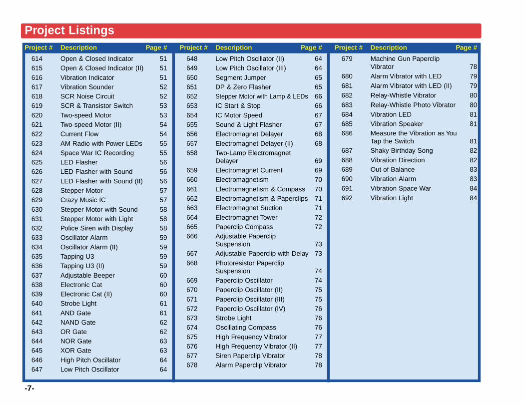
614 Open & Closed Indicator 51615 Open & Closed Indicator (II) 51616 Vibration Indicator 51617 Vibration Sounder 52618 SCR Noise Circuit 52619 SCR & Transistor Switch 53620 Two-speed Motor 53621 Two-speed Motor (II) 54622 Current Flow 54623 AM Radio with Power LEDs 55624 Space War IC Recording 55625 LED Flasher 56626 LED Flasher with Sound 56627 LED Flasher with Sound (II) 56628 Stepper Motor 57629 Crazy Music IC 57630 Stepper Motor with Sound 58631 Stepper Motor with Light 58632 Police Siren with Display 58633 Oscillator Alarm 59634 Oscillator Alarm (II) 59635 Tapping U3 59636 Tapping U3 (II) 59637 Adjustable Beeper 60638 Electronic Cat 60639 Electronic Cat (II) 60640 Strobe Light 61641 AND Gate 61642 NAND Gate 62643 OR Gate 62644 NOR Gate 63645 XOR Gate 63646 High Pitch Oscillator 64647 Low Pitch Oscillator 64
Project # Description Page #
648 Low Pitch Oscillator (II) 64649 Low Pitch Oscillator (III) 64650 Segment Jumper 65651 DP & Zero Flasher 65652 Stepper Motor with Lamp & LEDs 66653 IC Start & Stop 66654 IC Motor Speed 67655 Sound & Light Flasher 67656 Electromagnet Delayer 68657 Electromagnet Delayer (II) 68658 Two-Lamp Electromagnet
Delayer 69659 Electromagnet Current 69660 Electromagnetism 70661 Electromagnetism & Compass 70662 Electromagnetism & Paperclips 71663 Electromagnet Suction 71664 Electromagnet Tower 72665 Paperclip Compass 72666 Adjustable Paperclip
Suspension 73667 Adjustable Paperclip with Delay 73668 Photoresistor Paperclip
Suspension 74669 Paperclip Oscillator 74670 Paperclip Oscillator (II) 75671 Paperclip Oscillator (III) 75672 Paperclip Oscillator (IV) 76673 Strobe Light 76674 Oscillating Compass 76675 High Frequency Vibrator 77676 High Frequency Vibrator (II) 77677 Siren Paperclip Vibrator 78678 Alarm Paperclip Vibrator 78
Project # Description Page #
679 Machine Gun PaperclipVibrator 78
680 Alarm Vibrator with LED 79681 Alarm Vibrator with LED (II) 79682 Relay-Whistle Vibrator 80683 Relay-Whistle Photo Vibrator 80684 Vibration LED 81685 Vibration Speaker 81686 Measure the Vibration as You
Tap the Switch 81687 Shaky Birthday Song 82688 Vibration Direction 82689 Out of Balance 83690 Vibration Alarm 83691 Vibration Space War 84692 Vibration Light 84
Project Listings
-8-
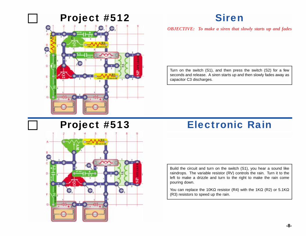
Project #512OBJECTIVE: To make a siren that slowly starts up and fades
Turn on the switch (S1), and then press the switch (S2) for a fewseconds and release. A siren starts up and then slowly fades away ascapacitor C3 discharges.
Siren
Project #513
Build the circuit and turn on the switch (S1), you hear a sound likeraindrops. The variable resistor (RV) controls the rain. Turn it to theleft to make a drizzle and turn to the right to make the rain comepouring down.
You can replace the 10KΩ resistor (R4) with the 1KΩ (R2) or 5.1KΩ(R3) resistors to speed up the rain.
Electronic Rain
-9-
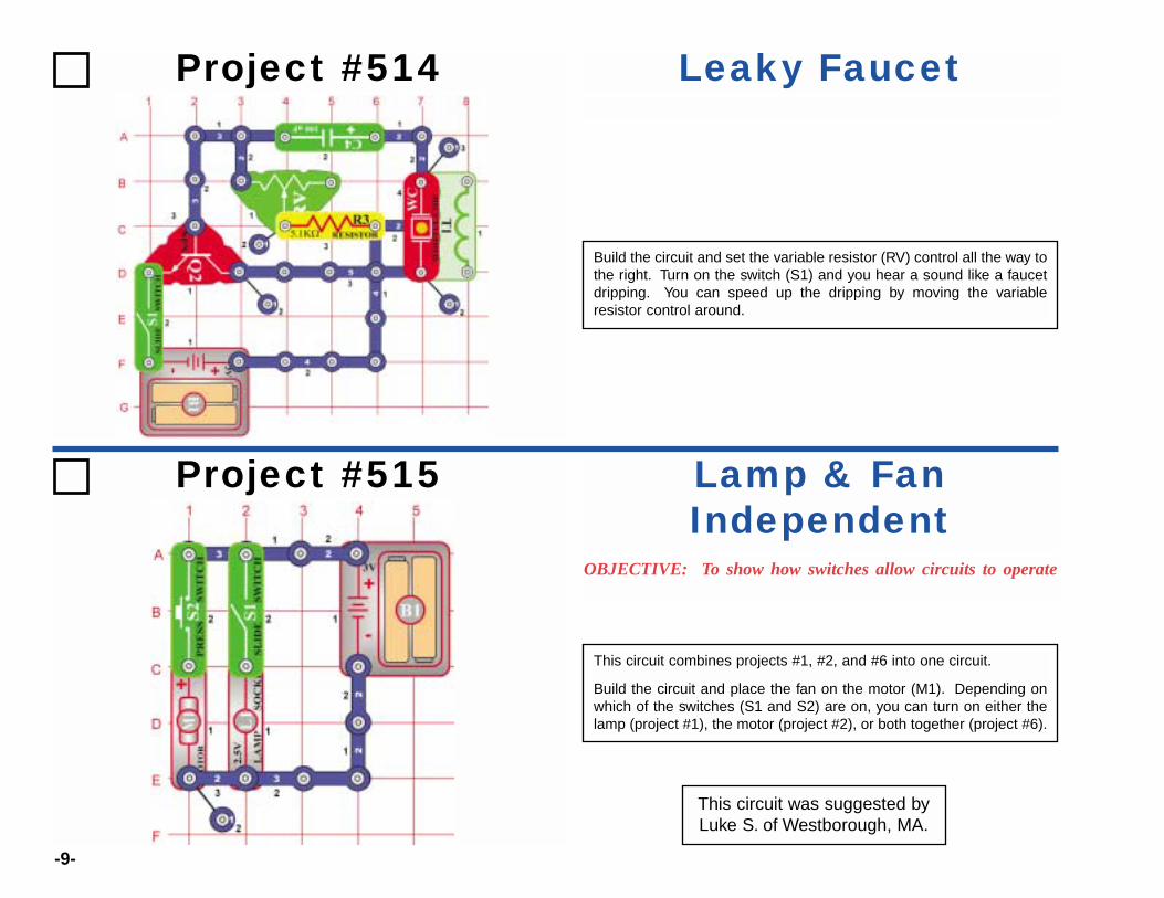
This circuit was suggested byLuke S. of Westborough, MA.
Project #514
Build the circuit and set the variable resistor (RV) control all the way tothe right. Turn on the switch (S1) and you hear a sound like a faucetdripping. You can speed up the dripping by moving the variableresistor control around.
Leaky Faucet
Project #515
OBJECTIVE: To show how switches allow circuits to operate
This circuit combines projects #1, #2, and #6 into one circuit.
Build the circuit and place the fan on the motor (M1). Depending onwhich of the switches (S1 and S2) are on, you can turn on either thelamp (project #1), the motor (project #2), or both together (project #6).
Lamp & FanIndependent

-10-
You need some more parts to do this experiment, so you’re going todraw them. Take a pencil (No. 2 lead is best but other types will alsowork), SHARPEN IT, and fill in the 4 rectangles you see below. Youwill get better results if you place a hard, flat surface between thispage and the rest of this booklet while you are drawing. Press hard(but don’t rip the paper) and fill in each several times to be sure youhave a thick, even layer of pencil lead and try to avoid going out ofthe boundaries.
Actually, your pencils aren’t made out of lead anymore (although westill call them “lead pencils”). The “lead” in your pencils is really a formof carbon, the same material that resistors are made of. So thedrawings you just made should act just like the resistors in SnapCircuits.
Build the circuit shown, it is the same basic oscillator circuit you havebeen using. Touch the the loose ends of the jumper wires to oppositeends of the rectangles you drew, you should hear a sound like analarm. Note: You may get better electrical contact between the wiresand the drawings if you wet the metal with a few drops of water orsaliva.
Making the drawn resistors longer should increase the resistancewhile making them wider should reduce the resistance. So all 4rectangles should produce the same sound, though you will seevariations due to how thick and evenly you filled in the rectangles, andexactly where you touch the wires. If your 4 shapes don’t soundsimilar then try improving your drawings.
Be sure to wash your hands after this project.
Shapes to be drawn.
Use a SHARP No. 2 pencil, draw ona hard surface, press hard and fill in
several times for best results.
Project #516 Drawing Resistors (II)
-11-
Shape to be drawn.
Use a SHARP No. 2 pencil, draw ona hard surface, press hard and fill in
several times for best results.
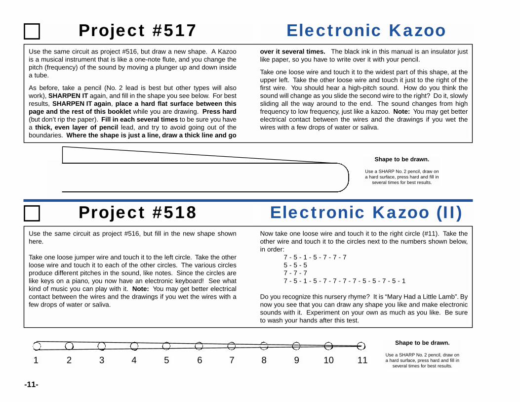
Use the same circuit as project #516, but draw a new shape. A Kazoois a musical instrument that is like a one-note flute, and you change thepitch (frequency) of the sound by moving a plunger up and down insidea tube.
As before, take a pencil (No. 2 lead is best but other types will alsowork), SHARPEN IT again, and fill in the shape you see below. For bestresults, SHARPEN IT again, place a hard flat surface between thispage and the rest of this booklet while you are drawing. Press hard(but don’t rip the paper). Fill in each several times to be sure you havea thick, even layer of pencil lead, and try to avoid going out of theboundaries. Where the shape is just a line, draw a thick line and go
over it several times. The black ink in this manual is an insulator justlike paper, so you have to write over it with your pencil.
Take one loose wire and touch it to the widest part of this shape, at theupper left. Take the other loose wire and touch it just to the right of thefirst wire. You should hear a high-pitch sound. How do you think thesound will change as you slide the second wire to the right? Do it, slowlysliding all the way around to the end. The sound changes from highfrequency to low frequency, just like a kazoo. Note: You may get betterelectrical contact between the wires and the drawings if you wet thewires with a few drops of water or saliva.
Shape to be drawn.
Use a SHARP No. 2 pencil, draw ona hard surface, press hard and fill in
several times for best results.1 2 3 4 5 6 7 8 9 10 11
Project #517 Electronic Kazoo
Project #518 Electronic Kazoo (II)Use the same circuit as project #516, but fill in the new shape shownhere.
Take one loose jumper wire and touch it to the left circle. Take the otherloose wire and touch it to each of the other circles. The various circlesproduce different pitches in the sound, like notes. Since the circles arelike keys on a piano, you now have an electronic keyboard! See whatkind of music you can play with it. Note: You may get better electricalcontact between the wires and the drawings if you wet the wires with afew drops of water or saliva.
Now take one loose wire and touch it to the right circle (#11). Take theother wire and touch it to the circles next to the numbers shown below,in order:
7 - 5 - 1 - 5 - 7 - 7 - 75 - 5 - 57 - 7 - 77 - 5 - 1 - 5 - 7 - 7 - 7 - 7 - 5 - 5 - 7 - 5 - 1
Do you recognize this nursery rhyme? It is “Mary Had a Little Lamb”. Bynow you see that you can draw any shape you like and make electronicsounds with it. Experiment on your own as much as you like. Be sureto wash your hands after this test.
-12-
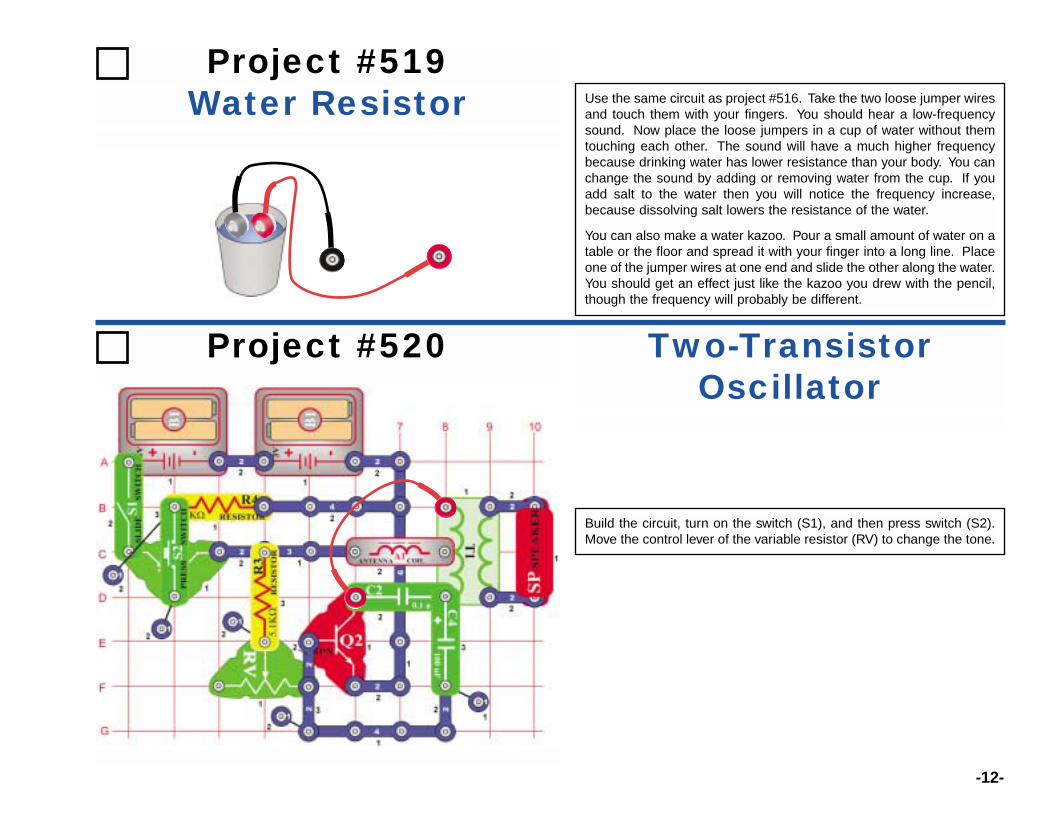
Use the same circuit as project #516. Take the two loose jumper wiresand touch them with your fingers. You should hear a low-frequencysound. Now place the loose jumpers in a cup of water without themtouching each other. The sound will have a much higher frequencybecause drinking water has lower resistance than your body. You canchange the sound by adding or removing water from the cup. If youadd salt to the water then you will notice the frequency increase,because dissolving salt lowers the resistance of the water.
You can also make a water kazoo. Pour a small amount of water on atable or the floor and spread it with your finger into a long line. Placeone of the jumper wires at one end and slide the other along the water.You should get an effect just like the kazoo you drew with the pencil,though the frequency will probably be different.
Project #519Water Resistor
Project #520
Build the circuit, turn on the switch (S1), and then press switch (S2).Move the control lever of the variable resistor (RV) to change the tone.
Two-TransistorOscillator
-13-
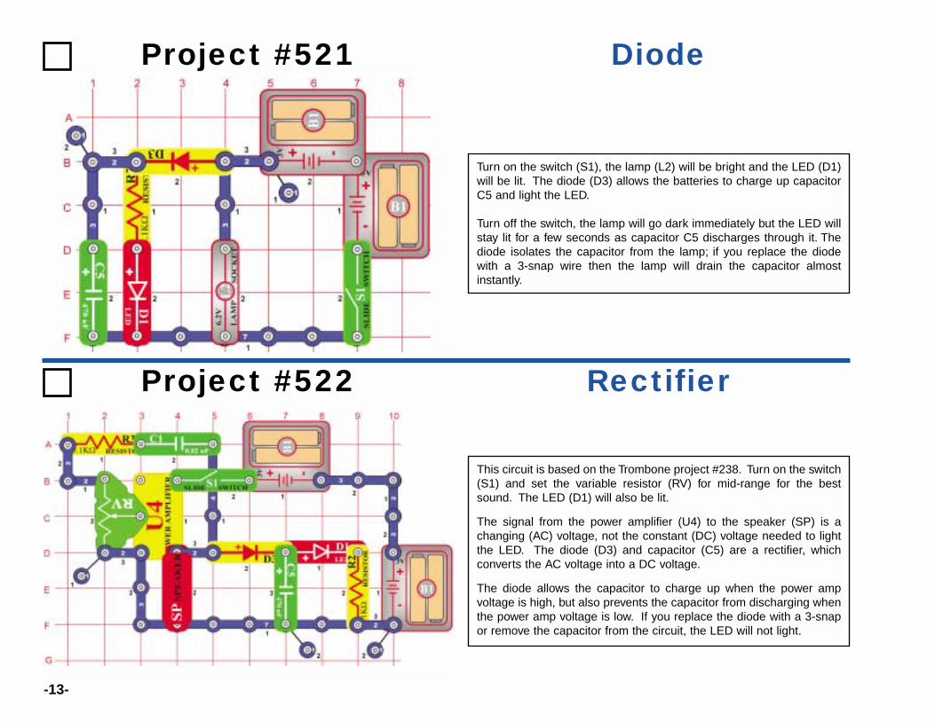
Turn on the switch (S1), the lamp (L2) will be bright and the LED (D1)will be lit. The diode (D3) allows the batteries to charge up capacitorC5 and light the LED.
Turn off the switch, the lamp will go dark immediately but the LED willstay lit for a few seconds as capacitor C5 discharges through it. Thediode isolates the capacitor from the lamp; if you replace the diodewith a 3-snap wire then the lamp will drain the capacitor almostinstantly.
Project #521 Diode
Project #522 Rectifier
This circuit is based on the Trombone project #238. Turn on the switch(S1) and set the variable resistor (RV) for mid-range for the bestsound. The LED (D1) will also be lit.
The signal from the power amplifier (U4) to the speaker (SP) is achanging (AC) voltage, not the constant (DC) voltage needed to lightthe LED. The diode (D3) and capacitor (C5) are a rectifier, whichconverts the AC voltage into a DC voltage.
The diode allows the capacitor to charge up when the power ampvoltage is high, but also prevents the capacitor from discharging whenthe power amp voltage is low. If you replace the diode with a 3-snapor remove the capacitor from the circuit, the LED will not light.

-14-
Set the meter (M2) to the 10MA scale. Place the fan on the motor (M1)and turn on the switch (S1), the meter measures the current on theother side of the transformer (T1).
As the DC voltage from the battery (B1) spins the motor, the motorcreates an AC ripple in the voltage. This ripple passes through thetransformer using magnetism. The diode and 0.1µF capacitor (C2)“rectify” the AC ripple into the DC current that the meter measures.
Holding down the press switch (S2) connects the 470µF capacitor(C5) across the motor. This filters out the AC ripple, so the currentthrough the meter is greatly reduced but the motor speed is notaffected.
Project #523 Motor Rectifier
Project #524 SCR Shutdown
In this circuit the press switch (S2) controls an SCR (Q3), whichcontrols a transistor (Q2), which controls an LED (D1). Set thevariable resistor (RV) control lever to the top (toward the press switch).
Turn on the slide switch (S1); nothing happens. Press and release thepress switch; the SCR, transistor, and LED turn on and stay on. Nowmove the variable resistor control down until the LED turns off. Pressand release the press switch again, this time the LED comes on butgoes off after you release the switch.
If the current through an SCR (anode-to-cathode) is above a thresholdlevel, then the SCR stays on. In this circuit you can set the variableresistor so that the SCR (and the LED it controls) just barely stays onor shuts off.
-15-
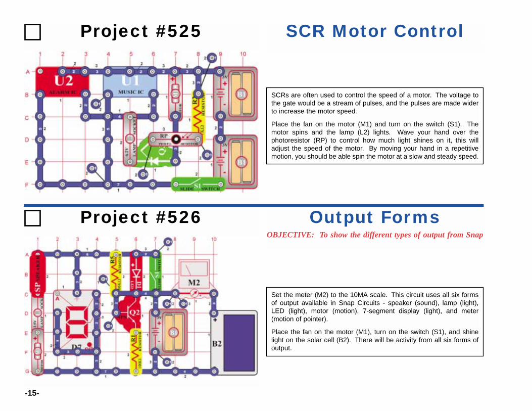
SCRs are often used to control the speed of a motor. The voltage tothe gate would be a stream of pulses, and the pulses are made widerto increase the motor speed.
Place the fan on the motor (M1) and turn on the switch (S1). Themotor spins and the lamp (L2) lights. Wave your hand over thephotoresistor (RP) to control how much light shines on it, this willadjust the speed of the motor. By moving your hand in a repetitivemotion, you should be able spin the motor at a slow and steady speed.
Project #525 SCR Motor Control
Project #526OBJECTIVE: To show the different types of output from Snap
Output Forms
Set the meter (M2) to the 10MA scale. This circuit uses all six formsof output available in Snap Circuits - speaker (sound), lamp (light),LED (light), motor (motion), 7-segment display (light), and meter(motion of pointer).
Place the fan on the motor (M1), turn on the switch (S1), and shinelight on the solar cell (B2). There will be activity from all six forms ofoutput.
-16-
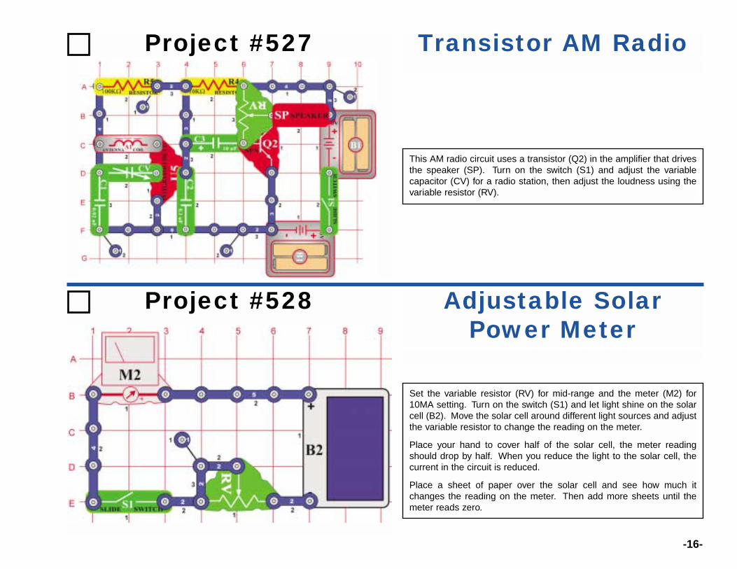
This AM radio circuit uses a transistor (Q2) in the amplifier that drivesthe speaker (SP). Turn on the switch (S1) and adjust the variablecapacitor (CV) for a radio station, then adjust the loudness using thevariable resistor (RV).
Project #527 Transistor AM Radio
Project #528 Adjustable SolarPower Meter
Set the variable resistor (RV) for mid-range and the meter (M2) for10MA setting. Turn on the switch (S1) and let light shine on the solarcell (B2). Move the solar cell around different light sources and adjustthe variable resistor to change the reading on the meter.
Place your hand to cover half of the solar cell, the meter readingshould drop by half. When you reduce the light to the solar cell, thecurrent in the circuit is reduced.
Place a sheet of paper over the solar cell and see how much itchanges the reading on the meter. Then add more sheets until themeter reads zero.
-17-
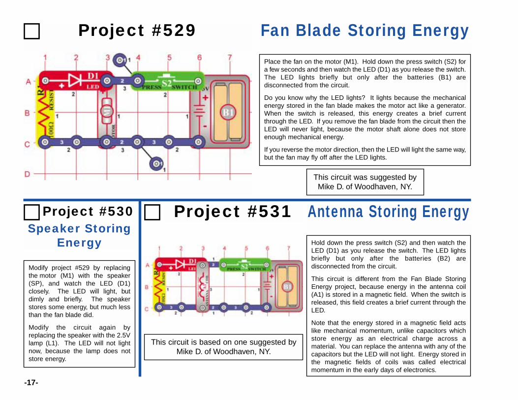
Hold down the press switch (S2) and then watch theLED (D1) as you release the switch. The LED lightsbriefly but only after the batteries (B2) aredisconnected from the circuit.
This circuit is different from the Fan Blade StoringEnergy project, because energy in the antenna coil(A1) is stored in a magnetic field. When the switch isreleased, this field creates a brief current through theLED.
Note that the energy stored in a magnetic field actslike mechanical momentum, unlike capacitors whichstore energy as an electrical charge across amaterial. You can replace the antenna with any of thecapacitors but the LED will not light. Energy stored inthe magnetic fields of coils was called electricalmomentum in the early days of electronics.
Modify project #529 by replacingthe motor (M1) with the speaker(SP), and watch the LED (D1)closely. The LED will light, butdimly and briefly. The speakerstores some energy, but much lessthan the fan blade did.
Modify the circuit again byreplacing the speaker with the 2.5Vlamp (L1). The LED will not lightnow, because the lamp does notstore energy.
Speaker StoringEnergy
Project #529 Fan Blade Storing Energy
Project #531 Antenna Storing Energy
Place the fan on the motor (M1). Hold down the press switch (S2) fora few seconds and then watch the LED (D1) as you release the switch.The LED lights briefly but only after the batteries (B1) aredisconnected from the circuit.
Do you know why the LED lights? It lights because the mechanicalenergy stored in the fan blade makes the motor act like a generator.When the switch is released, this energy creates a brief currentthrough the LED. If you remove the fan blade from the circuit then theLED will never light, because the motor shaft alone does not storeenough mechanical energy.
If you reverse the motor direction, then the LED will light the same way,but the fan may fly off after the LED lights.
This circuit was suggested byMike D. of Woodhaven, NY.
This circuit is based on one suggested byMike D. of Woodhaven, NY.
Project #530
-18-
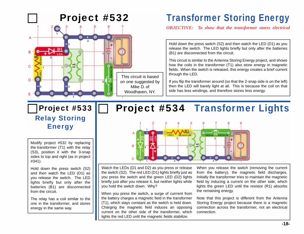
Watch the LEDs (D1 and D2) as you press or releasethe switch (S2). The red LED (D1) lights briefly just asyou press the switch and the green LED (D2) lightsbriefly just after you release it, but neither lights whileyou hold the switch down. Why?
When you press the switch, a surge of currrent fromthe battery charges a magnetic field in the transformer(T1), which stays constant as the switch is held down.Charging the magnetic field induces an opposingcurrent on the other side of the transformer, whichlights the red LED until the magnetic fields stabilize.
When you release the switch (removing the currentfrom the battery), the magnetic field discharges.Initially the transformer tries to maintain the magneticfield by inducing a current on the other side, whichlights the green LED until the resistor (R1) absorbsthe remaining energy.
Note that this project is different from the AntennaStoring Energy project because there is a magneticconnection across the transformer, not an electricalconnection.
Modify project #532 by replacingthe transformer (T1) with the relay(S3), position it with the 3-snapsides to top and right (as in project#341).
Hold down the press switch (S2)and then watch the LED (D1) asyou release the switch. The LEDlights briefly but only after thebatteries (B1) are disconnectedfrom the circuit.
The relay has a coil similar to theone in the transformer, and storesenergy in the same way.
Relay StoringEnergy
Project #532OBJECTIVE: To show that the transformer stores electrical
Transformer Storing Energy
Project #534 Transformer Lights
Hold down the press switch (S2) and then watch the LED (D1) as yourelease the switch. The LED lights briefly but only after the batteries(B1) are disconnected from the circuit.
This circuit is similar to the Antenna Storing Energy project, and showshow the coils in the transformer (T1) also store energy in magneticfields. When the switch is released, this energy creates a brief currentthrough the LED.
If you flip the transformer around (so that the 2-snap side is on the left)then the LED will barely light at all. This is because the coil on thatside has less windings, and therefore stores less energy.
Project #533
This circuit is basedon one suggested by
Mike D. ofWoodhaven, NY.
-19-
Hold the speaker (SP) up to your ear and press the switch (S2) severaltimes. You hear a click each time you press or release the switch, buthear nothing while you are holding it down. Do you know why?
The speaker contains a coil of wire wrapped around a small magnet.Whenever the voltage to the speaker changes, magnetic effects fromthe coil move the magnet. This creates a change in air pressure thatyour ears feel and recognize as sound. The magnet only moves whenthe voltage changes, and the voltage only changes when you press orrelease the switch.
Project #535 Hear the Speaker
Project #536 Hear the Motor
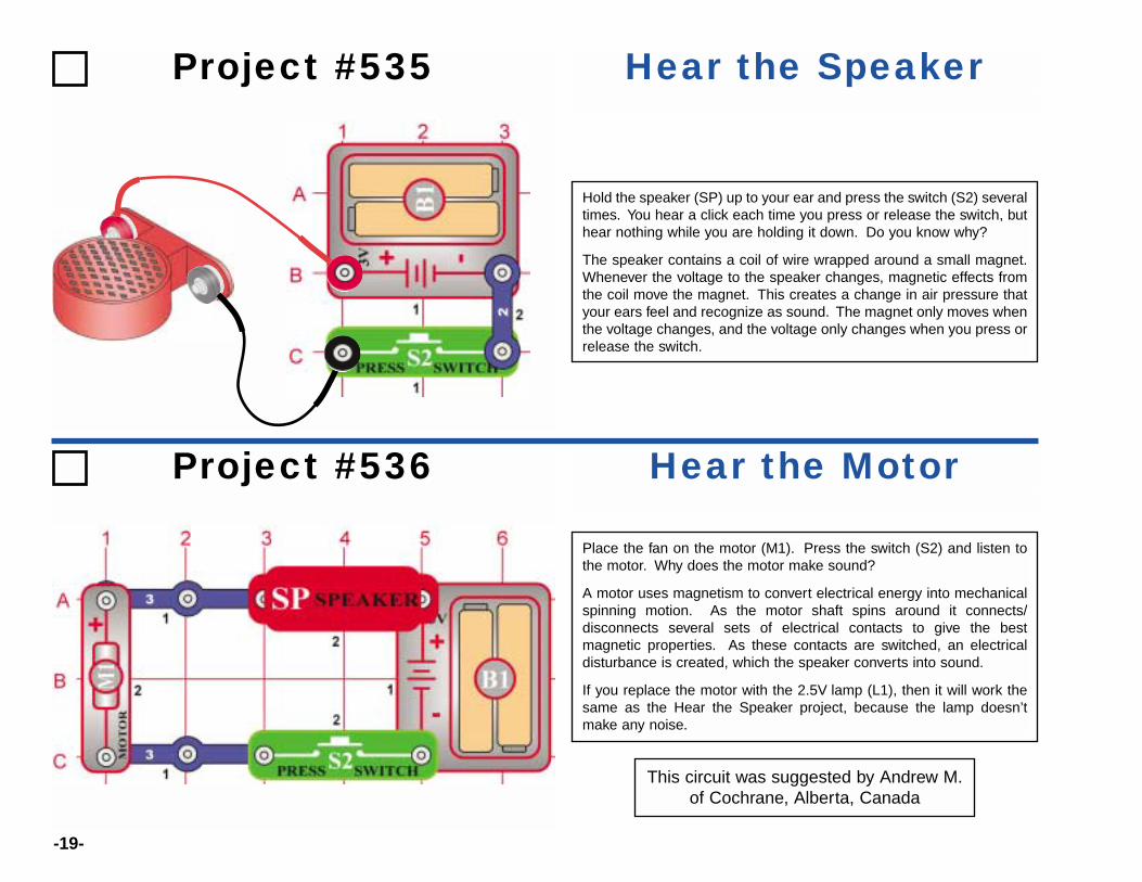
Place the fan on the motor (M1). Press the switch (S2) and listen tothe motor. Why does the motor make sound?
A motor uses magnetism to convert electrical energy into mechanicalspinning motion. As the motor shaft spins around it connects/disconnects several sets of electrical contacts to give the bestmagnetic properties. As these contacts are switched, an electricaldisturbance is created, which the speaker converts into sound.
If you replace the motor with the 2.5V lamp (L1), then it will work thesame as the Hear the Speaker project, because the lamp doesn’tmake any noise.
This circuit was suggested by Andrew M.of Cochrane, Alberta, Canada
-20-
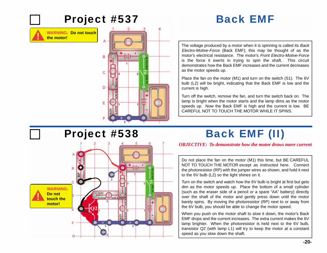
The voltage produced by a motor when it is spinning is called its BackElectro-Motive-Force (Back EMF); this may be thought of as themotor’s electrical resistance. The motor’s Front Electro-Motive-Forceis the force it exerts in trying to spin the shaft. This circuitdemonstrates how the Back EMF increases and the current decreasesas the motor speeds up.
Place the fan on the motor (M1) and turn on the switch (S1). The 6Vbulb (L2) will be bright, indicating that the Back EMF is low and thecurrent is high.
Turn off the switch, remove the fan, and turn the switch back on. Thelamp is bright when the motor starts and the lamp dims as the motorspeeds up. Now the Back EMF is high and the current is low. BECAREFUL NOT TO TOUCH THE MOTOR WHILE IT SPINS.
Project #537 Back EMF
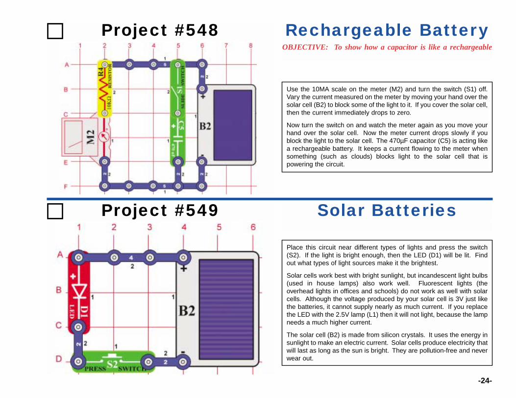
Project #538OBJECTIVE: To demonstrate how the motor draws more current
Back EMF (II)
Do not place the fan on the motor (M1) this time, but BE CAREFULNOT TO TOUCH THE MOTOR except as instructed here. Connectthe photoresistor (RP) with the jumper wires as shown, and hold it nextto the 6V bulb (L2) so the light shines on it.
Turn on the switch and watch how the 6V bulb is bright at first but getsdim as the motor speeds up. Place the bottom of a small cylinder(such as the eraser side of a pencil or a spare “AA” battery) directlyover the shaft of the motor and gently press down until the motorbarely spins. By moving the photoresistor (RP) next to or away fromthe 6V bulb, you should be able to change the motor speed.
When you push on the motor shaft to slow it down, the motor’s BackEMF drops and the current increases. The extra current makes the 6Vlamp brighter. When the photoresistor is held next to the 6V bulb,transistor Q2 (with lamp L1) will try to keep the motor at a constantspeed as you slow down the shaft.
WARNING: Do not touchthe motor!!
WARNING:Do nottouch themotor!
!

-21-
Build the circuit and turn on the slide switch (S1), you hear a high-frequency tone. Press the switch (S2) to lower the frequency byincreasing the capacitance in the oscillator. Replace the 0.1µFcapacitor (C2) with the 10µF capacitor (C3) to further lower thefrequency of the tone.
Project #539 Electronic Sound
Project #541 Lighthouse
Build the circuit and turn on the switch (S1), the LED (D1) flashesabout once a second.
You can also change the frequency by changing the resistance in theoscillator. Replace the 100KΩ resistor (R5) with the 10KΩ resistor
Electronic Sound (II)Project #540

-22-
Cover the solar cell and turn on the slide switch (S1), there should be little orno light from the LEDs (results depend on your batteries). Shine a bright lighton the solar cell (B2) and the red (D1) and green (D2) LEDs should be bright,along with one segment of the 7-segment display (D7).
This circuit shows how it takes a lot of voltage to turn on a bunch of diodesconnected in a series. Since the transistors (Q1 and Q2) are used as diodeshere, there are six diodes total (D1, D2, D3, D7, Q1, and Q2). The voltagefrom the batteries (B1) alone is not enough to turn them all on at the sametime, but the extra voltage produced by the solar cell is enough to make thembright.
Now push the press switch (S2) and D7 will display “0”, but it will be dim unlessthe light on the solar cell is very bright. With S2 off, all the current through D7goes through segment B and makes it bright. With S2 on, the current throughD7 divides evenly between several segments.
Note that this circuit appears to violate the Do’s & Don’ts of Building Circuitsrules (on page 5) because there is no component to limit the current throughthe LEDs. However the solar cell itself will limit the current.
Project #542 Diode Wonderland
Project #543OBJECTIVE: To show the difference between the low and high
Meter Ranges
Use the 10MA setting on the meter (M2), turn off the switch (S1), andunscrew the 2.5V bulb (L1). The meter should measure about 2, sincethe 100KΩ resistor (R5) keeps the current low. Results will varydepending on how good your batteries are.
Screw in the 2.5V bulb to add the 10KΩ resistor (R4) to the circuit, nowthe meter reading will be about 10.
Now turn on the switch (S1) to add the 100Ω resistor (R1) to the circuit,the meter reading should be off the scale to the right. Change themeter to the high-current 1A setting, it should read just above zero.
Now press the switch (S2) to add the speaker (SP) to the circuit. Themeter reading will be about 5, since the speaker has only about 8Ωresistance.

-23-
Use the 1A setting on the meter (M2) and place the fan on the motor (M1). Press the switch(S2), the meter will measure a very high current because it takes a lot of power to spin the fan.
Remove the fan and press the switch again. The meter reading will be lower sincespinning the motor without the fan takes less power.
Project #544 Motor Current
Project #5452.5V Lamp Current
Use the circuit from project #544, but replace the motor with the 2.5V lamp (L1). Measurethe current using the 1A setting on the meter.
Project #5466V Lamp Current
Use the circuit from project #544 but replace the motor with the 6V lamp (L2). Measurethe current using the 1A setting on the meter. Compare the lamp brightness and meterreading to that for the 2.5V lamp.
Project #547 Combined Lamp Circuits
Use the 1A setting on the meter (M2) and turn on the slide switch (S1).Both lamps are on and the meter measures the current.
Now turn on the press switch (S2) to bypass the 2.5V lamp (L1). The6V lamp (L2) is brighter now, and the meter measures a highercurrent.
-24-
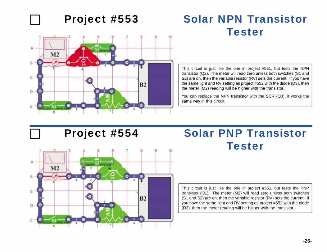
Use the 10MA scale on the meter (M2) and turn the switch (S1) off.Vary the current measured on the meter by moving your hand over thesolar cell (B2) to block some of the light to it. If you cover the solar cell,then the current immediately drops to zero.
Now turn the switch on and watch the meter again as you move yourhand over the solar cell. Now the meter current drops slowly if youblock the light to the solar cell. The 470µF capacitor (C5) is acting likea rechargeable battery. It keeps a current flowing to the meter whensomething (such as clouds) blocks light to the solar cell that ispowering the circuit.
Project #548OBJECTIVE: To show how a capacitor is like a rechargeable
Rechargeable Battery
Project #549 Solar Batteries
Place this circuit near different types of lights and press the switch(S2). If the light is bright enough, then the LED (D1) will be lit. Findout what types of light sources make it the brightest.
Solar cells work best with bright sunlight, but incandescent light bulbs(used in house lamps) also work well. Fluorescent lights (theoverhead lights in offices and schools) do not work as well with solarcells. Although the voltage produced by your solar cell is 3V just likethe batteries, it cannot supply nearly as much current. If you replacethe LED with the 2.5V lamp (L1) then it will not light, because the lampneeds a much higher current.
The solar cell (B2) is made from silicon crystals. It uses the energy insunlight to make an electric current. Solar cells produce electricity thatwill last as long as the sun is bright. They are pollution-free and neverwear out.

-25-
Place this circuit near different types of lights and press the switch(S2), if the light is bright enough then the LEDs (D1 and D2) will be lit.Find out what types of light sources make it brightest.
The LEDs will be dimmer than in project #549, since the limited currentfrom the solar cell is divided between them. The LEDs don’t need aresistor in the circuit, because the solar cell cannot supply enoughelectric current to damage them.
Project #550 Solar Batteries (II)
Place the circuit near a bright light and set the variable resistor (RV) so thatthe meter (M2) reads “10” on the 10MA setting. Now replace the 3-snapbetween points A and B with another component to test, such as a resistor,capacitor, motor, photoresistor, or lamp. The 100µF (C4) or 470µF (C5)capacitors will give a high reading that slowly drops to zero.
You can also use the two-spring socket (?1) and place your own componentsbetween its springs to test them.
Project #551 Solar Resistance Meter
Solar Diode TesterUse the same circuit to test the red and green LEDs (D1 and D2), and thediode (D3). The diode will give a higher meter reading than the LEDs, and allthree will block current in one direction.
Project #552
-26-
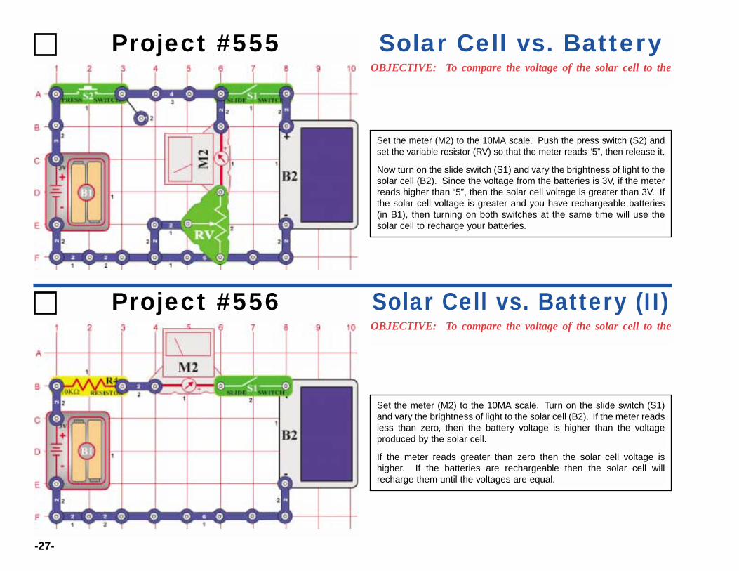
Project #553 Solar NPN TransistorTester
This circuit is just like the one in project #551, but tests the NPNtransistor (Q2). The meter will read zero unless both switches (S1 andS2) are on, then the variable resistor (RV) sets the current. If you havethe same light and RV setting as project #552 with the diode (D3), thenthe meter (M2) reading will be higher with the transistor.
You can replace the NPN transistor with the SCR (Q3), it works thesame way in this circuit.
Project #554 Solar PNP TransistorTester
This circuit is just like the one in project #551, but tests the PNPtransistor (Q1). The meter (M2) will read zero unless both switches(S1 and S2) are on, then the variable resistor (RV) sets the current. Ifyou have the same light and RV setting as project #552 with the diode(D3), then the meter reading will be higher with the transistor.
-27-
Project #555OBJECTIVE: To compare the voltage of the solar cell to the
Solar Cell vs. Battery
Set the meter (M2) to the 10MA scale. Push the press switch (S2) andset the variable resistor (RV) so that the meter reads “5”, then release it.
Now turn on the slide switch (S1) and vary the brightness of light to thesolar cell (B2). Since the voltage from the batteries is 3V, if the meterreads higher than “5”, then the solar cell voltage is greater than 3V. Ifthe solar cell voltage is greater and you have rechargeable batteries(in B1), then turning on both switches at the same time will use thesolar cell to recharge your batteries.
Project #556OBJECTIVE: To compare the voltage of the solar cell to the
Solar Cell vs. Battery (II)
Set the meter (M2) to the 10MA scale. Turn on the slide switch (S1)and vary the brightness of light to the solar cell (B2). If the meter readsless than zero, then the battery voltage is higher than the voltageproduced by the solar cell.
If the meter reads greater than zero then the solar cell voltage ishigher. If the batteries are rechargeable then the solar cell willrecharge them until the voltages are equal.
-28-
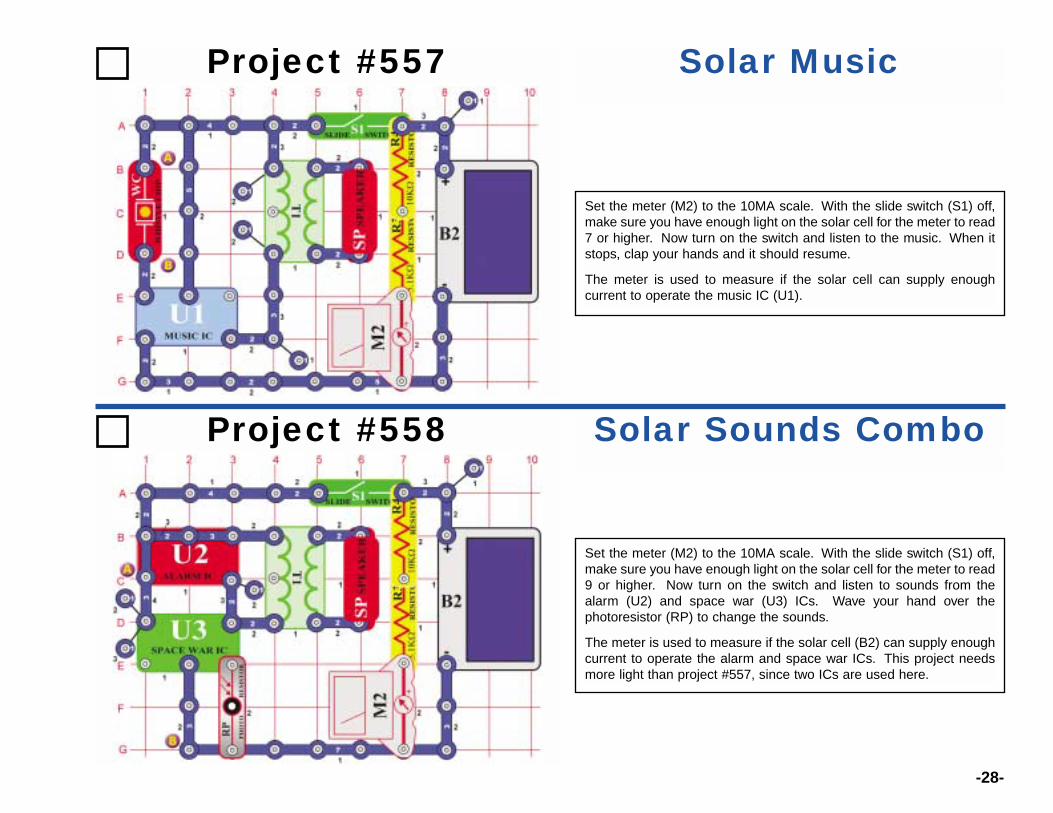
Project #557 Solar Music
Set the meter (M2) to the 10MA scale. With the slide switch (S1) off,make sure you have enough light on the solar cell for the meter to read7 or higher. Now turn on the switch and listen to the music. When itstops, clap your hands and it should resume.
The meter is used to measure if the solar cell can supply enoughcurrent to operate the music IC (U1).
Project #558 Solar Sounds Combo
Set the meter (M2) to the 10MA scale. With the slide switch (S1) off,make sure you have enough light on the solar cell for the meter to read9 or higher. Now turn on the switch and listen to sounds from thealarm (U2) and space war (U3) ICs. Wave your hand over thephotoresistor (RP) to change the sounds.
The meter is used to measure if the solar cell (B2) can supply enoughcurrent to operate the alarm and space war ICs. This project needsmore light than project #557, since two ICs are used here.
-29-
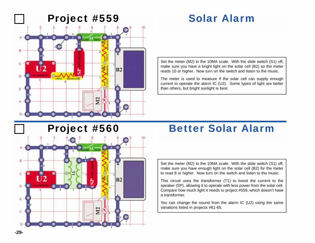
Project #559 Solar Alarm
Set the meter (M2) to the 10MA scale. With the slide switch (S1) off,make sure you have a bright light on the solar cell (B2) so the meterreads 10 or higher. Now turn on the switch and listen to the music.
The meter is used to measure if the solar cell can supply enoughcurrent to operate the alarm IC (U2). Some types of light are betterthan others, but bright sunlight is best.
Project #560 Better Solar Alarm
Set the meter (M2) to the 10MA scale. With the slide switch (S1) off,make sure you have enough light on the solar cell (B2) for the meterto read 8 or higher. Now turn on the switch and listen to the music.
This circuit uses the transformer (T1) to boost the current to thespeaker (SP), allowing it to operate with less power from the solar cell.Compare how much light it needs to project #559, which doesn’t havea transformer.
You can change the sound from the alarm IC (U2) using the samevariations listed in projects #61-65.
-30-
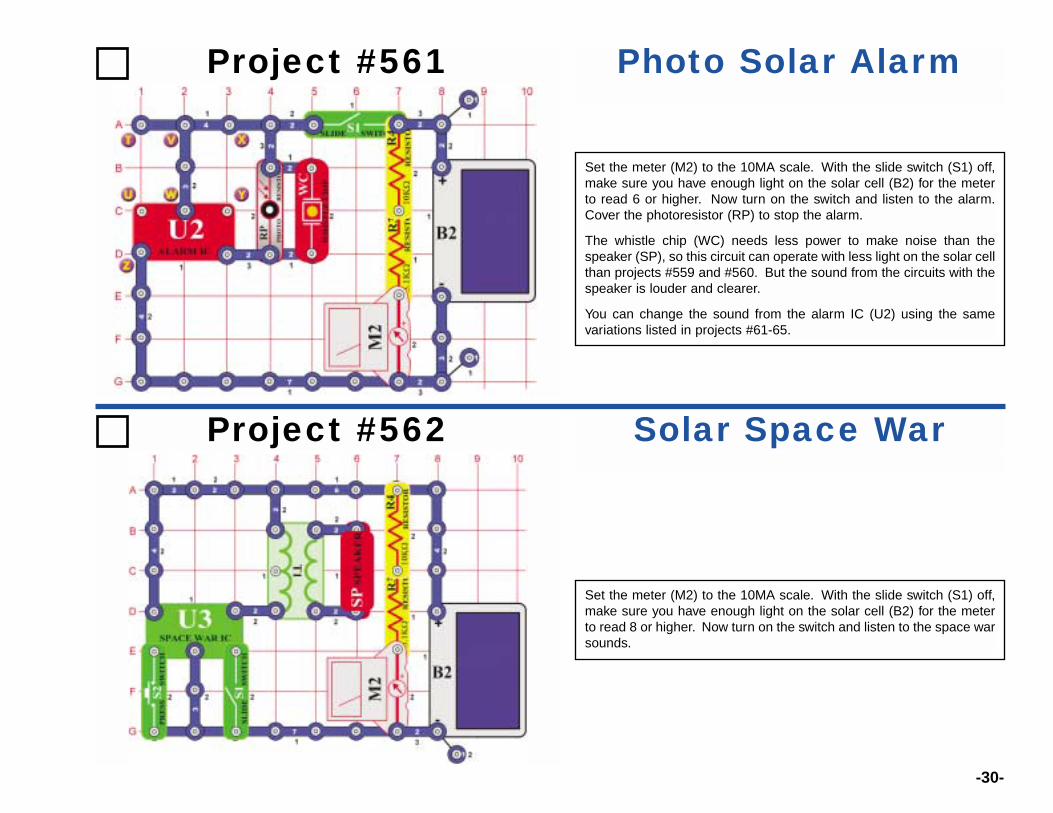
Project #561 Photo Solar Alarm
Project #562 Solar Space War
Set the meter (M2) to the 10MA scale. With the slide switch (S1) off,make sure you have enough light on the solar cell (B2) for the meterto read 8 or higher. Now turn on the switch and listen to the space warsounds.
Set the meter (M2) to the 10MA scale. With the slide switch (S1) off,make sure you have enough light on the solar cell (B2) for the meterto read 6 or higher. Now turn on the switch and listen to the alarm.Cover the photoresistor (RP) to stop the alarm.
The whistle chip (WC) needs less power to make noise than thespeaker (SP), so this circuit can operate with less light on the solar cellthan projects #559 and #560. But the sound from the circuits with thespeaker is louder and clearer.
You can change the sound from the alarm IC (U2) using the samevariations listed in projects #61-65.
-31-
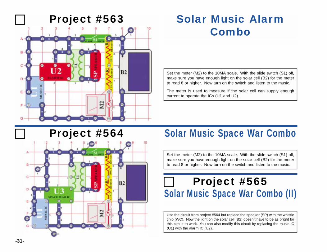
Project #563 Solar Music AlarmCombo
Project #564 Solar Music Space War Combo
Set the meter (M2) to the 10MA scale. With the slide switch (S1) off,make sure you have enough light on the solar cell (B2) for the meterto read 8 or higher. Now turn on the switch and listen to the music.
Set the meter (M2) to the 10MA scale. With the slide switch (S1) off,make sure you have enough light on the solar cell (B2) for the meterto read 8 or higher. Now turn on the switch and listen to the music.
The meter is used to measure if the solar cell can supply enoughcurrent to operate the ICs (U1 and U2).
Solar Music Space War Combo (II)
Use the circuit from project #564 but replace the speaker (SP) with the whistlechip (WC). Now the light on the solar cell (B2) doesn’t have to be as bright forthis circuit to work. You can also modify this circuit by replacing the music IC(U1) with the alarm IC (U2).
Project #565

-32-
Project #566 Solar Periodic Lights
Project #568 Solar AM RadioTransmitter
You need an AM radio for this project. Place it next to your circuit andtune the frequency to where no other station is transmitting.
Set the meter (M2) to the 10MA scale. With the slide switch (S1) off,make sure you have enough light on the solar cell (B2) for the meterto read 9 or higher. Turn on the switch and adjust the variablecapacitor (CV) for the best sound on the radio. Cover the photoresistor(RP) to change the sound pattern.
Set the meter (M2) to the 10MA scale. With the slide switch (S1) off,make sure you have enough light on the solar cell (B2) for the meterto read 9 or higher. Now turn on the switch and the LEDs (D1 and D2)will alternate being on and off.
Solar Periodic Lights (II)Project #567
Use the circuit in project #566, except remove the 3-snap between themusic (U1) and alarm (U2) ICs (base grid locations C2-C4) and add a2-snap between the music IC and the 100Ω resistor (R1) (base gridB4-C4). The circuit works the same way but the LED flashing patternsare different.

-33-
Project #569 Low Light Noisemaker
Project #570Low Light Noisemaker (II)
Use the circuit from project #569 but replacethe whistle chip (WC) with the 0.1µFcapacitor (C2) to lower the frequency of thesound. The circuit works the same way.
Project #571Low Light Noisemaker (III)
Set the meter (M2) to the 10MA scale. With the slide switch (S1) off,make sure you have light on the solar cell (B2) for the meter to read atleast 5 but less than 10.
Turn on the switch and it should make a whining sound, adjust theamount of light to the solar cell to change the frequency of the sound.Use a brighter light or partially cover the solar cell if there is no soundat all.
Use the circuit from project #569 but replacethe whistle chip (WC) with the 10µF capacitor(C3) to lower the frequency of the sound. Thecircuit works the same way but you hear aticking sound instead of a whining sound.

-34-
Project #572 Solar Oscillator
Project #574 Daylight SCR Lamp
Set the meter (M2) to the 10MA scale. Make sure you have enoughlight on the solar cell (B2) for the meter to read 3 or higher.
Turn on the slide switch (S1), the lamp (L1) stays off. Push the pressswitch (S2) and the SCR (Q3) turns on the lamp and keeps it on. Youmust turn off the slide switch to turn off the lamp.
The SCR is a controlled diode. It lets current flow in one direction, andonly after a voltage pulse is applied to its control pin. This circuit hasthe control pin connected to the press switch (S2) and solar cell, soyou can’t turn it on if the room is dark.
Set the meter (M2) to the 10MA scale. With the slide switch (S1) off, makesure you have enough light on the solar cell (B2) for the meter to read 8or higher. Now turn on the switch and adjust the variable resistor (RV).
You will hear a clicking sound like raindrops or a whine, dependingupon how much light there is.
Solar Oscillator (II)Project #573
Use the circuit from project #572 but replace the 10µF capacitor (C3)with the 0.02µF or 0.1µF capacitors (C1 and C2) to make the sound ahigh-pitch whine.

-35-
Project #575 Solar Bird Sounds
Set the meter (M2) to the 10MA scale. With the slide switch (S1) off,make sure you have enough light on the solar cell (B2) for the meterto read 8 or higher. Now turn on the switch and listen to the sound.
For variations on this circuit, replace the 100µF capacitor (C4) with the10µF capacitor (C3) or replace the speaker (SP) with the whistle chip(WC).
Project #576 Solar Bird Sounds (II)
Set the meter (M2) to the 10MA scale. With the slide switch (S1) off,make sure you have enough light on the solar cell (B2) for the meterto read 8 or higher. Now turn on the switch and listen to the sound.
For variations on this circuit, install the whistle chip (WC) above the0.02µF capacitor (C1), or install it across points A and B and removethe speaker (SP).
-36-
Project #577 SCR Solar Bomb Sounds
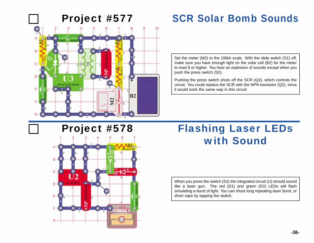
Set the meter (M2) to the 10MA scale. With the slide switch (S1) off,make sure you have enough light on the solar cell (B2) for the meterto read 8 or higher. You hear an explosion of sounds except when youpush the press switch (S2).
Pushing the press switch shuts off the SCR (Q3), which controls thecircuit. You could replace the SCR with the NPN transistor (Q2), sinceit would work the same way in this circuit.
Project #578 Flashing Laser LEDswith Sound
When you press the switch (S2) the integrated circuit (U) should soundlike a laser gun. The red (D1) and green (D2) LEDs will flashsimulating a burst of light. You can shoot long repeating laser burst, orshort zaps by tapping the switch.

-37-
Project #579 U2 with TransistorAmplifier
Project #580U2 with Transistor
Amplifier (II)
Using project #579, remove the diode (D3) tocreate a different sound.
Project #581U2 with Transistor
Amplifier (III)
Turn the switch (S1) on and the LEDs (D1 and D2) flash as thespeaker (SP) sounds. The output pulses from U2 turns transistor Q2on and off rapidly. As the transistor turns on, the speaker shorts toground and a current flows through it. The current flow through thespeaker causes it produce a sound. The LEDs show the pulsing signalfrom U2 that is turning Q2 on and off.
Using the project #579, replace U2 with U1.The circuit will now play “Happy Birthday”.
-38-
Project #582 Loud Sounds
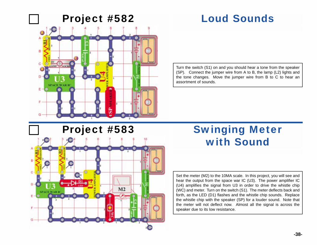
Turn the switch (S1) on and you should hear a tone from the speaker(SP). Connect the jumper wire from A to B, the lamp (L2) lights andthe tone changes. Move the jumper wire from B to C to hear anassortment of sounds.
Project #583 Swinging Meterwith Sound
Set the meter (M2) to the 10MA scale. In this project, you will see andhear the output from the space war IC (U3). The power amplifier IC(U4) amplifies the signal from U3 in order to drive the whistle chip(WC) and meter. Turn on the switch (S1). The meter deflects back andforth, as the LED (D1) flashes and the whistle chip sounds. Replacethe whistle chip with the speaker (SP) for a louder sound. Note thatthe meter will not deflect now. Almost all the signal is across thespeaker due to its low resistance.
-39-
Project #584 Motor Sound UsingTransformer
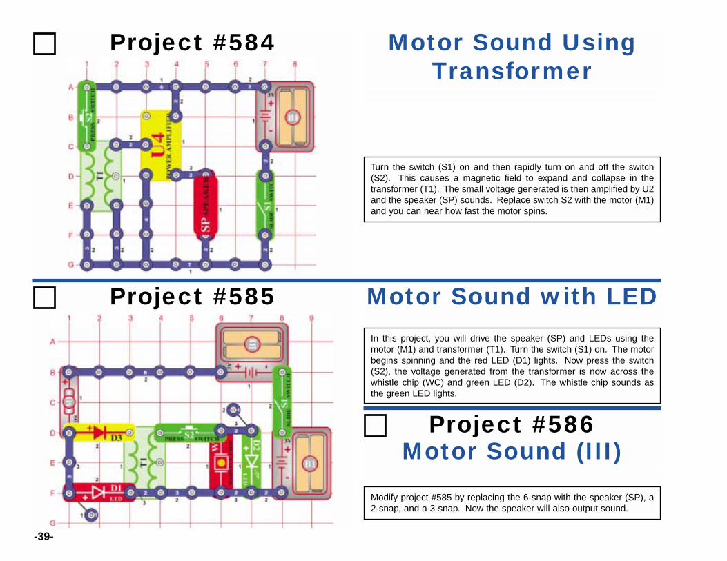
Turn the switch (S1) on and then rapidly turn on and off the switch(S2). This causes a magnetic field to expand and collapse in thetransformer (T1). The small voltage generated is then amplified by U2and the speaker (SP) sounds. Replace switch S2 with the motor (M1)and you can hear how fast the motor spins.
Project #585 Motor Sound with LEDIn this project, you will drive the speaker (SP) and LEDs using themotor (M1) and transformer (T1). Turn the switch (S1) on. The motorbegins spinning and the red LED (D1) lights. Now press the switch(S2), the voltage generated from the transformer is now across thewhistle chip (WC) and green LED (D2). The whistle chip sounds asthe green LED lights.
Motor Sound (III)Project #586
Modify project #585 by replacing the 6-snap with the speaker (SP), a2-snap, and a 3-snap. Now the speaker will also output sound.
-40-
Project #587 AC & DC Current
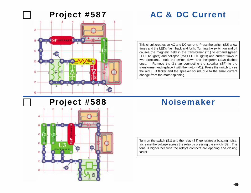
This circuit creates an AC and DC current. Press the switch (S2) a fewtimes and the LEDs flash back and forth. Turning the switch on and offcauses the magnetic field in the transformer (T1) to expand (greenLED D2 lights) and collapse (red LED D1 lights) and current flows intwo directions. Hold the switch down and the green LEDs flashesonce. Remove the 3-snap connecting the speaker (SP) to thetransformer and replace it with the motor (M1). Press the switch to seethe red LED flicker and the speaker sound, due to the small currentchange from the motor spinning.
Project #588 Noisemaker
Turn on the switch (S1) and the relay (S3) generates a buzzing noise.Increase the voltage across the relay by pressing the switch (S2). Thetone is higher because the relay’s contacts are opening and closingfaster.
-41-
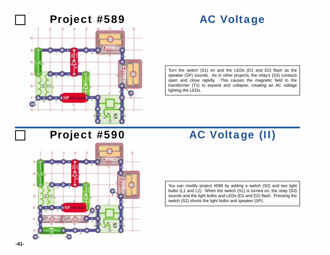
Project #589 AC Voltage
Turn the switch (S1) on and the LEDs (D1 and D2) flash as thespeaker (SP) sounds. As in other projects, the relay’s (S3) contactsopen and close rapidly. This causes the magnetic field in thetransformer (T1) to expand and collapse, creating an AC voltagelighting the LEDs.
Project #590 AC Voltage (II)
You can modify project #589 by adding a switch (S2) and two lightbulbs (L1 and L2). When the switch (S1) is turned on, the relay (S3)sounds and the light bulbs and LEDs (D1 and D2) flash. Pressing theswitch (S2) shorts the light bulbs and speaker (SP).

-42-
Project #591 AC Voltage (III)
This project is similar to project #589. When the switch (S1) is turnedon, the relay (S3) sounds and the light bulbs (L1 and L2) and LEDs(D1 and D2) flash. Now when the switch (S2) is pressed, the speaker(SP) also sounds.
Project #592 Noisemaker (II)
Turn on the switch (S1) and the relay (S3) generates a buzzing noise.Increase the voltage across the relay by pressing the switch (S2). Thetone is higher because the relay’s contacts are opening and closingfaster.

-43-
Project #594 Pulsing Motor
Turn on the switch (S1) and now you have a pulsing motor and LEDscircuit. Replace the meter (M2) with the 470µF capacitor (C5) tochange the rate the LEDs (D1 and D2) flash.
Project #593 Noisemaker (III)
Turn the switch (S1) on and the speaker (SP) sounds as the motor(M1) spins. The relay’s (S3) contacts rapidly open and close thebattery connection to the circuit causing the alarm IC (U2) sound to bedifferent.
-44-
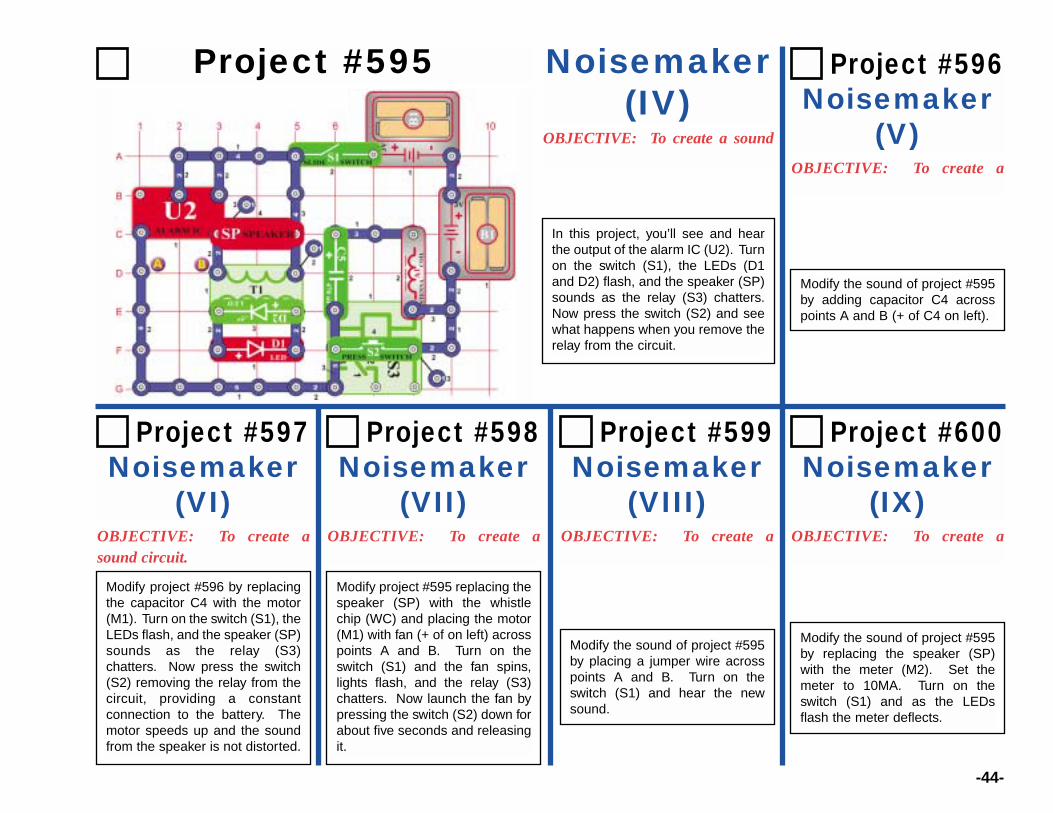
Project #595 Noisemaker(IV)
OBJECTIVE: To create a sound
Project #597Noisemaker
(VI)OBJECTIVE: To create asound circuit.
OBJECTIVE: To create a
Project #599 Noisemaker
(VIII)OBJECTIVE: To create a OBJECTIVE: To create a
Project #598 Noisemaker
(VII)
Modify project #595 replacing thespeaker (SP) with the whistlechip (WC) and placing the motor(M1) with fan (+ of on left) acrosspoints A and B. Turn on theswitch (S1) and the fan spins,lights flash, and the relay (S3)chatters. Now launch the fan bypressing the switch (S2) down forabout five seconds and releasingit.
Modify the sound of project #595by placing a jumper wire acrosspoints A and B. Turn on theswitch (S1) and hear the newsound.
Modify the sound of project #595by replacing the speaker (SP)with the meter (M2). Set themeter to 10MA. Turn on theswitch (S1) and as the LEDsflash the meter deflects.
Project #600 Noisemaker
(IX)
OBJECTIVE: To create a
Project #596 Noisemaker
(V)
Modify the sound of project #595by adding capacitor C4 acrosspoints A and B (+ of C4 on left).
In this project, you’ll see and hearthe output of the alarm IC (U2). Turnon the switch (S1), the LEDs (D1and D2) flash, and the speaker (SP)sounds as the relay (S3) chatters.Now press the switch (S2) and seewhat happens when you remove therelay from the circuit.
Modify project #596 by replacingthe capacitor C4 with the motor(M1). Turn on the switch (S1), theLEDs flash, and the speaker (SP)sounds as the relay (S3)chatters. Now press the switch(S2) removing the relay from thecircuit, providing a constantconnection to the battery. Themotor speeds up and the soundfrom the speaker is not distorted.

-45-
Project #601 Alarm Power
Project #602Alarm Power (II)
Project #603Night Sounds
In this project, the alarm IC (U2) powers the motor (M1), meter (M2)and LEDs (D1 and D2). Set the meter to the 10MA position and turnon the switch (S1). The circuit pulses the meter, motor, LEDs, andwhistle chip (WC). You can replace the meter with the speaker (SP)for a louder sound.
Remove the motor (M1) from the circuit and now the circuit pulsesaround 1Hz.
Simulate the sound of a forest at night by replacing the motor (M1) withthe whistle chip (WC) as in project #601.
-46-
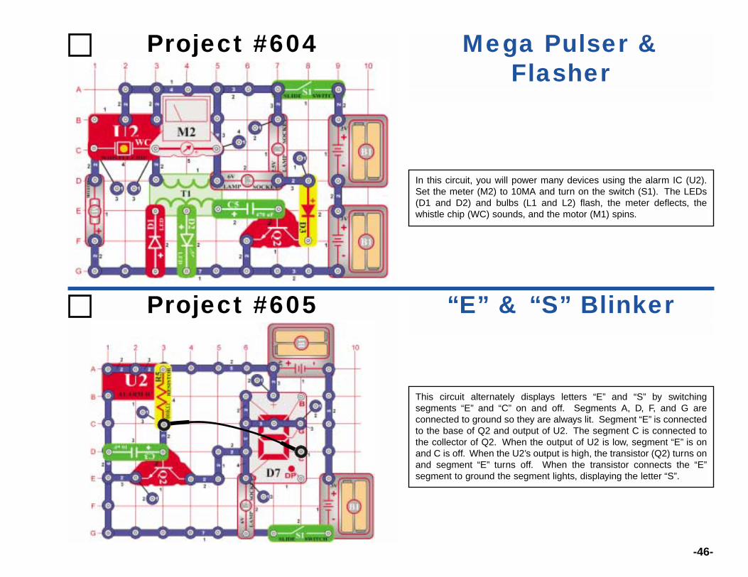
Project #604 Mega Pulser &Flasher
In this circuit, you will power many devices using the alarm IC (U2).Set the meter (M2) to 10MA and turn on the switch (S1). The LEDs(D1 and D2) and bulbs (L1 and L2) flash, the meter deflects, thewhistle chip (WC) sounds, and the motor (M1) spins.
Project #605 “E” & “S” Blinker
This circuit alternately displays letters “E” and “S” by switchingsegments “E” and “C” on and off. Segments A, D, F, and G areconnected to ground so they are always lit. Segment “E” is connectedto the base of Q2 and output of U2. The segment C is connected tothe collector of Q2. When the output of U2 is low, segment “E” is onand C is off. When the U2’s output is high, the transistor (Q2) turns onand segment “E” turns off. When the transistor connects the “E”segment to ground the segment lights, displaying the letter “S”.
-47-
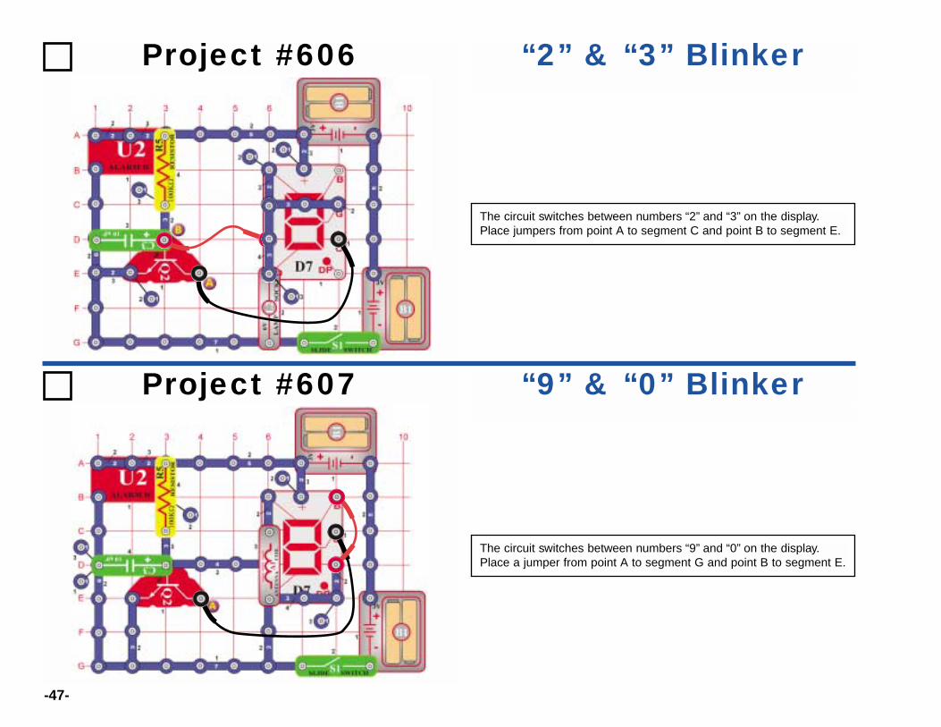
Project #606 “2” & “3” Blinker
The circuit switches between numbers “2” and “3” on the display.Place jumpers from point A to segment C and point B to segment E.
Project #607 “9” & “0” Blinker
The circuit switches between numbers “9” and “0” on the display.Place a jumper from point A to segment G and point B to segment E.
-48-
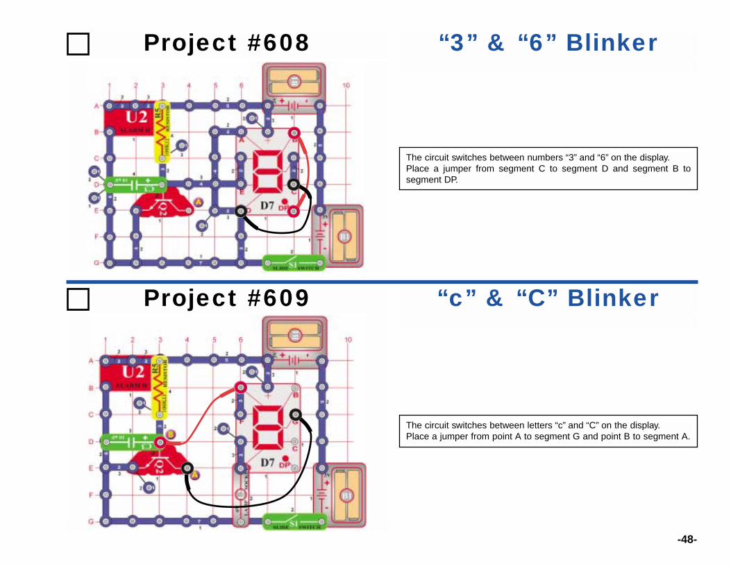
Project #608 “3” & “6” Blinker
The circuit switches between numbers “3” and “6” on the display.Place a jumper from segment C to segment D and segment B tosegment DP.
Project #609 “c” & “C” Blinker
The circuit switches between letters “c” and “C” on the display.Place a jumper from point A to segment G and point B to segment A.
-49-
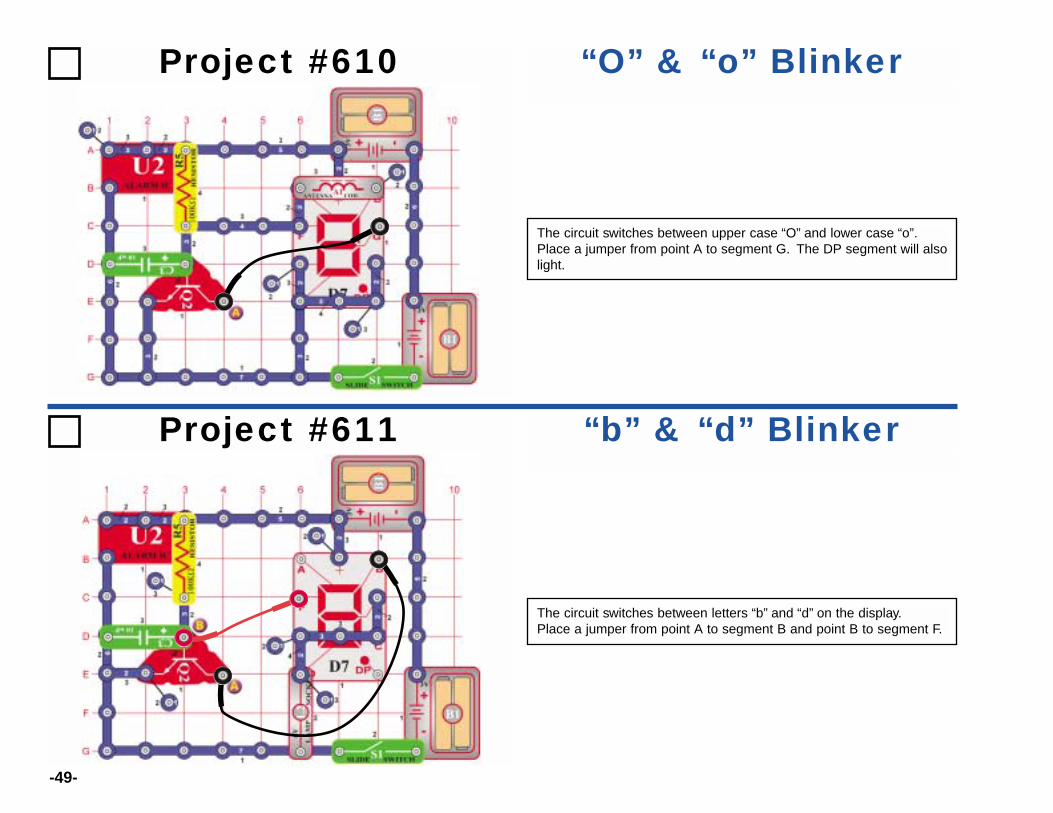
Project #610 “O” & “o” Blinker
The circuit switches between upper case “O” and lower case “o”.Place a jumper from point A to segment G. The DP segment will alsolight.
Project #611 “b” & “d” Blinker
The circuit switches between letters “b” and “d” on the display.Place a jumper from point A to segment B and point B to segment F.
-50-
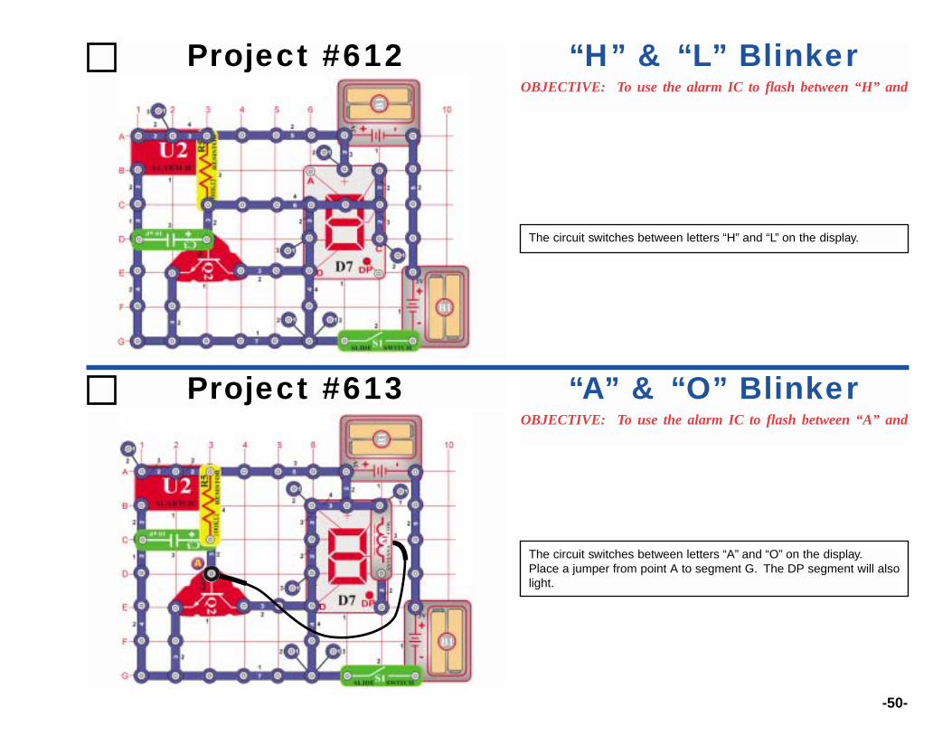
Project #612OBJECTIVE: To use the alarm IC to flash between “H” and
“H” & “L” Blinker
The circuit switches between letters “H” and “L” on the display.
Project #613OBJECTIVE: To use the alarm IC to flash between “A” and
“A” & “O” Blinker
The circuit switches between letters “A” and “O” on the display.Place a jumper from point A to segment G. The DP segment will alsolight.
-51-
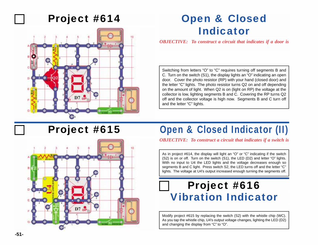
Project #614
OBJECTIVE: To construct a circuit that indicates if a door is
Open & ClosedIndicator
Switching from letters “O” to “C” requires turning off segments B andC. Turn on the switch (S1), the display lights an “O” indicating an opendoor. Cover the photo resistor (RP) with your hand (closed door) andthe letter “C” lights. The photo resistor turns Q2 on and off dependingon the amount of light. When Q2 is on (light on RP) the voltage at thecollector is low, lighting segments B and C. Covering the RP turns Q2off and the collector voltage is high now. Segments B and C turn offand the letter “C” lights.
Project #615OBJECTIVE: To construct a circuit that indicates if a switch is
Open & Closed Indicator (II)
As in project #614, the display will light an “O” or “C” indicating if the switch(S2) is on or off. Turn on the switch (S1), the LED (D2) and letter “O” lights.With no input to U4 the LED lights and the voltage decreases enough sosegments B and C light. Press switch S2, the LED turns off and the letter “C”lights. The voltage at U4’s output increased enough turning the segments off.
Vibration IndicatorProject #616
Modify project #615 by replacing the switch (S2) with the whistle chip (WC).As you tap the whistle chip, U4’s output voltage changes, lighting the LED (D2)and changing the display from “C” to “O”.

-52-
Project #617 Vibration Sounder
As the motor (M1) spins it generates an AC voltage amplified by U4.The output from U4 lights the LED (D2) and drives the transistor (Q1),sounding the speaker (SP). With the fan not installed, turn on theswitch (S1) and you hear the high tone of the spinning motor. Now,install the fan and hear the difference.
Project #618 SCR Noise Circuit
Turn on the switch (S1) and nothing happens. The SCR (Q3) connectsthe circuit to the batteries and, until the SCR’s gate goes high, thecircuit is off. Press th switch (S2) and the motor (M1) spins and theLED (D2) and bulb (L2) light. Increase the sound from the speaker(SP) by pressing S2.
-53-
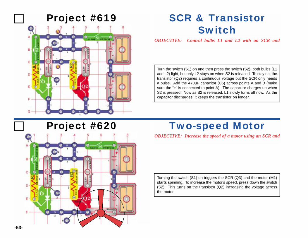
Project #619
OBJECTIVE: Control bulbs L1 and L2 with an SCR and
SCR & TransistorSwitch
Turn the switch (S1) on and then press the switch (S2), both bulbs (L1and L2) light, but only L2 stays on when S2 is released. To stay on, thetransistor (Q2) requires a continuous voltage but the SCR only needsa pulse. Add the 470µF capacitor (C5) across points A and B (makesure the “+” is connected to point A). The capacitor charges up whenS2 is pressed. Now as S2 is released, L1 slowly turns off now. As thecapacitor discharges, it keeps the transistor on longer.
Project #620OBJECTIVE: Increase the speed of a motor using an SCR and
Two-speed Motor
Turning the switch (S1) on triggers the SCR (Q3) and the motor (M1)starts spinning. To increase the motor’s speed, press down the switch(S2). This turns on the transistor (Q2) increasing the voltage acrossthe motor.
-54-
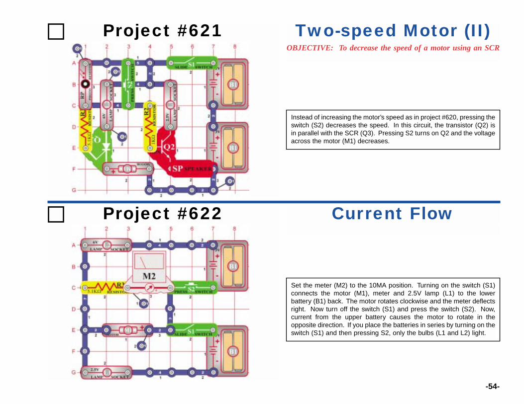
Project #621OBJECTIVE: To decrease the speed of a motor using an SCR
Two-speed Motor (II)
Instead of increasing the motor’s speed as in project #620, pressing theswitch (S2) decreases the speed. In this circuit, the transistor (Q2) isin parallel with the SCR (Q3). Pressing S2 turns on Q2 and the voltageacross the motor (M1) decreases.
Project #622 Current Flow
Set the meter (M2) to the 10MA position. Turning on the switch (S1)connects the motor (M1), meter and 2.5V lamp (L1) to the lowerbattery (B1) back. The motor rotates clockwise and the meter deflectsright. Now turn off the switch (S1) and press the switch (S2). Now,current from the upper battery causes the motor to rotate in theopposite direction. If you place the batteries in series by turning on theswitch (S1) and then pressing S2, only the bulbs (L1 and L2) light.

-55-
Project #623 AM Radiowith Power LEDs
Set the variable resistor (RV) to the middle position and turn the switch(S1) on. Tune the radio by adjusting the variable capacitor (CV). TheLEDs (D1 and D2) flicker as the sound is heard.
Project #624 Space War ICRecording
The circuit records the sounds from the space war IC (U3) into therecording IC (U6). Turn on the switch (S1) and the first beep indicatesthat the IC has begun recording. When you hear two beeps, therecording has stopped. Turn off the switch (S1) and press the switch(S2). You will hear the recording of the space war IC before each songis played.
Place the 2-snap from points A and B onto C and D. Now record adifferent sound from U3.
-56-
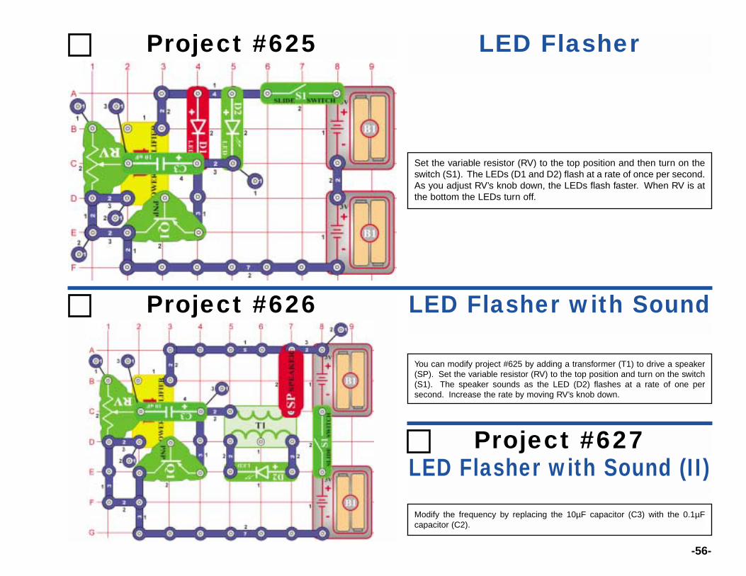
Project #625 LED Flasher
Set the variable resistor (RV) to the top position and then turn on theswitch (S1). The LEDs (D1 and D2) flash at a rate of once per second.As you adjust RV’s knob down, the LEDs flash faster. When RV is atthe bottom the LEDs turn off.
Project #626 LED Flasher with Sound
You can modify project #625 by adding a transformer (T1) to drive a speaker(SP). Set the variable resistor (RV) to the top position and turn on the switch(S1). The speaker sounds as the LED (D2) flashes at a rate of one persecond. Increase the rate by moving RV’s knob down.
LED Flasher with Sound (II)Project #627
Modify the frequency by replacing the 10µF capacitor (C3) with the 0.1µFcapacitor (C2).
-57-
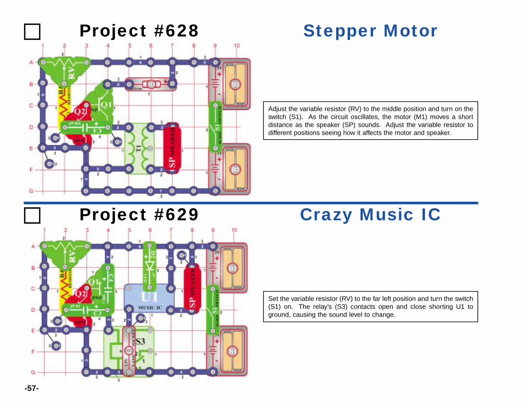
Project #628 Stepper Motor
Adjust the variable resistor (RV) to the middle position and turn on theswitch (S1). As the circuit oscillates, the motor (M1) moves a shortdistance as the speaker (SP) sounds. Adjust the variable resistor todifferent positions seeing how it affects the motor and speaker.
Project #629 Crazy Music IC
Set the variable resistor (RV) to the far left position and turn the switch(S1) on. The relay’s (S3) contacts open and close shorting U1 toground, causing the sound level to change.
-58-
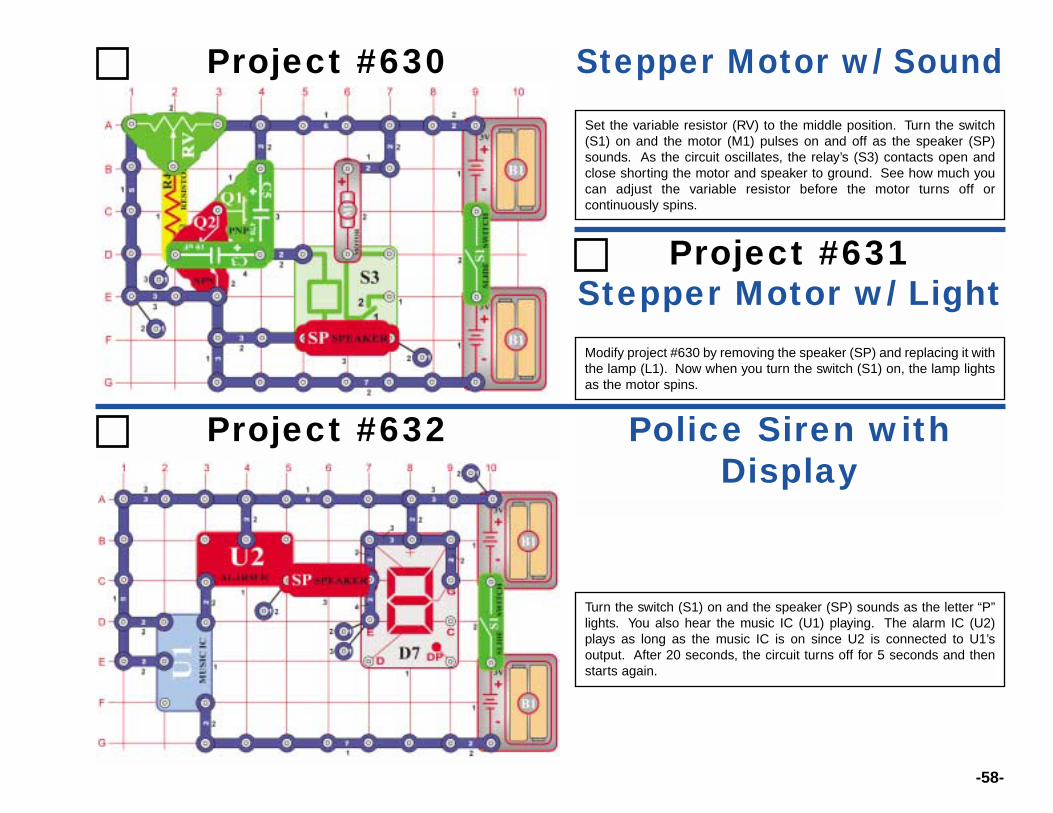
Project #630 Stepper Motor w/ Sound
Modify project #630 by removing the speaker (SP) and replacing it withthe lamp (L1). Now when you turn the switch (S1) on, the lamp lightsas the motor spins.
Set the variable resistor (RV) to the middle position. Turn the switch(S1) on and the motor (M1) pulses on and off as the speaker (SP)sounds. As the circuit oscillates, the relay’s (S3) contacts open andclose shorting the motor and speaker to ground. See how much youcan adjust the variable resistor before the motor turns off orcontinuously spins.
Project #631Stepper Motor w/ Light
Project #632 Police Siren withDisplay
Turn the switch (S1) on and the speaker (SP) sounds as the letter “P”lights. You also hear the music IC (U1) playing. The alarm IC (U2)plays as long as the music IC is on since U2 is connected to U1’soutput. After 20 seconds, the circuit turns off for 5 seconds and thenstarts again.
-59-
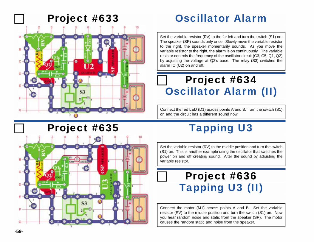
Project #633 Oscillator AlarmSet the variable resistor (RV) to the far left and turn the switch (S1) on.The speaker (SP) sounds only once. Slowly move the variable resistorto the right, the speaker momentarily sounds. As you move thevariable resistor to the right, the alarm is on continuously. The variableresistor controls the frequency of the oscillator circuit (C3, C5, Q1, Q2)by adjusting the voltage at Q2’s base. The relay (S3) switches thealarm IC (U2) on and off.
Project #635 Tapping U3Set the variable resistor (RV) to the middle position and turn the switch(S1) on. This is another example using the oscillator that switches thepower on and off creating sound. Alter the sound by adjusting thevariable resistor.
Oscillator Alarm (II)Project #634
Connect the red LED (D1) across points A and B. Turn the switch (S1)on and the circuit has a different sound now.
Tapping U3 (II)Project #636
Connect the motor (M1) across points A and B. Set the variableresistor (RV) to the middle position and turn the switch (S1) on. Nowyou hear random noise and static from the speaker (SP). The motorcauses the random static and noise from the speaker.
-60-
Project #637 Adjustable Beeper
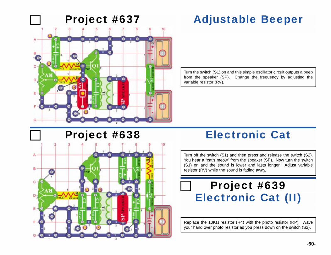
Turn the switch (S1) on and this simple oscillator circuit outputs a beepfrom the speaker (SP). Change the frequency by adjusting thevariable resistor (RV).
Project #638 Electronic CatTurn off the switch (S1) and then press and release the switch (S2).You hear a “cat’s meow” from the speaker (SP). Now turn the switch(S1) on and the sound is lower and lasts longer. Adjust variableresistor (RV) while the sound is fading away.
Electronic Cat (II)Project #639
Replace the 10KΩ resistor (R4) with the photo resistor (RP). Waveyour hand over photo resistor as you press down on the switch (S2).
-61-
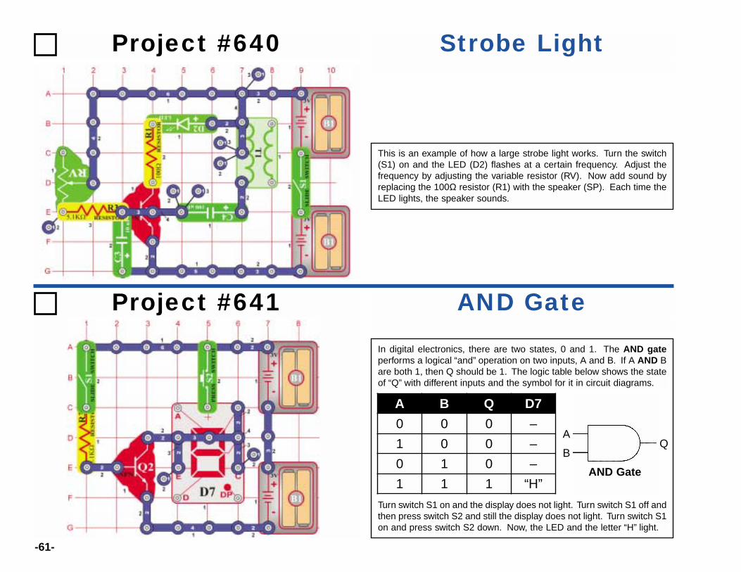
Project #640 Strobe Light
This is an example of how a large strobe light works. Turn the switch(S1) on and the LED (D2) flashes at a certain frequency. Adjust thefrequency by adjusting the variable resistor (RV). Now add sound byreplacing the 100Ω resistor (R1) with the speaker (SP). Each time theLED lights, the speaker sounds.
Project #641 AND GateIn digital electronics, there are two states, 0 and 1. The AND gateperforms a logical “and” operation on two inputs, A and B. If A AND Bare both 1, then Q should be 1. The logic table below shows the stateof “Q” with different inputs and the symbol for it in circuit diagrams.
Turn switch S1 on and the display does not light. Turn switch S1 off andthen press switch S2 and still the display does not light. Turn switch S1on and press switch S2 down. Now, the LED and the letter “H” light.
A B Q D7
0 0 0 –
1 0 0 –
0 1 0 –
1 1 1 “H”
A
BQ
AND Gate
-62-
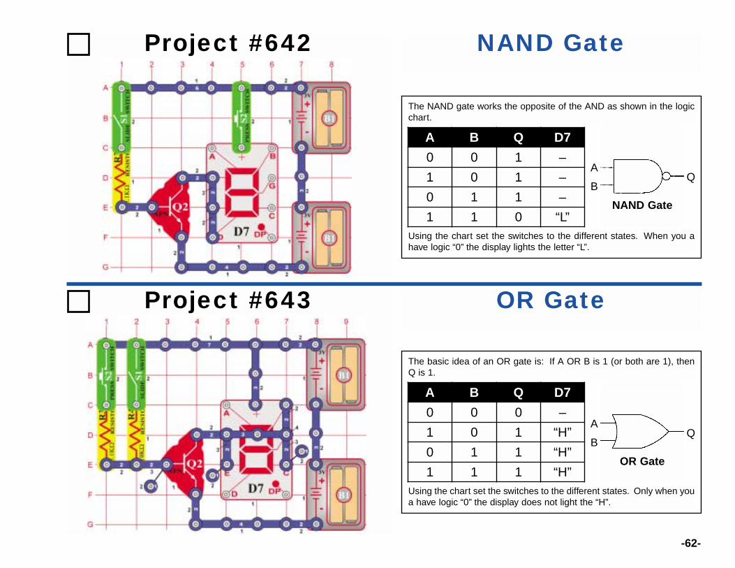
Project #642 NAND Gate
Project #643 OR Gate
The NAND gate works the opposite of the AND as shown in the logicchart.
Using the chart set the switches to the different states. When you ahave logic “0” the display lights the letter “L”.
The basic idea of an OR gate is: If A OR B is 1 (or both are 1), thenQ is 1.
Using the chart set the switches to the different states. Only when youa have logic “0” the display does not light the “H”.
A B Q D7
0 0 1 –
1 0 1 –
0 1 1 –
1 1 0 “L”
A B Q D7
0 0 0 –
1 0 1 “H”
0 1 1 “H”
1 1 1 “H”
A
BQ
NAND Gate
A
BQ
OR Gate

-63-
Project #644 NOR Gate
Project #645OBJECTIVE: To demonstrate the operations of the “exclusive
XOR Gate
The NOR gate works the opposite of the OR. Using the chart set theswitches to the different states. The display lights the letter “L” wheneither switch is turned on.
In an XOR gate the output “Q” is only high when inputs “A” or “B” is sethigh (1).Using the chart set the switches to the different states. The displaylights the letter “H” only when either switch is turned on.
A B Q D7
0 0 1 –
1 0 0 “L”
0 1 0 “L”
1 1 0 “L”
A B Q D7
0 0 0 –
1 0 1 “H”
0 1 1 “H”
1 1 0 –
A
BQ
XOR Gate
A
BQ
NOR Gate
-64-
Project #646 High Pitch Oscillator
Project #648Low Pitch
Oscillator (II)
Project #649Low Pitch
Oscillator (III)
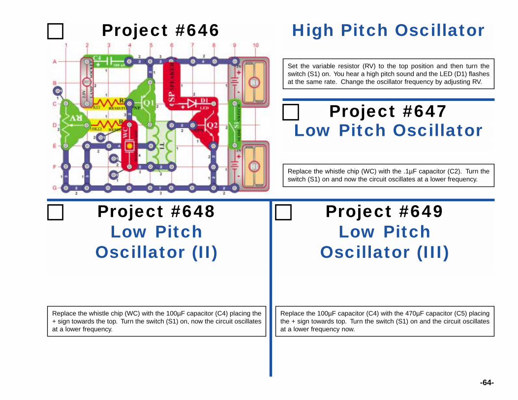
Replace the whistle chip (WC) with the 100µF capacitor (C4) placing the+ sign towards the top. Turn the switch (S1) on, now the circuit oscillatesat a lower frequency.
Replace the 100µF capacitor (C4) with the 470µF capacitor (C5) placingthe + sign towards top. Turn the switch (S1) on and the circuit oscillatesat a lower frequency now.
Set the variable resistor (RV) to the top position and then turn theswitch (S1) on. You hear a high pitch sound and the LED (D1) flashesat the same rate. Change the oscillator frequency by adjusting RV.
Low Pitch OscillatorProject #647
Replace the whistle chip (WC) with the .1µF capacitor (C2). Turn theswitch (S1) on and now the circuit oscillates at a lower frequency.
-65-
Project #650 Segment Jumper
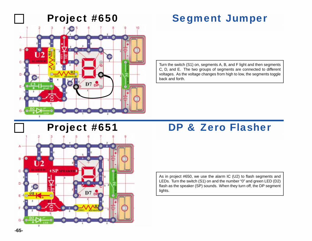
Turn the switch (S1) on, segments A, B, and F light and then segmentsC, D, and E. The two groups of segments are connected to differentvoltages. As the voltage changes from high to low, the segments toggleback and forth.
Project #651 DP & Zero Flasher
As in project #650, we use the alarm IC (U2) to flash segments andLEDs. Turn the switch (S1) on and the number “0” and green LED (D2)flash as the speaker (SP) sounds. When they turn off, the DP segmentlights.
Project #652 Stepper Motor withLamp & LEDs
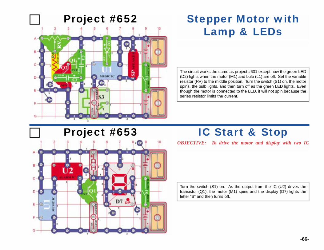
The circuit works the same as project #631 except now the green LED(D2) lights when the motor (M1) and bulb (L1) are off. Set the variableresistor (RV) to the middle position. Turn the switch (S1) on, the motorspins, the bulb lights, and then turn off as the green LED lights. Eventhough the motor is connected to the LED, it will not spin because theseries resistor limits the current.
-66-
Project #653OBJECTIVE: To drive the motor and display with two IC
IC Start & Stop
Turn the switch (S1) on. As the output from the IC (U2) drives thetransistor (Q1), the motor (M1) spins and the display (D7) lights theletter “S” and then turns off.

-67-
Project #654 IC Motor Speed
Turn the switch (S1) on. As the output from the IC (U2) drives thetransistor (Q1), the motor (M1) spins and the display (D7) lights theletter “S”. Instead of turning off as in project #653, the motor slowsdown and the red LED (D1) lights.
Modify the circuit by placing a jumper wire across points A and B. Nowthe circuit pulses and then runs consciously for a short time.
Project #655OBJECTIVE: To use the alarm IC to drive the motor, speaker,
Sound & Light Flasher
Turn the switch (S1) on and the speaker (SP) outputs the sounds fromthe alarm IC (U2). The IC also drives the transistor (Q1) causing themotor (M1) to spin and lights to flash.
-68-
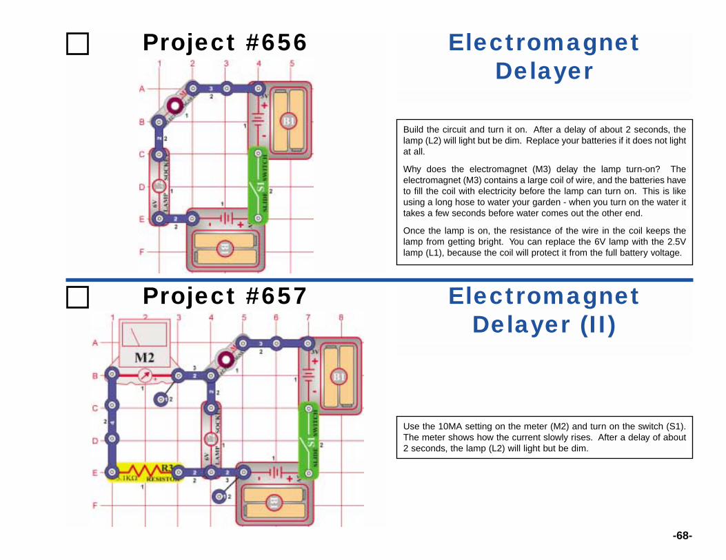
Project #656 ElectromagnetDelayer
Build the circuit and turn it on. After a delay of about 2 seconds, thelamp (L2) will light but be dim. Replace your batteries if it does not lightat all.
Why does the electromagnet (M3) delay the lamp turn-on? Theelectromagnet (M3) contains a large coil of wire, and the batteries haveto fill the coil with electricity before the lamp can turn on. This is likeusing a long hose to water your garden - when you turn on the water ittakes a few seconds before water comes out the other end.
Once the lamp is on, the resistance of the wire in the coil keeps thelamp from getting bright. You can replace the 6V lamp with the 2.5Vlamp (L1), because the coil will protect it from the full battery voltage.
Project #657 ElectromagnetDelayer (II)
Use the 10MA setting on the meter (M2) and turn on the switch (S1).The meter shows how the current slowly rises. After a delay of about2 seconds, the lamp (L2) will light but be dim.
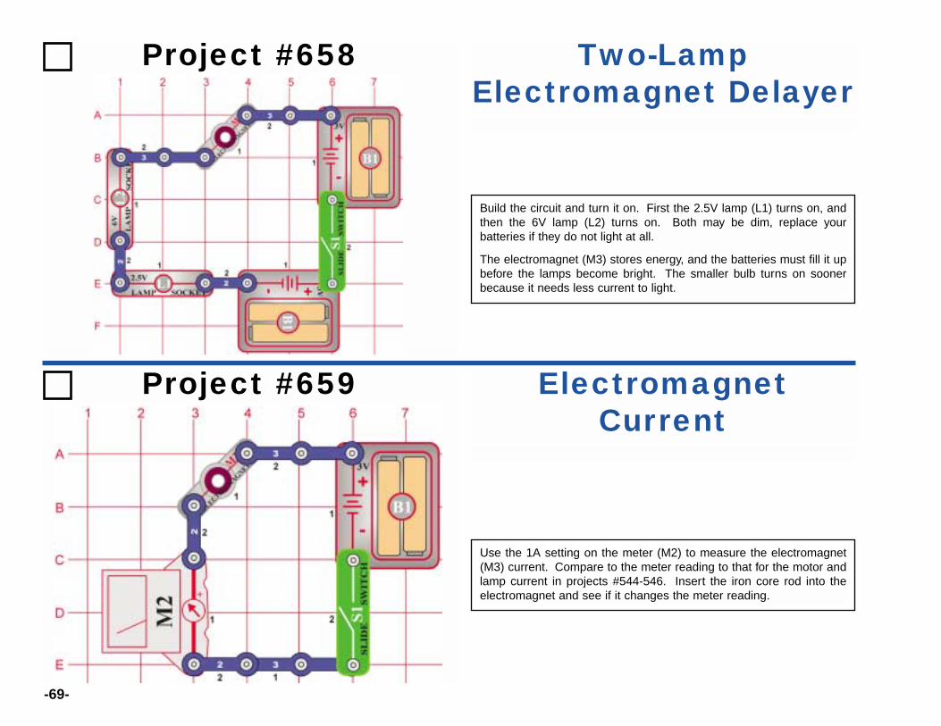
-69-
Project #658 Two-LampElectromagnet Delayer
Build the circuit and turn it on. First the 2.5V lamp (L1) turns on, andthen the 6V lamp (L2) turns on. Both may be dim, replace yourbatteries if they do not light at all.
The electromagnet (M3) stores energy, and the batteries must fill it upbefore the lamps become bright. The smaller bulb turns on soonerbecause it needs less current to light.
Project #659 ElectromagnetCurrent
Use the 1A setting on the meter (M2) to measure the electromagnet(M3) current. Compare to the meter reading to that for the motor andlamp current in projects #544-546. Insert the iron core rod into theelectromagnet and see if it changes the meter reading.
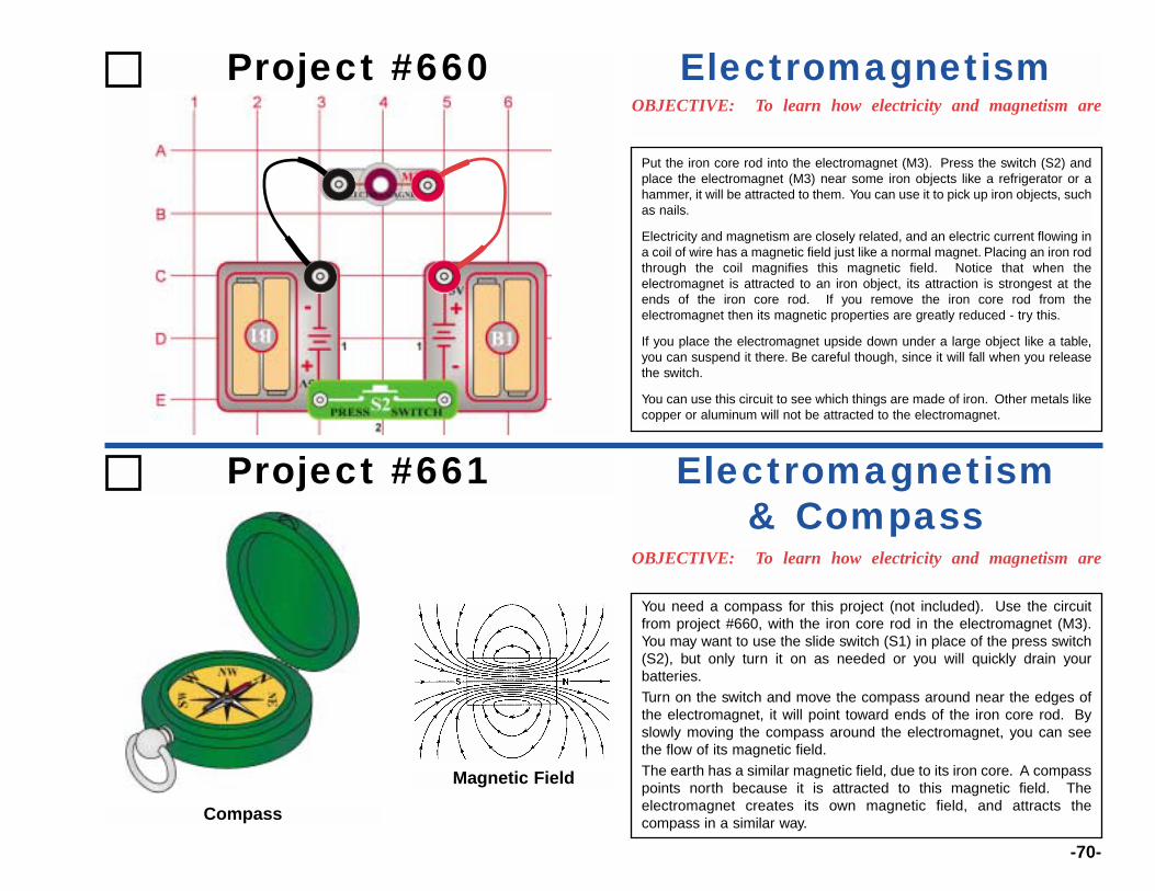
-70-
Project #660OBJECTIVE: To learn how electricity and magnetism are
Electromagnetism
Project #661
OBJECTIVE: To learn how electricity and magnetism are
Electromagnetism & Compass
You need a compass for this project (not included). Use the circuitfrom project #660, with the iron core rod in the electromagnet (M3).You may want to use the slide switch (S1) in place of the press switch(S2), but only turn it on as needed or you will quickly drain yourbatteries.Turn on the switch and move the compass around near the edges ofthe electromagnet, it will point toward ends of the iron core rod. Byslowly moving the compass around the electromagnet, you can seethe flow of its magnetic field.The earth has a similar magnetic field, due to its iron core. A compasspoints north because it is attracted to this magnetic field. Theelectromagnet creates its own magnetic field, and attracts thecompass in a similar way.
Put the iron core rod into the electromagnet (M3). Press the switch (S2) andplace the electromagnet (M3) near some iron objects like a refrigerator or ahammer, it will be attracted to them. You can use it to pick up iron objects, suchas nails.
Electricity and magnetism are closely related, and an electric current flowing ina coil of wire has a magnetic field just like a normal magnet. Placing an iron rodthrough the coil magnifies this magnetic field. Notice that when theelectromagnet is attracted to an iron object, its attraction is strongest at theends of the iron core rod. If you remove the iron core rod from theelectromagnet then its magnetic properties are greatly reduced - try this.
If you place the electromagnet upside down under a large object like a table,you can suspend it there. Be careful though, since it will fall when you releasethe switch.
You can use this circuit to see which things are made of iron. Other metals likecopper or aluminum will not be attracted to the electromagnet.
Magnetic Field
Compass

Use the circuit from project #660, with the ironcore rod in the electromagnet (M3). Press theswitch (S2) and use the electromagnet to pickup some paperclips, they will be attracted toboth ends of the iron core rod. See how manypaperclips you can lift at once.
Snap two 2-snaps around a paperclip andlift them with the electromagnet, as shownhere on the left.
The magnetic field created by the electromagnet occurs in a loop, and isstrongest in the iron core rod in the middle. You can see this loop withsome paperclips:
You can also use the paperclip to lift the iron core rod up from theelectromagnet.
See what other small objects you can pick up. You can only pick up thingsmade of iron, not just any metal.
-71-
Project #662 Electromagnetism & Paperclips
Project #663Electromagnet Suction
An electric current flowing in a coil of wire has a magnetic field, whichtries to suck iron objects into its center. You can see this using the circuitfrom project #660.
Lay the electromagnet on its side with the iron core rod sticking out abouthalf way, and press the switch. The iron rod gets sucked into the center.
A lighter iron object will show this better. Take a paperclip and straightenit out, then bend it in half.
Place the bent paperclip next to the electromagnet and turn on the switchto see it get sucked in. Gently pull it out to feel how much suction theelectromagnet has.
Try sucking up other thin iron objects, like nails.

-72-
Project #664OBJECTIVE: To show how electricity can lift things using
Electromagnet Tower
Project #665OBJECTIVE: To learn how electricity and magnetism are
Paperclip Compass
Use the circuit from project #664, but place the iron core rod in theelectromagnet. You may want to use the slide switch (S1) in place ofthe press switch (S2), but only turn it on as needed or you will quicklydrain your batteries.
Slide two paperclips together, using their loops.
Turn on the switch and hold the paperclips just above theelectromagnet, without them touching the iron core rod. Watch howthe lower paperclip is drawn toward the iron core rod, and will pointtowards it just like a compass.
This circuit gives a dramatic demonstration of howthe electromagnet can suck up a paperclip. Takea paperclip and straighten it out, then bend it inhalf. Drop it into the electromagnet center, andthen press the switch several times. Thepaperclip gets sucked into the center of theelectromagnet and stays suspended there untilyou release the switch.
Add two more 1-snaps under the electromagnetto make it higher, and try this again. Then trysucking up other thin iron objects, like nails.
Straighten andbend paperclip
Drop in
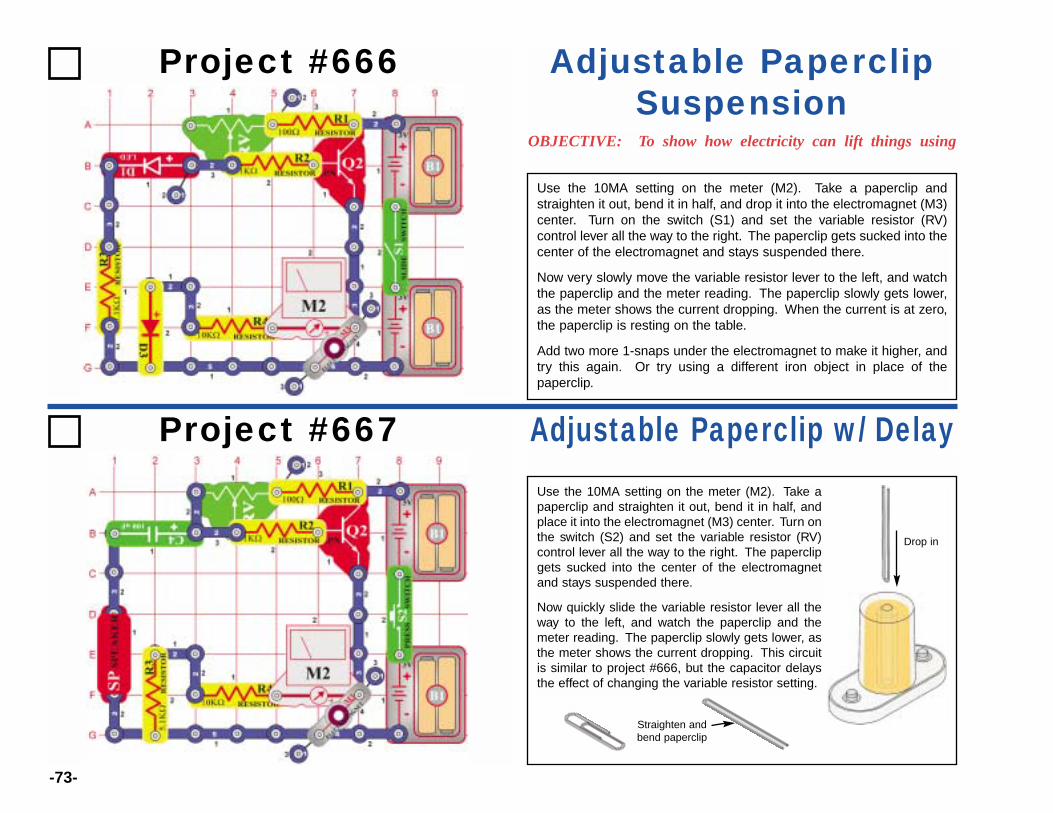
-73-
Project #666
OBJECTIVE: To show how electricity can lift things using
Adjustable PaperclipSuspension
Project #667 Adjustable Paperclip w/ DelayUse the 10MA setting on the meter (M2). Take apaperclip and straighten it out, bend it in half, andplace it into the electromagnet (M3) center. Turn onthe switch (S2) and set the variable resistor (RV)control lever all the way to the right. The paperclipgets sucked into the center of the electromagnetand stays suspended there.
Now quickly slide the variable resistor lever all theway to the left, and watch the paperclip and themeter reading. The paperclip slowly gets lower, asthe meter shows the current dropping. This circuitis similar to project #666, but the capacitor delaysthe effect of changing the variable resistor setting.
Use the 10MA setting on the meter (M2). Take a paperclip andstraighten it out, bend it in half, and drop it into the electromagnet (M3)center. Turn on the switch (S1) and set the variable resistor (RV)control lever all the way to the right. The paperclip gets sucked into thecenter of the electromagnet and stays suspended there.
Now very slowly move the variable resistor lever to the left, and watchthe paperclip and the meter reading. The paperclip slowly gets lower,as the meter shows the current dropping. When the current is at zero,the paperclip is resting on the table.
Add two more 1-snaps under the electromagnet to make it higher, andtry this again. Or try using a different iron object in place of thepaperclip.
Drop in
Straighten andbend paperclip

-74-
Project #668
OBJECTIVE: To show how electricity can lift things using
PhotoresistorPaperclip Suspension
Project #669OBJECTIVE: To show how electricity can lift things using
Paperclip Oscillator
Take a paperclip and straighten it out, bend it inhalf, and place it into the electromagnet (M3)center. Turn on the switch (S1), and set thevariable resistor (RV) control lever to the right.The paperclip gets sucked into the center of theelectromagnet and stays suspended there. Movethe variable resistor lever to the left, and thepaperclip falls.
Now for the fun part: Slowly slide the variableresistor lever until you find a spot where thepaperclip is bouncing up and down. There will bea clicking sound from the relay.
Take a paperclip and straighten it out, bend it in half, and place it intothe electromagnet (M3) center. Turn on the switch (S1), the paperclipgets sucked into the center of the electromagnet and stays suspendedthere.
Now move the variable resistor (RV) control lever around while wavingyour hand over the photoresistor (RP). Depending on the variableresistor setting, sometimes covering the photoresistor causes thepaperclip to fall and sometimes it doesn’t. You can also adjust the lightto set the paperclip to different heights.
Drop in
Straighten andbend paperclip
Drop in
Straighten and bend paperclip
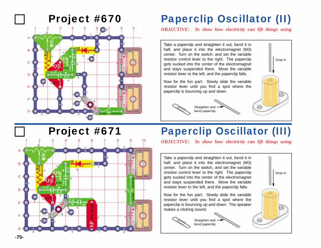
-75-
Project #670OBJECTIVE: To show how electricity can lift things using
Paperclip Oscillator (II)
Project #671OBJECTIVE: To show how electricity can lift things using
Paperclip Oscillator (III)
Take a paperclip and straighten it out, bend it inhalf, and place it into the electromagnet (M3)center. Turn on the switch, and set the variableresistor control lever to the right. The paperclipgets sucked into the center of the electromagnetand stays suspended there. Move the variableresistor lever to the left, and the paperclip falls.
Now for the fun part: Slowly slide the variableresistor lever until you find a spot where thepaperclip is bouncing up and down. The speakermakes a clicking sound.
Take a paperclip and straighten it out, bend it inhalf, and place it into the electromagnet (M3)center. Turn on the switch, and set the variableresistor control lever to the right. The paperclipgets sucked into the center of the electromagnetand stays suspended there. Move the variableresistor lever to the left, and the paperclip falls.
Now for the fun part: Slowly slide the variableresistor lever until you find a spot where thepaperclip is bouncing up and down.
Drop in
Straighten andbend paperclip
Drop in
Straighten andbend paperclip
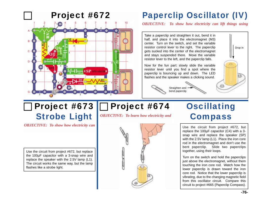
-76-
Project #672OBJECTIVE: To show how electricity can lift things using
Paperclip Oscillator (IV)
OBJECTIVE: To show how electricity can
Take a paperclip and straighten it out, bend it inhalf, and place it into the electromagnet (M3)center. Turn on the switch, and set the variableresistor control lever to the right. The paperclipgets sucked into the center of the electromagnetand stays suspended there. Move the variableresistor lever to the left, and the paperclip falls.
Now for the fun part: slowly slide the variableresistor lever until you find a spot where thepaperclip is bouncing up and down. The LEDflashes and the speaker makes a clicking sound.
Drop in
Straighten andbend paperclip
Project #673Strobe Light OBJECTIVE: To learn how electricity and
OscillatingCompass
Use the circuit from project #672, but replacethe 100µF capacitor with a 3-snap wire andreplace the speaker with the 2.5V lamp (L1).The circuit works the same way, but the lampflashes like a strobe light.
Project #674
Use the circuit from project #672, butreplace the 100µF capacitor (C4) with a 3-snap wire and replace the speaker (SP)with the 2.5V lamp (L1). Place the iron corerod in the electromagnet and don’t use thebent paperclip. Slide two paperclipstogether, using their loops.
Turn on the switch and hold the paperclipsjust above the electromagnet, without themtouching the iron core rod. Watch how thelower paperclip is drawn toward the ironcore rod. Notice that the lower paperclip isvibrating, due to the changing magnetic fieldfrom this oscillator circuit. Compare thiscircuit to project #665 (Paperclip Compass).
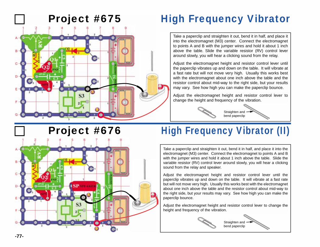
-77-
Project #675 High Frequency Vibrator
Project #676 High Frequency Vibrator (II)
Take a paperclip and straighten it out, bend it in half, and place itinto the electromagnet (M3) center. Connect the electromagnetto points A and B with the jumper wires and hold it about 1 inchabove the table. Slide the variable resistor (RV) control leveraround slowly, you will hear a clicking sound from the relay.
Adjust the electromagnet height and resistor control lever untilthe paperclip vibrates up and down on the table. It will vibrate ata fast rate but will not move very high. Usually this works bestwith the electromagnet about one inch above the table and theresistor control about mid-way to the right side, but your resultsmay vary. See how high you can make the paperclip bounce.
Adjust the electromagnet height and resistor control lever tochange the height and frequency of the vibration.
Take a paperclip and straighten it out, bend it in half, and place it into theelectromagnet (M3) center. Connect the electromagnet to points A and Bwith the jumper wires and hold it about 1 inch above the table. Slide thevariable resistor (RV) control lever around slowly, you will hear a clickingsound from the relay and speaker.
Adjust the electromagnet height and resistor control lever until thepaperclip vibrates up and down on the table. It will vibrate at a fast ratebut will not move very high. Usually this works best with the electromagnetabout one inch above the table and the resistor control about mid-way tothe right side, but your results may vary. See how high you can make thepaperclip bounce.
Adjust the electromagnet height and resistor control lever to change theheight and frequency of the vibration.
Straighten andbend paperclip
Straighten andbend paperclip
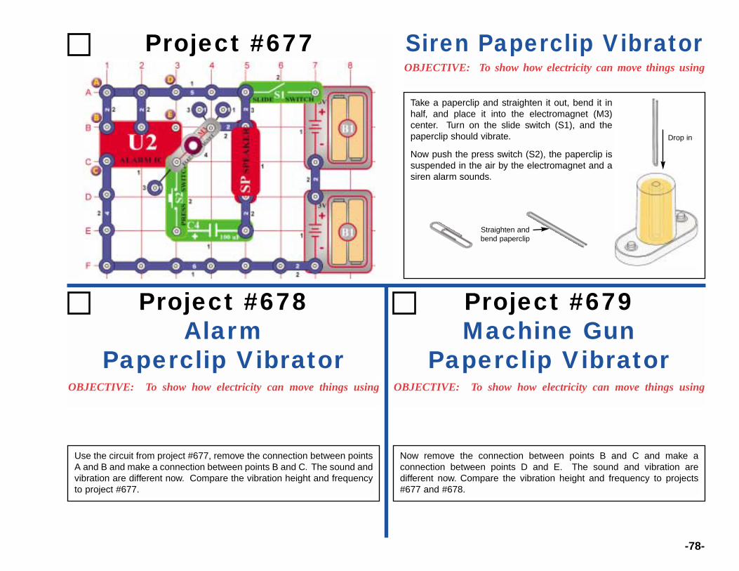
-78-
Project #677OBJECTIVE: To show how electricity can move things using
Siren Paperclip Vibrator
Take a paperclip and straighten it out, bend it inhalf, and place it into the electromagnet (M3)center. Turn on the slide switch (S1), and thepaperclip should vibrate.
Now push the press switch (S2), the paperclip issuspended in the air by the electromagnet and asiren alarm sounds.
Drop in
Straighten andbend paperclip
Project #678Alarm
Paperclip VibratorOBJECTIVE: To show how electricity can move things using OBJECTIVE: To show how electricity can move things using
Project #679Machine Gun
Paperclip Vibrator
Use the circuit from project #677, remove the connection between pointsA and B and make a connection between points B and C. The sound andvibration are different now. Compare the vibration height and frequencyto project #677.
Now remove the connection between points B and C and make aconnection between points D and E. The sound and vibration aredifferent now. Compare the vibration height and frequency to projects#677 and #678.

-79-
Project #680OBJECTIVE: To show how electricity can move things using
Alarm Vibrator w/ LED
Take a paperclip and straighten it out, bend it inhalf, and place it into the electromagnet (M3)center. Turn on the slide switch (S1), and thepaperclip should vibrate and LED (D1) flashes.
Now push the press switch (S2), the paperclip issucked up by the electromagnet and a sirenalarm sounds.
You can replace the speaker (SP) with the whistlechip (WC) to change the sound.
Drop in
Straighten andbend paperclip
Project #681OBJECTIVE: To show how electricity can move things using
Alarm Vibrator w/ LED (II)
Take a paperclip and straighten it out, bend it inhalf, and place it into the electromagnet (M3)center. Turn on the slide switch (S1), and thepaperclip should vibrate.
Now push the press switch (S2), the paperclip issucked up by the electromagnet and the LED(D1) flashes.
Drop in
Straighten andbend paperclip
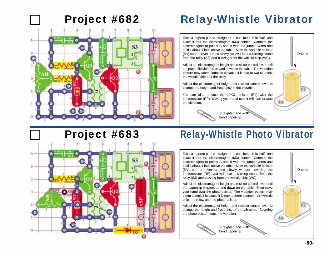
-80-
Project #682 Relay-Whistle VibratorTake a paperclip and straighten it out, bend it in half, andplace it into the electromagnet (M3) center. Connect theelectromagnet to points A and B with the jumper wires andhold it about 1 inch above the table. Slide the variable resistor(RV) control lever around slowly, you will hear a clicking soundfrom the relay (S3) and buzzing from the whistle chip (WC).
Adjust the electromagnet height and resistor control lever untilthe paperclip vibrates up and down on the table. The vibrationpattern may seem complex because it is due to two sources:the whistle chip and the relay.
Adjust the electromagnet height and resistor control lever tochange the height and frequency of the vibration.
You can also replace the 10KΩ resistor (R4) with thephotoresistor (RP). Waving your hand over it will start or stopthe vibration.
Drop in
Straighten andbend paperclip
Project #683 Relay-Whistle Photo VibratorTake a paperclip and straighten it out, bend it in half, andplace it into the electromagnet (M3) center. Connect theelectromagnet to points A and B with the jumper wires andhold it about 1 inch above the table. Slide the variable resistor(RV) control lever around slowly without covering thephotoresistor (RP), you will hear a clicking sound from therelay (S3) and buzzing from the whistle chip (WC).
Adjust the electromagnet height and resistor control lever untilthe paperclip vibrates up and down on the table. Then waveyour hand over the photoresistor. The vibration pattern mayseem complex because it is due to three sources: the whistlechip, the relay, and the photoresistor.
Adjust the electromagnet height and resistor control lever tochange the height and frequency of the vibration. Coveringthe photoresistor stops the vibration.
Drop in
Straighten andbend paperclip
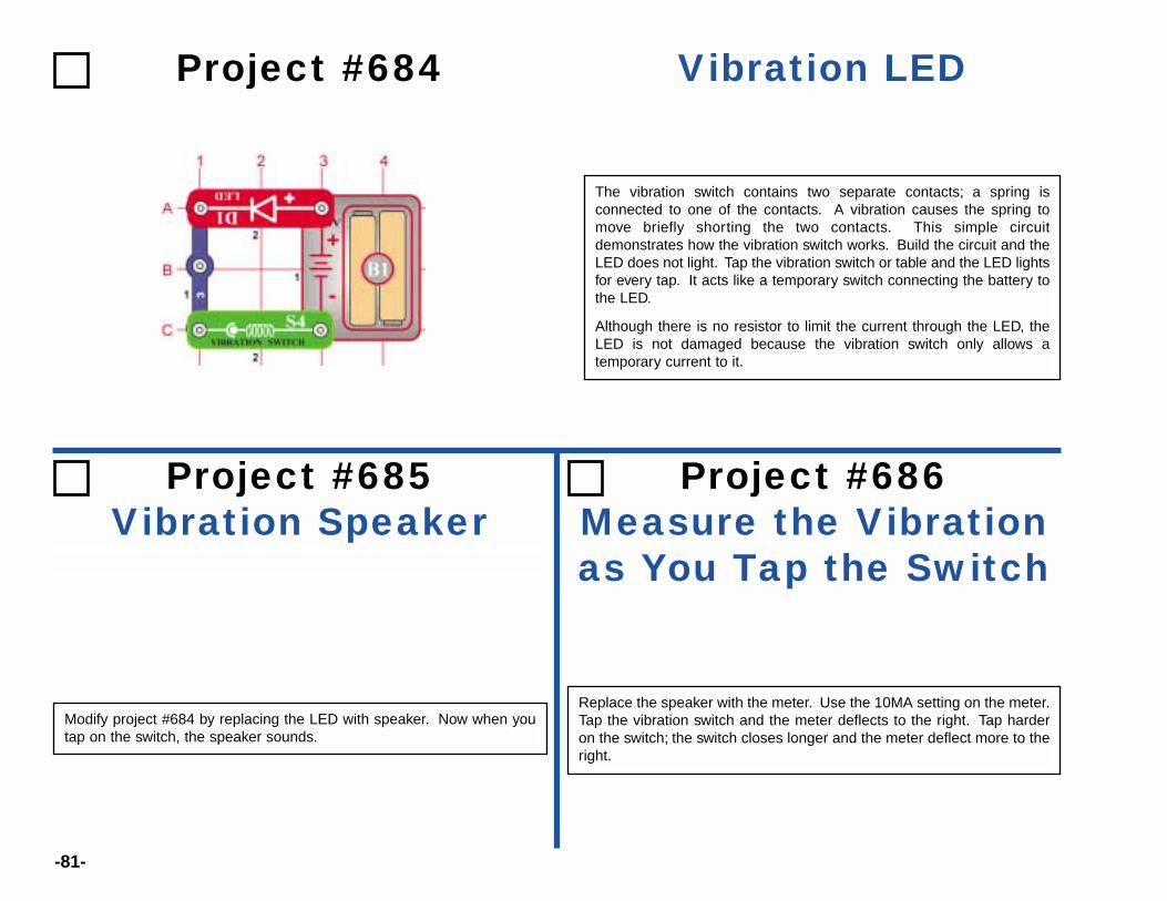
-81-
Project #684 Vibration LED
The vibration switch contains two separate contacts; a spring isconnected to one of the contacts. A vibration causes the spring tomove briefly shorting the two contacts. This simple circuitdemonstrates how the vibration switch works. Build the circuit and theLED does not light. Tap the vibration switch or table and the LED lightsfor every tap. It acts like a temporary switch connecting the battery tothe LED.
Although there is no resistor to limit the current through the LED, theLED is not damaged because the vibration switch only allows atemporary current to it.
Project #685Vibration Speaker
Project #686Measure the Vibrationas You Tap the Switch
Modify project #684 by replacing the LED with speaker. Now when youtap on the switch, the speaker sounds.
Replace the speaker with the meter. Use the 10MA setting on the meter.Tap the vibration switch and the meter deflects to the right. Tap harderon the switch; the switch closes longer and the meter deflect more to theright.

-82-
Project #687OBJECTIVE: To turn the music IC on and off using the
Shaky Birthday Song
Connect the vibration switch to the circuit using the red and blackjumpers. Hold the vibration switch steady in your hand and the musicshould not play. Now move your hand, the music should briefly play. Ifyou continuously shake the switch, the music keeps playing. Turnswitch S1 on and the music plays. Change the sound by shaking thevibration switch.
Project #688 Vibration DirectionConnect the vibration switch to the circuit using the black and red jumperwires. Place the switch horizontally on the table. Rapidly move the switchfrom left to right and notice that the LED does not light. There is not
enough force to expand the internal spring to close the switch. Now movethe switch up and down and see that the LED easily lights. It requiresless force to move the spring back and force.
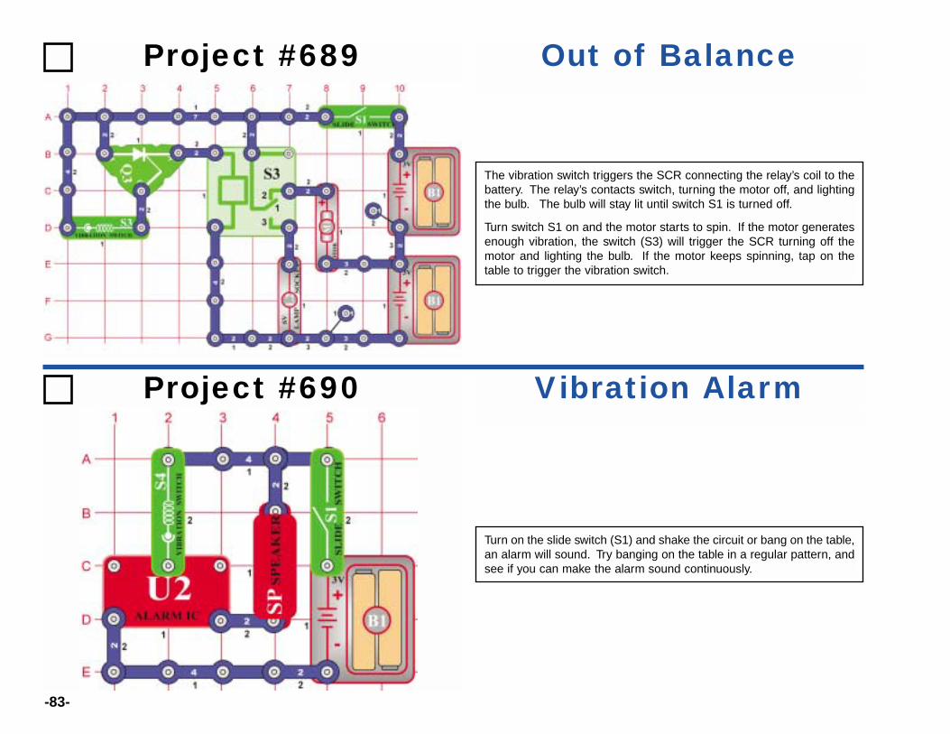
-83-
Project #689 Out of Balance
The vibration switch triggers the SCR connecting the relay’s coil to thebattery. The relay’s contacts switch, turning the motor off, and lightingthe bulb. The bulb will stay lit until switch S1 is turned off.
Turn switch S1 on and the motor starts to spin. If the motor generatesenough vibration, the switch (S3) will trigger the SCR turning off themotor and lighting the bulb. If the motor keeps spinning, tap on thetable to trigger the vibration switch.
Project #690 Vibration Alarm
Turn on the slide switch (S1) and shake the circuit or bang on the table,an alarm will sound. Try banging on the table in a regular pattern, andsee if you can make the alarm sound continuously.
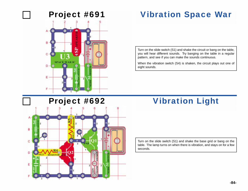
-84-
Project #691 Vibration Space War
Turn on the slide switch (S1) and shake the circuit or bang on the table,you will hear different sounds. Try banging on the table in a regularpattern, and see if you can make the sounds continuous.
When the vibration switch (S4) is shaken, the circuit plays out one ofeight sounds.
Project #692 Vibration Light
Turn on the slide switch (S1) and shake the base grid or bang on thetable. The lamp turns on when there is vibration, and stays on for a fewseconds.

ElencoTM Electronics, Inc.150 W. Carpenter Avenue
Wheeling, IL 60090(847) 541-3800
http://www.elenco.come-mail: [email protected]
Order from www.discoverthis.com Tollfree 866 438 8697