
Oracle Fusion Middleware Connectivity and Knowledge Modules ...
310
Oracle® Fusion Middleware Connectivity and Knowledge Modules Guide for Oracle Data Integrator 12c (12.1.2) E39362-03 January 2014
Transcript of Oracle Fusion Middleware Connectivity and Knowledge Modules ...
Oracle® Fusion MiddlewareConnectivity and Knowledge Modules Guide for Oracle Data Integrator
12c (12.1.2)
E39362-03
January 2014

Oracle Fusion Middleware Connectivity and Knowledge Modules Guide for Oracle Data Integrator, 12c (12.1.2)
E39362-03
Copyright © 2010, 2014, Oracle and/or its affiliates. All rights reserved.
Primary Author: Laura Hofman Miquel
This software and related documentation are provided under a license agreement containing restrictions on use and disclosure and are protected by intellectual property laws. Except as expressly permitted in your license agreement or allowed by law, you may not use, copy, reproduce, translate, broadcast, modify, license, transmit, distribute, exhibit, perform, publish, or display any part, in any form, or by any means. Reverse engineering, disassembly, or decompilation of this software, unless required by law for interoperability, is prohibited.
The information contained herein is subject to change without notice and is not warranted to be error-free. If you find any errors, please report them to us in writing.
If this is software or related documentation that is delivered to the U.S. Government or anyone licensing it on behalf of the U.S. Government, the following notice is applicable:
U.S. GOVERNMENT END USERS: Oracle programs, including any operating system, integrated software, any programs installed on the hardware, and/or documentation, delivered to U.S. Government end users are "commercial computer software" pursuant to the applicable Federal Acquisition Regulation and agency-specific supplemental regulations. As such, use, duplication, disclosure, modification, and adaptation of the programs, including any operating system, integrated software, any programs installed on the hardware, and/or documentation, shall be subject to license terms and license restrictions applicable to the programs. No other rights are granted to the U.S. Government.
This software or hardware is developed for general use in a variety of information management applications. It is not developed or intended for use in any inherently dangerous applications, including applications that may create a risk of personal injury. If you use this software or hardware in dangerous applications, then you shall be responsible to take all appropriate failsafe, backup, redundancy, and other measures to ensure its safe use. Oracle Corporation and its affiliates disclaim any liability for any damages caused by use of this software or hardware in dangerous applications.
Oracle and Java are registered trademarks of Oracle and/or its affiliates. Other names may be trademarks of their respective owners.
Intel and Intel Xeon are trademarks or registered trademarks of Intel Corporation. All SPARC trademarks are used under license and are trademarks or registered trademarks of SPARC International, Inc. AMD, Opteron, the AMD logo, and the AMD Opteron logo are trademarks or registered trademarks of Advanced Micro Devices. UNIX is a registered trademark of The Open Group.
This software or hardware and documentation may provide access to or information on content, products, and services from third parties. Oracle Corporation and its affiliates are not responsible for and expressly disclaim all warranties of any kind with respect to third-party content, products, and services. Oracle Corporation and its affiliates will not be responsible for any loss, costs, or damages incurred due to your access to or use of third-party content, products, or services.

iii
Contents
Preface ............................................................................................................................................................... xv
Audience..................................................................................................................................................... xvDocumentation Accessibility ................................................................................................................... xvRelated Documents ................................................................................................................................... xvConventions ............................................................................................................................................... xvi
1 Introduction
1.1 Terminology................................................................................................................................. 1-11.2 Using This Guide ........................................................................................................................ 1-2
Part I Databases, Files, and XML
2 Oracle Database
2.1 Introduction ................................................................................................................................. 2-12.1.1 Concepts................................................................................................................................ 2-12.1.2 Knowledge Modules ........................................................................................................... 2-12.2 Installation and Configuration.................................................................................................. 2-32.2.1 System Requirements and Certifications ......................................................................... 2-32.2.2 Technology Specific Requirements ................................................................................... 2-42.2.3 Connectivity Requirements................................................................................................ 2-52.3 Setting up the Topology............................................................................................................. 2-62.3.1 Creating an Oracle Data Server ......................................................................................... 2-62.3.2 Creating an Oracle Physical Schema................................................................................. 2-72.4 Setting Up an Integration Project ............................................................................................. 2-72.5 Creating and Reverse-Engineering an Oracle Model ............................................................ 2-72.5.1 Create an Oracle Model ...................................................................................................... 2-72.5.2 Reverse-engineer an Oracle Model ................................................................................... 2-72.6 Setting up Changed Data Capture ........................................................................................... 2-82.7 Setting up Data Quality ............................................................................................................. 2-92.8 Designing a Mapping .............................................................................................................. 2-102.8.1 Loading Data from and to Oracle................................................................................... 2-102.8.2 Integrating Data in Oracle ............................................................................................... 2-112.8.3 Designing an ETL-Style Mapping .................................................................................. 2-122.9 Troubleshooting ....................................................................................................................... 2-162.9.1 Troubleshooting Oracle Database Errors ...................................................................... 2-16
iv
2.9.2 Common Problems and Solutions.................................................................................. 2-16
3 Files
3.1 Introduction ................................................................................................................................. 3-13.1.1 Concepts................................................................................................................................ 3-13.1.2 Knowledge Modules ........................................................................................................... 3-13.2 Installation and Configuration.................................................................................................. 3-23.2.1 System Requirements and Certifications ......................................................................... 3-23.2.2 Technology Specific Requirements ................................................................................... 3-23.2.3 Connectivity Requirements................................................................................................ 3-33.3 Setting up the Topology............................................................................................................. 3-33.3.1 Creating a File Data Server................................................................................................. 3-33.3.2 Creating a File Physical Schema ........................................................................................ 3-43.4 Setting Up an Integration Project ............................................................................................. 3-43.5 Creating and Reverse-Engineering a File Model ................................................................... 3-53.5.1 Create a File Model.............................................................................................................. 3-53.5.2 Reverse-engineer a File Model........................................................................................... 3-53.6 Designing a Mapping ................................................................................................................. 3-93.6.1 Loading Data From Files .................................................................................................... 3-93.6.2 Integrating Data in Files .................................................................................................. 3-11
4 Generic SQL
4.1 Introduction ................................................................................................................................. 4-14.1.1 Concepts................................................................................................................................ 4-14.1.2 Knowledge Modules ........................................................................................................... 4-24.2 Installation and Configuration.................................................................................................. 4-54.2.1 System Requirements and Certifications ......................................................................... 4-54.2.2 Technology-Specific Requirements................................................................................... 4-54.2.3 Connectivity Requirements................................................................................................ 4-54.3 Setting up the Topology............................................................................................................. 4-54.3.1 Creating a Data Server ........................................................................................................ 4-64.3.2 Creating a Physical Schema ............................................................................................... 4-64.4 Setting up an Integration Project .............................................................................................. 4-64.5 Creating and Reverse-Engineering a Model ........................................................................... 4-64.5.1 Create a Data Model............................................................................................................ 4-64.5.2 Reverse-engineer a Data Model......................................................................................... 4-64.6 Setting up Changed Data Capture ........................................................................................... 4-74.7 Setting up Data Quality.............................................................................................................. 4-74.8 Designing a Mapping ................................................................................................................ 4-74.8.1 Loading Data From and to an ANSI SQL-92 Compliant Technology ......................... 4-74.8.2 Integrating Data in an ANSI SQL-92 Compliant Technology....................................... 4-94.8.3 Designing an ETL-Style Mapping ..................................................................................... 4-9
5 XML Files
5.1 Introduction ................................................................................................................................. 5-15.1.1 Concepts................................................................................................................................ 5-1

v
5.1.2 Knowledge Modules ........................................................................................................... 5-25.2 Installation and Configuration.................................................................................................. 5-25.2.1 System Requirements.......................................................................................................... 5-25.2.2 Technologic Specific Requirements .................................................................................. 5-25.2.3 Connectivity Requirements................................................................................................ 5-25.3 Setting up the Topology............................................................................................................. 5-25.3.1 Creating an XML Data Server ............................................................................................ 5-35.3.2 Creating a Physical Schema for XML ............................................................................... 5-45.4 Setting Up an Integration Project ............................................................................................. 5-45.5 Creating and Reverse-Engineering a XML File ...................................................................... 5-45.5.1 Create an XML Model ......................................................................................................... 5-45.5.2 Reverse-Engineering an XML Model................................................................................ 5-55.6 Designing a Mapping ................................................................................................................. 5-55.6.1 Notes about XML Mappings.............................................................................................. 5-55.6.2 Loading Data from and to XML ........................................................................................ 5-65.6.3 Integrating Data in XML..................................................................................................... 5-75.7 Troubleshooting .......................................................................................................................... 5-85.7.1 Detect the Errors Coming from XML................................................................................ 5-85.7.2 Common Errors.................................................................................................................... 5-8
6 Complex Files
6.1 Introduction ................................................................................................................................. 6-16.1.1 Concepts................................................................................................................................ 6-16.1.2 Knowledge Modules ........................................................................................................... 6-26.2 Installation and Configuration.................................................................................................. 6-26.2.1 System Requirements.......................................................................................................... 6-26.2.2 Technology Specific Requirements ................................................................................... 6-36.2.3 Connectivity Requirements................................................................................................ 6-36.3 Setting up the Topology............................................................................................................. 6-36.3.1 Creating a Complex File Data Server................................................................................ 6-36.3.2 Creating a Complex File Physical Schema....................................................................... 6-46.4 Setting Up an Integration Project ............................................................................................. 6-46.5 Creating and Reverse-Engineering a Complex File Model .................................................. 6-56.5.1 Create a Complex File Model............................................................................................. 6-56.5.2 Reverse-engineer a Complex File Model.......................................................................... 6-56.6 Designing a Mapping ................................................................................................................. 6-5
7 Microsoft SQL Server
7.1 Introduction ................................................................................................................................. 7-17.1.1 Concepts................................................................................................................................ 7-17.1.2 Knowledge Modules ........................................................................................................... 7-17.2 Installation and Configuration.................................................................................................. 7-27.2.1 System Requirements and Certifications ......................................................................... 7-27.2.2 Technology Specific Requirements ................................................................................... 7-37.2.3 Connectivity Requirements................................................................................................ 7-47.3 Setting up the Topology............................................................................................................. 7-4

vi
7.3.1 Creating a Microsoft SQL Server Data Server ................................................................. 7-47.3.2 Creating a Microsoft SQL Server Physical Schema ........................................................ 7-57.4 Setting Up an Integration Project ............................................................................................. 7-57.5 Creating and Reverse-Engineering a Microsoft SQL Server Model .................................... 7-57.5.1 Create a Microsoft SQL Server Model .............................................................................. 7-57.5.2 Reverse-engineer a Microsoft SQL Server Model ........................................................... 7-67.6 Setting up Changed Data Capture ........................................................................................... 7-67.7 Setting up Data Quality.............................................................................................................. 7-77.8 Designing a Mapping ................................................................................................................. 7-77.8.1 Loading Data from and to Microsoft SQL Server ........................................................... 7-77.8.2 Integrating Data in Microsoft SQL Server........................................................................ 7-9
8 Microsoft Excel
8.1 Introduction ................................................................................................................................. 8-18.1.1 Concepts................................................................................................................................ 8-18.1.2 Knowledge Modules ........................................................................................................... 8-18.2 Installation and Configuration.................................................................................................. 8-28.2.1 System Requirements and Certifications ......................................................................... 8-28.2.2 Technology Specific Requirements ................................................................................... 8-28.2.3 Connectivity Requirements................................................................................................ 8-28.3 Setting up the Topology............................................................................................................. 8-38.3.1 Creating a Microsoft Excel Data Server............................................................................ 8-38.3.2 Creating a Microsoft Excel Physical Schema ................................................................... 8-38.4 Setting Up an Integration Project ............................................................................................. 8-48.5 Creating and Reverse-Engineering a Microsoft Excel Model............................................... 8-48.5.1 Create a Microsoft Excel Model......................................................................................... 8-48.5.2 Reverse-engineer a Microsoft Excel Model...................................................................... 8-48.6 Designing a Mapping ................................................................................................................. 8-58.6.1 Loading Data From and to Microsoft Excel ..................................................................... 8-58.6.2 Integrating Data in Microsoft Excel .................................................................................. 8-58.7 Troubleshooting .......................................................................................................................... 8-68.7.1 Decoding Error Messages................................................................................................... 8-68.7.2 Common Problems and Solutions..................................................................................... 8-6
9 Netezza
9.1 Introduction ................................................................................................................................. 9-19.1.1 Concepts................................................................................................................................ 9-19.1.2 Knowledge Modules ........................................................................................................... 9-19.2 Installation and Configuration.................................................................................................. 9-29.2.1 System Requirements and Certifications ......................................................................... 9-29.2.2 Technology Specific Requirements ................................................................................... 9-29.2.3 Connectivity Requirements................................................................................................ 9-39.3 Setting up the Topology............................................................................................................. 9-39.3.1 Creating a Netezza Data Server......................................................................................... 9-39.3.2 Creating a Netezza Physical Schema ................................................................................ 9-39.4 Setting Up an Integration Project ............................................................................................. 9-49.5 Creating and Reverse-Engineering a Netezza Model ........................................................... 9-4

vii
9.5.1 Create a Netezza Model...................................................................................................... 9-49.5.2 Reverse-engineer a Netezza Model................................................................................... 9-49.6 Setting up Data Quality ............................................................................................................. 9-59.7 Designing a Mapping ................................................................................................................. 9-59.7.1 Loading Data from and to Netezza................................................................................... 9-59.7.2 Integrating Data in Netezza ............................................................................................... 9-6
10 Teradata
10.1 Introduction .............................................................................................................................. 10-110.1.1 Concepts............................................................................................................................. 10-110.1.2 Knowledge Modules ........................................................................................................ 10-110.2 Installation and Configuration............................................................................................... 10-210.2.1 System Requirements and Certifications ...................................................................... 10-210.2.2 Technology Specific Requirements ................................................................................ 10-310.2.3 Connectivity Requirements............................................................................................. 10-310.3 Setting up the Topology.......................................................................................................... 10-310.3.1 Creating a Teradata Data Server .................................................................................... 10-410.3.2 Creating a Teradata Physical Schema............................................................................ 10-410.4 Setting Up an Integration Project .......................................................................................... 10-410.5 Creating and Reverse-Engineering a Teradata Model ....................................................... 10-510.5.1 Create a Teradata Model.................................................................................................. 10-510.5.2 Reverse-engineer a Teradata Model .............................................................................. 10-510.6 Setting up Data Quality .......................................................................................................... 10-610.7 Designing a Mapping .............................................................................................................. 10-610.7.1 Loading Data from and to Teradata .............................................................................. 10-610.7.2 Integrating Data in Teradata ........................................................................................... 10-810.7.3 Designing an ETL-Style Mapping ................................................................................ 10-1210.8 KM Optimizations for Teradata........................................................................................... 10-1510.8.1 Primary Indexes and Statistics...................................................................................... 10-1510.8.2 Support for Teradata Utilities ....................................................................................... 10-1610.8.3 Support for Named Pipes .............................................................................................. 10-1610.8.4 Optimized Management of Temporary Tables ......................................................... 10-17
11 IBM DB2 for iSeries
11.1 Introduction .............................................................................................................................. 11-111.1.1 Concepts............................................................................................................................. 11-111.1.2 Knowledge Modules ........................................................................................................ 11-111.2 Installation and Configuration............................................................................................... 11-211.2.1 System Requirements and Certifications ...................................................................... 11-211.2.2 Technology Specific Requirements ................................................................................ 11-311.2.3 Connectivity Requirements............................................................................................. 11-311.3 Setting up the Topology.......................................................................................................... 11-311.3.1 Creating a DB2/400 Data Server .................................................................................... 11-311.3.2 Creating a DB2/400 Physical Schema............................................................................ 11-411.4 Setting Up an Integration Project .......................................................................................... 11-411.5 Creating and Reverse-Engineering an IBM DB2/400 Model ............................................ 11-4

viii
11.5.1 Create an IBM DB2/400 Model ...................................................................................... 11-511.5.2 Reverse-engineer an IBM DB2/400 Model ................................................................... 11-511.6 Setting up Changed Data Capture ........................................................................................ 11-511.6.1 Setting up Trigger-Based CDC ....................................................................................... 11-511.6.2 Setting up Log-Based CDC.............................................................................................. 11-611.7 Setting up Data Quality........................................................................................................... 11-911.8 Designing a Mapping .............................................................................................................. 11-911.8.1 Loading Data from and to IBM DB2 for iSeries ........................................................ 11-1011.8.2 Integrating Data in IBM DB2 for iSeries ..................................................................... 11-1111.9 Specific Considerations with DB2 for iSeries..................................................................... 11-1111.9.1 Installing the Run-Time Agent on iSeries ................................................................... 11-1111.9.2 Alternative Connectivity Methods for iSeries ............................................................ 11-1111.10 Troubleshooting ..................................................................................................................... 11-1211.10.1 Troubleshooting Error messages.................................................................................. 11-1211.10.2 Common Problems and Solutions................................................................................ 11-13
12 IBM DB2 UDB
12.1 Introduction .............................................................................................................................. 12-112.2 Concepts .................................................................................................................................... 12-112.3 Knowledge Modules ............................................................................................................... 12-112.4 Specific Requirements ............................................................................................................. 12-3
Part II Business Intelligence
13 Oracle Business Intelligence Enterprise Edition
13.1 Introduction .............................................................................................................................. 13-113.1.1 Concepts............................................................................................................................. 13-113.1.2 Knowledge Modules ........................................................................................................ 13-113.2 Installation and Configuration............................................................................................... 13-213.2.1 System Requirements and Certifications ...................................................................... 13-213.2.2 Technology Specific Requirements ................................................................................ 13-213.2.3 Connectivity Requirements............................................................................................. 13-213.3 Setting up the Topology.......................................................................................................... 13-213.3.1 Creating an Oracle BI Data Server ................................................................................. 13-313.3.2 Creating an Oracle BI Physical Schema......................................................................... 13-313.4 Setting Up an Integration Project .......................................................................................... 13-413.5 Creating and Reverse-Engineering an Oracle BI Model .................................................... 13-413.5.1 Create an Oracle BI Model............................................................................................... 13-413.5.2 Reverse-engineer an Oracle BI Model ........................................................................... 13-413.6 Setting up Data Quality........................................................................................................... 13-413.7 Designing a Mapping .............................................................................................................. 13-513.7.1 Loading Data from and to Oracle BI.............................................................................. 13-513.7.2 Integrating Data in Oracle BI .......................................................................................... 13-5
14 Oracle Business Intelligence Enterprise Edition Data Lineage
14.1 Introduction .............................................................................................................................. 14-1

ix
14.1.1 Components....................................................................................................................... 14-114.1.2 Lineage Lifecycle............................................................................................................... 14-214.2 Installing the Lineage in an OBIEE Server ........................................................................... 14-314.2.1 Installation Overview....................................................................................................... 14-314.2.2 Requirements..................................................................................................................... 14-414.2.3 Installation Instructions ................................................................................................... 14-514.2.4 Post-Installation Tasks ..................................................................................................... 14-614.3 Exporting Metadata from OBIEE and Refreshing the OBIEE Lineage ............................ 14-814.4 Refreshing the OBIEE Lineage from Existing Exports ..................................................... 14-1114.4.1 Exporting the OBIEE Repository Documentation to a Text File ............................. 14-1214.4.2 Exporting the OBIEE Web Catalog Report to a Text File.......................................... 14-1214.4.3 Refreshing the OBIEE Lineage From Existing Exports ............................................. 14-1214.5 Automating the Lineage Tasks ............................................................................................ 14-1414.5.1 Configuring the Scripts .................................................................................................. 14-1514.5.2 Automating Lineage Deployment................................................................................ 14-1714.5.3 Automating Lineage Refresh ........................................................................................ 14-1814.6 Using the Lineage in OBIEE Dashboards........................................................................... 14-1914.6.1 Viewing Execution Statistics ......................................................................................... 14-1914.6.2 Viewing and Filtering Lineage Data ............................................................................ 14-1914.6.3 Using the Dashboard...................................................................................................... 14-2014.6.4 Using Lineage and Hierarchy ....................................................................................... 14-2014.6.5 Using Contextual Lineage ............................................................................................. 14-22
Part III Other Technologies
15 JMS
15.1 Introduction .............................................................................................................................. 15-115.1.1 Concepts............................................................................................................................. 15-115.1.2 Knowledge Modules ........................................................................................................ 15-315.2 Installation and Configuration............................................................................................... 15-315.2.1 System Requirements and Certifications ...................................................................... 15-415.2.2 Technology Specific Requirements ................................................................................ 15-415.2.3 Connectivity Requirements............................................................................................. 15-415.3 Setting up the Topology.......................................................................................................... 15-415.3.1 Creating a JMS Data Server ............................................................................................. 15-415.3.2 Creating a JMS Physical Schema .................................................................................... 15-515.4 Setting Up an Integration Project .......................................................................................... 15-515.5 Creating and Defining a JMS Model ..................................................................................... 15-515.5.1 Create a JMS Model .......................................................................................................... 15-515.5.2 Defining the JMS Datastores ........................................................................................... 15-615.6 Designing a Mapping .............................................................................................................. 15-715.6.1 Loading Data from a JMS Source ................................................................................... 15-715.6.2 Integrating Data in a JMS Target .................................................................................... 15-715.7 JMS Standard Properties ......................................................................................................... 15-915.7.1 Using JMS Properties ..................................................................................................... 15-10

x
16 JMS XML
16.1 Introduction .............................................................................................................................. 16-116.1.1 Concepts............................................................................................................................. 16-116.1.2 Knowledge Modules ........................................................................................................ 16-316.2 Installation and Configuration............................................................................................... 16-316.2.1 System Requirements and Certifications ...................................................................... 16-316.2.2 Technology Specific Requirements ................................................................................ 16-316.2.3 Connectivity Requirements............................................................................................. 16-316.3 Setting up the Topology.......................................................................................................... 16-416.3.1 Creating a JMS XML Data Server ................................................................................... 16-416.3.2 Creating a JMS XML Physical Schema .......................................................................... 16-616.4 Setting Up an Integration Project .......................................................................................... 16-616.5 Creating and Reverse-Engineering a JMS XML Model...................................................... 16-616.5.1 Create a JMS XML Model ................................................................................................ 16-616.5.2 Reverse-Engineering a JMS XML Model....................................................................... 16-616.6 Designing a Mapping .............................................................................................................. 16-716.6.1 Loading Data from a JMS XML Source ......................................................................... 16-716.6.2 Integrating Data in a JMS XML Target .......................................................................... 16-7
17 LDAP Directories
17.1 Introduction .............................................................................................................................. 17-117.1.1 Concepts............................................................................................................................. 17-117.1.2 Knowledge Modules ........................................................................................................ 17-117.2 Installation and Configuration............................................................................................... 17-217.2.1 System Requirements....................................................................................................... 17-217.2.2 Technologic Specific Requirements ............................................................................... 17-217.2.3 Connectivity Requirements............................................................................................. 17-217.3 Setting up the Topology.......................................................................................................... 17-217.3.1 Creating an LDAP Data Server....................................................................................... 17-317.3.2 Creating a Physical Schema for LDAP .......................................................................... 17-417.4 Setting Up an Integration Project .......................................................................................... 17-417.5 Creating and Reverse-Engineering an LDAP Directory .................................................... 17-417.5.1 Create an LDAP Model.................................................................................................... 17-417.5.2 Reverse-Engineering an LDAP Model .......................................................................... 17-417.6 Designing a Mapping .............................................................................................................. 17-517.6.1 Loading Data from and to LDAP ................................................................................... 17-517.6.2 Integrating Data in an LDAP Directory ........................................................................ 17-617.7 Troubleshooting ....................................................................................................................... 17-6
18 Oracle TimesTen In-Memory Database
18.1 Introduction .............................................................................................................................. 18-118.1.1 Concepts............................................................................................................................. 18-118.1.2 Knowledge Modules ........................................................................................................ 18-218.2 Installation and Configuration............................................................................................... 18-218.2.1 System Requirements and Certifications ...................................................................... 18-218.2.2 Technology Specific Requirements ................................................................................ 18-2

xi
18.2.3 Connectivity Requirements............................................................................................. 18-318.3 Setting up the Topology.......................................................................................................... 18-318.3.1 Creating a TimesTen Data Server................................................................................... 18-318.3.2 Creating a TimesTen Physical Schema .......................................................................... 18-418.4 Setting Up an Integration Project .......................................................................................... 18-418.5 Creating and Reverse-Engineering a TimesTen Model ..................................................... 18-418.5.1 Create a TimesTen Model................................................................................................ 18-418.5.2 Reverse-engineer a TimesTen Model............................................................................. 18-518.6 Setting up Data Quality .......................................................................................................... 18-518.7 Designing a Mapping .............................................................................................................. 18-518.7.1 Loading Data from and to TimesTen............................................................................. 18-518.7.2 Integrating Data in TimesTen ......................................................................................... 18-6
19 Oracle Changed Data Capture Adapters
19.1 Introduction .............................................................................................................................. 19-119.1.1 Concepts............................................................................................................................. 19-119.1.2 Knowledge Modules ........................................................................................................ 19-219.2 Installation and Configuration............................................................................................... 19-219.2.1 System Requirements....................................................................................................... 19-219.2.2 Technology Specific Requirements ................................................................................ 19-219.2.3 Connectivity Requirements............................................................................................. 19-319.3 Setting up the Topology.......................................................................................................... 19-319.3.1 Creating an Attunity Stream Data Server ..................................................................... 19-319.3.2 Creating an Attunity Stream Physical Schema............................................................. 19-419.4 Setting Up an Integration Project .......................................................................................... 19-419.5 Creating and Reverse-Engineering an Attunity Stream Model ........................................ 19-419.5.1 Create an Attunity Stream Model .................................................................................. 19-419.5.2 Reverse-engineer an Attunity Stream Model ............................................................... 19-419.6 Designing a Mapping Using the LKM Attunity to SQL .................................................... 19-5
20 Oracle GoldenGate
20.1 Introduction .............................................................................................................................. 20-120.1.1 Overview of the GoldeGate CDC Process..................................................................... 20-120.1.2 Knowledge Modules ........................................................................................................ 20-220.2 Installation and Configuration............................................................................................... 20-320.2.1 System Requirements and Certifications ...................................................................... 20-320.2.2 Technology Specific Requirements ................................................................................ 20-420.2.3 Connectivity Requirements............................................................................................. 20-420.3 Working with the Oracle GoldenGate JKMs ....................................................................... 20-420.3.1 Define the Topology......................................................................................................... 20-420.3.2 Create the Replicated Tables ........................................................................................... 20-820.3.3 Set Up an Integration Project .......................................................................................... 20-820.3.4 Configure CDC for the Source Datastores .................................................................... 20-920.3.5 Configure and Start Oracle GoldenGate Processes (Offline mode only) ............... 20-1120.3.6 Design Mappings Using Replicated Data ................................................................... 20-1220.4 Advanced Configuration ...................................................................................................... 20-12

xii
20.4.1 Initial Load Method........................................................................................................ 20-1220.4.2 Tuning Replication Performances ................................................................................ 20-1220.4.3 One Source Multiple Staging Configuration (Offline mode only) .......................... 20-13
21 Oracle SOA Suite Cross References
21.1 Introduction .............................................................................................................................. 21-121.1.1 Concepts............................................................................................................................. 21-121.1.2 Knowledge Modules ........................................................................................................ 21-321.1.3 Overview of the SOA XREF KM Process ...................................................................... 21-421.2 Installation and Configuration............................................................................................... 21-521.2.1 System Requirements and Certifications ...................................................................... 21-621.2.2 Technology Specific Requirements ................................................................................ 21-621.2.3 Connectivity Requirements............................................................................................. 21-621.3 Working with XREF using the SOA Cross References KMs ............................................. 21-621.3.1 Defining the Topology ..................................................................................................... 21-621.3.2 Setting up the Project ....................................................................................................... 21-721.3.3 Designing a Mapping with the Cross-References KMs .............................................. 21-721.4 Knowledge Module Options Reference................................................................................ 21-8
Part IV Appendices
A Oracle Data Integrator Driver for LDAP Reference
A.1 Introduction to Oracle Data Integrator Driver for LDAP .................................................... A-1A.2 LDAP Processing Overview..................................................................................................... A-1A.2.1 LDAP to Relational Mapping............................................................................................ A-2A.2.2 Managing Relational Schemas .......................................................................................... A-5A.3 Installation and Configuration ................................................................................................ A-6A.3.1 Driver Configuration.......................................................................................................... A-6A.3.2 Using an External Database to Store the Data.............................................................. A-12A.3.3 LDAP Directory Connection Configuration ................................................................. A-14A.3.4 Table Aliases Configuration............................................................................................ A-15A.4 SQL Syntax................................................................................................................................ A-16A.4.1 SQL Statements ................................................................................................................. A-17A.4.2 SQL FUNCTIONS............................................................................................................. A-19A.5 JDBC API Implemented Features .......................................................................................... A-22
B Oracle Data Integrator Driver for XML Reference
B.1 Introduction to Oracle Data Integrator Driver for XML ...................................................... B-1B.2 XML Processing Overview ....................................................................................................... B-2B.2.1 XML to SQL Mapping........................................................................................................ B-2B.2.2 XML Namespaces ............................................................................................................... B-3B.2.3 Managing Schemas............................................................................................................. B-3B.2.4 Locking................................................................................................................................. B-5B.2.5 XML Schema (XSD) Support............................................................................................. B-5B.3 Installation and Configuration................................................................................................. B-5B.3.1 Driver Configuration.......................................................................................................... B-5
xiii
B.3.2 Automatically Create Multiple Schemas....................................................................... B-11B.3.3 Using an External Database to Store the Data.............................................................. B-11B.4 Detailed Driver Commands ................................................................................................... B-16B.4.1 CREATE FILE.................................................................................................................... B-17B.4.2 CREATE FOREIGNKEYS ................................................................................................ B-18B.4.3 CREATE XMLFILE........................................................................................................... B-18B.4.4 CREATE SCHEMA........................................................................................................... B-19B.4.5 DROP FOREIGNKEYS..................................................................................................... B-20B.4.6 DROP SCHEMA ............................................................................................................... B-20B.4.7 LOAD FILE ........................................................................................................................ B-20B.4.8 SET SCHEMA.................................................................................................................... B-21B.4.9 SYNCHRONIZE ............................................................................................................... B-21B.4.10 UNLOCK FILE .................................................................................................................. B-22B.4.11 TRUNCATE SCHEMA .................................................................................................... B-22B.4.12 VALIDATE ........................................................................................................................ B-22B.4.13 WRITE MAPPING FILE .................................................................................................. B-23B.5 SQL Syntax................................................................................................................................ B-24B.5.1 SQL Statements ................................................................................................................. B-24B.5.2 SQL FUNCTIONS............................................................................................................. B-27B.6 JDBC API Implemented Features .......................................................................................... B-30B.7 XML Schema Supported Features ......................................................................................... B-31B.7.1 Datatypes ........................................................................................................................... B-31B.7.2 Supported Elements ......................................................................................................... B-31B.7.3 Unsupported Features ..................................................................................................... B-37
C Oracle Data Integrator Driver for Complex Files Reference
C.1 Introduction to Oracle Data Integrator Driver for Complex Files ...................................... C-1C.2 Complex Files Processing Overview....................................................................................... C-1C.2.1 Generating the Native Schema ......................................................................................... C-2C.2.2 XML to SQL Mapping........................................................................................................ C-2C.2.3 Supported Features ............................................................................................................ C-2C.3 Driver Configuration................................................................................................................. C-3C.4 Detailed Driver Commands ..................................................................................................... C-5C.5 JDBC API and XML Schema Supported Features................................................................. C-6

xiv
xv
Preface
This book describes how work with different technologies in Oracle Data Integrator.
This preface contains the following topics:
■ Audience
■ Documentation Accessibility
■ Related Documents
■ Conventions
AudienceThis document is intended for developers who want to work with Knowledge Modules for their integration processes in Oracle Data Integrator.
Documentation AccessibilityFor information about Oracle's commitment to accessibility, visit the Oracle Accessibility Program website at http://www.oracle.com/pls/topic/lookup?ctx=acc&id=docacc.
Access to Oracle SupportOracle customers have access to electronic support through My Oracle Support. For information, visit http://www.oracle.com/pls/topic/lookup?ctx=acc&id=info or visit http://www.oracle.com/pls/topic/lookup?ctx=acc&id=trs if you are hearing impaired.
Related DocumentsFor more information, see the following Oracle resources:
■ Installing and Configuring Oracle Data Integrator
■ Upgrading Oracle Data Integrator
■ Developer's Guide for Oracle Data Integrator
■ Knowledge Module Developer's Guide for Oracle Data Integrator
■ Application Adapters Guide for Oracle Data Integrator
■ Oracle Data Integrator Studio Help

xvi
■ Release Notes for Oracle Data Integrator
ConventionsThe following text conventions are used in this document:
Convention Meaning
boldface Boldface type indicates graphical user interface elements associated with an action, or terms defined in text or the glossary.
italic Italic type indicates book titles, emphasis, or placeholder variables for which you supply particular values.
monospace Monospace type indicates commands within a paragraph, URLs, code in examples, text that appears on the screen, or text that you enter.

1
Introduction 1-1
1Introduction
This book describes how work with different technologies in Oracle Data Integrator.
This book includes the following parts:
■ Part I, "Databases, Files, and XML"
■ Part II, "Business Intelligence"
■ Part III, "Other Technologies"
Application Adapters are covered in a separate guide. See the Application Adapters Guide for Oracle Data Integrator for more information.
This chapter provides an introduction to the terminology used in the Oracle Data Integrator documentation and describes the basic steps of how to use Knowledge Modules in Oracle Data Integrator.
This chapter contains the following sections:
■ Section 1.1, "Terminology"
■ Section 1.2, "Using This Guide"
1.1 TerminologyThis section defines some common terms that are used in this document and throughout the related documents mentioned in the Preface.
Knowledge ModuleKnowledge Modules (KMs) are components of Oracle Data Integrator that are used to generate the code to perform specific actions against certain technologies.
Combined with a connectivity layer such as, for example, JDBC, JMS, or JCA, Knowledge Modules allow running defined tasks against a technology, such as connecting to this technology, extracting data from it, transforming the data, checking it, integrating it, etc.
Application AdapterOracle Application Adapters for Data Integration provide specific software components for integrating enterprise applications data. Enterprise applications suported by Oracle Data Integrator include Oracle E-Business Suite, Siebel, SAP, etc.
An adapter is a group of Knowledge Modules. In some cases, this group also contains an attached technology definition for Oracle Data Integrator.
Application Adapters are covered in a separate guide. See the Application Adapters Guide for Oracle Data Integrator for more information.

Using This Guide
1-2 Oracle Fusion Middleware Connectivity and Knowledge Modules Guide for Oracle Data Integrator
1.2 Using This GuideThis guide provides conceptual information and processes for working with knowledge modules and technologies supported in Oracle Data Integrator.
Each chapter explains how to configure a given technology, set up a project and use the technology-specific knowledge modules to perform integration operations.
Some knowledge modules are not technology-specific and require a technology that support an industry standard. These knowledge modules are referred to as Generic knowledge modules. For example the knowledge modules listed in Chapter 4, "Generic SQL" and in Chapter 15, "JMS" are designed to work respectively with any ANSI SQL-92 compliant database and any JMS compliant message provider.
When these generic knowledge module can be used with a technology, the technology chapter will mention it. However, we recommend using technology-specific knowledge modules for better performances and enhanced technology-specific feature coverage.
Before using a knowledge module, it is recommended to review the knowledge module description in Oracle Data Integrator Studio for usage details, limitations and requirements. In addition, although knowledge modules options are pre-configured with default values to work out of the box, it is also recommended to review these options and their description.
The chapters in this guide will provide you with the important usage, options, limitation and requirement information attached to the technologies and knowledge modules.

Part IPart I Databases, Files, and XML
This part describes how to work with databases, files, and XML files in Oracle Data Integrator.
Part I contains the following chapters:
■ Chapter 2, "Oracle Database"
■ Chapter 3, "Files"
■ Chapter 4, "Generic SQL"
■ Chapter 5, "XML Files"
■ Chapter 6, "Complex Files"
■ Chapter 7, "Microsoft SQL Server"
■ Chapter 8, "Microsoft Excel"
■ Chapter 9, "Netezza"
■ Chapter 10, "Teradata"
■ Chapter 11, "IBM DB2 for iSeries"
■ Chapter 12, "IBM DB2 UDB"


2
Oracle Database 2-1
2Oracle Database
This chapter describes how to work with Oracle Database in Oracle Data Integrator.
This chapter includes the following sections:
■ Section 2.1, "Introduction"
■ Section 2.2, "Installation and Configuration"
■ Section 2.4, "Setting Up an Integration Project"
■ Section 2.5, "Creating and Reverse-Engineering an Oracle Model"
■ Section 2.6, "Setting up Changed Data Capture"
■ Section 2.7, "Setting up Data Quality"
■ Section 2.8, "Designing a Mapping"
■ Section 2.9, "Troubleshooting"
2.1 IntroductionOracle Data Integrator (ODI) seamlessly integrates data in an Oracle Database. All Oracle Data Integrator features are designed to work best with the Oracle Database engine, including reverse-engineering, changed data capture, data quality, and mappings.
2.1.1 ConceptsThe Oracle Database concepts map the Oracle Data Integrator concepts as follows: An Oracle Instance corresponds to a data server in Oracle Data Integrator. Within this instance, a schema maps to an Oracle Data Integrator physical schema. A set of related objects within one schema corresponds to a data model, and each table, view or synonym will appear as an ODI datastore, with its attributes, columns and constraints.
Oracle Data Integrator uses Java Database Connectivity (JDBC) to connect to Oracle database instance.
2.1.2 Knowledge ModulesOracle Data Integrator provides the Knowledge Modules (KM) listed in Table 2–1 for handling Oracle data. The KMs use Oracle specific features. It is also possible to use the generic SQL KMs with the Oracle Database. See Chapter 4, "Generic SQL" for more information.

Introduction
2-2 Oracle Fusion Middleware Connectivity and Knowledge Modules Guide for Oracle Data Integrator
Table 2–1 Oracle Database Knowledge Modules
Knowledge Module Description
RKM Oracle Reverse-engineers tables, views, columns, primary keys, non unique indexes and foreign keys.
JKM Oracle 11g Consistent (Streams) Creates the journalizing infrastructure for consistent set journalizing on Oracle 11g tables, using Oracle Streams.
JKM Oracle Consistent Creates the journalizing infrastructure for consistent set journalizing on Oracle tables using triggers.
JKM Oracle Consistent (Update Date) Creates the journalizing infrastructure for consistent set journalizing on Oracle tables using triggers based on a Last Update Date column on the source tables.
JKM Oracle Simple Creates the journalizing infrastructure for simple journalizing on Oracle tables using triggers.
JKM Oracle to Oracle Consistent (OGG Online)
Creates and manages the ODI CDC framework infrastructure when using Oracle GoldenGate for CDC. See Chapter 20, "Oracle GoldenGate" for more information.
CKM Oracle Checks data integrity against constraints defined on an Oracle table.
LKM File to Oracle (EXTERNAL TABLE) Loads data from a file to an Oracle staging area using the EXTERNAL TABLE SQL Command.
LKM File to Oracle (SQLLDR) Loads data from a file to an Oracle staging area using the SQL*Loader command line utility.
LKM MSSQL to Oracle (BCP SQLLDR) Loads data from a Microsoft SQL Server to Oracle database (staging area) using the BCP and SQL*Loader utilities.
LKM Oracle BI to Oracle (DBLINK) Loads data from any Oracle BI physical layer to an Oracle target database using database links. See Chapter 13, "Oracle Business Intelligence Enterprise Edition" for more information.
LKM Oracle to Oracle (DBLINK) Loads data from an Oracle source database to an Oracle staging area database using database links.
LKM Oracle to Oracle Pull (DB Link) Loads data from an Oracle source database to an Oracle staging area database using database links. It does not create a view in the source database. It also does not creates the synonym in the staging database. Built-in KM.
LKM Oracle to Oracle Push (DB Link) Loads and integrates data into Oracle target table using database links. It does not create the synonym in the staging database. Any settings in the IKM would be ignored. Built-in KM.
LKM Oracle to Oracle (datapump) Loads data from an Oracle source database to an Oracle staging area database using external tables in the datapump format.
LKM SQL to Oracle Loads data from any ANSI SQL-92 source database to an Oracle staging area.
LKM SAP BW to Oracle (SQLLDR) Loads data from SAP BW systems to an Oracle staging using SQL*Loader utilities. See the Application Adapters Guide for Oracle Data Integrator for more information.
LKM SAP ERP to Oracle (SQLLDR) Loads data from SAP ERP systems to an Oracle staging using SQL*Loader utilities. See the Application Adapters Guide for Oracle Data Integrator for more information.
IKM Oracle Incremental Update Integrates data in an Oracle target table in incremental update mode. Supports Flow Control.
IKM Oracle Incremental Update (MERGE) Integrates data in an Oracle target table in incremental update mode, using a MERGE statement. Supports Flow Control.

Installation and Configuration
Oracle Database 2-3
2.2 Installation and ConfigurationMake sure you have read the information in this section before you start using the Oracle Knowledge Modules:
■ System Requirements and Certifications
■ Technology Specific Requirements
■ Connectivity Requirements
2.2.1 System Requirements and CertificationsBefore performing any installation you should read the system requirements and certification documentation to ensure that your environment meets the minimum installation requirements for the products you are installing.
The list of supported platforms and versions is available on Oracle Technical Network (OTN):
IKM Oracle Incremental Update (PL SQL) Integrates data in an Oracle target table in incremental update mode using PL/SQL. Supports Flow Control.
IKM Oracle Insert Integrates data into an Oracle target table in append mode. The data is loaded directly in the target table with a single INSERT SQL statement. Built-in KM.
IKM Oracle Update Integrates data into an Oracle target table in incremental update mode. The data is loaded directly into the target table with a single UPDATE SQL statement. Built-in KM.
IKM Oracle Merge Integrates data into an Oracle target table in incremental update mode. The data is loaded directly into the target table with a single MERGE SQL statement. Built-in KM.
IKM Oracle Multi-Insert Integrates data from one source into one or many Oracle target tables in append mode, using a multi-table insert statement (MTI). This IKM can be utilized in a single mapping to load multiple targets. Built-in KM.
IKM Oracle Multi Table Insert Integrates data from one source into one or many Oracle target tables in append mode, using a multi-table insert statement (MTI). Supports Flow Control.
IKM Oracle Slowly Changing Dimension Integrates data in an Oracle target table used as a Type II Slowly Changing Dimension. Supports Flow Control.
IKM Oracle Spatial Incremental Update Integrates data into an Oracle (9i or above) target table in incremental update mode using the MERGE DML statement. This module supports the SDO_GEOMETRY datatype. Supports Flow Control.
IKM Oracle to Oracle Control Append (DBLINK)
Integrates data from one Oracle instance into an Oracle target table on another Oracle instance in control append mode. Supports Flow Control.
This IKM is typically used for ETL configurations: source and target tables are on different Oracle instances and the mapping's staging area is set to the logical schema of the source tables or a third schema.
SKM Oracle Generates data access Web services for Oracle databases. See "Working with Data Services" in the Developer's Guide for Oracle Data Integrator for information about how to use this SKM.
Table 2–1 (Cont.) Oracle Database Knowledge Modules
Knowledge Module Description

Installation and Configuration
2-4 Oracle Fusion Middleware Connectivity and Knowledge Modules Guide for Oracle Data Integrator
http://www.oracle.com/technology/products/oracle-data-integrator/index.html.
2.2.2 Technology Specific RequirementsSome of the Knowledge Modules for Oracle use specific features of this database. This section lists the requirements related to these features.
2.2.2.1 Using the SQL*Loader UtilityThis section describes the requirements that must be met before using the SQL*Loader utility with Oracle database.
■ The Oracle Client and the SQL*Loader utility must be installed on the machine running the Oracle Data Integrator Agent.
■ The server names defined in the Topology must match the Oracle TNS name used to access the Oracle instances.
■ A specific log file is created by SQL*Loader. We recommend looking at this file in case of error. Control Files (CTL), Log files (LOG), Discard Files (DSC) and Bad files (BAD) are placed in the work directory defined in the physical schema of the source files.
■ Using the DIRECT mode requires that Oracle Data integrator Agent run on the target Oracle server machine. The source file must also be on that machine.
2.2.2.2 Using External TablesThis section describes the requirements that must be met before using external tables in Oracle database.
■ The file to be loaded by the External Table command needs to be accessible from the Oracle instance. This file must be located on the file system of the server machine or reachable from a Unique Naming Convention path (UNC path) or stored locally.
■ For performance reasons, it is recommended to install the Oracle Data Integrator Agent on the target server machine.
2.2.2.3 Using Oracle StreamsThis section describes the requirements for using Oracle Streams Journalizing knowledge modules.
The following requirements must be met before setting up changed data capture using Oracle Streams:
■ Oracle Streams must be installed on the Oracle Database.
■ The Oracle database must run using a SPFILE (only required for AUTO_CONFIGURATION option).
■ The AQ_TM_PROCESSES option must be either left to the default value, or set to a value different from 0 and 10.
Note: It is recommended to review first the "Changed Data Capture" chapter in the Oracle Database Data Warehousing Guide, which contains the comprehensive list of requirements for Oracle Streams.

Installation and Configuration
Oracle Database 2-5
■ The COMPATIBLE option should be set to 10.1 or higher.
■ The database must run in ARCHIVELOG mode.
■ PARALLEL_MAX_SERVERS must be increased in order to take into count the number of Apply and Capture processes. It should be increased at least by 6 for Standalone configuration, 9 for Low-Activity and 21 for High-Activity.
■ UNDO_RETENTION must be set to 3600 at least.
■ STREAMS_POOL_SIZE must be increased by 100MB for Standalone configuration, 236MB for Low-Activity and 548MB for High-Activity.
■ All the columns of the primary key defined in the ODI Model must be part of a SUPPLEMENTAL LOG GROUP.
■ When using the AUTO_CONFIGURATION knowledge module option, all the above requirements are checked and set-up automatically, except some actions that must be set manually. See "Using the Streams JKMs" for more information.
In order to run this KM without AUTO_CONFIGURATION knowledge module option, the following system privileges must be granted:
■ DBA role to the connection user
■ Streams Administrator to the connection user
■ RESOURCE role to the work schema
■ SELECT ANY TABLE to the work schema
■ Asynchronous mode gives the best performance on the journalized system, but this requires extra Oracle Database initialization configuration and additional privileges for configuration.
■ Asynchronous mode requires the journalized database to be in ARCHIVELOG. Before turning this option on, you should first understand the concept of asynchronous AutoLog publishing. See the Oracle Database Administrator's Guide for information about running a database in ARCHIVELOG mode. See "Asynchronous Change Data Capture" in the Oracle Database Data Warehousing Guide for more information on supplemental logging. This will help you to correctly manage the archives and avoid common issues, such as hanging the Oracle instance if the archive files are not removed regularly from the archive repository.
■ When using asynchronous mode, the user connecting to the instance must be granted admin authorization on Oracle Streams. This is done using the DMBS_STREAMS_AUTH.GRANT_ADMIN_PRIVILEGE procedure when logged in with a user already having this privilege (for example the SYSTEM user).
■ The work schema must be granted the SELECT ANY TABLE privilege to be able to create views referring to tables stored in other schemas.
For detailed information on all other prerequisites, see the "Change Data Capture" chapter in the Oracle Database Data Warehousing Guide.
2.2.3 Connectivity RequirementsThis section lists the requirements for connecting to an Oracle Database.

Setting up the Topology
2-6 Oracle Fusion Middleware Connectivity and Knowledge Modules Guide for Oracle Data Integrator
JDBC DriverOracle Data Integrator is installed with a default version of the Oracle Type 4 JDBC driver. This drivers directly uses the TCP/IP network layer and requires no other installed component or configuration.
It is possible to connect an Oracle Server through the Oracle JDBC OCI Driver, or even using ODBC. For performance reasons, it is recommended to use the Type 4 driver.
Connection InformationYou must ask the Oracle DBA the following information:
■ Network Name or IP address of the machine hosting the Oracle Database.
■ Listening port of the Oracle listener.
■ Name of the Oracle Instance (SID).
■ TNS alias of the connected instance.
■ Login and password of an Oracle User.
2.3 Setting up the TopologySetting up the Topology consists of:
1. Creating an Oracle Data Server
2. Creating an Oracle Physical Schema
2.3.1 Creating an Oracle Data ServerAn Oracle data server corresponds to an Oracle Database Instance connected with a specific Oracle user account. This user will have access to several schemas in this instance, corresponding to the physical schemas in Oracle Data Integrator created under the data server.
2.3.1.1 Creation of the Data ServerCreate a data server for the Oracle technology using the standard procedure, as described in "Creating a Data Server" of the Developer's Guide for Oracle Data Integrator. This section details only the fields required or specific for defining an Oracle data server:
1. In the Definition tab:
■ Name: Name of the data server that will appear in Oracle Data Integrator.
■ Instance/dblink: TNS Alias used for this Oracle instance. It will be used to identify the Oracle instance when using database links and SQL*Loader.
■ User/Password: Oracle user (with its password), having select privileges on the source schemas, select/insert privileges on the target schemas and select/insert/object creation privileges on the work schemas that will be indicated in the Oracle physical schemas created under this data server.
2. In the JDBC tab:
■ JDBC Driver: oracle.jdbc.driver.OracleDriver
■ JDBC URL: jdbc:oracle:thin:@<network name or ip address of the Oracle machine>:<port of the Oracle listener (1521)>:<name of the Oracle instance>

Creating and Reverse-Engineering an Oracle Model
Oracle Database 2-7
To connect an Oracle RAC instance with the Oracle JDBC thin driver, use an Oracle RAC database URL as shown in the following example:
jdbc:oracle:thin:@(DESCRIPTION=(LOAD_BALANCE=on)(ADDRESS=(PROTOCOL=TCP)(HOST=host1) (PORT=1521))(ADDRESS=(PROTOCOL=TCP)(HOST=host2) (PORT=1521))(CONNECT_DATA=(SERVICE_NAME=service)))
2.3.2 Creating an Oracle Physical SchemaCreate an Oracle physical schema using the standard procedure, as described in "Creating a Physical Schema" of the Developer's Guide for Oracle Data Integrator.
Create for this physical schema a logical schema using the standard procedure, as described in "Creating a Logical Schema" of the Developer's Guide for Oracle Data Integrator and associate it in a given context.
2.4 Setting Up an Integration ProjectSetting up a project using the Oracle Database follows the standard procedure. See "Creating an Integration Project" of the Developer's Guide for Oracle Data Integrator.
It is recommended to import the following knowledge modules into your project for getting started with Oracle Database:
■ RKM Oracle
■ CKM Oracle
■ LKM SQL to Oracle
■ LKM File to Oracle (SQLLDR)
■ LKM File to Oracle (EXTERNAL TABLE)
■ IKM Oracle Incremental Update
2.5 Creating and Reverse-Engineering an Oracle ModelThis section contains the following topics:
■ Create an Oracle Model
■ Reverse-engineer an Oracle Model
2.5.1 Create an Oracle ModelCreate an Oracle Model using the standard procedure, as described in "Creating a Model" of the Developer's Guide for Oracle Data Integrator.
2.5.2 Reverse-engineer an Oracle ModelOracle supports both Standard reverse-engineering - which uses only the abilities of the JDBC driver - and Customized reverse-engineering, which uses a RKM to retrieve the structure of the objects directly from the Oracle dictionary.
In most of the cases, consider using the standard JDBC reverse engineering for starting. Standard reverse-engineering with Oracle retrieves tables, views, columns, primary keys, and references.

Setting up Changed Data Capture
2-8 Oracle Fusion Middleware Connectivity and Knowledge Modules Guide for Oracle Data Integrator
Consider switching to customized reverse-engineering for retrieving more metadata. Oracle customized reverse-engineering retrieves the table and view structures, including columns, primary keys, alternate keys, indexes, check constraints, synonyms, and references.
Standard Reverse-EngineeringTo perform a Standard Reverse-Engineering on Oracle use the usual procedure, as described in "Reverse-engineering a Model" of the Developer's Guide for Oracle Data Integrator.
Customized Reverse-EngineeringTo perform a Customized Reverse-Engineering on Oracle with a RKM, use the usual procedure, as described in "Reverse-engineering a Model" of the Developer's Guide for Oracle Data Integrator. This section details only the fields specific to the Oracle technology:
In the Reverse Engineer tab of the Oracle Model, select the KM: RKM Oracle.<project name>.
2.6 Setting up Changed Data CaptureThe ODI Oracle Knowledge Modules support the Changed Data Capture feature. See Chapter "Working with Changed Data Capture" of the Developer's Guide for Oracle Data Integrator for details on how to set up journalizing and how to use captured changes.
Oracle Journalizing Knowledge Modules support Simple Journalizing and Consistent Set Journalizing. The Oracle JKMs use either triggers or Oracle Streams to capture data changes on the source tables.
Oracle Data Integrator provides the Knowledge Modules listed in Table 2–2 for journalizing Oracle tables.
Note that it is also possible to use Oracle GoldenGate to consume changed records from an Oracle database. See Chapter 20, "Oracle GoldenGate" for more information.
Using the Streams JKMsThe Streams KMs work with the default values. The following are the recommended settings:
■ By default, the AUTO_CONFIGURATION KM option is set to Yes. If set to Yes, the KM provides automatic configuration of the Oracle database and ensures that all
Table 2–2 Oracle Journalizing Knowledge Modules
KM Notes
JKM Oracle 11g Consistent (Streams) Creates the journalizing infrastructure for consistent set journalizing on Oracle 11g tables, using Oracle Streams.
JKM Oracle Consistent Creates the journalizing infrastructure for consistent set journalizing on Oracle tables using triggers.
JKM Oracle Consistent (Update Date) Creates the journalizing infrastructure for consistent set journalizing on Oracle tables using triggers based on a Last Update Date column on the source tables.
JKM Oracle Simple Creates the journalizing infrastructure for simple journalizing on Oracle tables using triggers.

Setting up Data Quality
Oracle Database 2-9
prerequisites are met. As this option automatically changes the database initialization parameters, it is not recommended to use it in a production environment. You should check the Create Journal step in the Oracle Data Integrator execution log to detect configurations tasks that have not been performed correctly (Warning status).
■ By default, the CONFIGURATION_TYPE option is set to Low Activity. Leave this option if your database is having a low transactional activity.
Set this option to Standalone for installation on a standalone database such as a development database or on a laptop.
Set this option to High Activity if the database is intensively used for transactional processing.
■ By default, the STREAMS_OBJECT_GROUP option is set to CDC. The value entered is used to generate object names that can be shared across multiple CDC sets journalized with this JKM. If the value of this option is CDC, the naming rules listed in Table 2–3 will be applied.
Note that this option can only take upper case ASCII characters and must not exceed 15 characters.
■ VALIDATE enables extra steps to validate the correct use of the KM. This option checks various requirements without configuring anything (for configuration steps, please see AUTO_CONFIGURATION option). When a requirement is not met, an error message is written to the log and the execution of the JKM is stopped in error.
By default, this option is set to Yes in order to provide an easier use of this complex KM out of the box
Using the Update Date JKMThis JKM assumes that a column containing the last update date exists in all the journalized tables. This column name is provided in the UPDATE_DATE_COL_NAME knowledge module option.
2.7 Setting up Data QualityOracle Data Integrator provides the CKM Oracle for checking data integrity against constraints defined on an Oracle table. See "Flow Control and Static Control" in the Developer's Guide for Oracle Data Integrator for details.
Oracle Data Integrator provides the Knowledge Module listed in Table 2–4 to perform a check on Oracle. It is also possible to use the generic SQL KMs. See Chapter 4, "Generic SQL" for more information.
Table 2–3 Naming Rules Example for the CDC Group Name
Capture Process ODI_CDC_C
Queue ODI_CDC_Q
Queue Table ODI_CDC_QT
Apply Process ODI_CDC_A

Designing a Mapping
2-10 Oracle Fusion Middleware Connectivity and Knowledge Modules Guide for Oracle Data Integrator
2.8 Designing a MappingYou can use Oracle as a source, staging area or a target of a mapping. It is also possible to create ETL-style mappings based on the Oracle technology.
The KM choice for a mapping or a check determines the abilities and performance of this mapping or check. The recommendations in this section help in the selection of the KM for different situations concerning an Oracle data server.
2.8.1 Loading Data from and to OracleOracle can be used as a source, target or staging area of a mapping. The LKM choice in the Mapping's Loading Knowledge Module tab to load data between Oracle and another type of data server is essential for the performance of a mapping.
2.8.1.1 Loading Data from OracleThe following KMs implement optimized methods for loading data from an Oracle database to a target or staging area database. In addition to these KMs, you can also use the Generic SQL KMs or the KMs specific to the other technology involved.
2.8.1.2 Loading Data to OracleThe following KMs implement optimized methods for loading data from a source or staging area into an Oracle database. In addition to these KMs, you can also use the Generic SQL KMs or the KMs specific to the other technology involved.
Table 2–4 Check Knowledge Modules for Oracle Database
Recommended KM Notes
CKM Oracle Uses Oracle's Rowid to identify records
Target or Staging Area Technology KM Notes
Oracle LKM Oracle to Oracle (dblink) Creates a view on the source server, and synonyms on this view on the target server.
Oracle LKM Oracle to Oracle Push (DB Link)
Creates a view on the source server, but does not create synonyms on this view on the target server. This KM ignores any settings on the IKM. Built-in KM.
Oracle LKM Oracle to Oracle Pull (DB Link) Does not create a view on the source server, or the synonyms on this view on the target server. Built-in KM.
Oracle LKM Oracle to Oracle (datapump) Uses external tables in the datapump format.
Source or Staging Area Technology KM Notes
Oracle LKM Oracle to Oracle (dblink) Views created on the source server, synonyms on the target.
Oracle LKM Oracle to Oracle Push (DB Link)
Views not created on the source server, synonyms created on the target. Built-in KM.

Designing a Mapping
Oracle Database 2-11
2.8.2 Integrating Data in OracleThe data integration strategies in Oracle are numerous and cover several modes. The IKM choice in the Mapping's Physical diagram determines the performances and possibilities for integrating.
The following KMs implement optimized methods for integrating data into an Oracle target. In addition to these KMs, you can also use the Generic SQL KMs.
Oracle LKM Oracle to Oracle Pull (DB Link)
Views not created on the source server, synonyms not created on the target. Built-in KM.
SAP BW LKM SAP BW to Oracle (SQLLDR) Uses Oracle's bulk loader. File cannot be Staging Area.
SAP ERP LKM SAP ERP to Oracle (SQLLDR) Uses Oracle's bulk loader. File cannot be Staging Area.
Files LKM File to Oracle (EXTERNAL TABLE)
Loads file data using external tables.
Files LKM File to Oracle (SQLLDR) Uses Oracle's bulk loader. File cannot be Staging Area.
Oracle LKM Oracle to Oracle (datapump) Uses external tables in the datapump format.
Oracle BI LKM Oracle BI to Oracle (DBLINK) Creates synonyms for the target staging table and uses the OBIEE populate command.
MSSQL LKM MSSQL to Oracle (BCP-SQLLDR)
Unloads data from SQL Server using BCP, loads data into Oracle using SQL*Loader.
All LKM SQL to Oracle Faster than the Generic LKM (Uses Statistics)
Mode KM Note
Update IKM Oracle Incremental Update Optimized for Oracle. Supports Flow Control.
Update IKM Oracle Update Optimized for Oracle. Oracle UPDATE statement KM. Built-in KM.
Update IKM Oracle Merge Optimized for Oracle. Oracle MERGE statement KM. Built-in KM.
Update IKM Oracle Spatial Incremental Update Supports SDO_GEOMETRY datatypes. Supports Flow Control.
Update IKM Oracle Incremental Update (MERGE) Recommended for very large volumes of data because of bulk set-based MERGE feature. Supports Flow Control.
Update IKM Oracle Incremental Update (PL SQL) Use PL/SQL and supports long and blobs in incremental update mode. Supports Flow Control.
Specific IKM Oracle Slowly Changing Dimension Supports type 2 Slowly Changing Dimensions. Supports Flow Control.
Specific IKM Oracle Multi Table Insert Supports multi-table insert statements. Supports Flow Control.
Append IKM Oracle to Oracle Control Append (DBLINK)
Optimized for Oracle using DB*Links. Supports Flow Control.
Source or Staging Area Technology KM Notes

Designing a Mapping
2-12 Oracle Fusion Middleware Connectivity and Knowledge Modules Guide for Oracle Data Integrator
Using Slowly Changing DimensionsFor using slowly changing dimensions, make sure to set the Slowly Changing Dimension value for each column of the Target datastore. This value is used by the IKM Oracle Slowly Changing Dimension to identify the Surrogate Key, Natural Key, Overwrite or Insert Column, Current Record Flag and Start/End Timestamps columns.
Using Multi Table InsertThe IKM Oracle Multi Table Insert is used to integrate data from one source into one to many Oracle target tables with a multi-table insert statement. This IKM must be used in mappings that are sequenced in a Package. This Package must meet the following conditions:
■ The first mapping of the Package must have a temporary target and the KM option DEFINE_QUERY set to YES.
This first mapping defines the structure of the SELECT clause of the multi-table insert statement (that is the source flow).
■ Subsequent mappings must source from this temporary datastore and have the KM option IS_TARGET_TABLE set to YES.
■ The last mapping of the Package must have the KM option EXECUTE set to YES in order to run the multi-table insert statement.
■ Do not set Use Temporary Mapping as Derived Table (Sub-Select) to true on any of the mappings.
If large amounts of data are appended, consider to set the KM option OPTIMIZER_HINT to /*+ APPEND */.
Using Spatial DatatypesTo perform incremental update operations on Oracle Spatial datatypes, you need to declare the SDO_GEOMETRY datatype in the Topology and use the IKM Oracle Spatial Incremental Update. When comparing two columns of SDO_GEOMETREY datatype, the GEOMETRY_TOLERANCE option is used to define the error margin inside which the geometries are considered to be equal.
See the Oracle Spatial User's Guide and Reference for more information.
2.8.3 Designing an ETL-Style MappingSee "Creating a Mapping" in the Developer's Guide for Oracle Data Integrator for generic information on how to design mappings. This section describes how to design an ETL-style mapping where the staging area is Oracle database or any ANSI-92 compliant database and the target on Oracle database.
In an ETL-style mapping, ODI processes the data in a staging area, which is different from the target. Oracle Data Integrator provides two ways for loading the data from an Oracle staging area to an Oracle target:
■ Using a Multi-connection IKM
Append IKM Oracle Insert Optimized for Oracle. Oracle INSERT statement KM. Built-in KM. Supports Flow Control.
Append IKM Oracle Multi-Insert Optimized for Oracle. Oracle multi-target INSERT statement KM, applied to each target. Built-in KM.
Mode KM Note

Designing a Mapping
Oracle Database 2-13
■ Using an LKM and a mono-connection IKM
Depending on the KM strategy that is used, flow and static control are supported.
Using a Multi-connection IKMA multi-connection IKM allows updating a target where the staging area and sources are on different data servers.
Oracle Data Integrator provides the following multi-connection IKM for handling Oracle data: IKM Oracle to Oracle Control Append (DBLINK). You can also use the generic SQL multi-connection IKMs. See Chapter 4, "Generic SQL" for more information.
See Table 2–5 for more information on when to use a multi-connection IKM.
To use a multi-connection IKM in an ETL-style mapping:
1. Create a mapping with the staging area on Oracle or an ANSI-92 compliant technology and the target on Oracle using the standard procedure as described in "Creating a Mapping" in the Developer's Guide for Oracle Data Integrator. This section describes only the ETL-style specific steps.
2. Change the staging area for the mapping to the logical schema of the source tables or a third schema. See "Configuring Execution Locations" in the Developer's Guide for Oracle Data Integrator for information about how to change the staging area.
3. In the Physical diagram, select an access point. The Property Inspector opens for this object.
4. In the Loading Knowledge Module tab, select an LKM to load from the source(s) to the staging area. See Table 2–5 to determine the LKM you can use.
5. Optionally, modify the KM options.
6. In the Physical diagram, select the Target by clicking its title. The Property Inspector opens for this object.
In the Integration Knowledge Module tab, select an ETL multi-connection IKM to load the data from the staging area to the target. See Table 2–5 to determine the IKM you can use.
Note the following when setting the KM options:
■ For IKM Oracle to Oracle Control Append (DBLINK)
■ If large amounts of data are appended, set the KM option OPTIMIZER_HINT to /*+ APPEND */.
■ Set AUTO_CREATE_DB_LINK to true to create automatically db link on the target schema. If AUTO_CREATE_DB_LINK is set to false (default), the link with this name should exist in the target schema.
■ If you set the options FLOW_CONTROL and STATIC_CONTROL to Yes, select a CKM in the Check Knowledge Module tab. If FLOW_CONTROL is set to Yes, the flow table is created on the target.
Using an LKM and a mono-connection IKMIf there is no dedicated multi-connection IKM, use a standard exporting LKM in combination with a standard mono-connection IKM. The exporting LKM is used to load the flow table from the staging area to the target. The mono-connection IKM is used to integrate the data flow into the target table.

Designing a Mapping
2-14 Oracle Fusion Middleware Connectivity and Knowledge Modules Guide for Oracle Data Integrator
Oracle Data Integrator supports any ANSI SQL-92 standard compliant technology as a source of an ETL-style mapping. Staging area and the target are Oracle.
See Table 2–5 for more information on when to use the combination of a standard exporting LKM and a mono-connection IKM.
To use an LKM and a mono-connection IKM in an ETL-style mapping:
1. Create a mapping with the staging area and target on Oracle using the standard procedure as described in "Creating a Mapping" in the Developer's Guide for Oracle Data Integrator. This section describes only the ETL-style specific steps.
2. Change the staging area for the mapping to the logical schema of the source tables or a third schema. See "Configuring Execution Locations" in the Developer's Guide for Oracle Data Integrator for information about how to change the staging area.
3. In the Physical diagram, select an access point. The Property Inspector opens for this object.
4. In the Loading Knowledge Module tab, select an LKM to load from the source(s) to the staging area. See Table 2–5 to determine the LKM you can use.
5. Optionally, modify the KM options.
6. Select the access point for the Staging Area. The Property Inspector for this object appears.
7. In the Loading Knowledge Module tab, select an LKM to load from the staging area to the target. See Table 2–5 to determine the LKM you can use.
8. Optionally, modify the KM options.
9. Select the Target by clicking its title. The Property Inspector opens for this object.
In the Integration Knowledge Module tab, select a standard mono-connection IKM to update the target. See Table 2–5 to determine the IKM you can use.

Designing a Mapping
Oracle Database 2-15
Table 2–5 KM Guidelines for ETL-Style Mappings with Oracle Data
Source Staging Area TargetExporting LKM IKM KM Strategy Comment
ANSI SQL-92 standard compliant
Oracle Oracle NA IKM Oracle to Oracle Control Append (DBLINK)
Multi-connection IKM
Use this KM strategy to:
■ Perform control append
■ Use DB*Links for performance reasons
Supports flow and static control.
ANSI SQL-92 standard compliant
Oracle or any ANSI SQL-92 standard compliant database
Oracle or any ANSI SQL-92 standard compliant database
NA IKM SQL to SQL Incremental Update
Multi-connection IKM
Allows an incremental update strategy with no temporary target-side objects. Use this KM if it is not possible to create temporary objects in the target server.
The application updates are made without temporary objects on the target, the updates are made directly from source to target. The configuration where the flow table is created on the staging area and not in the target should be used only for small volumes of data.
Supports flow and static control
Oracle Oracle Oracle LKM to Oracle to Oracle (DBLINK)
IKM Oracle Slowly Changing Dimension
LKM + standard IKM
Oracle Oracle Oracle LKM to Oracle to Oracle (DBLINK)
IKM Oracle Incremental Update
LKM + standard IKM
Oracle Oracle Oracle LKM to Oracle to Oracle (DBLINK)
IKM Oracle Incremental Update (MERGE)
LKM + standard IKM

Troubleshooting
2-16 Oracle Fusion Middleware Connectivity and Knowledge Modules Guide for Oracle Data Integrator
2.9 TroubleshootingThis section provides information on how to troubleshoot problems that you might encounter when using Oracle Knowledge Modules. It contains the following topics:
■ Troubleshooting Oracle Database Errors
■ Common Problems and Solutions
2.9.1 Troubleshooting Oracle Database ErrorsErrors appear often in Oracle Data Integrator in the following way:
java.sql.SQLException: ORA-01017: invalid username/password; logon deniedat ...at ......
the java.sql.SQLExceptioncode simply indicates that a query was made to the database through the JDBC driver, which has returned an error. This error is frequently a database or driver error, and must be interpreted in this direction.
Only the part of text in bold must first be taken in account. It must be searched in the Oracle documentation. If its contains an error code specific to Oracle, like here (in red), the error can be immediately identified.
If such an error is identified in the execution log, it is necessary to analyze the SQL code send to the database to find the source of the error. The code is displayed in the description tab of the erroneous task.
2.9.2 Common Problems and SolutionsThis section describes common problems and solutions.
■ ORA-12154 TNS:could not resolve service name
TNS alias resolution. This problem may occur when using the OCI driver, or a KM using database links. Check the configuration of the TNS aliases on the machines.
■ ORA-02019 connection description for remote database not found
You use a KM using non existing database links. Check the KM options for creating the database links.
■ ORA-00900 invalid SQL statement
ORA-00923 FROM Keyword not found where expected
The code generated by the mapping, or typed in a procedure is invalid for Oracle. This is usually related to an input error in the mapping, filter of join. The typical case is a missing quote or an unclosed bracket.
A frequent cause is also the call made to a non SQL syntax, like the call to an Oracle stored procedure using the syntax
EXECUTE SCHEMA.PACKAGE.PROC(PARAM1, PARAM2).
The valid SQL call for a stored procedure is:
BEGINSCHEMA.PACKAGE.PROC(PARAM1, PARAM2);END;

Troubleshooting
Oracle Database 2-17
The syntax EXECUTE SCHEMA.PACKAGE.PROC(PARAM1, PARAM2) is specific to SQL*PLUS, and do not work with JDBC.
■ ORA-00904 invalid column name
Keying error in a mapping/join/filter. A string which is not a column name is interpreted as a column name, or a column name is misspelled.
This error may also appear when accessing an error table associated to a datastore with a recently modified structure. It is necessary to impact in the error table the modification, or drop the error tables and let Oracle Data Integrator recreate it in the next execution.
■ ORA-00903 invalid table name
The table used (source or target) does not exist in the Oracle schema. Check the mapping logical/physical schema for the context, and check that the table physically exists on the schema accessed for this context.
■ ORA-00972 Identifier is too Long
There is a limit in the object identifier in Oracle (usually 30 characters). When going over this limit, this error appears. A table created during the execution of the mapping went over this limit. and caused this error (see the execution log for more details).
Check in the topology for the oracle technology, that the maximum lengths for the object names (tables and columns) correspond to your Oracle configuration.
■ ORA-01790 expression must have same datatype as corresponding expression
You are trying to connect two different values that can not be implicitly converted (in a mapping, a join...). Use the explicit conversion functions on these values.

Troubleshooting
2-18 Oracle Fusion Middleware Connectivity and Knowledge Modules Guide for Oracle Data Integrator

3
Files 3-1
3Files
This chapter describes how to work with Files in Oracle Data Integrator.
This chapter includes the following sections:
■ Section 3.1, "Introduction"
■ Section 3.2, "Installation and Configuration"
■ Section 3.3, "Setting up the Topology"
■ Section 3.4, "Setting Up an Integration Project"
■ Section 3.5, "Creating and Reverse-Engineering a File Model"
■ Section 3.6, "Designing a Mapping"
3.1 IntroductionOracle Data Integrator supports fixed or delimited files containing ASCII or EBCDIC data.
3.1.1 ConceptsThe File technology concepts map the Oracle Data Integrator concepts as follows: A File server corresponds to an Oracle Data Integrator data server. In this File server, a directory containing files corresponds to a physical schema. A group of flat files within a directory corresponds to an Oracle Data Integrator model, in which each file corresponds to a datastore. The fields in the files correspond to the datastore columns.
Oracle Data Integrator provides a built-in driver for Files and knowledge modules for integrating Files using this driver, using the metadata declared in the File data model and in the topology.
Most technologies also have specific features for interacting with flat files, such as database loaders, utilities, and external tables. Oracle Data Integrator can also benefit from these features by using technology-specific Knowledge Modules. In terms of performance, it is most of the time recommended to use database utilities when handling flat files.
Note that the File technology concerns flat files (fixed and delimited). XML files are covered in Chapter 5, "XML Files".
3.1.2 Knowledge ModulesOracle Data Integrator provides the knowledge modules (KM) listed in this section for handling File data using the File driver.

Installation and Configuration
3-2 Oracle Fusion Middleware Connectivity and Knowledge Modules Guide for Oracle Data Integrator
Note that the SQL KMs listed in Table 3–1 are generic and can be used with any database technology. Technology-specific KMs, using features such as loaders or external tables, are listed in the corresponding technology chapter.
3.2 Installation and ConfigurationMake sure you have read the information in this section before you start working with the File technology:
■ System Requirements and Certifications
■ Technology Specific Requirements
■ Connectivity Requirements
3.2.1 System Requirements and CertificationsBefore performing any installation you should read the system requirements and certification documentation to ensure that your environment meets the minimum installation requirements for the products you are installing.
The list of supported platforms and versions is available on Oracle Technical Network (OTN):
http://www.oracle.com/technology/products/oracle-data-integrator/index.html.
3.2.2 Technology Specific RequirementsSome of the knowledge modules for File data use specific features of the database. This section lists the requirements related to these features.
Database UtilitiesMost database technologies have their own utilities for interacting with flat files. All require that the database client software is accessible from the Agent that runs the mapping that is using the utility. Some examples are:
■ Oracle: SQL*Loader
■ Microsoft SQL Server: bcp
■ Teradata: FastLoad, MultiLoad, TPump, FastExport
You can benefit from these utilities in Oracle Data Integrator by using the technology-specific knowledge modules. See the technology-specific chapter in this guide for more information about the knowledge modules and the requirements for using the database utilities.
Table 3–1 Knowledge Modules to read from a File
Knowledge Module Description
LKM File to SQL Loads data from an ASCII or EBCDIC File to any ANSI SQL-92 compliant database used as a staging area.
IKM SQL to File Append Integrates data in a target file from any ANSI SQL-92 compliant staging area in replace mode.
IKM File to File (Java) Integrates data in a target file from a source file using a Java processing. Can take several source files and generates a log and a bad file. See Section 3.6.2.2, "IKM File to File (Java)" for more information.

Setting up the Topology
Files 3-3
Requirements for IKM File to File (Java)The IKM File to File (Java) generates, compiles, and runs a Java program to process the source files. In order to use this KM, a JDK is required.
3.2.3 Connectivity RequirementsThis section lists the requirements for connecting to flat files.
JDBC DriverOracle Data Integrator includes a built-in driver for flat files. This driver is installed with Oracle Data Integrator and does not require additional configuration.
3.3 Setting up the TopologySetting up the topology consists in:
1. Creating a File Data Server
2. Creating a File Physical Schema
3.3.1 Creating a File Data ServerA File data server is a container for a set of file folders (each file folder corresponding to a physical schema).
Oracle Data Integrator provides the default FILE_GENERIC data server. This data server suits most of the needs. In most cases, it is not required to create a File data server, and you only need to create a physical schema under the FILE_GENERIC data server.
3.3.1.1 Creation of the Data ServerCreate a data server for the File technology using the standard procedure, as described in "Creating a Data Server" of the Developer's Guide for Oracle Data Integrator. This section details only the fields required or specific for defining a File data server:
1. In the Definition tab:
■ Name: Name of the data server that will appear in Oracle Data Integrator.
■ User/Password: These fields are not used for File data servers.
2. In the JDBC tab, enter the following values:
■ JDBC Driver: com.sunopsis.jdbc.driver.file.FileDriver
■ JDBC URL: jdbc:snps:dbfile?<property=value>&<property=value>&...
You can use in the URL the properties listed in Table 3–2.
Table 3–2 JDBC File Driver Properties
Property Value Description
ENCODING <encoding_code> File encoding. The list of supported encoding is available at http://java.sun.com/j2se/1.4.2/docs/guide/intl/encoding.doc.html. The default encoding value is ISO8859_1.

Setting Up an Integration Project
3-4 Oracle Fusion Middleware Connectivity and Knowledge Modules Guide for Oracle Data Integrator
JDBC URL example:
jdbc:snps:dbfile?ENCODING=ISO8859_1&TRUNC_FIXED_STRINGS=FALSE&OPT=TRUE
3.3.2 Creating a File Physical SchemaCreate a File physical schema using the standard procedure, as described in "Creating a physical schema" of the Developer's Guide for Oracle Data Integrator.
In your physical schema, you must set a pair of directories:
■ The Directory (Schema), where Oracle Data Integrator will look for the source and target files and create error files for invalid records detected in the source files.
■ A Directory (Work Schema), where Oracle Data Integrator may create temporary files associated to the sources and targets contained in the Data Schema.
Create for this physical schema a logical schema using the standard procedure, as described in "Creating a Logical Schema" of the Developer's Guide for Oracle Data Integrator and associate it in a given context.
3.4 Setting Up an Integration ProjectSetting up a project using the File database follows the standard procedure. See "Creating an Integration Project" of the Developer's Guide for Oracle Data Integrator.
TRUNC_FIXED_STRINGS TRUE|FALSE Truncates strings to the field size for fixed files. Default value is FALSE.
TRUNC_DEL_STRINGS TRUE|FALSE Truncates strings to the field size for delimited files. Default value is FALSE.
OPT TRUE|FALSE Optimizes file access on multiprocessor machines for better performance. Using this option on single processor machines may actually decrease performance. Default value is FALSE.
Notes:
■ Data and Work schemas each correspond to a directory. This directory must be accessible to the component that will access the files. The directory can be an absolute path (m:/public/data/files) or relative to the runtime agent or Studio startup directory (../demo/files). It is strongly advised to use a path that is independent from the execution location.
■ In UNIX in particular, the agent must have read/write permission on both these directories.
■ Keep in mind that file paths are different in Windows than they are in UNIX. Take the platform used by the agent into account when setting up this information.
Table 3–2 (Cont.) JDBC File Driver Properties
Property Value Description

Creating and Reverse-Engineering a File Model
Files 3-5
It is recommended to import the following knowledge modules into your project for getting started:
■ LKM File to SQL
■ IKM SQL to File Append
■ IKM File to File (Java)
In addition to these knowledge modules, you can also import file knowledge modules specific to the other technologies involved in your product.
3.5 Creating and Reverse-Engineering a File ModelThis section contains the following topics:
■ Create a File Model
■ Reverse-engineer a File Model
3.5.1 Create a File ModelAn File model is a set of datastores, corresponding to files stored in a directory. A model is always based on a logical schema. In a given context, the logical schema corresponds to one physical schema. The data schema of this physical schema is the directory containing all the files (eventually in sub-directories) described in the model.
Create a File model using the standard procedure, as described in "Creating a Model" of the Developer's Guide for Oracle Data Integrator.
3.5.2 Reverse-engineer a File ModelOracle Data Integrator provides specific methods for reverse-engineering files. File database supports four types of reverse-engineering:
■ Delimited Files Reverse-Engineering is performed per file datastore.
■ Fixed Files Reverse-engineering using the Wizard is performed per file datastore.
■ COBOL Copybook reverse-engineering, which is available for fixed files, if a copybook describing the file is provided. It is performed per file datastore.
■ Customized Reverse-Engineering, which uses a RKM (Reverse Knowledge Module) to obtain, from a Microsoft Excel spreadsheet, column definitions of each file datastore within a model and automatically create the file datastores in batch without manual input.
Note: The built-in file driver uses metadata from the Oracle Data Integrator models (field data type or length, number of header rows, etc.). Driver-specific tags are generated by Oracle Data Integrator and passed to the driver along with regular SQL commands. These tags control how the driver reads or writes the file.
Similarly, when Oracle Data Integrator uses database loaders and utilities, it uses the model metadata to control these loaders and utilities.
It is important to pay close attention to the file definition after a reverse-engineering process, as discrepancy between the file definition and file content is a source of issues at run-time.

Creating and Reverse-Engineering a File Model
3-6 Oracle Fusion Middleware Connectivity and Knowledge Modules Guide for Oracle Data Integrator
3.5.2.1 Delimited Files Reverse-EngineeringTo perform a delimited file reverse-engineering:
1. In the Models accordion, right click your File Model and select New Datastore. The Datastore Editor opens.
2. In the Definition tab, enter the following fields:
■ Name: Name of this datastore
■ Resource Name: Sub-directory (if needed) and name of the file. You can browse for the file using the browse icon next to the field.
3. Go to the Files tab to describe the type of file. Set the fields as follows:
■ File Format: Delimited
■ Heading (Number of Lines): Enter the number of lines of the header. Note that if there is a header, the first line of the header will be used by Oracle Data Integrator to name the columns in the file.
■ Select a Record Separator.
■ Select or enter the character used as a Field Separator.
■ Enter a Text Delimiter if your file uses one.
■ Enter a Decimal Separator if your file contains decimals.
4. From the File main menu, select Save.
5. In the Datastore Editor, go to the Attributes tab.
6. In the editor toolbar, click Reverse Engineer.
7. Verify the datatype and length for the reverse engineered attributes. Oracle Data Integrator infers the fields datatypes and lengths from the file content, but may set default values (for example 50 for the strings field length) or incorrect data types in this process.
8. From the File main menu, select Save.
3.5.2.2 Fixed Files Reverse-engineering using the WizardOracle Data Integrator provides a wizard to graphically define the columns of a fixed file.
To reverse-engineer a fixed file using the wizard:
1. In the Models accordion, right click your File Model and select New Datastore. The Datastore Editor opens.
2. In the Definition Tab, enter the following fields:
■ Name: Name of this datastore
■ Resource Name: Sub-directory (if needed) and name of the file. You can browse for the file using the browse icon next to the field.
3. Go to the Files tab to describe the type of file. Set the fields as follows:
■ File Format: Fixed
■ Header (Number of Lines): Enter the number of lines of the header.
■ Select a Record Separator.
4. From the File main menu, select Save.

Creating and Reverse-Engineering a File Model
Files 3-7
5. In the Datastore Editor, go to the Attributes tab.
6. In the editor toolbar, click Reverse Engineer.The Attributes Setup Wizard is launched. The Attributes Setup Wizard displays the first records of your file.
7. Click on the ruler (above the file contents) to create markers delimiting the attributes. You can right-click within the ruler to delete a marker.
8. Attributes are created with pre-generated names (C1, C2, and so on). You can edit the attribute name by clicking in the attribute header line (below the ruler).
9. In the properties panel (on the right), you can edit all the parameters of the selected attribute. You should set at least the Attribute Name, Datatype, and Length for each attribute.
10. Click OK when the attributes definition is complete.
11. From the File main menu, select Save.
3.5.2.3 COBOL Copybook reverse-engineeringCOBOL Copybook reverse-engineering allows you to retrieve a legacy file structure from its description contained in a COBOL Copybook file.
To reverse-engineer a fixed file using a COBOL Copybook:
1. In the Models accordion, right click your File Model and select New Datastore. The Datastore Editor opens.
2. In the Definition Tab, enter the following fields:
■ Name: Name of this datastore
■ Resource Name: Sub-directory (if needed) and name of the file. You can browse for the file using the browse icon next to the field.
3. Go to the Files tab to describe the type of file. Set the fields as follows:
■ File Format: Fixed
■ Header (Number of Lines): Enter the number of lines of the header.
■ Select a Record Separator.
4. From the File main menu, select Save.
5. In the Datastore Editor, go to the Attributes tab.
6. Create or open a File datastore that has a fixed format.
7. In the Datastore Editor, go to the Attributes tab.
8. In the toolbar menu, click Reverse Engineer COBOL CopyBook.
9. In the Reverse Engineer Cobol CopyBook Dialog, enter the following fields:
■ File: Location of the Copybook file
■ Character set: Copybook file charset.
■ Description format (EBCDIC | ASCII): Copybook file format
■ Data format (EBCDIC | ASCII): Data file format
10. Click OK.
The attributes described in the Copybook are reverse-engineered and appear in the attributes list.

Creating and Reverse-Engineering a File Model
3-8 Oracle Fusion Middleware Connectivity and Knowledge Modules Guide for Oracle Data Integrator
3.5.2.4 Customized Reverse-EngineeringIn this reverse-engineering method, Oracle Data Integrator reads from a Microsoft Excel spreadsheet containing column definitions of each file datastore within a model and creates the file datastores in batch.
A sample file called file_repository.xls is supplied by ODI, typically under /demo/excel sub-directory. Follow the specific format in the sample file to input your datastore information.
The following steps assume that you have modified this file with the description of the structure of your flat files.
It is recommended that this file shall be closed before the reverse engineering is started.
To perform a customized reverse-engineering, perform the following steps:
1. Create an ODBC Datasource for the Excel Spreadsheet corresponding to the Excel Spreadsheet containing the files description.
2. Define the Data Server, Physical and Logical Schema for the Microsoft Excel Spreadsheet
3. Run the customized reverse-engineering using the RKM File from Excel RKM.
Create an ODBC Datasource for the Excel Spreadsheet1. Launch the Microsoft ODBC Administrator.
Note that ODI running on 64-bit JRE will work with 64-bit ODBC only.
2. Add a System DSN (Data Source Name).
3. Select the Microsoft Excel Driver (*.xls, and *.xlsx etc.) as the data source driver.
4. Name the data source ODI_EXCEL_FILE_REPO and select the file /demo/excel/file_repository.xls as the default workbook. Be sure to select driver version accordingly. Example, "Excel 12.0" for ".xlsx" files.
Define the Data Server, Physical and Logical Schema for the Microsoft Excel Spreadsheet1. In Topology Navigator, add a Microsoft Excel data server with the following
parameters:
■ Name: EXCEL_FILE_REPOSITORY
■ JDBC Driver: sun.jdbc.odbc.JdbcOdbcDriver
■ JDBC URL: jdbc:odbc:ODI_EXCEL_FILE_REPO
■ Array Fetch Size: 0
2. Use default values for the rest of the parameters. From the File main menu, select Save.
3. Click Test Connection to see if the data sever connects to the actual Excel file.
4. Add a physical schema to this data server. Leave the default values in the Definition tab.
Note: If a field has a data type declared in the Copybook with no corresponding datatype in Oracle Data Integrator File technology, then this attribute will appear with no data type.

Designing a Mapping
Files 3-9
1. In the Context tab of the physical schema, click Add.
2. In the new line, select the context that will be used for reverse engineering and enter in the logical schema column EXCEL_FILE_REPOSITORY. This logical schema will be created automatically. Note that this name is mandatory.
3. From the File main menu, select Save.
Run the customized reverse-engineering1. In Designer Navigator, import the RKM File (FROM EXCEL) Knowledge Module
into your project.
2. Open an existing File model (or create a new one). Define the parameters as you normally will for a File model. Note that the Technology is File, not Microsoft Excel.
3. In the Reverse Engineer tab, set the following parameters:
■ Select Customized
■ Context: Reverse Context
■ Knowledge Module: RKM File (FROM EXCEL)
4. In the toolbar menu, click Reverse Engineer.
5. You can follow the reverse-engineering process in the execution log.
3.6 Designing a MappingYou can use a file as a source or a target of a mapping, but NOT as a staging area.
The KM choice for a mapping or a check determines the abilities and performances of this mapping or check. The recommendations below help in the selection of the KM for different situations concerning a File data server.
3.6.1 Loading Data From FilesFiles can be used as a source of a mapping. The LKM choice in the Loading Knowledge Module tab to load a File to the staging area is essential for the mapping performance.
Note: If the EXCEL_FILE_REPOSITORY logical schema does not get created before the time of import, the customization status of the imported RKM will be "Modified by User". Upon the creation of EXCEL_FILE_REPOSITORY, it will be visible as source command schema under the corresponding RKM tasks.
Note:
■ The mandatory Microsoft Excel schema, EXCEL_FILE_REPOSITORY, is automatically used by RKM File (FROM EXCEL). It is independent from an actual File model using RKM File (FROM EXCEL).
■ Refer to Section 8.7.2, "Common Problems and Solutions" for information on mitigating common Excel-related ODBC exceptions.

Designing a Mapping
3-10 Oracle Fusion Middleware Connectivity and Knowledge Modules Guide for Oracle Data Integrator
The LKM File to SQL uses the built-in file driver for loading data from a File database to a staging area. In addition to this KM, you can also use KMs that are specific to the technology of the staging area or target. Such KMs support technology-specific optimizations and use methods such as loaders or external tables.
This knowledge module, as well as other KMs relying on the built-in driver, support the following two features attached to the driver:
■ Erroneous Records Handling
■ Multi-Record Files Support
Erroneous Records HandlingOracle Data Integrator built-in driver provides error handling at column level for the File technology. When loading a File, Oracle Data Integrator performs several controls. One of them verifies if the data in the file is consistent with the datastore definition. If one value from the row is inconsistent with the column description, the On Error option - on the Control tab of the Attribute Editor - defines the action to perform and continues to verify the remaining rows. The On Error option can take the following values:
■ Reject Error: The row containing the error is moved to a .BAD file, and a reason of the error is written to a .ERROR file.
The .BAD and .ERROR files are located in the same directory as the file being read and are named after this file, with a .BAD and .ERROR extension.
■ Null if error (inactive trace): The row is kept in the flow and the erroneous value is replaced by null.
■ Null if error (active trace): The row is kept in the flow, the erroneous value is replaced by null, and an reason of the error is written to the .ERROR file.
Multi-Record Files SupportOracle Data Integrator is able to handle files that contain multiple record formats. For example, a file may contain records representing orders (these records have 5 columns) and other records representing order lines (these records having 8 columns with different datatypes).
The approach in Oracle Data Integrator consists in considering each specific record format as a different datastore.
Example 3–1 Multi Record File
This example uses the multi record file orders.txt. It contains two different record types: orders and order lines.
Order records have the following format:
REC_CODE,ORDER_ID,CUSTOMER_ID,ORDER_DATE
Order lines records have the following format
REC_CODE,ORDER_ID,LINE_ID,PRODUCT_ID,QTY
Order records are identified by REC_CODE=ORD
Order lines are identified by REC_CODE=LIN
To handle multi record files as a source of a mapping:
1. Create a File Model using a logical schema that points to the directory containing the source file.

Designing a Mapping
Files 3-11
2. Identify the different record formats and structures of the flat file. In Example 3–1 two record formats can be identified: one for the orders and one for the order lines.
3. For each record format identified, do the following:
1. Create a datastore in the File Model for each type of record.
For Example 3–1 create two datastores.
2. In the Definition tab of the Datastore Editor, enter a unique name in the Name field and enter the flat file name in the Resource Name field. Note that the resource name is identical for all datastores of this model.
For Example 3–1 you can use ORDERS and ORDER_LINES as the name of your datastores. Enter orders.txt in the Resource Name field for both datastores.
3. In the Files tab, select, depending on the format of your flat file, Fixed or Delimited from the File Format list and specify the record and field separators.
4. In the Attributes tab, enter the attribute definitions for this record type.
5. One or more attributes can be used to identify the record type. The record code is the field value content that is used as distinguishing element to be found in the file. The record code must be unique and allows files with several record patterns to be processed. In the Record Codes field, you can specify several values separated by the semicolon (;) character.
In the Attribute Editor, assign a record code for each record type in the Record Codes field.
In Example 3–1, enter ORD in the Record Codes field of the CODE_REC attribute of the ORDERS datastore and enter LIN in the Record Codes field of the CODE_REC attribute of the ORDER_LINES datastore.
With such definition, when reading data from the ORDERS datastore, the file driver will filter only those of the records where the first attribute contains the value ORD. The same applies to the ORDER_LINES datastore (only the records with the first attribute containing the value LIN will be returned).
3.6.2 Integrating Data in FilesFiles can be used as a source and a target of a mapping. The data integration strategies in Files concern loading from the staging area to Files. The IKM choice in the Integration Knowledge Module tab determines the performances and possibilities for integrating.
Oracle Data Integrator provides two Integration Knowledge Modules for integrating File data:
■ IKM SQL to File Append
■ IKM File to File (Java)
3.6.2.1 IKM SQL to File AppendThe IKM SQL to File Append uses the file driver for integrating data into a Files target from a staging area in truncate-insert mode.
This KM has the following options:
■ INSERT automatically attempts to insert data into the target datastore of the mapping.

Designing a Mapping
3-12 Oracle Fusion Middleware Connectivity and Knowledge Modules Guide for Oracle Data Integrator
■ CREATE_TARG_TABLE creates the target table.
■ TRUNCATE deletes the content of the target file and creates it if it does not exist.
■ GENERATE_HEADER creates the header row for a delimited file.
In addition to this KM, you can also use IKMs that are specific to the technology of the staging area. Such KMs support technology-specific optimizations and use methods such as loaders or external tables.
3.6.2.2 IKM File to File (Java)The IKM File to File (Java) is the solution for handling File-to-File use cases. This IKM optimizes the integration performance by generating a Java program to process the files. It can process several source files when the datastore's resource name contains a wildcard. This program is able to run the transformations using several threads.
The IKM File to File (Java) provides two KM options for logging and error handling purposes: LOG_FILE and BAD_FILE.
This IKM supports flat delimited and fixed files where the fields can be optionally enclosed by double quotation marks ("). EBCDIC and XML formats are not supported.
Using the IKM File to File (Java)To use the IKM File to File (Java), the staging area must be on a File data server. It is the default configuration when creating a new mapping. The staging area is located on the target, which is the File technology.
The IKM File to File (Java) supports mappings and filters. Mappings and filters are always executed on the source or on the staging area, never on the target. When defining the mapping expressions and filters use the Java syntax. Note that the mapping expressions and filter conditions must be written in a single line with no carriage return. The IKM supports the following standard Java datatypes: string, numeric, and date and accepts any Java transformation on these datatypes.
The following are two examples of a mapping expression:
■ FIC.COL1.toLower()
■ FIC.COL1+FIC.COL2
In the second example, if COL1 and COL2 are numeric, the IKM computes the sum of both numbers otherwise it concatenates the two strings.
The following are two examples of a filter condition:
■ FIC.COL1.equals("ORDER")
■ (FIC.COL1==FIC.COL2)&&(FIC.COL3 !=None)
The following objects and features are not supported:
■ Joins
■ Datasets
■ Changed Data Capture (CDC)
■ Flow Control
■ Lookups

Designing a Mapping
Files 3-13
Processing Several FilesThe IKM File to File (Java) is able to process several source files. To specify several source files use wildcards in the datastore's resource name. You can use the PROCESSED_FILE_PREFIX and PROCESSED_FILE_SUFFIX KM options to manage the source files by renaming them once they are processed.
Using the Logging FeaturesOnce the mapping is completed, Oracle Data Integrator generates the following output files according to the KM options:
■ Log file: This file contains information about the loading process, including names of the source files, the target file, and the bad file, as well as a summary of the values set for the major KM options, error messages (if any), statistic information about the processed rows.
Example 3–2 Log File
Source File: /xxx/abc.datTarget File: /yyy/data/target_file.datBad File: /yyy/log/target_file.bad
Header Number to skip: 1Errors allowed: 3Insert option: APPEND (could be REPLACE)Thread: 1
ERROR LINE 100: FIELD COL1 IS NOT A DATEERROR LINE 120: UNEXPECTED ERROR
32056 Rows susccessfully read2000 Rows not loaded due to data filter2 Rows not loaded due to data errors
30054 Rows successfully loaded
■ Bad file: This file logs each row that could not be processed. If no error occurs, the bad file is empty.
KM OptionsThis KM has the following options:
■ JAVA_HOME indicates the full path to the bin directory of your JDK. If this options is not set, the ODI Java Home will be used.
■ APPEND appends the transformed data to the target file if set to Yes. If set to No, the file is overwritten.
■ DISCARDMAX indicates the maximum number of records that will be discarded into the bad file. The mapping fails when the number of discarded records exceeds the number specified in this option.
■ MAX_NB_THREADS indicates the number of parallel threads used to process the data.
Note: Rollback is not supported. The records that have been inserted remain.

Designing a Mapping
3-14 Oracle Fusion Middleware Connectivity and Knowledge Modules Guide for Oracle Data Integrator
■ LOG_FILE indicates the log file name. If this option is not set, the log file name will be automatically generated and the log file will be written in the target work schema.
■ BAD_FILE indicates the bad file name. If this option is not set, the bad file name will be automatically generated and the bad file will be written in the target work schema.
■ SOURCE_ENCODING indicates the charset encoding for the source files. Default is the machine's default encoding.
■ TARGET_ENCODING indicates the charset encoding for the target file. Default is the machine's default encoding.
■ REMOVE_TEMPORARY_OBJECTS removes the log and bad files if set to Yes.
■ PROCESSED_FILE_PREFIX indicates the prefix that will be added to the source file name after processing.
■ PROCESSED_FILE_SUFFIX indicates the suffix that will be added to the source file name after processing.

4
Generic SQL 4-1
4Generic SQL
This chapter describes how to work with technologies supporting the ANSI SQL-92 syntax in Oracle Data Integrator.
This chapter includes the following sections:
■ Section 4.1, "Introduction"
■ Section 4.2, "Installation and Configuration"
■ Section 4.3, "Setting up the Topology"
■ Section 4.4, "Setting up an Integration Project"
■ Section 4.5, "Creating and Reverse-Engineering a Model"
■ Section 4.6, "Setting up Changed Data Capture"
■ Section 4.7, "Setting up Data Quality"
■ Section 4.8, "Designing a Mapping"
4.1 IntroductionOracle Data Integrator supports ANSI SQL-92 standard compliant technologies.
4.1.1 ConceptsThe mapping of the concepts that are used in ANSI SQL-92 standard compliant technologies and the Oracle Data Integrator concepts are as follows: a data server in Oracle Data Integrator corresponds to a data processing resource that stores and serves data in the form of tables. Depending on the technology, this resource can be named for example, database, instance, server and so forth. Within this resource, a sub-division maps to an Oracle Data Integrator physical schema. This sub-division can be named schema, database, catalog, library and so forth. A set of related objects
Note: This is a generic chapter. The information described in this chapter can be applied to technologies supporting the ANSI SQL-92 syntax, including Oracle, Microsoft SQL Server, Sybase ASE, IBM DB2, Teradata, PostgreSQL, MySQL, Derby and so forth.
Some of the ANSI SQL-92 compliant technologies are covered in a separate chapter in this guide. Refer to the dedicated technology chapter for specific information on how to leverage the ODI optimizations and database utilities of the given technology.

Introduction
4-2 Oracle Fusion Middleware Connectivity and Knowledge Modules Guide for Oracle Data Integrator
within one schema corresponds to a data model, and each table, view or synonym will appear as an ODI datastore, with its attributes, columns, and constraints
4.1.2 Knowledge ModulesOracle Data Integrator provides a wide range of Knowledge Modules for handling data stored in ANSI SQL-92 standard compliant technologies. The Knowledge Modules listed in Table 4–1 are generic SQL Knowledge Modules and apply to the most popular ANSI SQL-92 standard compliant databases.
Oracle Data Integrator also provides specific Knowledge Modules for some particular databases to leverage the specific utilities. Technology-specific KMs, using features such as loaders or external tables, are listed in the corresponding technology chapter.
Table 4–1 Generic SQL Knowledge Modules
Knowledge Module Description
CKM SQL Checks data integrity against constraints defined on a Datastore. Rejects invalid records in the error table created dynamically. Can be used for static controls as well as for flow controls.
Consider using this KM if you plan to check data integrity on an ANSI SQL-92 compliant database. Use specific CKMs instead if available for your database.
IKM SQL Control Append Integrates data in an ANSI SQL-92 compliant target table in replace/append mode. When flow data needs to be checked using a CKM, this IKM creates a temporary staging table before invoking the CKM. Supports Flow Control.
Consider using this IKM if you plan to load your SQL compliant target table in replace mode, with or without data integrity check.
To use this IKM, the staging area must be on the same data server as the target.
IKM SQL Incremental Update Integrates data in an ANSI SQL-92 compliant target table in incremental update mode. This KM creates a temporary staging table to stage the data flow. It then compares its content to the target table to identify the records to insert and the records to update. It also allows performing data integrity check by invoking the CKM. This KM is therefore not recommended for large volumes of data. Supports Flow Control.
Consider using this KM if you plan to load your ANSI SQL-92 compliant target table to insert missing records and to update existing ones. Use technology-specific incremental update IKMs whenever possible as they are more optimized for performance.
To use this IKM, the staging area must be on the same data server as the target.
IKM SQL Incremental Update (row by row)
Integrates data in any AINSI-SQL92 compliant target database in incremental update mode. This IKM processes the data row by row, updates existing rows, and inserts non-existent rows. It isolates invalid data in the Error Table, which can be recycled. When using this IKM with a journalized source table, the deletions can be synchronized. Supports Flow Control.
IKM SQL to File Append Integrates data in a target file from an ANSI SQL-92 compliant staging area in replace mode. Supports Flow Control.
Consider using this IKM if you plan to transform and export data to a target file. If your source datastores are located on the same data server, we recommend using this data server as staging area to avoid extra loading phases (LKMs)
To use this IKM, the staging area must be different from the target.
IKM SQL to SQL Control Append
Integrates data into a ANSI-SQL92 target database from any ANSI-SQL92 compliant staging area. Supports Flow Control.
This IKM is typically used for ETL configurations: source and target tables are on different databases and the mapping's staging area is set to the logical schema of the source tables or a third schema.

Introduction
Generic SQL 4-3
IKM SQL to SQL Incremental Update
Integrates data from any AINSI-SQL92 compliant database into any AINSI-SQL92 compliant database target table in incremental update mode. Supports Flow Control.
This IKM is typically used for ETL configurations: source and target tables are on different databases and the mapping's staging area is set to the logical schema of the source tables or a third schema.
IKM SQL Insert Integrates data into an ANSI-SQL92 target table in append mode. The data is loaded directly in the target table with a single INSERT SQL statement. Built-in KM.
IKM SQL Update Integrates data into an ANSI-SQL92 target table in incremental update mode. The data is loaded directly into the target table with a single UPDATE SQL statement. Built-in KM.
IKM SQL Merge Integrates data into an ANSI-SQL92 target table in incremental update mode. The data is loaded directly into the target table with a single MERGE SQL statement. Built-in KM.
LKM File to SQL Loads data from an ASCII or EBCDIC File to an ANSI SQL-92 compliant database used as a staging area. This LKM uses the Agent to read selected data from the source file and write the result in the staging temporary table created dynamically.
Consider using this LKM if one of your source datastores is an ASCII or EBCDIC file. Use technology-specific LKMs for your target staging area whenever possible as they are more optimized for performance. For example, if you are loading to an Oracle database, use the LKM File to Oracle (SQLLDR) or the LKM File to Oracle (EXTERNAL TABLE) instead.
LKM SQL to File Loads and integrates data into a target flat file. This LKM ignores the settings in the IKM. Built-in KM.
LKM SQL to SQL Loads data from an ANSI SQL-92 compliant database to an ANSI SQL-92 compliant staging area. This LKM uses the Agent to read selected data from the source database and write the result into the staging temporary table created dynamically.
Consider using this LKM if your source datastores are located on a SQL compliant database different from your staging area. Use technology-specific LKMs for your source and target staging area whenever possible as they are more optimized for performance. For example, if you are loading from an Oracle source server to an Oracle staging area, use the LKM Oracle to Oracle (dblink) instead.
LKM SQL to SQL (Built-in) Loads data from an ANSI SQL-92 compliant database to an ANSI SQL-92 compliant staging area. This LKM uses the Agent to read selected data from the source database and write the result into the staging temporary table created dynamically. The extract options specified in the source execution unit will be used to generate source query. Built-in KM.
Table 4–1 (Cont.) Generic SQL Knowledge Modules
Knowledge Module Description
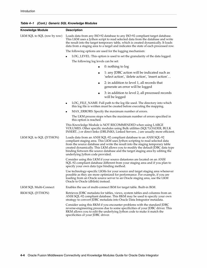
Introduction
4-4 Oracle Fusion Middleware Connectivity and Knowledge Modules Guide for Oracle Data Integrator
LKM SQL to SQL (row by row) Loads data from any ISO-92 database to any ISO-92 compliant target database. This LKM uses a Jython script to read selected data from the database and write the result into the target temporary table, which is created dynamically. It loads data from a staging area to a target and indicates the state of each processed row.
The following options are used for the logging mechanism:
■ LOG_LEVEL: This option is used to set the granularity of the data logged.
The following log levels can be set:
■ 0: nothing to log
■ 1: any JDBC action will be indicated such as 'select action', 'delete action', 'insert action'…
■ 2: in addition to level 1, all records that generate an error will be logged
■ 3: in addition to level 2, all processed records will be logged
■ LOG_FILE_NAME: Full path to the log file used. The directory into which this log file is written must be created before executing the mapping.
■ MAX_ERRORS: Specify the maximum number of errors.
The LKM process stops when the maximum number of errors specified in this option is reached.
This Knowledge Module is NOT RECOMMENDED when using LARGE VOLUMES. Other specific modules using Bulk utilities (SQL*LOADER, BULK INSERT...) or direct links (DBLINKS, Linked Servers...) are usually more efficient.
LKM SQL to SQL (JYTHON) Loads data from an ANSI SQL-92 compliant database to an ANSI SQL-92 compliant staging area. This LKM uses Jython scripting to read selected data from the source database and write the result into the staging temporary table created dynamically. This LKM allows you to modify the default JDBC data type binding between the source database and the target staging area by editing the underlying Jython code provided.
Consider using this LKM if your source datastores are located on an ANSI SQL-92 compliant database different from your staging area and if you plan to specify your own data type binding method.
Use technology-specific LKMs for your source and target staging area whenever possible as they are more optimized for performance. For example, if you are loading from an Oracle source server to an Oracle staging area, use the LKM Oracle to Oracle (dblink) instead.
LKM SQL Multi-Connect Enables the use of multi-connect IKM for target table. Built-in IKM.
RKM SQL (JYTHON) Retrieves JDBC metadata for tables, views, system tables and columns from an ANSI SQL-92 compliant database. This RKM may be used to specify your own strategy to convert JDBC metadata into Oracle Data Integrator metadata.
Consider using this RKM if you encounter problems with the standard JDBC reverse-engineering process due to some specificities of your JDBC driver. This RKM allows you to edit the underlying Jython code to make it match the specificities of your JDBC driver.
Table 4–1 (Cont.) Generic SQL Knowledge Modules
Knowledge Module Description

Setting up the Topology
Generic SQL 4-5
4.2 Installation and ConfigurationMake sure you have read the information in this section before you start using the generic SQL Knowledge Modules:
■ System Requirements and Certifications
■ Technology-Specific Requirements
■ Connectivity Requirements
4.2.1 System Requirements and CertificationsBefore performing any installation you should read the system requirements and certification documentation to ensure that your environment meets the minimum installation requirements for the products you are installing.
The list of supported platforms and versions is available on Oracle Technical Network (OTN):
http://www.oracle.com/technology/products/oracle-data-integrator/index.html.
4.2.2 Technology-Specific RequirementsSee the Technology Specific Requirements section of the specific technology chapter for more information.
If your technology does not have a dedicated chapter in this guide, see the documentation of your technology for any technology-specific requirements.
4.2.3 Connectivity RequirementsSee the Connectivity Requirements section of the specific technology chapter for more information.
The Java Database Connectivity (JDBC) is the standard for connecting to a database and other data sources. If your technology does not have a dedicated chapter in this guide, see the documentation of your technology for the JDBC configuration information, including the required driver files, the driver name, and the JDBC URL format.
4.3 Setting up the TopologySetting up the Topology consists in:
1. Creating a Data Server
SKM SQL Generates data access Web services for ANSI SQL-92 compliant databases. Data access services include data manipulation operations such as adding, removing, updating or filtering records as well as changed data capture operations such as retrieving changed data. Data manipulation operations are subject to integrity check as defined by the constraints of your datastores.
Consider using this SKM if you plan to generate and deploy data manipulation or changed data capture web services to your Service Oriented Architecture infrastructure. Use specific SKMs instead if available for your database
Table 4–1 (Cont.) Generic SQL Knowledge Modules
Knowledge Module Description

Setting up an Integration Project
4-6 Oracle Fusion Middleware Connectivity and Knowledge Modules Guide for Oracle Data Integrator
2. Creating a Physical Schema
4.3.1 Creating a Data ServerCreate a data server under the ANSI SQL-92 compliant technology listed in the Physical Architecture accordion using the standard procedure, as described in "Creating a Data Server" of the Developer's Guide for Oracle Data Integrator.
If your technology has a dedicated chapter in this guide, see this chapter for more information. For other technologies, see the documentation of your technology for the JDBC driver name and JDBC URL format.
4.3.2 Creating a Physical SchemaCreate a Physical Schema using the standard procedure, as described in "Creating a Physical Schema" of the Developer's Guide for Oracle Data Integrator.
If your technology has a dedicated chapter in this guide, see this chapter for more information.
4.4 Setting up an Integration ProjectSetting up a Project using an ANSI SQL-92 compliant database follows the standard procedure. See "Creating an Integration Project" of the Developer's Guide for Oracle Data Integrator.
The recommended knowledge modules to import into your project for getting started depend on the corresponding technology. If your technology has a dedicated chapter in this guide, see this chapter for more information.
4.5 Creating and Reverse-Engineering a ModelThis section contains the following topics:
■ Create a Data Model
■ Reverse-engineer a Data Model
4.5.1 Create a Data ModelCreate a data model based on the ANSI SQL-92 compliant technology using the standard procedure, as described in "Creating a Model" of the Developer's Guide for Oracle Data Integrator.
If your technology has a dedicated chapter in this guide, see this chapter for more information.
4.5.2 Reverse-engineer a Data ModelANSI SQL-92 standard compliant technologies support both types of reverse-engineering, the Standard reverse-engineering, which uses only the abilities of the JDBC driver, and the Customized reverse-engineering, which uses a RKM which provides logging features.
In most of the cases, consider using the standard JDBC reverse engineering instead of the RKM SQL (Jython). However, you can use this RKM as a starter if you plan to enhance it by adding your own metadata reverse-engineering behavior.

Designing a Mapping
Generic SQL 4-7
Standard Reverse-EngineeringTo perform a Standard Reverse- Engineering on ANSI SQL-92 technologies use the usual procedure, as described in "Reverse-engineering a Model" of the Developer's Guide for Oracle Data Integrator.
If your technology has a dedicated chapter in this guide, see this chapter for more information.
Customized Reverse-EngineeringTo perform a Customized Reverse-Engineering on ANSI SQL-92 technologies with a RKM, use the usual procedure, as described in "Reverse-engineering a Model" of the Developer's Guide for Oracle Data Integrator. This section details only the fields specific to the usage of the RKM SQL (Jython):
This RKM provides two logging options:
■ USE_LOG: Set to Yes if you want the reverse-engineering to process log details in a log file.
■ LOG_FILE_NAME: Enter the name for the log file. Note that the directory into which this log file is written must be created before executing the mapping.
4.6 Setting up Changed Data CaptureOracle Data Integrator does not provide journalizing Knowledge Modules for ANSI SQL-92 compliant technologies.
4.7 Setting up Data QualityOracle Data Integrator provides the CKM SQL for checking data integrity against constraints defined on an ANSI SQL-92 compliant table. See "Flow Control and Static Control" in the Developer's Guide for Oracle Data Integrator for details.
4.8 Designing a Mapping You can use ANSI SQL-92 compliant technologies as a source, staging area or a target of a mapping. It is also possible to create ETL-style mappings based on an ANSI SQL-92 compliant technology.
The KM choice for a mapping or a check determines the abilities and performances of this mapping or check. The recommendations below help in the selection of the KM for different situations concerning a data server based on an ANSI SQL-92 compliant technology.
4.8.1 Loading Data From and to an ANSI SQL-92 Compliant TechnologyANSI SQL-92 compliant technologies can be used as a source, target or staging area of a mapping. The LKM choice in the Loading Knowledge Module tab to load data between an ANSI SQL-92 compliant technology and another type of data server is essential for the performance of a mapping.
4.8.1.1 Loading Data from an ANSI SQL-92 Compliant TechnologyThe generic KMs that are listed in Table 4–2 implement methods for loading data from an ANSI SQL-92 compliant database to a target or staging area database. In addition to these KMS, Oracle Data Integrator provides KMs specific to the target or staging area

Designing a Mapping
4-8 Oracle Fusion Middleware Connectivity and Knowledge Modules Guide for Oracle Data Integrator
database. If your technology has a dedicated chapter in this guide, see this chapter for more information.
4.8.1.2 Loading Data to an ANSI SQL-92 Compliant TechnologyThe generic KMs that are listed in Table 4–3 implement methods for loading data from a source or staging area into an ANSI SQL-92 compliant database. In addition to these KMs, Oracle Data Integrator provides KMs specific to the source or staging area database. If your technology has a dedicated chapter in this guide, see this chapter for more information.
Table 4–2 KMs to Load from an ANSI SQL-92 Compliant Technology
Source or Staging Area KM Notes
ANSI SQL-92 compliant technology
LKM SQL to SQL Standard KM for SQL-92 to SQL-92 transfers.
ANSI SQL-92 compliant technology
LKM SQL to SQL (Built-in)
Built-in KM for SQL-92 to SQL-92 transfers through the agent using JDBC.
ANSI SQL-92 compliant technology
LKM SQL to SQL (Jython) This LKM uses Jython scripting to read selected data from the source database and write the result into the staging temporary table created dynamically. This LKM allows you to modify the default JDBC data types binding between the source database and the target staging area by editing the underlying Jython code provided.
ANSI SQL-92 compliant technology
LKM SQL to SQL (row by row)
This LKM uses row by row logging.
ANSI SQL-92 compliant technology
LKM SQL to File Built-in KM for SQL-92 to flat file transfers.
Table 4–3 KMs to Load to an ANSI SQL-92 Compliant Technology
Source or Staging Area KM Notes
File LKM File to SQL Standard KM
ANSI SQL-92 compliant technology
LKM SQL to SQL Standard KM
ANSI SQL-92 compliant technology
LKM SQL to SQL (Built-in)
Built-in KM for SQL-92 to SQL-92 transfers through the agent using JDBC.
ANSI SQL-92 compliant technology
LKM SQL to SQL (Jython) This LKM uses Jython scripting to read selected data from the source database and write the result into the staging temporary table created dynamically. This LKM allows you to modify the default JDBC data types binding between the source database and the target staging area by editing the underlying Jython code provided.
ANSI SQL-92 compliant technology
LKM SQL to SQL (row by row)
This LKM uses row by row logging.

Designing a Mapping
Generic SQL 4-9
4.8.2 Integrating Data in an ANSI SQL-92 Compliant TechnologyAn ANSI SQL-92 compliant technology can be used as a target of a mapping. The IKM choice in the Integration Knowledge Module tab determines the performance and possibilities for integrating.
The KMs listed in Table 4–4 implement methods for integrating data into an ANSI SQL-92 compliant target. In addition to these KMs, Oracle Data Integrator provides KMs specific to the source or staging area database. See the corresponding technology chapter for more information.
4.8.3 Designing an ETL-Style MappingSee "Creating a Mapping" in the Developer's Guide for Oracle Data Integrator for generic information on how to design mappings. This section describes how to design an ETL-style mapping where the staging area and target are ANSI SQL-92 compliant.
In an ETL-style mapping, ODI processes the data in a staging area, which is different from the target. Oracle Data Integrator provides two ways for loading the data from an ANSI SQL-92 compliant staging area to an ANSI SQL-92 compliant target:
■ Using a Multi-connection IKM
■ Using a LKM and a mono-connection IKM
Depending on the KM strategy that is used, flow and static control are supported.
Using a Multi-connection IKMA multi-connection IKM allows updating a target where the staging area and sources are on different data servers.
Table 4–4 KMs to Integrate Data in an ANSI SQL-92 Compliant Technology
Source or Staging Area KM Notes
ANSI SQL-92 compliant technology
IKM SQL Control Append Uses Bulk data movement inside data server. Supports Flow Control.
ANSI SQL-92 compliant technology
IKM SQL Incremental Update Uses Bulk data movement inside data server. Supports Flow Control.
ANSI SQL-92 compliant technology
IKM SQL Incremental Update (row by row)
Uses Bulk data movement inside data server, processes data row by row. Supports Flow Control.
ANSI SQL-92 compliant technology
IKM SQL Insert Uses SQL INSERT statement for data movement. Built-in KM.
ANSI SQL-92 compliant technology
IKM SQL Update Uses SQL UPDATE statement for data movement. Built-in KM.
ANSI SQL-92 compliant technology
IKM SQL Merge Uses SQL MERGE statement for data movement. Built-in KM.
ANSI SQL-92 compliant technology
IKM SQL to File Append Uses agent for data movement. Supports Flow Control.
ANSI SQL-92 compliant technology
IKM SQL to SQL Incremental Update
Uses agent or JYTHON for data movement. Supports Flow Control.
ANSI SQL-92 compliant technology
IKM SQL to SQL Control Append
Uses agent for control append strategies. Supports Flow Control.

Designing a Mapping
4-10 Oracle Fusion Middleware Connectivity and Knowledge Modules Guide for Oracle Data Integrator
Oracle Data Integrator provides the following multi-connection IKMs for ANSI SQL-92 compliant technologies: IKM SQL to SQL Incremental Update and IKM SQL to SQL Control Append.
See Table 4–5 for more information on when to use a multi-connection IKM.
To use a multi-connection IKM in an ETL-style mapping:
1. Create a mapping with an ANSI SQL-92 compliant staging area and target using the standard procedure as described in "Creating a Mapping" in the Developer's Guide for Oracle Data Integrator. This section describes only the ETL-style specific steps.
2. Change the staging area for the mapping to the logical schema of the source tables or a third schema. See "Configuring Execution Locations" in the Developer's Guide for Oracle Data Integrator for information about how to change the staging area.
3. In the Physical diagram, select an access point. The Property Inspector opens for this object.
4. In the Loading Knowledge Module tab, select an LKM to load from the source(s) to the staging area. See Table 4–5 to determine the LKM you can use.
5. Optionally, modify the KM options.
6. In the Physical diagram, select the Target by clicking its title. The Property Inspector opens for this object.
In the Integration Knowledge Module, select an ETL multi-connection IKM to load the data from the staging area to the target. See Table 4–5 to determine the IKM you can use.
Note the following when setting the KM options:
■ For IKM SQL to SQL Incremental Update
■ If you do not want to create any tables on the target system, set FLOW_CONTROL=false and FLOW_TABLE_LOCATION=STAGING.
Please note that this will lead to row-by-row processing and therefore significantly lower performance.
■ If you set the options FLOW_CONTROL or STATIC_CONTROL to true, select a CKM in the Check Knowledge Module tab. Note that if FLOW_CONTROL is set to true, the flow table is created on the target, regardless of the value of FLOW_TABLE_LOCATION.
■ The FLOW_TABLE_LOCATION option can take the following values:
Value Description Comment
TARGET Objects are created on the target.
Default value.
STAGING Objects are created only on the staging area, not on the target.
Cannot be used with flow control. Leads to row-by-row processing and therefore loss of performance.
NONE No objects are created on staging area nor target.
Cannot be used with flow control. Leads to row-by-row processing and therefore loss of performance. Requires to read source data twice in case of journalized data sources

Designing a Mapping
Generic SQL 4-11
Using a LKM and a mono-connection IKMIf there is no dedicated multi-connection IKM, use a standard exporting LKM in combination with a standard mono-connection IKM. The exporting LKM is used to load the flow table from the staging area to the target. The mono-connection IKM is used to integrate the data flow into the target table.
Oracle Data Integrator supports any ANSI SQL-92 standard compliant technology as a source, staging area, and target of an ETL-style mapping.
See Table 4–5 for more information on when to use the combination of a standard LKM and a mono-connection IKM.
To use an LKM and a mono-connection IKM in an ETL-style mapping:
1. Create a mapping with an ANSI SQL-92 compliant staging area and target using the standard procedure as described in "Creating a Mapping" in the Developer's Guide for Oracle Data Integrator. This section describes only the ETL-style specific steps.
2. Change the staging area for the mapping to the logical schema of the source tables or a third schema. See "Configuring Execution Locations" in the Developer's Guide for Oracle Data Integrator for information about how to change the staging area.
3. In the Physical diagram, select an access point. The Property Inspector opens for this object.
4. In the Loading Knowledge Module tab, select an LKM to load from the source(s) to the staging area. See Table 4–5 to determine the LKM you can use.
5. Optionally, modify the KM options.
6. Select the access point for the Staging Area. The Property Inspector opens for this object.
7. In the Loading Knowledge Module tab, select an LKM to load from the staging area to the target. See Table 4–5 to determine the LKM you can use.
8. Optionally, modify the options.
9. Select the Target by clicking its title. The Property Inspector opens for this object.
10. In the Integration Knowledge Module tab, select a standard mono-connection IKM to update the target. SeeTable 4–5 to determine the IKM you can use.

Designing a Mapping
4-12 Oracle Fusion Middleware Connectivity and Knowledge Modules Guide for Oracle Data Integrator
Table 4–5 KM Guidelines for ETL-Style Mappings based on an ANSI SQL-92 standard compliant technology
Source Staging Area TargetExporting LKM IKM KM Strategy Comment
ANSI SQL-92 standard compliant
ANSI SQL-92 standard compliant database
ANSI SQL-92 standard compliant database
NA IKM SQL to SQL Incremental Update
Multi-connection IKM
Allows an incremental update strategy with no temporary target-side objects. Use this KM if it is not possible to create temporary objects in the target server.
The application updates are made without temporary objects on the target, the updates are made directly from source to target. The configuration where the flow table is created on the staging area and not in the target should be used only for small volumes of data.
Supports flow and static control
ANSI SQL-92 standard compliant
ANSI SQL-92 standard compliant database
ANSI SQL-92 standard compliant database
NA IKM SQL to SQL Control Append
Multi-connection IKM
Use this KM strategy to perform control append.
Supports flow and static control.
ANSI SQL-92 standard compliant
ANSI SQL-92 standard compliant database
ANSI SQL-92 standard compliant database
any standard KM loading from an ANSI SQL-92 standard compliant technology to an ANSI SQL-92 standard compliant technology
IKM SQL Incremental Update
Mono-connection IKM
Allows an incremental update strategy

5
XML Files 5-1
5XML Files
This chapter describes how to work with XML files in Oracle Data Integrator.
This chapter includes the following sections:
■ Section 5.1, "Introduction"
■ Section 5.2, "Installation and Configuration"
■ Section 5.3, "Setting up the Topology"
■ Section 5.4, "Setting Up an Integration Project"
■ Section 5.5, "Creating and Reverse-Engineering a XML File"
■ Section 5.6, "Designing a Mapping"
■ Section 5.7, "Troubleshooting"
5.1 IntroductionOracle Data Integrator supports XML files integration through the Oracle Data Integrator Driver for XML.
5.1.1 ConceptsThe XML concepts map the Oracle Data Integrator concepts as follows: An XML file corresponds to a data server in Oracle Data Integrator. Within this data server, a single schema maps the content of the XML file.
The Oracle Data Integrator Driver for XML (XML driver) loads the hierarchical structure of the XML file into a relational schema. This relational schema is a set of tables located in the schema that can be queried or modified using SQL. The XML driver is also able to unload the relational schema back in the XML file.
The relational schema is reverse-engineered as a data model in ODI, with tables, columns, and constraints. This model is used like a normal relational data model in ODI. If the modified data within the relational schema needs to be written back to the XML file, the XML driver provides the capability to synchronize the relational schema into the file.
See Appendix B, "Oracle Data Integrator Driver for XML Reference" for more information on this driver.

Installation and Configuration
5-2 Oracle Fusion Middleware Connectivity and Knowledge Modules Guide for Oracle Data Integrator
5.1.2 Knowledge ModulesOracle Data Integrator provides the IKM XML Control Append for handling XML data. This Knowledge Module is a specific XML Knowledge Module. It has a specific option to synchronize the data from the relational schema to the file.
In addition to this KM, you can also use an XML data server as any SQL data server. XML data servers support both the technology-specific KMs sourcing or targeting SQL data servers, as well as the generic KMs. See Chapter 4, "Generic SQL" or the technology chapters for more information on these KMs.
5.2 Installation and ConfigurationMake sure you have read the information in this section before you start using the XML Knowledge Module:
■ System Requirements
■ Technologic Specific Requirements
■ Connectivity Requirements
5.2.1 System RequirementsBefore performing any installation you should read the system requirements and certification documentation to ensure that your environment meets the minimum installation requirements for the products you are installing.
The list of supported platforms and versions is available on Oracle Technical Network (OTN):
http://www.oracle.com/technology/products/oracle-data-integrator/index.html.
5.2.2 Technologic Specific RequirementsThere are no technology-specific requirements for using XML Files in Oracle Data Integrator.
5.2.3 Connectivity RequirementsThis section lists the requirements for connecting to XML database.
Oracle Data Integrator Driver for XMLXML files are accessed through the Oracle Data Integrator Driver for XML. This JDBC driver is installed with Oracle Data Integrator and requires no other installed component or configuration.
You must ask the system administrator for the following connection information:
■ The location of the DTD or XSD file associated with your XML file
■ The location of the XML file
5.3 Setting up the TopologySetting up the topology consists in:
1. Creating an XML Data Server

Setting up the Topology
XML Files 5-3
2. Creating a Physical Schema for XML
5.3.1 Creating an XML Data ServerAn XML data server corresponds to one XML file that is accessible to Oracle Data Integrator.
5.3.1.1 Creation of the Data ServerCreate a data server for the XML technology using the standard procedure, as described in "Creating a Data Server" of the Developer's Guide for Oracle Data Integrator. This section details only the fields required or specific for defining a File data server:
1. In the Definition tab:
■ Name: Name of the data server that will appear in Oracle Data Integrator.
■ User/Password: These fields are not used for XML data servers.
2. In the JDBC tab, enter the values according to the driver used:
■ JDBC Driver: com.sunopsis.jdbc.driver.xml.SnpsXmlDriver
■ JDBC URL: jdbc:snps:xml?[property=value&property=value...]
Table 5–1 lists the key properties of the Oracle Data Integrator Driver for XML. These properties can be specified in the JDBC URL.
See Appendix B, "Oracle Data Integrator Driver for XML Reference" for a detailed description of these properties and for a comprehensive list of all properties.
Table 5–1 JDBC Driver Properties
Property Value Notes
f <XML File location> XML file name. Use slash "/" in the path name instead of back slash "\". It is possible to use an HTTP, FTP or File URL to locate the file. Files located by URL are read-only.
d <DTD/XSD File location>
Description file: This file may be a DTD or XSD file. It is possible to use an HTTP, FTP or File URL to locate the file. Files located by URL are read-only.
Note that when no DTD or XSD file is present, the relational schema is built using only the XML file content. It is not recommended to reverse-engineer the data model from such a structure as one XML file instance may not contain all the possible elements described in the DTD or XSD, and data model may be incomplete.
re <Root element> Name of the element to take as the root table of the schema. This value is case sensitive. This property can be used for reverse-engineering for example a specific message definition from a WSDL file, or when several possible root elements exist in a XSD file.
ro true | false If true, the XML file is opened in read only mode.
s <schema name> Name of the relational schema where the XML file will be loaded. If this property is missing, a schema named after the five first letters of the XML file name will automatically be created.
This schema will be selected when creating the physical schema under the XML data server.
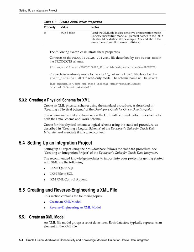
Setting Up an Integration Project
5-4 Oracle Fusion Middleware Connectivity and Knowledge Modules Guide for Oracle Data Integrator
The following examples illustrate these properties:
Connects to the PROD20100125_001.xml file described by products.xsd in the PRODUCTS schema.
jdbc:snps:xml?f=/xml/PROD20100125_001.xml&d=/xml/products.xsd&s=PRODUCTS
Connects in read-only mode to the staff_internal.xml file described by staff_internal.dtd in read-only mode. The schema name will be staff.
jdbc:snps:xml?f=/demo/xml/staff_internal.xml&d=/demo/xml/staff_internal.dtd&ro=true&s=staff
5.3.2 Creating a Physical Schema for XMLCreate an XML physical schema using the standard procedure, as described in "Creating a Physical Schema" of the Developer's Guide for Oracle Data Integrator.
The schema name that you have set on the URL will be preset. Select this schema for both the Data Schema and Work Schema.
Create for this physical schema a logical schema using the standard procedure, as described in "Creating a Logical Schema" of the Developer's Guide for Oracle Data Integrator and associate it in a given context.
5.4 Setting Up an Integration ProjectSetting up a Project using the XML database follows the standard procedure. See "Creating an Integration Project" of the Developer's Guide for Oracle Data Integrator.
The recommended knowledge modules to import into your project for getting started with XML are the following:
■ LKM SQL to SQL
■ LKM File to SQL
■ IKM XML Control Append
5.5 Creating and Reverse-Engineering a XML FileThis section contains the following topics:
■ Create an XML Model
■ Reverse-Engineering an XML Model
5.5.1 Create an XML ModelAn XML file model groups a set of datastores. Each datastore typically represents an element in the XML file.
cs true | false Load the XML file in case sensitive or insensitive mode. For case insensitive mode, all element names in the DTD file should be distinct (For example: Abc and abc in the same file will result in name collisions).
Table 5–1 (Cont.) JDBC Driver Properties
Property Value Notes

Designing a Mapping
XML Files 5-5
Create an XML Model using the standard procedure, as described in "Creating a Model" of the Developer's Guide for Oracle Data Integrator. Select the XML technology and the XML logical schema created when configuring the topology.
5.5.2 Reverse-Engineering an XML ModelXML supports standard reverse-engineering, which uses only the abilities of the XML driver.
It is recommended to reference a DTD or XSD file in the dtd or d parameters of the URL to reverse-engineer the structure from a generic description of the XML file structure. Reverse-engineering can use an XML instance file if no XSD or DTD is available. In this case, the relational schema structure will be inferred from the data contained in the XML file.
Standard Reverse-EngineeringTo perform a Standard Reverse- Engineering on XML use the usual procedure, as described in "Reverse-engineering a Model" of the Developer's Guide for Oracle Data Integrator.
The standard reverse-engineering process will automatically reverse-engineer the table from the relational schema generated by the XML driver. Note that these tables automatically include:
■ Primary keys (PK columns) to preserve parent-child elements relationships
■ Foreign keys (FK columns) to preserve parent-child elements relationships
■ Order identifier (ORDER columns) to preserve the order of elements in the XML file
These extra columns enable the mapping of the hierarchical XML structure into the relational schema. See XML to SQL Mapping in the Appendix B, "Oracle Data Integrator Driver for XML Reference" for more information.
5.6 Designing a MappingYou can use XML as a source or a target of a mapping.
The KM choice for a mapping or a check determines the abilities and performances of this mapping or check. The recommendations in this section help in the selection of the KM for different situations concerning an XML data server.
5.6.1 Notes about XML MappingsRead carefully these notes before working with XML in mappings.
5.6.1.1 Targeting an XML StructureWhen using a datastore of an XML model as a target of a mapping, you must make sure to load the driver-generated columns that are used for preserving the parent-child relationships and the order in the XML hierarchy. For example, if filling records for the region element into an XML structure as shown in Example 5–1, that correspond to a REGION table in the relational schema, you should load the columns REGION_ID and REGION_NAME of the REGION table. These two columns correspond to XML attributes.

Designing a Mapping
5-6 Oracle Fusion Middleware Connectivity and Knowledge Modules Guide for Oracle Data Integrator
Example 5–1 XML Structure
<country COUNTRY_ID="6" COUNTRY_NAME="Australia"> <region REGION_ID="72" REGION_NAME="Queensland"></country>
In Example 5–1 you must also load the following additional columns that are automatically created by the XML Driver in the REGION table:
■ REGIONPK: This column enables you to identify each <region> element.
■ REGIONORDER: This column enables you to order the <region> elements in the XML file (records are not ordered in a relational schema, whereas XML elements are ordered).
■ COUNTRYFK: This columns enables you to put the <region> element in relation with the <country> parent element. This value is equal to the COUNTRY.COUNTRYPK value for the Australia record in the COUNTRY table.
5.6.1.2 Synchronizing XML File and SchemaTo ensure a perfect synchronization of the data in an XML file and the data in the XML schema, the following commands have to be called:
■ Before using the tables of an XML model, either to read or update data, it is recommended that you use the SYNCHRONIZE FROM FILE command on the XML logical schema. This operation reloads the XML hierarchical data in the relational XML schema. The schema is loaded in the built-in or external database storage when first accessed. Subsequent changes made to the file are not automatically synchronized into the schema unless you issue this command.
■ After performing changes in the relational schema, you must unload this schema into the XML hierarchical data by calling the SYNCHRONIZE ALL or SYNCHRONIZE FROM DATABASE commands on the XML Logical Schema. The IKM XML Control Append implements this synchronize command.
These commands must be executed in procedures in the packages before (and after) the mappings and procedures manipulating the XML schema.
See Appendix B, "Oracle Data Integrator Driver for XML Reference" for more information on these commands.
5.6.1.3 Handling Large XML FilesLarge XML files can be handled with high performance with Oracle Data Integrator.
The default driver configuration stores the relational schema in a built-in engine in memory. It is recommended to consider the use of external database storage for handling large XML files.
See Section B.2.3.1, "Schema Storage" for more information on these commands.
5.6.2 Loading Data from and to XMLAn XML file can be used as a mapping's source or target. The LKM choice in the Loading Knowledge Module tab that is used to load data between XML files and other types of data servers is essential for the performance of the mapping.

Designing a Mapping
XML Files 5-7
5.6.2.1 Loading Data from an XML SchemaUse the Generic SQL KMs or the KMs specific to the other technology involved to load data from an XML database to a target or staging area database.
Table 5–2 lists some examples of KMs that you can use to load from an XML source to a staging area:
5.6.2.2 Loading Data to an XML SchemaIt is not advised to use an XML schema as a staging area, except if XML is the target of the mapping and you wish to use the target as a staging area. In this case, it might be required to load data to an XML schema.
Use the Generic SQL KMs or the KMs specific to the other technology involved to load data from a source or staging area into an XML schema.
Table 5–3 lists some examples of KMs that you can use to load from a source to an XML staging area.
5.6.3 Integrating Data in XMLXML can be used as a target of a mapping. The data integration strategies in XML concern loading from the staging area to XML. The IKM choice in the Integration Knowledge Module tab determines the performances and possibilities for integrating.
The IKM XML Control Append integrates data into the XML schema and has an option to synchronize the data to the file. In addition to this KM, you can also use the Generic SQL KMs or the KMs specific to the other technology involved. Note that if using generic or technology-specific KMs, you must manually perform the synchronize operation to write the changes made in the schema to the XML file.
Table 5–4 lists some examples of KMs that you can use to integrate data:
■ From a staging area to an XML target
■ From an XML staging area to an XML target. Note that in this case the staging area is on the XML target.
Table 5–2 KMs to Load from XML to a Staging Area
Staging Area KM Notes
Microsoft SQL Server
LKM SQL to MSSQL (BULK) Uses SQL Server's bulk loader.
Oracle LKM SQL to Oracle Faster than the Generic LKM (Uses Statistics)
All LKM SQL to SQL Generic KM to load data between an ANSI SQL-92 source and an ANSI SQL-92 staging area.
Table 5–3 KMs to Load to an XML Schema
Source KM Notes
File LKM File to SQL Generic KM to load a file in a ANSI SQL-92 staging area.
All LKM SQL to SQL Generic KM to load data between an ANSI SQL-92 source and an ANSI SQL-92 staging area.

Troubleshooting
5-8 Oracle Fusion Middleware Connectivity and Knowledge Modules Guide for Oracle Data Integrator
5.7 TroubleshootingThis section provides information on how to troubleshoot problems that you might encounter when using XML in Oracle Data Integrator. It contains the following topics:
■ Detect the Errors Coming from XML
■ Common Errors
5.7.1 Detect the Errors Coming from XMLErrors appear often in Oracle Data Integrator in the following way:
java.sql.SQLException: No suitable driverat ... at ... ...
the java.sql.SQLExceptioncode simply indicates that a query was made through the JDBC driver, which has returned an error. This error is frequently a database or driver error, and must be interpreted in this direction.
Only the part of text in bold must first be taken in account. It must be searched in the XML driver documentation. If it contains a specific error code, like here, the error can be immediately identified.
If such an error is identified in the execution log, it is necessary to analyze the SQL code send to the database to find the source of the error. The code is displayed in the description tab of the task in error.
5.7.2 Common ErrorsThis section describes the most common errors with XML along with the principal causes. It contains the following topics:
■ No suitable driver
The JDBC URL is incorrect. Check that the URL syntax is valid.
■ File <XML file> is already locked by another instance of the XML driver.
The XML file is locked by another user/application. Close all application that might be using the XML file. If such an application has crashed, then remove the .lck file remaining in the XML file's directory.
■ The DTD file "xxxxxxx.dtd" doesn't exist
This exception may occur when trying to load an XML file by the command LOAD FILE. The error message can have two causes:
■ The path of the DTD file is incorrect.
Table 5–4 KMs to Integrate Data in an XML File
Mode Staging Area KM Notes
Update XML IKM SQL Incremental Update Generic KM
Append XML IKM SQL Control Append Generic KM
Append All RDBMS IKM SQL to SQL Append Generic KM

Troubleshooting
XML Files 5-9
■ The corresponding XML file was already opened by another schema (during connection for instance).
■ Table not found: S0002 Table not found: <table name> in statement [<SQL statement>]
The table you are trying to access does not exist in the schema.
■ Column not found: S0022 Column not found: <column name> in statement [<SQL statement>]
The column you are trying to access does not exist in the tables specified in the statement.

Troubleshooting
5-10 Oracle Fusion Middleware Connectivity and Knowledge Modules Guide for Oracle Data Integrator

6
Complex Files 6-1
6Complex Files
This chapter describes how to work with Complex Files in Oracle Data Integrator.
This chapter includes the following sections:
■ Section 6.1, "Introduction"
■ Section 6.2, "Installation and Configuration"
■ Section 6.3, "Setting up the Topology"
■ Section 6.4, "Setting Up an Integration Project"
■ Section 6.5, "Creating and Reverse-Engineering a Complex File Model"
■ Section 6.6, "Designing a Mapping"
6.1 IntroductionOracle Data Integrator supports several files types. This chapter describes how to work with the Complex (or native) File format. See Chapter 3, "Files" for information about simple fixed or delimited files containing ASCII or EBCDIC data.
For complex files it is possible to build a Native Schema description file that describes the file structure. Using this Native Schema (nXSD) description and the Oracle Data Integrator Driver for Complex Files, Oracle Data Integrator is able to reverse-engineer, read and write information from complex files.
See "Native Format Builder Wizard" in the User's Guide for Technology Adapters for more information on the Native Schema format, and Appendix C, "Oracle Data Integrator Driver for Complex Files Reference" for reference information on the Complex File driver.
6.1.1 ConceptsThe Oracle Data Integrator Driver for Complex Files (Complex File driver) converts native format to a relational structure and exposes this relational structure as a data model in Oracle Data Integrator.
The Complex File driver translates internally the native file into an XML structure, as defined in the Native Schema (nXSD) description and from this XML file it generates a relational schema that is consumed by Oracle Data Integrator. The overall mechanism is shown in Figure 6–1.
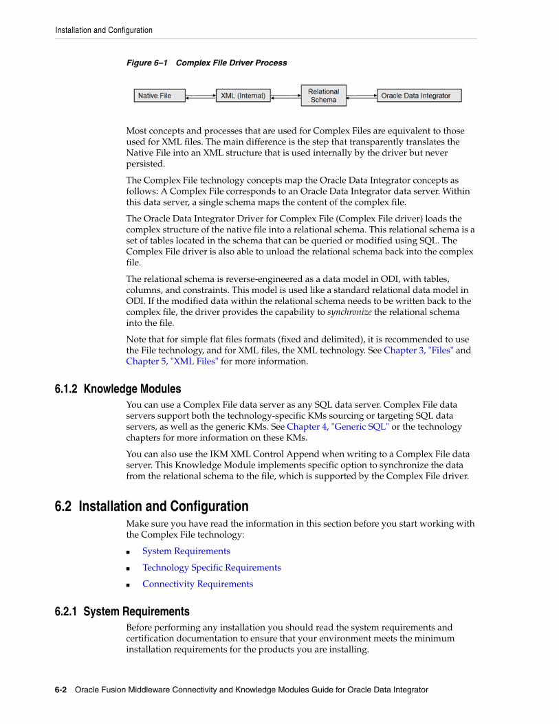
Installation and Configuration
6-2 Oracle Fusion Middleware Connectivity and Knowledge Modules Guide for Oracle Data Integrator
Figure 6–1 Complex File Driver Process
Most concepts and processes that are used for Complex Files are equivalent to those used for XML files. The main difference is the step that transparently translates the Native File into an XML structure that is used internally by the driver but never persisted.
The Complex File technology concepts map the Oracle Data Integrator concepts as follows: A Complex File corresponds to an Oracle Data Integrator data server. Within this data server, a single schema maps the content of the complex file.
The Oracle Data Integrator Driver for Complex File (Complex File driver) loads the complex structure of the native file into a relational schema. This relational schema is a set of tables located in the schema that can be queried or modified using SQL. The Complex File driver is also able to unload the relational schema back into the complex file.
The relational schema is reverse-engineered as a data model in ODI, with tables, columns, and constraints. This model is used like a standard relational data model in ODI. If the modified data within the relational schema needs to be written back to the complex file, the driver provides the capability to synchronize the relational schema into the file.
Note that for simple flat files formats (fixed and delimited), it is recommended to use the File technology, and for XML files, the XML technology. See Chapter 3, "Files" and Chapter 5, "XML Files" for more information.
6.1.2 Knowledge ModulesYou can use a Complex File data server as any SQL data server. Complex File data servers support both the technology-specific KMs sourcing or targeting SQL data servers, as well as the generic KMs. See Chapter 4, "Generic SQL" or the technology chapters for more information on these KMs.
You can also use the IKM XML Control Append when writing to a Complex File data server. This Knowledge Module implements specific option to synchronize the data from the relational schema to the file, which is supported by the Complex File driver.
6.2 Installation and ConfigurationMake sure you have read the information in this section before you start working with the Complex File technology:
■ System Requirements
■ Technology Specific Requirements
■ Connectivity Requirements
6.2.1 System RequirementsBefore performing any installation you should read the system requirements and certification documentation to ensure that your environment meets the minimum installation requirements for the products you are installing.

Setting up the Topology
Complex Files 6-3
The list of supported platforms and versions is available on Oracle Technical Network (OTN):
http://www.oracle.com/technology/products/oracle-data-integrator/index.html.
6.2.2 Technology Specific RequirementsThere are no technology-specific requirements for using Complex Files in Oracle Data Integrator.
6.2.3 Connectivity RequirementsThis section lists the requirements for connecting to complex files.
Oracle Data Integrator Driver for Complex FilesComplex files are accessed through the Oracle Data Integrator Driver for Complex File. This JDBC driver is installed with Oracle Data Integrator and requires no other installed component or configuration.
You must ask the system administrator for the following connection information:
■ The location of the Native Schema (nXSD) file associated with your native file
■ The location of the native complex file
6.3 Setting up the TopologySetting up the topology consists in:
1. Creating a Complex File Data Server
2. Creating a Complex File Physical Schema
6.3.1 Creating a Complex File Data ServerA Complex File data server corresponds to one native file that is accessible to Oracle Data Integrator.
6.3.1.1 Creation of the Data ServerCreate a data server for the Complex File technology using the standard procedure, as described in "Creating a Data Server" of the Developer's Guide for Oracle Data Integrator. This section details only the fields required or specific for defining a Complex File data server:
1. In the Definition tab:
■ Name: Name of the data server that will appear in Oracle Data Integrator.
■ User/Password: These fields are not used for Complex File data servers.
2. In the JDBC tab, enter the following values:
■ JDBC Driver: oracle.odi.jdbc.driver.file.complex.ComplexFileDriver
■ JDBC URL: jdbc:snps:complexfile?f=<native file location>&d=<native schema>&re=<root element name>&s=<schema name>[&<property>=<value>...]

Setting Up an Integration Project
6-4 Oracle Fusion Middleware Connectivity and Knowledge Modules Guide for Oracle Data Integrator
Table 6–1 lists the key properties of the Oracle Data Integrator Driver for Complex Files. These properties can be specified in the JDBC URL.
See Appendix C, "Oracle Data Integrator Driver for Complex Files Reference" for a detailed description of these properties and for a comprehensive list of all properties.
The following example illustrates these properties:
Connects to the PROD20100125_001.csv file described by products.nxsd and expose this file as a relational structure in the PRODUCT Schema.
jdbc:snps:complexfile?f=/infiles/PROD20100125_001.csv&d=/infiles/products.nxsd&re=root&s=PRODUCTS
6.3.2 Creating a Complex File Physical SchemaCreate a Complex File physical schema using the standard procedure, as described in "Creating a Physical Schema" of the Developer's Guide for Oracle Data Integrator.
The schema name that you have set on the URL will be preset. Select this schema for both the Data Schema and Work Schema.
Create for this physical schema a logical schema using the standard procedure, as described in "Creating a Logical Schema" of the Developer's Guide for Oracle Data Integrator and associate it in a given context.
6.4 Setting Up an Integration ProjectSetting up a project using the Complex File technology follows the standard procedure. See "Creating an Integration Project" of the Developer's Guide for Oracle Data Integrator.
Note: The s parameter is optional. If the s parameter is not specified, Oracle Data Integrator specifies a schema for you.
Table 6–1 Complex File Driver Properties
Property Value Notes
f <native file name> Native file location. Use slash "/" in the path name instead of back slash "\". It is possible to use an HTTP, FTP or File URL to locate the file. Files located by URL are read-only. This parameter is mandatory.
d <native schema> Native Schema (nXSD) file location. This parameter is mandatory.
re <root element> Name of the element to take as the root table of the schema. This value is case sensitive. This property can be used for reverse-engineering for example a specific section of the Native Schema. This parameter is mandatory.
s <schema name> Name of the relational schema where the complex file will be loaded. This parameter is optional.
This schema will be selected when creating the physical schema under the Complex File data server.

Designing a Mapping
Complex Files 6-5
It is recommended to import the following knowledge modules into your project for getting started:
■ LKM SQL to SQL
■ LKM File to SQL
■ IKM XML Control Append
In addition to these knowledge modules, you can also import file knowledge modules specific to the other technologies involved in your product.
6.5 Creating and Reverse-Engineering a Complex File ModelThis section contains the following topics:
■ Create a Complex File Model
■ Reverse-engineer a Complex File Model
6.5.1 Create a Complex File ModelA Complex File model groups a set of datastores. Each datastore typically represents an element in the intermediate XML file generated from the native file using the native schema.
Create a Complex File model using the standard procedure, as described in "Creating a Model" of the Developer's Guide for Oracle Data Integrator.
6.5.2 Reverse-engineer a Complex File ModelThe Complex File technology supports standard reverse-engineering, which uses only the abilities of the Complex File driver.
Standard Reverse-EngineeringTo perform a Standard Reverse- Engineering with a Complex File model use the usual procedure, as described in "Reverse-engineering a Model" of the Developer's Guide for Oracle Data Integrator.
This reverse-engineering uses the same process as the reverse-engineering of XML Files. The native schema (nXSD) provided in the data server URL is used as the XSD file to describe the XML structure. See Section 5.5.2, "Reverse-Engineering an XML Model" and XML to SQL Mapping for more information.
6.6 Designing a MappingYou can use a complex file as a source or a target of a mapping.
The KM choice for a mapping or a check determines the abilities and performances of this mapping or check. The recommendations below help in the selection of the KM for different situations concerning a Complex File data server.
Complex File data models are handled in mappings similarly to XML structures. For example, the Synchronization model is the same for complex files and XML files and the same knowledge modules can be used for both technologies.
See Section 5.6, "Designing a Mapping" in Chapter 5, "XML Files" for more information.

Designing a Mapping
6-6 Oracle Fusion Middleware Connectivity and Knowledge Modules Guide for Oracle Data Integrator

7
Microsoft SQL Server 7-1
7Microsoft SQL Server
This chapter describes how to work with Microsoft SQL Server in Oracle Data Integrator.
This chapter includes the following sections:
■ Section 7.1, "Introduction"
■ Section 7.2, "Installation and Configuration"
■ Section 7.3, "Setting up the Topology"
■ Section 7.4, "Setting Up an Integration Project"
■ Section 7.5, "Creating and Reverse-Engineering a Microsoft SQL Server Model"
■ Section 7.6, "Setting up Changed Data Capture"
■ Section 7.7, "Setting up Data Quality"
■ Section 7.8, "Designing a Mapping"
7.1 IntroductionOracle Data Integrator (ODI) seamlessly integrates data in Microsoft SQL Server. Oracle Data Integrator features are designed to work best with Microsoft SQL Server, including reverse-engineering, changed data capture, data integrity check, and mappings.
7.1.1 ConceptsThe Microsoft SQL Server concepts map the Oracle Data Integrator concepts as follows: A Microsoft SQL Server server corresponds to a data server in Oracle Data Integrator. Within this server, a database/owner pair maps to an Oracle Data Integrator physical schema. A set of related objects within one database corresponds to a data model, and each table, view or synonym will appear as an ODI datastore, with its attributes, columns and constraints.
Oracle Data Integrator uses Java Database Connectivity (JDBC) to connect to Microsoft SQL Server.
7.1.2 Knowledge ModulesOracle Data Integrator provides the Knowledge Modules (KM) listed in Table 7–1 for handling Microsoft SQL Server data. In addition to these specific Microsoft SQL Server Knowledge Modules, it is also possible to use the generic SQL KMs with Microsoft SQL Server. See Chapter 4, "Generic SQL" for more information.

Installation and Configuration
7-2 Oracle Fusion Middleware Connectivity and Knowledge Modules Guide for Oracle Data Integrator
7.2 Installation and ConfigurationMake sure you have read the information in this section before you start working with the Microsoft SQL Server technology:
■ System Requirements and Certifications
■ Technology Specific Requirements
■ Connectivity Requirements
7.2.1 System Requirements and CertificationsBefore performing any installation you should read the system requirements and certification documentation to ensure that your environment meets the minimum installation requirements for the products you are installing.
The list of supported platforms and versions is available on Oracle Technical Network (OTN):
http://www.oracle.com/technology/products/oracle-data-integrator/index.html.
Table 7–1 Microsoft SQL Server Knowledge Modules
Knowledge Module Description
IKM MSSQL Incremental Update Integrates data in a Microsoft SQL Server target table in incremental update mode.
IKM MSSQL Slowly Changing Dimension Integrates data in a Microsoft SQL Server target table used as a Type II Slowly Changing Dimension in your Data Warehouse.
JKM MSSQL Consistent Creates the journalizing infrastructure for consistent journalizing on Microsoft SQL Server tables using triggers.
JKM MSSQL Simple Creates the journalizing infrastructure for simple journalizing on Microsoft SQL Server tables using triggers.
LKM File to MSSQL (BULK) Loads data from a File to a Microsoft SQL Server staging area database using the BULK INSERT SQL command.
LKM MSSQL to MSSQL (BCP) Loads data from a Microsoft SQL Server source database to a Microsoft SQL Server staging area database using the native BCP out/BCP in commands.
LKM MSSQL to MSSQL (LINKED SERVERS)
Loads data from a Microsoft SQL Server source database to a Microsoft SQL Server staging area database using the native linked servers feature.
LKM MSSQL to ORACLE (BCP SQLLDR) Loads data from a Microsoft SQL Server to an Oracle database (staging area) using the BCP and SQLLDR utilities.
LKM SQL to MSSQL (BULK) Loads data from any ANSI SQL-92 source database to a Microsoft SQL Server staging area database using the native BULK INSERT SQL command.
LKM SQL to MSSQL Loads data from any ANSI SQL-92 source database to a Microsoft SQL Server staging area. This LKM is similar to the standard LKM SQL to SQL described in Chapter 4, "Generic SQL" except that you can specify some additional specific Microsoft SQL Server parameters.
RKM MSSQL Retrieves metadata for Microsoft SQL Server objects: tables, views and synonyms, as well as columns and constraints.

Installation and Configuration
Microsoft SQL Server 7-3
7.2.2 Technology Specific RequirementsSome of the Knowledge Modules for Microsoft SQL Server use specific features of this database. The following restrictions apply when using these Knowledge Modules. See the Microsoft SQL Server documentation for additional information on these topics.
7.2.2.1 Using the BULK INSERT CommandThis section describes the requirements that must be met before using the BULK INSERT command with Microsoft SQL Server:
■ The file to be loaded by the BULK INSERT command needs to be accessible from the Microsoft SQL Server instance machine. It could be located on the file system of the server or reachable from a UNC (Unique Naming Convention) path.
■ UNC file paths are supported but not recommended as they may decrease performance.
■ For performance reasons, it is often recommended to install Oracle Data Integrator Agent on the target server machine.
7.2.2.2 Using the BCP CommandThis section describes the requirements that must be met before using the BCP command with Microsoft SQL Server:
■ The BCP utility as well as the Microsoft SQL Server Client Network Utility must be installed on the machine running the Oracle Data Integrator Agent.
■ The server names defined in the Topology must match the Microsoft SQL Server Client connect strings used for these servers.
■ White spaces in server names defined in the Client Utility are not supported.
■ UNC file paths are supported but not recommended as they may decrease performance.
■ The target staging area database must have the option select into/bulk copy.
■ Execution can remain pending if the file generated by the BCP program is empty.
■ For performance reasons, it is often recommended to install Oracle Data Integrator Agent on the target server machine.
7.2.2.3 Using Linked ServersThis section describes the requirements that must be met before using linked servers with Microsoft SQL Server:
■ The user defined in the Topology to connect to the Microsoft SQL Server instances must have the following privileges:
■ The user must be the db_owner of the staging area databases
■ The user must have db_ddladmin role
■ For automatic link server creation, the user must have sysdamin privileges
■ The MSDTC Service must be started on both SQL Server instances (source and target). The following hints may help you configure this service:
■ The Log On As account for the MSDTC Service is a Network Service account (and not the 'LocalSystem' account).
■ MSDTC should be enabled for network transactions.

Setting up the Topology
7-4 Oracle Fusion Middleware Connectivity and Knowledge Modules Guide for Oracle Data Integrator
■ Windows Firewall should be configured to allow the MSDTC service on the network. By default, the Windows Firewall blocks the MSDTC program.
■ The Microsoft SQL Server must be started after MSDTC has completed its startup.
See the following links for more information about configuring the MSDTC Service:
■ http://support.microsoft.com/?kbid=816701
■ http://support.microsoft.com/?kbid=839279
7.2.3 Connectivity RequirementsThis section lists the requirements for connecting to a Microsoft SQL Server database.
JDBC DriverOracle Data Integrator is installed with a default Microsoft SQL Server Datadirect Driver. This drivers directly uses the TCP/IP network layer and requires no other installed component or configuration. You can alternatively use the drivers provided by Microsoft for SQL Server.
7.3 Setting up the TopologySetting up the Topology consists of:
1. Creating a Microsoft SQL Server Data Server
2. Creating a Microsoft SQL Server Physical Schema
7.3.1 Creating a Microsoft SQL Server Data ServerA Microsoft SQL Server data server corresponds to a Microsoft SQL Server server connected with a specific user account. This user will have access to several databases in this server, corresponding to the physical schemas in Oracle Data Integrator created under the data server.
7.3.1.1 Creation of the Data ServerCreate a data server for the Microsoft SQL Server technology using the standard procedure, as described in "Creating a Data Server" of the Developer's Guide for Oracle Data Integrator. This section details only the fields required or specific for defining a Microsoft SQL data server:
1. In the Definition tab:
■ Name: Name of the data server that will appear in Oracle Data Integrator
■ Server: Physical name of the data server
■ User/Password: Microsoft SQLServer user with its password
2. In the JDBC tab:
■ JDBC Driver: weblogic.jdbc.sqlserver.SQLServerDriver
■ JDBC URL: jdbc:weblogic:sqlserver://hostname:port[;property=value[;...]]

Creating and Reverse-Engineering a Microsoft SQL Server Model
Microsoft SQL Server 7-5
7.3.2 Creating a Microsoft SQL Server Physical SchemaCreate a Microsoft SQL Server physical schema using the standard procedure, as described in "Creating a Physical Schema" of the Developer's Guide for Oracle Data Integrator.
The work schema and data schema in this physical schema correspond each to a database/owner pair. The work schema should point to a temporary database and the data schema should point to the database hosting the data to integrate.
Create for this physical schema a logical schema using the standard procedure, as described in "Creating a Logical Schema" of the Developer's Guide for Oracle Data Integrator and associate it in a given context.
7.4 Setting Up an Integration ProjectSetting up a project using the Microsoft SQL Server database follows the standard procedure. See "Creating an Integration Project" of the Developer's Guide for Oracle Data Integrator.
It is recommended to import the following knowledge modules into your project for getting started with Microsoft SQL Server:
■ IKM MSSQL Incremental Update
■ IKM MSSQL Slowly Changing Dimension
■ JKM MSSQL Consistent
■ JKM MSSQL Simple
■ LKM File to MSSQL (BULK)
■ LKM MSSQL to MSSQL (BCP)
■ LKM MSSQL to MSSQL (LINKED SERVERS)
■ LKM MSSQL to ORACLE (BCP SQLLDR)
■ LKM SQL to MSSQL (BULK)
■ LKM SQL to MSSQL
■ CKM SQL. This generic KM is used for performing integrity check for SQL Server.
■ RKM MSSQL
7.5 Creating and Reverse-Engineering a Microsoft SQL Server ModelThis section contains the following topics:
■ Create a Microsoft SQL Server Model
■ Reverse-engineer a Microsoft SQL Server Model
7.5.1 Create a Microsoft SQL Server ModelCreate a Microsoft SQL Server Model using the standard procedure, as described in "Creating a Model" of the Developer's Guide for Oracle Data Integrator.

Setting up Changed Data Capture
7-6 Oracle Fusion Middleware Connectivity and Knowledge Modules Guide for Oracle Data Integrator
7.5.2 Reverse-engineer a Microsoft SQL Server ModelMicrosoft SQL Server supports both Standard reverse-engineering - which uses only the abilities of the JDBC driver - and Customized reverse-engineering, which uses a RKM to retrieve the metadata.
In most of the cases, consider using the standard JDBC reverse engineering for starting. Standard reverse-engineering with Microsoft SQL Server retrieves tables, views, and columns.
Consider switching to customized reverse-engineering for retrieving more metadata. Microsoft SQL Server customized reverse-engineering retrieves the tables, views, and synonyms. The RKM MSSQL also reverse-engineers columns that have a user defined data type and translates the user defined data type to the native data type.
Standard Reverse-EngineeringTo perform a Standard Reverse-Engineering on Microsoft SQL Server use the usual procedure, as described in "Reverse-engineering a Model" of the Developer's Guide for Oracle Data Integrator.
Customized Reverse-EngineeringTo perform a Customized Reverse-Engineering on Microsoft SQL Server with a RKM, use the usual procedure, as described in "Reverse-engineering a Model" of the Developer's Guide for Oracle Data Integrator. This section details only the fields specific to the Microsoft SQL Server technology:
1. In the Reverse Engineer tab of the Microsoft SQL Server Model, select the KM: RKM MSSQL.<project name>.
2. In the COMPATIBLE option, enter the Microsoft SQL Server version. This option decides whether to enable reverse synonyms. Note that only Microsoft SQLServer version 2005 and above support synonyms.
Note the following information when using this RKM:
■ The connection user must have SELECT privileges on any INFORMATION_SCHEMA views.
■ Only native data type will be saved for the attribute with user defined data type in the repository and model.
■ User defined data types implemented through a class of assembly in the Microsoft .NET Framework common language runtime (CLR) will not be reversed.
7.6 Setting up Changed Data CaptureThe ODI Microsoft SQL Server Knowledge Modules support the Changed Data Capture feature. See Chapter "Working with Changed Data Capture" of the Developer's Guide for Oracle Data Integrator for details on how to set up journalizing and how to use captured changes.
Microsoft SQL Server Journalizing Knowledge Modules support Simple Journalizing and Consistent Set Journalizing. The Microsoft SQL Server JKMs use triggers to capture data changes on the source tables.
Oracle Data Integrator provides the Knowledge Modules listed in Table 7–2 for journalizing Microsoft SQL Server tables.

Designing a Mapping
Microsoft SQL Server 7-7
Log-based changed data capture is possible with Microsoft SQL Server using the Oracle Changed Data Capture Adapters. See Chapter 19, "Oracle Changed Data Capture Adapters" for more information.
7.7 Setting up Data QualityOracle Data Integrator provides the generic CKM SQL for checking data integrity against constraints defined on a Microsoft SQL Server table. See "Flow Control and Static Control" in the Developer's Guide for Oracle Data Integrator for details.
See Chapter 4, "Generic SQL" for more information.
7.8 Designing a MappingYou can use Microsoft SQL Server as a source, staging area or a target of a mapping.
The KM choice for a mapping or a check determines the abilities and performance of this mapping or check. The recommendations in this section help in the selection of the KM for different situations concerning a Microsoft SQL Server data server.
7.8.1 Loading Data from and to Microsoft SQL ServerMicrosoft SQL Server can be used as a source, target or staging area of a mapping. The LKM choice in the Loading Knowledge Module tab to load data between Microsoft SQL Server and another type of data server is essential for the performance of a mapping.
7.8.1.1 Loading Data from Microsoft SQL ServerOracle Data Integrator provides Knowledge Modules that implement optimized methods for loading data from Microsoft SQL Server to a target or staging area database. These optimized Microsoft SQL Server KMs are listed in Table 7–3.
In addition to these KMs, you can also use the Generic SQL KMs or the KMs specific to the other technology involved to load data from Microsoft SQL Server to a target or staging area database.
Table 7–2 Microsoft SQL Server Journalizing Knowledge Modules
KM Notes
JKM MSSQL Consistent Creates the journalizing infrastructure for consistent journalizing on Microsoft SQL Server tables using triggers.
JKM MSSQL Simple Creates the journalizing infrastructure for simple journalizing on Microsoft SQL Server tables using triggers.
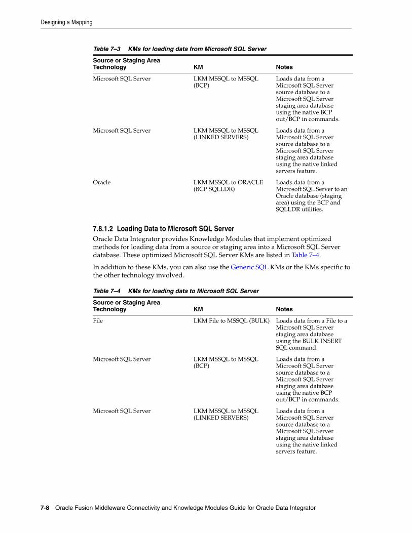
Designing a Mapping
7-8 Oracle Fusion Middleware Connectivity and Knowledge Modules Guide for Oracle Data Integrator
7.8.1.2 Loading Data to Microsoft SQL ServerOracle Data Integrator provides Knowledge Modules that implement optimized methods for loading data from a source or staging area into a Microsoft SQL Server database. These optimized Microsoft SQL Server KMs are listed in Table 7–4.
In addition to these KMs, you can also use the Generic SQL KMs or the KMs specific to the other technology involved.
Table 7–3 KMs for loading data from Microsoft SQL Server
Source or Staging Area Technology KM Notes
Microsoft SQL Server LKM MSSQL to MSSQL (BCP)
Loads data from a Microsoft SQL Server source database to a Microsoft SQL Server staging area database using the native BCP out/BCP in commands.
Microsoft SQL Server LKM MSSQL to MSSQL (LINKED SERVERS)
Loads data from a Microsoft SQL Server source database to a Microsoft SQL Server staging area database using the native linked servers feature.
Oracle LKM MSSQL to ORACLE (BCP SQLLDR)
Loads data from a Microsoft SQL Server to an Oracle database (staging area) using the BCP and SQLLDR utilities.
Table 7–4 KMs for loading data to Microsoft SQL Server
Source or Staging Area Technology KM Notes
File LKM File to MSSQL (BULK) Loads data from a File to a Microsoft SQL Server staging area database using the BULK INSERT SQL command.
Microsoft SQL Server LKM MSSQL to MSSQL (BCP)
Loads data from a Microsoft SQL Server source database to a Microsoft SQL Server staging area database using the native BCP out/BCP in commands.
Microsoft SQL Server LKM MSSQL to MSSQL (LINKED SERVERS)
Loads data from a Microsoft SQL Server source database to a Microsoft SQL Server staging area database using the native linked servers feature.

Designing a Mapping
Microsoft SQL Server 7-9
7.8.2 Integrating Data in Microsoft SQL ServerOracle Data Integrator provides Knowledge Modules that implement optimized data integration strategies for Microsoft SQL Server. These optimized Microsoft SQL Server KMs are listed in Table 7–5. I
In addition to these KMs, you can also use the Generic SQL KMs.
The IKM choice in the Integration Knowledge Module tab determines the performances and possibilities for integrating.
Using Slowly Changing DimensionsFor using slowly changing dimensions, make sure to set the Slowly Changing Dimension value for each column of the target datastore. This value is used by the IKM MSSQL Slowly Changing Dimension to identify the Surrogate Key, Natural Key, Overwrite or Insert Column, Current Record Flag and Start/End Timestamps columns.
SQL LKM SQL to MSSQL (BULK) Loads data from any ANSI SQL-92 source database to a Microsoft SQL Server staging area database using the native BULK INSERT SQL command.
SQL LKM SQL to MSSQL Loads data from any ANSI SQL-92 source database to a Microsoft SQL Server staging area.
Table 7–5 KMs for integrating data to Microsoft SQL Server
KM Notes
IKM MSSQL Incremental Update Integrates data in a Microsoft SQL Server target table in incremental update mode.
IKM MSSQL Slowly Changing Dimension
Integrates data in a Microsoft SQL Server target table used as a Type II Slowly Changing Dimension in your Data Warehouse
Table 7–4 (Cont.) KMs for loading data to Microsoft SQL Server
Source or Staging Area Technology KM Notes

Designing a Mapping
7-10 Oracle Fusion Middleware Connectivity and Knowledge Modules Guide for Oracle Data Integrator

8
Microsoft Excel 8-1
8Microsoft Excel
This chapter describes how to work with Microsoft Excel in Oracle Data Integrator.
This chapter includes the following sections:
■ Section 8.1, "Introduction"
■ Section 8.2, "Installation and Configuration"
■ Section 8.3, "Setting up the Topology"
■ Section 8.4, "Setting Up an Integration Project"
■ Section 8.5, "Creating and Reverse-Engineering a Microsoft Excel Model"
■ Section 8.6, "Designing a Mapping"
■ Section 8.7, "Troubleshooting"
8.1 IntroductionOracle Data Integrator (ODI) integrates data stored into Microsoft Excel workbooks. It allows reverse-engineering as well as read and write operations on spreadsheets.
Oracle Data Integrator uses Open Database Connectivity (ODBC) to connect to a Microsoft Excel data server. See Section 8.2.3, "Connectivity Requirements" for more details.
8.1.1 ConceptsA Microsoft Excel data server corresponds to one Microsoft Excel workbook (.xls file) that is accessible through your local network. A single physical schema is created under this data server.
Within this schema, a spreadsheet or a given named zone of the workbook appears as a datastore in Oracle Data Integrator.
8.1.2 Knowledge ModulesOracle Data Integrator provides no Knowledge Module (KM) specific to the Microsoft Excel technology. You can use the generic SQL KMs to perform the data integration and transformation operations of Microsoft Excel data. See Chapter 4, "Generic SQL" for more information.

Installation and Configuration
8-2 Oracle Fusion Middleware Connectivity and Knowledge Modules Guide for Oracle Data Integrator
8.2 Installation and ConfigurationMake sure you have read the information in this section before you start using the Microsoft Excel Knowledge Module:
■ System Requirements and Certifications
■ Technology Specific Requirements
■ Connectivity Requirements
8.2.1 System Requirements and CertificationsBefore performing any installation you should read the system requirements and certification documentation to ensure that your environment meets the minimum installation requirements for the products you are installing.
The list of supported platforms and versions is available on Oracle Technical Network (OTN):
http://www.oracle.com/technology/products/oracle-data-integrator/index.html.
8.2.2 Technology Specific RequirementsThere are no technology-specific requirements for using Microsoft Excel files in Oracle Data Integrator.
8.2.3 Connectivity RequirementsThis section lists the requirements for connecting to a Microsoft Excel workbook.
To be able to access Microsoft Excel data, you need to:
■ Install the Microsoft Excel ODBC Driver
■ Declare a Microsoft Excel ODBC Data Source
Install the Microsoft Excel ODBC DriverMicrosoft Excel workbooks can only be accessed through ODBC connectivity. The ODBC Driver for Excel must be installed on your system.
Note: Excel technology cannot be used as the staging area, does not support incremental update or flow/static check. As a consequence, the following KMs will not work with the Excel technology:
■ RKM SQL (JYTHON)
■ LKM File to SQL
■ CKM SQL
■ IKM SQL Incremental Update
■ IKM SQL Control Append
■ LKM SQL to SQL (JYTHON)

Setting up the Topology
Microsoft Excel 8-3
Declare a Microsoft Excel ODBC Data SourceAn ODBC data source must be defined for each Microsoft Excel workbook (.xls file) that will be accessed from ODI. ODBC datasources are created with the Microsoft ODBC Data Source Administrator. Refer to your Microsoft Windows operating system documentation for more information on datasource creation. Also refer to "Create an ODBC Datasource for the Excel Spreadsheet", Section 3.5.2.4, "Customized Reverse-Engineering".
8.3 Setting up the TopologySetting up the Topology consists in:
1. Creating a Microsoft Excel Data Server
2. Creating a Microsoft Excel Physical Schema
8.3.1 Creating a Microsoft Excel Data ServerA Microsoft Excel data server corresponds to one Microsoft Excel workbook (.xls file) that is accessible through your local network.
Create a data server for the Microsoft Excel technology using the standard procedure, as described in "Creating a Data Server" of the Developer's Guide for Oracle Data Integrator. This section details only the fields required or specific for defining a Microsoft Excel Data Server:
1. In the Definition tab:
■ Array Fetch Size: 0
■ Batch Update Size: 1
2. In the JDBC tab:
■ JDBC Driver: sun.jdbc.odbc.JdbcOdbcDriver
■ JDBC URL: jdbc:odbc:<odbc_dsn_alias>
where <odbc_dsn_alias> is the name of your ODBC data source.
8.3.2 Creating a Microsoft Excel Physical SchemaCreate a Microsoft Excel Physical Schema using the standard procedure, as described in "Creating a Physical Schema" of the Developer's Guide for Oracle Data Integrator.
Note that Oracle Data Integrator needs only one physical schema for each Microsoft Excel data server. If you wish to connect a different workbook, a different data server must be created to connect a ODBC datasource corresponding to this other workbook.
Create for this physical schema a logical schema using the standard procedure, as described in "Creating a Logical Schema" of the Developer's Guide for Oracle Data Integrator and associate it in a given context.
WARNING: To access a Microsoft Excel workbook via ODBC, you must first ensure that this workbook is not currently open in a Microsoft Excel session. This can lead to unexpected results.

Setting Up an Integration Project
8-4 Oracle Fusion Middleware Connectivity and Knowledge Modules Guide for Oracle Data Integrator
8.4 Setting Up an Integration ProjectSetting up a Project using the Microsoft Excel follows the standard procedure. See "Creating an Integration Project" of the Developer's Guide for Oracle Data Integrator.
Import the following generic SQL KMs into your project for getting started with Microsoft Excel:
■ LKM SQL to SQL
■ IKM SQL to SQL Append
See Chapter 4, "Generic SQL" for more information about these KMs.
8.5 Creating and Reverse-Engineering a Microsoft Excel ModelThis section contains the following topics:
■ Create a Microsoft Excel Model
■ Reverse-engineer a Microsoft Excel Model
8.5.1 Create a Microsoft Excel ModelA Microsoft Excel Model is a set of datastores that correspond to the tables contained in a Microsoft Excel workbook.
Create a Microsoft Excel Model using the standard procedure, as described in "Creating a Model" of the Developer's Guide for Oracle Data Integrator.
8.5.2 Reverse-engineer a Microsoft Excel ModelMicrosoft Excel supports only the Standard reverse-engineering, which uses only the abilities of the ODBC driver.
Oracle Data Integrator reverse-engineers:
■ Spreadsheets: Spreadsheets appear as system tables. Such a table is named after the spreadsheet name, followed with a dollar sign ($). This table's columns are named after the first line of the spreadsheet. Note that new records are added at the end of the spreadsheet.
■ Named Cell Ranges in a spreadsheet. These will appear as tables named after the cell range name. Depending on the scope of a name, the table name may be prefixed by the name of the spreadsheet (in the following format: <spreadsheet_name>$<zone_name>). The columns for such a table are named after the first line of the cell range. Note that new records are added automatically below the named cell. It is possible to create a blank named cell range that will be loaded using ODI by naming a cell range that contains only the first header line.
In most Microsoft Excel versions, you can simply select a cell range and use the Name a Range... popup menu to name this range. See the Microsoft Excel documentation for conceptual information about Names and how to define a cell range in a spreadsheet.
Note: An Excel physical schema only has a data schema, and no work schema. Microsoft Excel cannot be used as the staging area of a mapping.

Designing a Mapping
Microsoft Excel 8-5
Standard Reverse-EngineeringTo perform a Standard Reverse-Engineering on Microsoft Excel use the usual procedure, as described in "Reverse-engineering a Model" of the Developer's Guide for Oracle Data Integrator.
8.6 Designing a MappingYou can use a Microsoft Excel file as a source or a target of a mapping, but NOT as the staging area
The KM choice for a mapping or a check determines the abilities and performances of this mapping or check. The recommendations below help in the selection of the KM for different situations concerning a Microsoft Excel server.
8.6.1 Loading Data From and to Microsoft ExcelMicrosoft Excel can be used as a source or a target of a mapping. The LKM choice in the Mapping Flow tab to load data between Microsoft Excel and another type of data server is essential for the performance of a mapping.
8.6.1.1 Loading Data from Microsoft ExcelOracle Data Integrator does not provide specific knowledge modules for Microsoft Excel. Use the Generic SQL KMs or the KMs specific to the technology used as the staging area. The following table lists some generic SQL KMs that can be used for loading data from Microsoft Excel to any staging area.
8.6.1.2 Loading Data to Microsoft ExcelBecause Microsoft Excel cannot be used as staging area you cannot use a LKM to load data into Microsoft Excel. See Section 8.6.2, "Integrating Data in Microsoft Excel" for more information on how to integrate data into Microsoft Excel.
8.6.2 Integrating Data in Microsoft ExcelOracle Data Integrator does not provide specific knowledge modules for Microsoft Excel. Use the Generic SQL KMs or the KMs specific to the technology used as the staging area. For integrating data from a staging area to Microsoft Excel, you can use, for example the IKM SQL to SQL Append.
Note: On the Reverse Engineer tab of your Model, select in the Types of objects to reverse-engineer section Table and System Table to reverse-engineer spreadsheets and named cell ranges.
Table 8–1 KMs to Load from Microsoft Excel
Target or Staging Area KM Notes
Oracle LKM SQL to Oracle Loads data from any ISO-92 database to an Oracle target database. Uses statistics.
SQL LKM SQL to SQL Loads data from any ISO-92 database to any ISO-92 compliant target database.
Microsoft SQL Server LKM SQL to MSSQL (bulk)
Loads data from any ISO-92 database to a Microsoft SQL Server target database. Uses Bulk Loading.

Troubleshooting
8-6 Oracle Fusion Middleware Connectivity and Knowledge Modules Guide for Oracle Data Integrator
8.7 TroubleshootingThis section provides information on how to troubleshoot problems that you might encounter when using the Microsoft Excel technology in Oracle Data Integrator. It contains the following topics:
■ Decoding Error Messages
■ Common Problems and Solutions
8.7.1 Decoding Error MessagesErrors appear often in Oracle Data Integrator in the following way:
java.sql.SQLException: java.sql.SQLException: [Microsoft][ODBC Driver Manager] Data source name not found and no default driver specified RC=Oxbat ... ...
the java.sql.SQLException code simply indicates that a query was made through the JDBC-ODBC bridge, which has returned an error. This error is frequently a database or driver error, and must be interpreted in this direction.
Only the part of text in italic must first be taken in account. It must be searched in the ODBC driver or Excel documentation. If its contains a specific error code, like here in bold italic, the error can be immediately identified.
If such an error is identified in the execution log, it is necessary to analyze the SQL code to find the source of the error. The code is displayed in the description tab of the task in error.
The most common errors with Excel are detailed below, with their principal causes.
8.7.2 Common Problems and SolutionsThis section describes common problems and solutions.
■ [Microsoft][ODBC Excel Driver] Invalid SQL statement; expected 'DELETE', 'INSERT', 'PROCEDURE', 'SELECT', or 'UPDATE'.
This error is probably due to a functionality limitation of the installed ODBC driver. You might have to install a full version of ODBC driver, such as the default one with Microsoft Office.
■ Invalid Fetch Size
Make sure array Fetch Size is set to 0 for the Microsoft Excel data sever defined in ODI.
■ [Microsoft][ODBC Excel Driver] Could not decrypt file.
You might have to keep the password-protected Microsoft Excel workbook open for the JDBC-ODBC connection to work.
■ UnknownDriverException
The JDBC driver is incorrect. Check the name of the driver.
■ [Microsoft][ODBC Driver Manager] Data source name not found and no default driver specified RC=0xb Datasource not found or driver name not specified
The ODBC Datasource specified in the JDBC URL is incorrect.

Troubleshooting
Microsoft Excel 8-7
■ The Microsoft Jet Database engine could not find the object <object name>
The table you are trying to access does not exist or is not defined in the Excel spreadsheet.
■ Too few parameters. Expected 1.
You are trying to access an nonexisting column in the Excel spreadsheet.
■ Operation must use an updateable query.
This error is probably due to the fact that you have not unchecked the "read only" option when defined the Excel DSN. Unselect this option and re-execute your mapping.
■ DBCS or UTF-16 data is corrupted when loaded.
This error is due to the fact that the JDBC-ODBC Bridge of the Java machine does not support UTF-16 data. This is a known issue in the Sun JVM that is solved in the later releases (1.7).

Troubleshooting
8-8 Oracle Fusion Middleware Connectivity and Knowledge Modules Guide for Oracle Data Integrator

9
Netezza 9-1
9Netezza
This chapter describes how to work with Netezza in Oracle Data Integrator.
This chapter includes the following sections:
■ Section 9.1, "Introduction"
■ Section 9.2, "Installation and Configuration"
■ Section 9.3, "Setting up the Topology"
■ Section 9.4, "Setting Up an Integration Project"
■ Section 9.5, "Creating and Reverse-Engineering a Netezza Model"
■ Section 9.6, "Setting up Data Quality"
■ Section 9.7, "Designing a Mapping"
9.1 IntroductionOracle Data Integrator (ODI) seamlessly integrates data in a Netezza database. Oracle Data Integrator features are designed to work best with Netezza, including reverse-engineering, data integrity check, and mappings.
9.1.1 ConceptsThe Netezza database concepts map the Oracle Data Integrator concepts as follows: A Netezza cluster corresponds to a data server in Oracle Data Integrator. Within this server, a database/owner pair maps to an Oracle Data Integrator physical schema.
Oracle Data Integrator uses Java Database Connectivity (JDBC) to connect to a Netezza database.
9.1.2 Knowledge ModulesOracle Data Integrator provides the Knowledge Modules (KM) listed in Table 9–1 for handling Netezza data. These KMs use Netezza specific features. It is also possible to use the generic SQL KMs with the Netezza database. See Chapter 4, "Generic SQL" for more information.
Table 9–1 Netezza Knowledge Modules
Knowledge Module Description
CKM Netezza Checks data integrity against constraints defined on a Netezza table. Rejects invalid records in the error table created dynamically. Can be used for static controls as well as flow controls.

Installation and Configuration
9-2 Oracle Fusion Middleware Connectivity and Knowledge Modules Guide for Oracle Data Integrator
9.2 Installation and ConfigurationMake sure you have read the information in this section before you start using the Netezza Knowledge Modules:
■ System Requirements and Certifications
■ Technology Specific Requirements
■ Connectivity Requirements
9.2.1 System Requirements and CertificationsBefore performing any installation you should read the system requirements and certification documentation to ensure that your environment meets the minimum installation requirements for the products you are installing.
The list of supported platforms and versions is available on Oracle Technical Network (OTN):
http://www.oracle.com/technology/products/oracle-data-integrator/index.html.
9.2.2 Technology Specific RequirementsSome of the Knowledge Modules for Netezza use the NZLOAD utility.
The following requirements and restrictions apply for these Knowledge Modules:
■ The source file must be accessible by the ODI agent executing the mapping.
■ The run-time agent machine must have Netezza Performance Server client installed. And the NZLOAD install directory needs to be in the PATH variable when the agent is started.
■ All mappings need to be on the staging area.
■ All source fields need to be mapped, and must be in the same order as the target table in Netezza.
IKM Netezza Control Append Integrates data in a Netezza target table in replace/append mode. When flow data needs to be checked using a CKM, this IKM creates a temporary staging table before invoking the CKM.
IKM Netezza Incremental Update Integrates data in a Netezza target table in incremental update mode.
IKM Netezza To File (EXTERNAL TABLE) Integrates data in a target file from a Netezza staging area. It uses the native EXTERNAL TABLE feature of Netezza.
LKM File to Netezza (EXTERNAL TABLE) Loads data from a File to a Netezza Server staging area using the EXTERNAL TABLE feature (dataobject).
LKM File to Netezza (NZLOAD) Loads data from a File to a Netezza Server staging area using NZLOAD.
RKM Netezza Retrieves JDBC metadata from a Netezza database. This RKM may be used to specify your own strategy to convert Netezza JDBC metadata into Oracle Data Integrator metadata.
Consider using this RKM if you encounter problems with the standard JDBC reverse-engineering process due to some specificities of the Netezza JDBC driver.
Table 9–1 (Cont.) Netezza Knowledge Modules
Knowledge Module Description

Setting up the Topology
Netezza 9-3
■ Date, Time, Timestamp and Numeric formats should be specified in consistent with Netezza Data Type definition.
For KMs using the EXTERNAL TABLE feature: Make sure that the file is accessible by the Netezza Server.
9.2.3 Connectivity RequirementsThis section lists the requirements for connecting to a Netezza database.
JDBC DriverOracle Data Integrator uses the Netezza JDBC to connect to a NCR Netezza database. This driver must be installed in your Oracle Data Integrator drivers directory.
9.3 Setting up the TopologySetting up the Topology consists of:
1. Creating a Netezza Data Server
2. Creating a Netezza Physical Schema
9.3.1 Creating a Netezza Data ServerA Netezza data server corresponds to a Netezza cluster connected with a specific Netezza user account. This user will have access to several databases in this cluster, corresponding to the physical schemas in Oracle Data Integrator created under the data server.
9.3.1.1 Creation of the Data ServerCreate a data server for the Netezza technology using the standard procedure, as described in "Creating a Data Server" of the Developer's Guide for Oracle Data Integrator. This section details only the fields required or specific for defining a Netezza data server:
1. In the Definition tab:
■ Name: Name of the data server that will appear in Oracle Data Integrator
■ Server: Physical name of the data server
■ User/Password: Netezza user with its password
2. In the JDBC tab:
■ JDBC Driver: org.netezza.Driver
■ JDBC URL: jdbc:Netezza://<host>:<port>/<database>
9.3.2 Creating a Netezza Physical SchemaCreate a Netezza physical schema using the standard procedure, as described in "Creating a Physical Schema" of the Developer's Guide for Oracle Data Integrator.
Note: Note that Oracle Data Integrator will have write access only on the database specified in the URL.

Setting Up an Integration Project
9-4 Oracle Fusion Middleware Connectivity and Knowledge Modules Guide for Oracle Data Integrator
Create for this physical schema a logical schema using the standard procedure, as described in "Creating a Logical Schema" of the Developer's Guide for Oracle Data Integrator and associate it in a given context.
9.4 Setting Up an Integration ProjectSetting up a project using the Netezza database follows the standard procedure. See "Creating an Integration Project" of the Developer's Guide for Oracle Data Integrator.
It is recommended to import the following knowledge modules into your project for getting started with Netezza:
■ CKM Netezza
■ IKM Netezza Control Append
■ IKM Netezza Incremental Update
■ IKM Netezza To File (EXTERNAL TABLE)
■ LKM File to Netezza (EXTERNAL TABLE)
■ LKM File to Netezza (NZLOAD)
■ RKM Netezza
9.5 Creating and Reverse-Engineering a Netezza ModelThis section contains the following topics:
■ Create a Netezza Model
■ Reverse-engineer a Netezza Model
9.5.1 Create a Netezza ModelCreate a Netezza Model using the standard procedure, as described in "Creating a Model" of the Developer's Guide for Oracle Data Integrator.
9.5.2 Reverse-engineer a Netezza ModelNetezza supports both Standard reverse-engineering - which uses only the abilities of the JDBC driver - and Customized reverse-engineering.
In most of the cases, consider using the standard JDBC reverse engineering for starting.
Consider switching to customized reverse-engineering if you encounter problems with the standard JDBC reverse-engineering process due to some specificities of the Netezza JDBC driver.
Note: When performing this configuration, the work and data databases names must match. Note also that the dollar sign ($) is an invalid character for names in Netezza. Remove the dollar sign ($) from work table and journalizing elements prefixes.

Designing a Mapping
Netezza 9-5
Standard Reverse-EngineeringTo perform a Standard Reverse-Engineering on Netezza use the usual procedure, as described in "Reverse-engineering a Model" of the Developer's Guide for Oracle Data Integrator.
Customized Reverse-EngineeringTo perform a Customized Reverse-Engineering on Netezza with a RKM, use the usual procedure, as described in "Reverse-engineering a Model" of the Developer's Guide for Oracle Data Integrator. This section details only the fields specific to the Netezza technology:
1. In the Reverse Engineer tab of the Netezza Model, select the KM: RKM Netezza.<project name>.
The reverse-engineering process returns tables, views, attributes, Keys and Foreign Keys.
9.6 Setting up Data QualityOracle Data Integrator provides the CKM Netezza for checking data integrity against constraints defined on a Netezza table. See "Flow Control and Static Control" in the Developer's Guide for Oracle Data Integrator for details.
9.7 Designing a MappingYou can use Netezza as a source, staging area, or a target of a mapping.
The KM choice for a mapping or a check determines the abilities and performance of this mapping or check. The recommendations in this section help in the selection of the KM for different situations concerning a Netezza data server.
9.7.1 Loading Data from and to NetezzaNetezza can be used as a source, target or staging area of a mapping. The LKM choice in the Loading Knowledge Module tab to load data between Netezza and another type of data server is essential for the performance of a mapping.
9.7.1.1 Loading Data from NetezzaUse the Generic SQL KMs or the KMs specific to the other technology involved to load data from a Netezza database to a target or staging area database.
For extracting data from a Netezza staging area to a file, use the IKM Netezza to File (EXTERNAL TABLE). See Section 9.7.2, "Integrating Data in Netezza" for more information.
9.7.1.2 Loading Data to NetezzaOracle Data Integrator provides Knowledge Modules that implement optimized methods for loading data from a source or staging area into a Netezza database. These optimized Netezza KMs are listed in Table 9–2. In addition to these KMs, you can also use the Generic SQL KMs or the KMs specific to the other technology involved.

Designing a Mapping
9-6 Oracle Fusion Middleware Connectivity and Knowledge Modules Guide for Oracle Data Integrator
9.7.2 Integrating Data in NetezzaOracle Data Integrator provides Knowledge Modules that implement optimized data integration strategies for Netezza. These optimized Netezza KMs are listed in Table 9–3. In addition to these KMs, you can also use the Generic SQL KMs.
The IKM choice in the Integration Knowledge Module tab determines the performances and possibilities for integrating.
Table 9–2 KMs for loading data to Netezza
Source or Staging Area Technology KM Notes
File LKM File to Netezza (EXTERNAL TABLE)
Loads data from a File to a Netezza staging area database using the Netezza External table feature.
File LKM File to Netezza (NZLOAD)
Loads data from a File to a Netezza staging area database using the NZLOAD bulk loader.
Table 9–3 KMs for integrating data to Netezza
KM Notes
IKM Netezza Control Append Integrates data in a Netezza target table in replace/append mode.
IKM Netezza Incremental Update Integrates data in a Netezza target table in incremental update mode.
This KM implements a DISTRIBUTE_ON option to define the processing distribution. It is important that the chosen column has a high cardinality (many distinct values) to ensure evenly spread data to allow maximum processing performance.
Please follow Netezza's recommendations on choosing a such a column.
Valid options are:
■ [PK]: Primary Key of the target table.
■ [UK]: Update key of the mapping
■ [RANDOM]: Random distribution
■ <list of column>: a comma separated list of columns
If no value is set (empty), no index will be created.
This KM also uses an ANALYZE_TARGET option to generate statistics on the target after integration.
IKM Netezza to File (EXTERNAL TABLE)
Integrates data from a Netezza staging area to a file using external tables.
This KM implements an optional BASE_TABLE option to specify the name of a table that will be used as a template for the external table.

10
Teradata 10-1
10Teradata
This chapter describes how to work with Teradata in Oracle Data Integrator.
This chapter includes the following sections:
■ Section 10.1, "Introduction"
■ Section 10.2, "Installation and Configuration"
■ Section 10.3, "Setting up the Topology"
■ Section 10.4, "Setting Up an Integration Project"
■ Section 10.5, "Creating and Reverse-Engineering a Teradata Model"
■ Section 10.6, "Setting up Data Quality"
■ Section 10.7, "Designing a Mapping"
■ Section 10.8, "KM Optimizations for Teradata"
10.1 IntroductionOracle Data Integrator (ODI) seamlessly integrates data in an Teradata database. Oracle Data Integrator features are designed to work best with Teradata, including reverse-engineering, data integrity check, and mappings.
10.1.1 ConceptsThe Teradata database concepts map the Oracle Data Integrator concepts as follows: A Teradata server corresponds to a data server in Oracle Data Integrator. Within this server, a database maps to an Oracle Data Integrator physical schema.
Oracle Data Integrator uses Java Database Connectivity (JDBC) and Teradata Utilities to connect to Teradata database.
10.1.2 Knowledge ModulesOracle Data Integrator provides the Knowledge Modules (KM) listed in Table 10–1 for handling Teradata data. These KMs use Teradata specific features. It is also possible to use the generic SQL KMs with the Teradata database. See Chapter 4, "Generic SQL" for more information.

Installation and Configuration
10-2 Oracle Fusion Middleware Connectivity and Knowledge Modules Guide for Oracle Data Integrator
10.2 Installation and ConfigurationMake sure you have read the information in this section before you start using the Teradata Knowledge Modules:
■ System Requirements and Certifications
■ Technology Specific Requirements
■ Connectivity Requirements
10.2.1 System Requirements and CertificationsBefore performing any installation you should read the system requirements and certification documentation to ensure that your environment meets the minimum installation requirements for the products you are installing.
Table 10–1 Teradata Knowledge Modules
Knowledge Module Description
CKM Teradata Checks data integrity against constraints defined on a Teradata table. Rejects invalid records in the error table created dynamically. Can be used for static controls as well as flow controls.
IKM File to Teradata (TTU) This IKM is designed to leverage the power of the Teradata utilities for loading files directly to the target. See Section 10.8.2, "Support for Teradata Utilities" for more information.
IKM SQL to Teradata (TTU) Integrates data from a SQL compliant database to a Teradata database target table using Teradata Utilities FastLoad, MultiLoad, TPump or Parallel Transporter. See Section 10.8.2, "Support for Teradata Utilities" for more information.
IKM Teradata Control Append Integrates data in a Teradata target table in replace/append mode.
IKM Teradata Incremental Update Integrates data in a Teradata target table in incremental update mode.
IKM Teradata Slowly Changing Dimension Integrates data in a Teradata target table used as a Type II Slowly Changing Dimension in your Data Warehouse.
IKM Teradata to File (TTU) Integrates data in a target file from a Teradata staging area in replace mode. See Section 10.8.2, "Support for Teradata Utilities" for more information.
IKM Teradata Multi Statement Integrates data in Teradata database target table using multi statement requests, managed in one SQL transaction. See Using Multi Statement Requests for more information.
IKM SQL to Teradata Control Append Integrates data from an ANSI-92 compliant source database into Teradata target table in truncate / insert (append) mode.
This IKM is typically used for ETL configurations: source and target tables are on different databases and the mapping's staging area is set to the logical schema of the source tables or a third schema.
LKM File to Teradata (TTU) Loads data from a File to a Teradata staging area database using the Teradata bulk utilities. See Section 10.8.2, "Support for Teradata Utilities" for more information.
LKM SQL to Teradata (TTU) Loads data from a SQL compliant source database to a Teradata staging area database using a native Teradata bulk utility. See Section 10.8.2, "Support for Teradata Utilities" for more information.
RKM Teradata Retrieves metadata from the Teradata database using the DBC system views. This RKM supports UNICODE columns.

Setting up the Topology
Teradata 10-3
The list of supported platforms and versions is available on Oracle Technical Network (OTN):
http://www.oracle.com/technology/products/oracle-data-integrator/index.html.
10.2.2 Technology Specific RequirementsSome of the Knowledge Modules for Teradata use the following Teradata Tools and Utilities (TTU):
■ FastLoad
■ MultiLoad
■ Tpump
■ FastExport
■ Teradata Parallel Transporter
The following requirements and restrictions apply for these Knowledge Modules:
■ Teradata Utilities must be installed on the machine running the Oracle Data Integrator Agent.
■ The server name of the Teradata Server defined in the Topology must match the Teradata connect string used for this server (without the COP_n postfix).
■ It is recommended to install the Agent on a separate platform than the target Teradata host. The machine were the Agent is installed should have a very large network bandwidth to the target Teradata server.
■ The IKM File to Teradata (TTU) and LKM File to Teradata (TTU) support a File Character Set Encoding option specify the encoding of the files integrated with TTU. If this option is unset, the default TTU charset is used. Refer to the "Getting Started: International Character Sets and the Teradata Database" Teradata guide for more information about character set encoding.
See the Teradata documentation for more information.
10.2.3 Connectivity RequirementsThis section lists the requirements for connecting to a Teradata Database.
JDBC DriverOracle Data Integrator uses the Teradata JDBC Driver to connect to a Teradata Database. The Teradata Gateway for JDBC must be running, and this driver must be installed in your Oracle Data Integrator installation. You can find this driver at:
http://www.teradata.com/DownloadCenter/Group48.aspx
10.3 Setting up the TopologySetting up the Topology consists of:
1. Creating a Teradata Data Server
2. Creating a Teradata Physical Schema

Setting Up an Integration Project
10-4 Oracle Fusion Middleware Connectivity and Knowledge Modules Guide for Oracle Data Integrator
10.3.1 Creating a Teradata Data ServerA Teradata data server corresponds to a Teradata Database connected with a specific Teradata user account. This user will have access to several databases in this Teradata system, corresponding to the physical schemas in Oracle Data Integrator created under the data server.
10.3.1.1 Creation of the Data ServerCreate a data server for the Teradata technology using the standard procedure, as described in "Creating a Data Server" of the Developer's Guide for Oracle Data Integrator. This section details only the fields required or specific for defining a Teradata data server:
1. In the Definition tab:
■ Name: Name of the data server that will appear in Oracle Data Integrator
■ Server: Physical name of the data server
■ User/Password: Teradata user with its password
2. In the JDBC tab:
■ JDBC Driver: com.teradata.jdbc.TeraDriver
■ JDBC URL: jdbc:teradata://<host>:<port>/<server>
The URL parameters are:
– <host>: Teradata gateway for JDBC machine network name or IP address.
– <port>: gateway port number (usually 7060)
– <server>: name of the Teradata server to connect
10.3.2 Creating a Teradata Physical SchemaCreate a Teradata physical schema using the standard procedure, as described in "Creating a Physical Schema" of the Developer's Guide for Oracle Data Integrator.
Create for this physical schema a logical schema using the standard procedure, as described in "Creating a Logical Schema" of the Developer's Guide for Oracle Data Integrator and associate it in a given context.
10.4 Setting Up an Integration ProjectSetting up a project using the Teradata database follows the standard procedure. See "Creating an Integration Project" of the Developer's Guide for Oracle Data Integrator.
It is recommended to import the following knowledge modules into your project for getting started with Teradata:
■ CKM Teradata
■ IKM File to Teradata (TTU)
■ IKM SQL to Teradata (TTU)
■ IKM Teradata Control Append
■ IKM Teradata Incremental Update
■ IKM Teradata Multi Statement

Creating and Reverse-Engineering a Teradata Model
Teradata 10-5
■ IKM Teradata Slowly Changing Dimension
■ IKM Teradata to File (TTU)
■ IKM SQL to Teradata Control Append
■ LKM File to Teradata (TTU)
■ LKM SQL to Teradata (TTU)
■ RKM Teradata
10.5 Creating and Reverse-Engineering a Teradata ModelThis section contains the following topics:
■ Create a Teradata Model
■ Reverse-engineer a Teradata Model
10.5.1 Create a Teradata ModelCreate a Teradata Model using the standard procedure, as described in "Creating a Model" of the Developer's Guide for Oracle Data Integrator.
10.5.2 Reverse-engineer a Teradata ModelTeradata supports both Standard reverse-engineering - which uses only the abilities of the JDBC driver - and Customized reverse-engineering, which uses a RKM to retrieve the metadata from Teradata database using the DBC system views.
In most of the cases, consider using the standard JDBC reverse engineering for starting. Standard reverse-engineering with Teradata retrieves tables and columns.
Preferably use customized reverse-engineering for retrieving more metadata. Teradata customized reverse-engineering retrieves the tables, views, columns, keys (primary indexes and secondary indexes) and foreign keys. Descriptive information (column titles and short descriptions) are also reverse-engineered.
Standard Reverse-EngineeringTo perform a Standard Reverse-Engineering on Teradata use the usual procedure, as described in "Reverse-engineering a Model" of the Developer's Guide for Oracle Data Integrator.
Customized Reverse-EngineeringTo perform a Customized Reverse-Engineering on Teradata with a RKM, use the usual procedure, as described in "Reverse-engineering a Model" of the Developer's Guide for Oracle Data Integrator. This section details only the fields specific to the Teradata technology:
1. In the Reverse Engineer tab of the Teradata Model, select the KM: RKM Teradata.<project name>.
2. Set the REVERSE_FKS option to true if you want to reverse-engineer existing FK constraints in the database.
3. Set the REVERSE_TABLE_CONSTRAINTS to true if you want to reverse-engineer table constrains.
4. Set REVERSE_COLUMN_CHARACTER_SET to true if you want to reverse-engineer VARCHAR and CHAR for a Unicode database as

Setting up Data Quality
10-6 Oracle Fusion Middleware Connectivity and Knowledge Modules Guide for Oracle Data Integrator
CHAR()CHARACTER SET UNICODE or VARCHAR()CHARACTER SET UNICODE respectively, regardless of the use of CHARACTER SET UNICODE clause at table creation.
The reverse-engineering process returns tables, views, columns, Keys (primary indexes and secondary indexes) and Foreign Keys. Descriptive information (Column titles and short descriptions) are also reverse-engineered
Note that Unique Indexes are reversed as follows:
■ The unique primary index is considered as a primary key.
■ The primary index is considered as a non unique index.
■ The secondary unique primary index is considered as an alternate key
■ The secondary non unique primary index is considered as a non unique index.
You can use this RKM to retrieve specific Teradata metadata that is not supported by the standard JDBC interface (such as primary indexes).
10.6 Setting up Data QualityOracle Data Integrator provides the CKM Teradata for checking data integrity against constraints defined on a Teradata table. See "Flow Control and Static Control" in the Developer's Guide for Oracle Data Integrator for details.
Oracle Data Integrator provides the Knowledge Module listed in Table 10–2 to perform a check on Teradata.
10.7 Designing a MappingYou can use Teradata as a source, staging area or a target of a mapping. It is also possible to create ETL-style mappings based on the Teradata technology.
The KM choice for a mapping or a check determines the abilities and performance of this mapping or check. The recommendations in this section help in the selection of the KM for different situations concerning a Teradata data server.
10.7.1 Loading Data from and to TeradataTeradata can be used as a source, target or staging area of a mapping. The LKM choice in the Loading Knowledge Module tab to load data between Teradata and another type of data server is essential for the performance of a mapping.
10.7.1.1 Loading Data from TeradataUse the Generic SQL KMs or the KMs specific to the other technology involved to load data from a Teradata database to a target or staging area database.
Table 10–2 Check Knowledge Modules for Teradata Database
Recommended KM Notes
CKM Teradata Checks data integrity against constraints defined on a Teradata table. Rejects invalid records in the error table created dynamically. Can be used for static controls as well as flow controls.
This KM supports the following Teradata optimizations:
■ Primary Indexes
■ Statistics
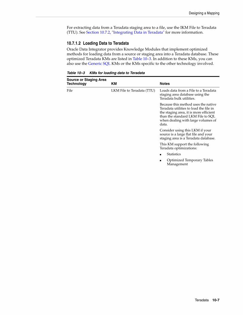
Designing a Mapping
Teradata 10-7
For extracting data from a Teradata staging area to a file, use the IKM File to Teradata (TTU). See Section 10.7.2, "Integrating Data in Teradata" for more information.
10.7.1.2 Loading Data to TeradataOracle Data Integrator provides Knowledge Modules that implement optimized methods for loading data from a source or staging area into a Teradata database. These optimized Teradata KMs are listed in Table 10–3. In addition to these KMs, you can also use the Generic SQL KMs or the KMs specific to the other technology involved.
Table 10–3 KMs for loading data to Teradata
Source or Staging Area Technology KM Notes
File LKM File to Teradata (TTU) Loads data from a File to a Teradata staging area database using the Teradata bulk utilities.
Because this method uses the native Teradata utilities to load the file in the staging area, it is more efficient than the standard LKM File to SQL when dealing with large volumes of data.
Consider using this LKM if your source is a large flat file and your staging area is a Teradata database.
This KM support the following Teradata optimizations:
■ Statistics
■ Optimized Temporary Tables Management

Designing a Mapping
10-8 Oracle Fusion Middleware Connectivity and Knowledge Modules Guide for Oracle Data Integrator
10.7.2 Integrating Data in TeradataOracle Data Integrator provides Knowledge Modules that implement optimized data integration strategies for Teradata. These optimized Teradata KMs are listed in Table 10–4. In addition to these KMs, you can also use the Generic SQL KMs.
The IKM choice in the Integration Knowledge Module tab determines the performances and possibilities for integrating.
SQL LKM SQL to Teradata (TTU) Loads data from a SQL compliant source database to a Teradata staging area database using a native Teradata bulk utility.
This LKM can unload the source data in a file or Named Pipe and then call the specified Teradata utility to populate the staging table from this file/pipe. Using named pipes avoids landing the data in a file. This LKM is recommended for very large volumes.
Consider using this IKM when:
■ The source data located on a SQL compliant database is large
■ You don't want to stage your data between the source and the target
■ Your staging area is a Teradata database.
This KM support the following Teradata optimizations:
■ Support for Teradata Utilities
■ Support for Named Pipes
■ Optimized Temporary Tables Management
Table 10–4 KMs for integrating data to Teradata
KM Notes
IKM Teradata Control Append Integrates data in a Teradata target table in replace/append mode. When flow data needs to be checked using a CKM, this IKM creates a temporary staging table before invoking the CKM.
Consider using this IKM if you plan to load your Teradata target table in replace mode, with or without data integrity check.
To use this IKM, the staging area must be on the same data server as the target Teradata table.
This KM support the following Teradata optimizations:
■ Primary Indexes and Statistics
■ Optimized Temporary Tables Management
Table 10–3 (Cont.) KMs for loading data to Teradata
Source or Staging Area Technology KM Notes

Designing a Mapping
Teradata 10-9
IKM Teradata Incremental Update Integrates data in a Teradata target table in incremental update mode. This IKM creates a temporary staging table to stage the data flow. It then compares its content to the target table to guess which records should be inserted and which others should be updated. It also allows performing data integrity check by invoking the CKM.
Inserts and updates are done in bulk set-based processing to maximize performance. Therefore, this IKM is optimized for large volumes of data.
Consider using this IKM if you plan to load your Teradata target table to insert missing records and to update existing ones.
To use this IKM, the staging area must be on the same data server as the target.
This KM support the following Teradata optimizations:
■ Primary Indexes and Statistics
■ Optimized Temporary Tables Management
IKM Teradata Multi Statement Integrates data in Teradata database target table using multi statement requests, managed in one SQL transaction
IKM Teradata Slowly Changing Dimension
Integrates data in a Teradata target table used as a Type II Slowly Changing Dimension in your Data Warehouse. This IKM relies on the Slowly Changing Dimension metadata set on the target datastore to figure out which records should be inserted as new versions or updated as existing versions.
Because inserts and updates are done in bulk set-based processing, this IKM is optimized for large volumes of data.
Consider using this IKM if you plan to load your Teradata target table as a Type II Slowly Changing Dimension.
To use this IKM, the staging area must be on the same data server as the target and the appropriate Slowly Changing Dimension metadata needs to be set on the target datastore.
This KM support the following Teradata optimizations:
■ Primary Indexes and Statistics
■ Optimized Temporary Tables Management
This KM also includes a COMPATIBLE option. This option corresponds to the Teradata engine major version number. If this version is 12 or above, then a MERGE statement will be used instead of the standard INSERT then UPDATE statements to merge the incoming data flow into the target table.
Table 10–4 (Cont.) KMs for integrating data to Teradata
KM Notes

Designing a Mapping
10-10 Oracle Fusion Middleware Connectivity and Knowledge Modules Guide for Oracle Data Integrator
IKM Teradata to File (TTU) Integrates data in a target file from a Teradata staging area in replace mode. This IKM requires the staging area to be on Teradata. It uses the native Teradata utilities to export the data to the target file.
Consider using this IKM if you plan to transform and export data to a target file from your Teradata server.
To use this IKM, the staging area must be different from the target. It should be set to a Teradata location.
This KM support the following Teradata optimizations:
■ Support for Teradata Utilities
IKM File to Teradata (TTU) This IKM is designed to leverage the power of the Teradata utilities for loading files directly to the target. It is restricted to one file as source and one Teradata table as target.
Depending on the utility you choose, you'll have the ability to integrate the data in either replace or incremental update mode.
Consider using this IKM if you plan to load a single flat file to your target table. Because it uses the Teradata utilities, this IKM is recommended for very large volumes.
To use this IKM, you have to set the staging area to the source file's schema.
This KM support the following Teradata optimizations:
■ Primary Indexes and Statistics
■ Support for Teradata Utilities
■ Optimized Temporary Tables Management.
Table 10–4 (Cont.) KMs for integrating data to Teradata
KM Notes
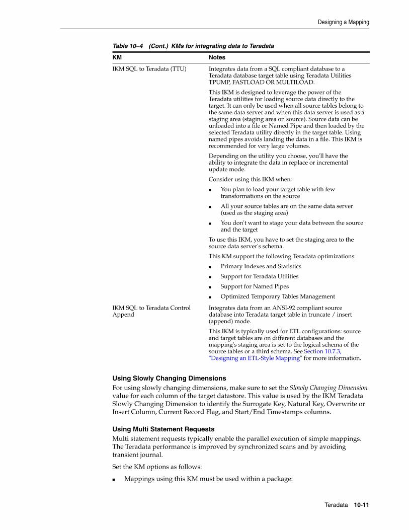
Designing a Mapping
Teradata 10-11
Using Slowly Changing DimensionsFor using slowly changing dimensions, make sure to set the Slowly Changing Dimension value for each column of the target datastore. This value is used by the IKM Teradata Slowly Changing Dimension to identify the Surrogate Key, Natural Key, Overwrite or Insert Column, Current Record Flag, and Start/End Timestamps columns.
Using Multi Statement RequestsMulti statement requests typically enable the parallel execution of simple mappings. The Teradata performance is improved by synchronized scans and by avoiding transient journal.
Set the KM options as follows:
■ Mappings using this KM must be used within a package:
IKM SQL to Teradata (TTU) Integrates data from a SQL compliant database to a Teradata database target table using Teradata Utilities TPUMP, FASTLOAD OR MULTILOAD.
This IKM is designed to leverage the power of the Teradata utilities for loading source data directly to the target. It can only be used when all source tables belong to the same data server and when this data server is used as a staging area (staging area on source). Source data can be unloaded into a file or Named Pipe and then loaded by the selected Teradata utility directly in the target table. Using named pipes avoids landing the data in a file. This IKM is recommended for very large volumes.
Depending on the utility you choose, you'll have the ability to integrate the data in replace or incremental update mode.
Consider using this IKM when:
■ You plan to load your target table with few transformations on the source
■ All your source tables are on the same data server (used as the staging area)
■ You don't want to stage your data between the source and the target
To use this IKM, you have to set the staging area to the source data server's schema.
This KM support the following Teradata optimizations:
■ Primary Indexes and Statistics
■ Support for Teradata Utilities
■ Support for Named Pipes
■ Optimized Temporary Tables Management
IKM SQL to Teradata Control Append
Integrates data from an ANSI-92 compliant source database into Teradata target table in truncate / insert (append) mode.
This IKM is typically used for ETL configurations: source and target tables are on different databases and the mapping's staging area is set to the logical schema of the source tables or a third schema. See Section 10.7.3, "Designing an ETL-Style Mapping" for more information.
Table 10–4 (Cont.) KMs for integrating data to Teradata
KM Notes

Designing a Mapping
10-12 Oracle Fusion Middleware Connectivity and Knowledge Modules Guide for Oracle Data Integrator
– In the first mapping of the package loading a table via the multi-statement set the INIT_MULTI_STATEMENT option to YES.
– The subsequent mappings loading a table via the multi-statement must use this KM and have the INIT_MULTI_STATEMENT option set to NO.
– The last mapping must have the EXECUTE option set to YES in order to run the generated multi-statement.
■ In the STATEMENT_TYPE option, specify the type of statement (insert or update) for each mapping.
■ In the SQL_OPTION option, specify the additional SQL sentence that is added at the end of the query, for example QUALIFY Clause.
Note the following limitations concerning multi-statements:
■ Multi-statements are only supported when they are used within a package.
■ Temporary indexes are not supported.
■ Updates are considered as Inserts in terms of row count.
■ Updates can only have a single Dataset.
■ Only executing mapping (EXECUTE = YES) reports row counts.
■ Journalized source data not supported.
■ Neither Flow Control nor Static Control is supported.
■ The SQL_OPTION option applies only to the last Dataset.
10.7.3 Designing an ETL-Style MappingSee "Creating a Mapping" in the Developer's Guide for Oracle Data Integrator for generic information on how to design mappings. This section describes how to design an ETL-style mapping where the staging area is on a Teradata database or any ANSI-92 compliant database and the target on Teradata.
In an ETL-style mapping, ODI processes the data in a staging area, which is different from the target. Oracle Data Integrator provides two ways for loading the data from a Teradata or an ANSI-92 compliant staging area to a Teradata target:
■ Using a Multi-connection IKM
■ Using an LKM and a mono-connection IKM
Depending on the KM strategy that is used, flow and static control are supported.
Using a Multi-connection IKMA multi-connection IKM allows integrating data into a target when the staging area and sources are on different data servers.
Oracle Data Integrator provides the following multi-connection IKM for handling Teradata data: IKM SQL to Teradata Control Append. You can also use the generic SQL multi-connection IKMs. See Chapter 4, "Generic SQL" for more information.
See Table 10–5 for more information on when to use a multi-connection IKM.
To use a multi-connection IKM in an ETL-style mapping:
1. Create a mapping with an ANSI-92 compliant staging area and the target on Teradata using the standard procedure as described in "Creating a Mapping" in the

Designing a Mapping
Teradata 10-13
Developer's Guide for Oracle Data Integrator. This section describes only the ETL-style specific steps.
2. Change the staging area for the mapping to the logical schema of the source tables or a third schema. See "Configuring Execution Locations" in the Developer's Guide for Oracle Data Integrator for information about how to change the staging area.
3. In the Physical diagram, select an access point. The Property Inspector opens for this object.
4. In the Loading Knowledge Module tab, select an LKM to load from the source(s) to the staging area. See Table 10–5 to determine the LKM you can use.
5. Optionally, modify the KM options.
6. In the Physical diagram, select the Target by clicking its title. The Property Inspector opens for this object.
7. In the Integration Knowledge Module tab, select an ETL multi-connection IKM to load the data from the staging area to the target. See Table 10–5 to determine the IKM you can use.
Note the following when setting the KM options of the IKM SQL to Teradata Control Append:
■ If you do not want to create any tables on the target system, set FLOW_CONTROL=false. If FLOW_CONTROL=false, the data is inserted directly into the target table.
■ If FLOW_CONTROL=true, the flow table is created on the target or on the staging area.
■ If you want to recycle data rejected from a previous control, set RECYCLE_ERROR=true and set an update key for your mapping.
Using an LKM and a mono-connection IKMIf there is no dedicated multi-connection IKM, use a standard exporting LKM in combination with a standard mono-connection IKM. The exporting LKM is used to load the flow table from the staging area to the target. The mono-connection IKM is used to integrate the data flow into the target table.
Oracle Data Integrator supports any ANSI SQL-92 standard compliant technology as a source and staging area of an ETL-style mapping. The target is Teradata.
See Table 10–5 for more information on when to use the combination of a standard LKM and a mono-connection IKM.
To use an LKM and a mono-connection IKM in an ETL-style mapping:
1. Create a mapping with an ANSI-92 compliant staging area and the target on Teradata using the standard procedure as described in "Creating a Mapping" in the Developer's Guide for Oracle Data Integrator. This section describes only the ETL-style specific steps.
2. Change the staging area for the mapping to the logical schema of the source tables or a third schema. See "Configuring Execution Locations" in the Developer's Guide for Oracle Data Integrator for information about how to change the staging area.
3. In the Physical diagram, select an access point. The Property Inspector opens for this object.
4. In the Loading Knowledge Module tab, select an LKM to load from the source(s) to the staging area. See Table 10–5 to determine the LKM you can use.

Designing a Mapping
10-14 Oracle Fusion Middleware Connectivity and Knowledge Modules Guide for Oracle Data Integrator
5. Optionally, modify the KM options.
6. Select the access point for the Staging Area. The Property Inspector opens for this object.
7. In the Loading Knowledge Module tab, select an LKM to load from the staging area to the target. See Table 10–5 to determine the LKM you can use.
8. Optionally, modify the options.
9. Select the Target by clicking its title. The Property Inspector opens for this object.
In the Integration Knowledge Module tab, select a standard mono-connection IKM to update the target. See Table 10–5 to determine the IKM you can use.
Table 10–5 KM Guidelines for ETL-Style Mappings with Teradata Data
Source Staging Area TargetExporting LKM IKM KM Strategy Comment
ANSI SQL-92 standard compliant
ANSI SQL-92 standard compliant
Teradata NA IKM SQL to Teradata Control Append
Multi-connection IKM
Recommended to perform control append
Supports flow control.
ANSI SQL-92 standard compliant
Teradata or any ANSI SQL-92 standard compliant database
Teradata or any ANSI SQL-92 standard compliant database
NA IKM SQL to SQL Incremental Update
Multi-connection IKM
Allows an incremental update strategy with no temporary target-side objects. Use this KM if it is not possible to create temporary objects in the target server.
The application updates are made without temporary objects on the target, the updates are made directly from source to target. The configuration where the flow table is created on the staging area and not in the target should be used only for small volumes of data.
Supports flow and static control

KM Optimizations for Teradata
Teradata 10-15
10.8 KM Optimizations for TeradataThis section describes the specific optimizations for Teradata that are included in the Oracle Data Integrator Knowledge Modules.
This section includes the following topics:
■ Primary Indexes and Statistics
■ Support for Teradata Utilities
■ Support for Named Pipes
■ Optimized Management of Temporary Tables
10.8.1 Primary Indexes and StatisticsTeradata performance heavily relies on primary indexes. The Teradata KMs support customized primary indexes (PI) for temporary and target tables. This applies to Teradata LKMs, IKMs and CKMs. The primary index for the temporary and target tables can be defined in these KMs using the PRIMARY_INDEX KM option, which takes the following values:
■ [PK]: The PI will be the primary key of each temporary or target table. This is the default value.
■ [NOPI]: Do not specify primary index (Teradata 13.0 & above only).
■ [UK]: The PI will be the update key of the mapping. This is the default value.
– <Column list>: This is a free PI based on the comma-separated list of column names.
– <Empty string>: No primary index is specified. The Teradata engine will use the default rule for the PI (first column of the temporary table).
Teradata MultiColumnStatistics should optionally be gathered for selected PI columns. This is controlled by COLLECT_STATS KM option, which is set to true by default.
ANSI SQL-92 standard compliant
Teradata or ANSI SQL-92 standard compliant
Teradata LKM SQL to Teradata (TTU)
IKM Teradata Incremental Update
LKM + standard IKM
ANSI SQL-92 standard compliant
Teradata Teradata LKM SQL to Teradata (TTU)
IKM Teradata Slowly Changing Dimension
LKM + standard IKM
ANSI SQL-92 standard compliant
ANSI SQL-92 standard compliant
Teradata LKM SQL to Teradata (TTU)
IKM SQL to Teradata (TTU)
LKM + standard IKM
If no flow control, this strategy is recommended for large volumes of data
Table 10–5 (Cont.) KM Guidelines for ETL-Style Mappings with Teradata Data
Source Staging Area TargetExporting LKM IKM KM Strategy Comment

KM Optimizations for Teradata
10-16 Oracle Fusion Middleware Connectivity and Knowledge Modules Guide for Oracle Data Integrator
10.8.2 Support for Teradata UtilitiesTeradata Utilities (TTU) provide an efficient method for transferring data from and to the Teradata engine. When using a LKM or IKM supporting TTUs, it is possible to set the method for loading data using the TERADATA_UTILITY option.
This option takes the following values when pushing data to a Teradata target (IKM) or staging area (LKM):
■ FASTLOAD: use Teradata FastLoad
■ MLOAD: use Teradata MultiLoad
■ TPUMP: use Teradata TPump
■ TPT-LOAD: use Teradata Parallel Transporter (Load Operator)
■ TPT-SQL-INSERT: use Teradata Parallel Transporter (SQL Insert Operator)
This option takes the following values when pushing data FROM Teradata to a file:
■ FEXP: use Teradata FastExport
■ TPT: use Teradata Parallel Transporter
When using TTU KMs, you should also take into account the following KM parameters:
■ REPORT_NB_ROWS: This option allows you to report the number of lines processed by the utility in a Warning step of the mapping.
■ SESSIONS: Number of FastLoad sessions
■ MAX_ALLOWED_ERRORS: Maximum number of tolerated errors. This corresponds to the ERRLIMIT command in FastLoad/MultiLoad/TPump and to the ErrorLimit attribute for TPT.
■ MULTILOAD_TPUMP_TYPE: Operation performed by the MultiLoad or TPump utility. Valid values are INSERT, UPSERT and DELETE. For UPSERT and DELETE an update key is required in the mapping.
For details and appropriate choice of utility and load operator, refer to the Teradata documentation.
10.8.3 Support for Named PipesWhen using TTU KMs to move data between a SQL source and Teradata, it is possible to increase the performances by using Named Pipes instead of files between the unload/load processes. Named Pipes can be activated by setting the NP_USE_NAMED_PIPE option to YES. The following options should also be taken into account for using Named Pipes:
■ NP_EXEC_ON_WINDOWS: Set this option to YES if the run-time agent runs on a windows platform.
■ NP_ACCESS_MODULE: Access module used for Named Pipes. This access module is platform dependant.
■ NP_TTU_STARTUP_TIME: This number of seconds for the TTU to be able to receive data through the pipe. This is the delay between the moment the KM starts the TTU and the moment the KM starts to push data into the named pipe. This delay is dependant on the machine workload.

KM Optimizations for Teradata
Teradata 10-17
10.8.4 Optimized Management of Temporary Tables Creating and dropping Data Integrator temporary staging tables can be a resource consuming process on a Teradata engine. The ODI_DDL KM option provides a mean to control these DDL operations. It takes the following values:
■ DROP_CREATE: Always drop and recreate all temporary tables for every execution (default behavior).
■ CREATE_DELETE_ALL: Create temporary tables when needed (usually for the first execution only) and use DELETE ALL to drop the temporary table content. Temporary table are reused for subsequent executions.
■ DELETE_ALL: Do not create temporary tables. Only submit DELETE ALL for all temporary tables.
■ NONE: Do not issue any DDL on temporary tables. Temporary tables should be handled separately.

KM Optimizations for Teradata
10-18 Oracle Fusion Middleware Connectivity and Knowledge Modules Guide for Oracle Data Integrator

11
IBM DB2 for iSeries 11-1
11IBM DB2 for iSeries
This chapter describes how to work with IBM DB2 for iSeries in Oracle Data Integrator.
This chapter includes the following sections:
■ Section 11.1, "Introduction"
■ Section 11.2, "Installation and Configuration"
■ Section 11.3, "Setting up the Topology"
■ Section 11.4, "Setting Up an Integration Project"
■ Section 11.5, "Creating and Reverse-Engineering an IBM DB2/400 Model"
■ Section 11.6, "Setting up Changed Data Capture"
■ Section 11.7, "Setting up Data Quality"
■ Section 11.8, "Designing a Mapping"
■ Section 11.9, "Specific Considerations with DB2 for iSeries"
■ Section 11.10, "Troubleshooting"
11.1 IntroductionOracle Data Integrator (ODI) seamlessly integrates data in IBM DB2 for iSeries. Oracle Data Integrator features are designed to work best with IBM DB2 for iSeries, including reverse-engineering, changed data capture, data integrity check, and mappings.
11.1.1 ConceptsThe IBM DB2 for iSeries concepts map the Oracle Data Integrator concepts as follows: An IBM DB2 for iSeries server corresponds to a data server in Oracle Data Integrator. Within this server, a collection or schema maps to an Oracle Data Integrator physical schema. A set of related objects within one schema corresponds to a data model, and each table, view or synonym will appear as an ODI datastore, with its attributes, columns and constraints.
Oracle Data Integrator uses Java Database Connectivity (JDBC) to connect to IBM DB2 for iSeries.
11.1.2 Knowledge ModulesOracle Data Integrator provides the Knowledge Modules (KM) listed in Table 11–1 for handling IBM DB2 for iSeries data. In addition to these specific IBM DB2 for iSeries

Installation and Configuration
11-2 Oracle Fusion Middleware Connectivity and Knowledge Modules Guide for Oracle Data Integrator
Knowledge Modules, it is also possible to use the generic SQL KMs with IBM DB2 for iSeries. See Chapter 4, "Generic SQL" for more information.
11.2 Installation and ConfigurationMake sure you have read the information in this section before you start working with the IBM DB2 for iSeries technology:
■ System Requirements and Certifications
■ Technology Specific Requirements
■ Connectivity Requirements
11.2.1 System Requirements and CertificationsBefore performing any installation you should read the system requirements and certification documentation to ensure that your environment meets the minimum installation requirements for the products you are installing.
The list of supported platforms and versions is available on Oracle Technical Network (OTN):
http://www.oracle.com/technology/products/oracle-data-integrator/index.html.
Table 11–1 IBM DB2 for iSeries Knowledge Modules
Knowledge Module Description
IKM DB2 400 Incremental Update Integrates data in an IBM DB2 for iSeries target table in incremental update mode.
IKM DB2 400 Incremental Update (CPYF) Integrates data in an IBM DB2 for iSeries target table in incremental update mode. This IKM is similar to the "IKM DB2 400 Incremental Update" except that it uses the CPYF native OS/400 command to write to the target table, instead of set-based SQL operations.
IKM DB2 400 Slowly Changing Dimension Integrates data in an IBM DB2 for iSeries target table used as a Type II Slowly Changing Dimension in your Data Warehouse.
JKM DB2 400 Consistent Creates the journalizing infrastructure for consistent journalizing on IBM DB2 for iSeries tables using triggers.
JKM DB2 400 Simple Creates the journalizing infrastructure for simple journalizing on IBM DB2 for iSeries tables using triggers.
JKM DB2 400 Simple (Journal) Creates the journalizing infrastructure for simple journalizing on IBM DB2 for iSeries tables using the journals.
LKM DB2 400 Journal to SQL Loads data from an IBM DB2 for iSeries source to a ANSI SQL-92 compliant staging area database. This LKM can source from tables journalized with the JKM DB2 400 Simple (Journal) as it refreshes the CDC infrastructure from the journals.
LKM DB2 400 to DB2 400 Loads data from an IBM DB2 for iSeries source database to an IBM DB2 for iSeries staging area database using CRTDDMF to create a DDM file on the target and transfer data from the source to this DDM file using CPYF.
LKM SQL to DB2 400 (CPYFRMIMPF) Loads data from an ANSI SQL-92 compliant source database to an IBM DB2 for iSeries staging area database using a temporary file loaded into the DB2 staging area with CPYFRMIPF.
RKM DB2 400 Retrieves metadata for IBM DB2 for iSeries: physical files, tables, views, foreign keys, unique keys.

Setting up the Topology
IBM DB2 for iSeries 11-3
11.2.2 Technology Specific RequirementsSome of the Knowledge Modules for IBM DB2 for iSeries use specific features of this database. The following restrictions apply when using these Knowledge Modules.
See the IBM DB2 for iSeries documentation for additional information on these topics.
Using System commandsThis section describes the requirements that must be met before using iSeries specific commands in the knowledge modules for IBM DB2 for iSeries:
■ Knowledge modules using system commands such as CPYF or CPYFRMIPF require that the agent runs on the iSeries runs on the iSeries system.
Using CDC with JournalsThis section describes the requirements that must be met before using the Journal-based Change Data Capture with IBM DB2 for iSeries:
■ This journalizing method requires that a specific program is installed and runs on the iSeries system. See Setting up Changed Data Capture for more information.
11.2.3 Connectivity RequirementsThis section lists the requirements for connecting to an IBM DB2 for iSeries system.
JDBC DriverOracle Data Integrator is installed with a default IBM DB2 Datadirect Driver. This driver directly uses the TCP/IP network layer and requires no other installed component or configuration. You can alternatively use the drivers provided by IBM, such as the Native Driver when installing the agent on iSeries.
11.3 Setting up the TopologySetting up the Topology consists of:
1. Creating a DB2/400 Data Server
2. Creating a DB2/400 Physical Schema
11.3.1 Creating a DB2/400 Data ServerAn IBM DB2/400 data server corresponds to an iSeries server connected with a specific user account. This user will have access to several databases in this server, corresponding to the physical schemas in Oracle Data Integrator created under the data server.
11.3.1.1 Creation of the Data ServerCreate a data server for the IBM DB2/400 technology using the standard procedure, as described in "Creating a Data Server" of the Developer's Guide for Oracle Data Integrator. This section details only the fields required or specific for defining an IBM DB2/400 data server:
1. In the Definition tab:
■ Name: Name of the data server that will appear in Oracle Data Integrator
■ Host (Data Server): Name or IP address of the host

Setting Up an Integration Project
11-4 Oracle Fusion Middleware Connectivity and Knowledge Modules Guide for Oracle Data Integrator
■ User/Password: DB2 user with its password
2. In the JDBC tab:
■ JDBC Driver: weblogic.jdbc.db2.DB2Driver
■ JDBC URL: jdbc:as400://<host>[;libraries=<library>][;<property>=<value>...]
The URL parameters are:
– <host>: server network name or IP address
– <library>: default library or collection to access
– <property>=<value>: connection properties. Refer to the driver's documentation for a list of available properties.
11.3.2 Creating a DB2/400 Physical SchemaCreate an IBM DB2/400 physical schema using the standard procedure, as described in "Creating a Physical Schema" of the Developer's Guide for Oracle Data Integrator.
The work schema and data schema in this physical schema correspond each to a schema (collection or library). The work schema should point to a temporary schema and the data schema should point to the schema hosting the data to integrate.
Create for this physical schema a logical schema using the standard procedure, as described in "Creating a Logical Schema" of the Developer's Guide for Oracle Data Integrator and associate it in a given context.
11.4 Setting Up an Integration ProjectSetting up a project using the IBM DB2 for iSeries database follows the standard procedure. See "Creating an Integration Project" of the Developer's Guide for Oracle Data Integrator.
It is recommended to import the following knowledge modules into your project for getting started with IBM DB2 for iSeries:
■ IKM DB2 400 Incremental Update
■ IKM DB2 400 Slowly Changing Dimension
■ JKM DB2 400 Consistent
■ JKM DB2 400 Simple
■ RKM DB2 400
■ CKM SQL
11.5 Creating and Reverse-Engineering an IBM DB2/400 ModelThis section contains the following topics:
■ Create an IBM DB2/400 Model
■ Reverse-engineer an IBM DB2/400 Model

Setting up Changed Data Capture
IBM DB2 for iSeries 11-5
11.5.1 Create an IBM DB2/400 ModelCreate an IBM DB2/400 Model using the standard procedure, as described in "Creating a Model" of the Developer's Guide for Oracle Data Integrator.
11.5.2 Reverse-engineer an IBM DB2/400 ModelIBM DB2 for iSeries supports both Standard reverse-engineering - which uses only the abilities of the JDBC driver - and Customized reverse-engineering, which uses a RKM to retrieve the metadata.
In most of the cases, consider using the standard JDBC reverse engineering for starting.
Consider switching to customized reverse-engineering for retrieving more metadata. IBM DB2 for iSeries customized reverse-engineering retrieves the physical files, database tables, database views, columns, foreign keys and primary and alternate keys.
Standard Reverse-EngineeringTo perform a Standard Reverse-Engineering on IBM DB2 for iSeries use the usual procedure, as described in "Reverse-engineering a Model" of the Developer's Guide for Oracle Data Integrator.
Customized Reverse-EngineeringTo perform a Customized Reverse-Engineering on IBM DB2 for iSeries with a RKM, use the usual procedure, as described in "Reverse-engineering a Model" of the Developer's Guide for Oracle Data Integrator. This section details only the fields specific to the IBM DB2/400 technology:
In the Reverse tab of the IBM DB2/400 Model, select the KM: RKM DB2 400.<project name>.
11.6 Setting up Changed Data CaptureOracle Data Integrator handles Changed Data Capture on iSeries with two methods:
■ Trigger-based CDC on the journalized tables. This method is set up with the JKM DB2/400 Simple or JKM DB2/400 Consistent. This CDC is not different from the CDC on other systems. See Section 11.6.1, "Setting up Trigger-Based CDC" for more information.
■ Log-based CDC by reading the native iSeries transaction journals. This method is set up with the JKM DB2/400 Journal Simple and used by the LKM DB2/400 Journal to SQL. This method does not support Consistent Set CDC and requires a platform-specific configuration. See Section 11.6.1, "Setting up Trigger-Based CDC" for more information.
11.6.1 Setting up Trigger-Based CDCThis method support Simple Journalizing and Consistent Set Journalizing. The IBM DB2 for iSeries JKMs use triggers to capture data changes on the source tables.
Oracle Data Integrator provides the Knowledge Modules listed in Table 11–2 for journalizing IBM DB2 for iSeries tables using triggers.
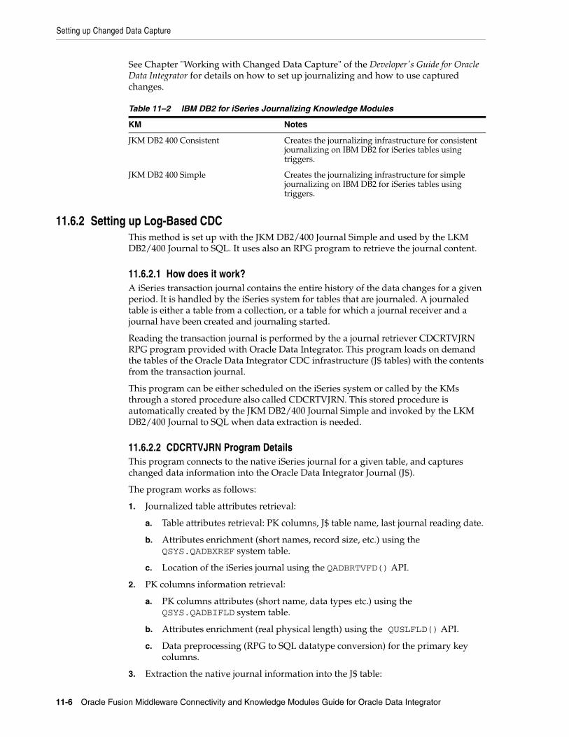
Setting up Changed Data Capture
11-6 Oracle Fusion Middleware Connectivity and Knowledge Modules Guide for Oracle Data Integrator
See Chapter "Working with Changed Data Capture" of the Developer's Guide for Oracle Data Integrator for details on how to set up journalizing and how to use captured changes.
11.6.2 Setting up Log-Based CDCThis method is set up with the JKM DB2/400 Journal Simple and used by the LKM DB2/400 Journal to SQL. It uses also an RPG program to retrieve the journal content.
11.6.2.1 How does it work?A iSeries transaction journal contains the entire history of the data changes for a given period. It is handled by the iSeries system for tables that are journaled. A journaled table is either a table from a collection, or a table for which a journal receiver and a journal have been created and journaling started.
Reading the transaction journal is performed by the a journal retriever CDCRTVJRN RPG program provided with Oracle Data Integrator. This program loads on demand the tables of the Oracle Data Integrator CDC infrastructure (J$ tables) with the contents from the transaction journal.
This program can be either scheduled on the iSeries system or called by the KMs through a stored procedure also called CDCRTVJRN. This stored procedure is automatically created by the JKM DB2/400 Journal Simple and invoked by the LKM DB2/400 Journal to SQL when data extraction is needed.
11.6.2.2 CDCRTVJRN Program DetailsThis program connects to the native iSeries journal for a given table, and captures changed data information into the Oracle Data Integrator Journal (J$).
The program works as follows:
1. Journalized table attributes retrieval:
a. Table attributes retrieval: PK columns, J$ table name, last journal reading date.
b. Attributes enrichment (short names, record size, etc.) using the QSYS.QADBXREF system table.
c. Location of the iSeries journal using the QADBRTVFD() API.
2. PK columns information retrieval:
a. PK columns attributes (short name, data types etc.) using the QSYS.QADBIFLD system table.
b. Attributes enrichment (real physical length) using the QUSLFLD() API.
c. Data preprocessing (RPG to SQL datatype conversion) for the primary key columns.
3. Extraction the native journal information into the J$ table:
Table 11–2 IBM DB2 for iSeries Journalizing Knowledge Modules
KM Notes
JKM DB2 400 Consistent Creates the journalizing infrastructure for consistent journalizing on IBM DB2 for iSeries tables using triggers.
JKM DB2 400 Simple Creates the journalizing infrastructure for simple journalizing on IBM DB2 for iSeries tables using triggers.

Setting up Changed Data Capture
IBM DB2 for iSeries 11-7
a. Native journal reading using the QJoRetrieveJournalEntries() API.
b. Conversion of the raw data to native SQL data and capture into the J$ table.
c. Update of the changes count.
This program accepts the parameters listed in Table 11–3.
11.6.2.3 Installing the CDC Components on iSeriesThere are two major components installed on the iSeries system to enable native journal reading:
■ The CDCRTVJRN Program. This program is provided in an archive that should installed in the iSeries system. The installation process is described below.
■ The CDC Infrastructure. It includes the standard CDC objects (J$ tables, views, ...) and the CDCRTVJRN Stored Procedure created by the JKM and used by the LKM to read journals. This stored procedure executes the CDCRTVJRN program.
Installing the CDCRTVJRN ProgramTo install the CDCRTVJRN program:
1. Identify the location the program SAVF file. It is located in the ODI_HOME/setup/manual/cdc-iseries directory, and is also available on the Oracle Data Integrator Companion CD.
2. Connect to the iSeries system.
3. Create the default work library if it does not exist yet. You can use, for example, the following command to create an ODILIB library:
CRTLIB LIB(ODILIB)
4. Create in this library an empty save file that has the same name as the SAVF file (mandatory). For example:
CRTSAVF FILE(ODILIB/SAVPGM0110)
Table 11–3 CDCRTVJRN Program Parameters
Parameter RPG Type SQL Type Description
SbsTName A138 Char(138) Full name of the subscribers table in the following format: <Lib>.<Table>.
Example: ODILIB.SNP_SUBSCRIBERS
JrnTName A138 Char(138) Full name of the table for which the extract is done from the journal.
Example: FINANCE.MY_COMPANY_ORDERS
JrnSubscriber A50 Char(50) Name of the current subscriber. It must previously have been added to the list of subscribers.
LogMessages A1 Char(1) Flag activating logging in a spool file. Possible values are: Y enable logging, and N to disable logging.
Note: The program must be set up in a library defined in the Topology as the default work library for this iSeries data server. In the examples below, this library is called ODILIB.

Setting up Changed Data Capture
11-8 Oracle Fusion Middleware Connectivity and Knowledge Modules Guide for Oracle Data Integrator
5. Upload the local SAVF file on the iSeries system in the library and on top of the file you have just created. Make sure that the upload process is performed in binary mode.
An FTP command sequence performing the upload is given below as an example.
FTP 192.168.0.13LCD /oracle/odi/setup/manual/cdc-iseries/BICD ODILIBPUT SAVPGM0110 BYE
■ Restore the objects from the save file, using the RSTOBJ command. For example:
RSTOBJ OBJ(*ALL) SAVLIB(CDCSNPRELE) DEV(*SAVF) OBJTYPE(*ALL) SAVF(ODILIB/SAVPGM0110) RSTLIB(ODILIB)
■ Check that the objects are correctly restored. The target library should contain a program object called CDCRTVJRN.
Use the following command below to view it:
WRKOBJ OBJ(ODILIB/CDCRTVJRN)
The CDCRTVJRN Stored ProcedureThis procedure is used to call the CDCRTVJRN program. It is automatically created by the JKM DB2/400 Journal Simple KM when journalizing is started. Journalizing startup is described in the Change Data Capture topic.
The syntax for the stored procedure is provided below for reference:
create procedure ODILIB.CDCRTVJRN( SbsTName char(138), /* Qualified Subscriber Table Name */ JrnTName char(138), /* Qualified Table Name */ Subscriber char(50) , /* Subscriber Name */ LogMessages char(1) /* Create a Log (Y - Yes, N - No) */)language rpgleexternal name 'ODILIB/CDCRTVJRN'
11.6.2.4 Using the CDC with the Native JournalsOnce the program is installed and the CDC is setup, using the native journals consists in using the LKM DB2/400 Journal to SQL to extract journalized data from the iSeries system. The retrieval process is triggered if the RETRIEVE_JOURNAL_ENTRIES option is set to true for the LKM.
11.6.2.5 Problems While Reading JournalsThis section list the possibly issues when using this changed data capture method.
CDCRTVJRN Program LimitsThe following limits exist for the CDCRTVJRN program:
Note: The stored procedure and the program are installed in a library defined in the Topology as the default work library for this iSeries data server

Designing a Mapping
IBM DB2 for iSeries 11-9
■ The source table should be journaled and the iSeries journal should be readable by the user specified in the iSeries data server.
■ The source table should have one PK defined in Oracle Data Integrator.
■ The PK declared in Oracle Data Integrator should be in the 4096 first octets of the physical record of the data file.
■ The number of columns in the PK should not exceed 16.
■ The total number of characters of the PK column names added to the number of columns of the PK should not exceed 255.
■ Large object datatypes are not supported in the PK. Only the following SQL types are supported in the PK: SMALLINT, INTEGER, BIGINT, DECIMAL (Packed), NUMERIC (Zoned), FLOAT, REAL, DOUBLE, CHAR, VARCHAR, CHAR VARYING, DATE, TIME, TIMESTAMP and ROWID.
■ Several instances of CDCRTVJRN should not be started simultaneously on the same system.
■ Reinitializing the sequence number in the iSeries journal may have a critical impact on the program (program hangs) if the journal entries consumption date (SNP_SUBSCRIBERS.JRN_CURFROMDATE) is before the sequence initialization date. To work around this problem, you should manually set a later date in SNP_SUBSCRIBERS.JRN_CURFROMDATE.
Troubleshooting the CDCRTVJRN ProgramThe journal reading process can be put in trace mode:
■ either by calling from your query tool the CDCRTVJRN stored procedure with the LogMsg parameter set to Y,
■ or by forcing the CREATE_SPOOL_FILE LKM option to 1 then restarting the mapping.
The reading process logs are stored in a spool file which can be reviewed using the WRKSPLF command.
You can also review the raw contents of the iSeries journal using the DSPJRN command.
11.7 Setting up Data QualityOracle Data Integrator provides the generic CKM SQL for checking data integrity against constraints defined in DB2/400. See "Set up Flow Control and Post-Integration Control" in the Developer's Guide for Oracle Data Integrator for details.
See Chapter 4, "Generic SQL" for more information.
11.8 Designing a MappingYou can use IBM DB2 for iSeries as a source, staging area or a target of a mapping.
The KM choice for a mapping or a check determines the abilities and performance of this mapping or check. The recommendations in this section help in the selection of the KM for different situations concerning an IBM DB2 for iSeries data server.

Designing a Mapping
11-10 Oracle Fusion Middleware Connectivity and Knowledge Modules Guide for Oracle Data Integrator
11.8.1 Loading Data from and to IBM DB2 for iSeries IBM DB2 for iSeries can be used as a source, target or staging area of a mapping. The LKM choice in the Mapping Flow tab to load data between IBM DB2 for iSeries and another type of data server is essential for the performance of a mapping.
11.8.1.1 Loading Data from IBM DB2 for iSeries Oracle Data Integrator provides Knowledge Modules that implement optimized methods for loading data from IBM DB2 for iSeries to a target or staging area database. These optimized IBM DB2 for iSeries KMs are listed in Table 11–4.
In addition to these KMs, you can also use the Generic SQL KMs or the KMs specific to the other technology involved to load data from IBM DB2 for iSeries to a target or staging area database.
11.8.1.2 Loading Data to IBM DB2 for iSeries Oracle Data Integrator provides Knowledge Modules that implement optimized methods for loading data from a source or staging area into an IBM DB2 for iSeries database. These optimized IBM DB2 for iSeries KMs are listed in Table 11–5.
In addition to these KMs, you can also use the Generic SQL KMs or the KMs specific to the other technology involved.
Table 11–4 KMs for loading data from IBM DB2 for iSeries
Source or Staging Area Technology KM Notes
IBM DB2 for iSeries LKM DB2 400 to DB2 400 Loads data from an IBM DB2 for iSeries source database to an IBM DB2 for iSeries staging area database using CRTDDMF to create a DDM file on the target and transfer data from the source to this DDM file using CPYF.
IBM DB2 for iSeries LKM DB2 400 Journal to SQL
Loads data from an IBM DB2 for iSeries source to a ANSI SQL-92 compliant staging area database. This LKM can source from tables journalized with the JKM DB2 400 Simple (Journal) as it refreshes the CDC infrastructure from the journals.
Table 11–5 KMs for loading data to IBM DB2 for iSeries
Source or Staging Area Technology KM Notes
IBM DB2 for iSeries LKM DB2 400 to DB2 400 Loads data from an IBM DB2 for iSeries source database to an IBM DB2 for iSeries staging area database using CRTDDMF to create a DDM file on the target and transfer data from the source to this DDM file using CPYF.
SQL LKM SQL to DB2 400 (CPYFRMIMPF)
Loads data from an ANSI SQL-92 compliant source database to an IBM DB2 for iSeries staging area database using a temporary file loaded into the DB2 staging area with CPYFRMIPF.

Specific Considerations with DB2 for iSeries
IBM DB2 for iSeries 11-11
11.8.2 Integrating Data in IBM DB2 for iSeries Oracle Data Integrator provides Knowledge Modules that implement optimized data integration strategies for IBM DB2 for iSeries. These optimized IBM DB2 for iSeries KMs are listed in Table 11–6. I
In addition to these KMs, you can also use the Generic SQL KMs.
The IKM choice in the Mapping Flow tab determines the performances and possibilities for integrating.
Using Slowly Changing DimensionsFor using slowly changing dimensions, make sure to set the Slowly Changing Dimension value for each attributes of the target datastore. This value is used by the IKM DB2 400 Slowly Changing Dimension to identify the Surrogate Key, Natural Key, Overwrite or Insert Column, Current Record Flag and Start/End Timestamps columns.
11.9 Specific Considerations with DB2 for iSeriesThis section provides specific considerations when using Oracle Data Integrator in an iSeries environment.
11.9.1 Installing the Run-Time Agent on iSeriesThe Oracle Data Integrator Standalone Agent can be installed on iSeries.
See the Installing and Configuring Oracle Data Integrator for more information.
11.9.2 Alternative Connectivity Methods for iSeriesIt is preferable to use the built-in IBM DB2 Datadirect driver in most cases. This driver directly use the TCP/IP network layer and require no other components installed on the client machine. Other methods exist to connect DB2 on iSeries.
11.9.2.1 Using Client AccessIt is also possible to connect through ODBC with the IBM Client Access component installed on the machine. This method does not have very good performance and does not support the reverse engineering and some other features. It is therefore not recommended.
Table 11–6 KMs for integrating data to IBM DB2 for iSeries
KM Notes
IKM DB2 400 Incremental Update Integrates data in an IBM DB2 for iSeries target table in incremental update mode.
IKM DB2 400 Incremental Update (CPYF)
Integrates data in an IBM DB2 for iSeries target table in incremental update mode. This IKM is similar to the "IKM DB2 400 Incremental Update" except that it uses the CPYF native OS/400 command to write to the target table, instead of set-based SQL operations.
IKM DB2 400 Slowly Changing Dimension
Integrates data in an IBM DB2 for iSeries target table used as a Type II Slowly Changing Dimension in your Data Warehouse.

Troubleshooting
11-12 Oracle Fusion Middleware Connectivity and Knowledge Modules Guide for Oracle Data Integrator
11.9.2.2 Using the IBM JT/400 and Native DriversThis driver appears as a jt400.zip file you must copy into your Oracle Data Integrator installation drivers directory.
To connect DB2 for iSeries with a Java application installed on the iSeries machine, IBM recommends that you use the JT/400 Native driver (jt400native.jar) instead of the JT/400 driver (jt400.jar). The Native driver provides optimized access to the DB2 system, but works only from the iSeries machine.
To support seamlessly both drivers with one connection, Oracle Data Integrator has a built-in Driver Wrapper for AS/400. This wrapper connects through the Native driver if possible, otherwise it uses the JT/400 driver. It is recommended that you use this wrapper if running agents installed on AS/400 systems.
To configure a data server with the driver wrapper:
1. Change the driver and URL to your AS/400 server with the following information:
■ Driver: com.sunopsis.jdbc.driver.wrapper.SnpsDriverWrapper
■ URL: jdbc:snps400:<machine_name>[;param1=value1[;param2=value2...]]
2. Set the following java properties for the java machine the run-time agent deployed on iSeries:
■ HOST_NAME: comma separated list of host names identifying the current machine.
■ HOST_IP: IP Address of the current machine.
The value allow the wrapper to identify whether this data server is accessed on the iSeries machine or from a remote machine.
11.10 TroubleshootingThis section provides information on how to troubleshoot problems that you might encounter when using Oracle Knowledge Modules. It contains the following topics:
■ Troubleshooting Error messages
■ Common Problems and Solutions
11.10.1 Troubleshooting Error messagesErrors in Oracle Data Integrator appear often in the following way:
java.sql.SQLException: The application server rejected the connection.(Signon was canceled.)at ...at ......
the java.sql.SQLExceptioncode simply indicates that a query was made to the database through the JDBC driver, which has returned an error. This error is frequently a database or driver error, and must be interpreted in this direction.
Only the part of text in bold must first be taken in account. It must be searched in the DB2 or iSeries documentation. If its contains sometimes an error code specific to your system, with which the error can be immediately identified.

Troubleshooting
IBM DB2 for iSeries 11-13
If such an error is identified in the execution log, it is necessary to analyze the SQL code send to the database to find the source of the error. The code is displayed in the description tab of the erroneous task.
11.10.2 Common Problems and SolutionsThis section describes common problems and solutions.
11.10.2.1 Connection Errors■ UnknownDriverException
The JDBC driver is incorrect. Check the name of the driver.
■ The application requester cannot establish the connection.(<name or IP address>) Cannot open a socket on host: <name or IP address>, port: 8471 (Exception: java.net.UnknownHostException:<name or IP address>)
Oracle Data Integrator cannot connect to the database. Either the machine name or IP address is invalid, the DB2/400 Services are not started or the TCP/IP interface on AS/400 is not started. Try to ping the AS/400 machine using the same machine name or IP address, and check with the system administrator that the appropriate services are started.
■ Datasource not found or driver name not specified
The ODBC Datasource specified in the JDBC URL is incorrect.
■ The application server rejected the connection.(Signon was canceled.) Database login failed, please verify userid and password. Communication Link Failure. Comm RC=8001 - CWBSY0001 - ...
The user profile used is not valid. This error occurs when typing an invalid user name or an incorrect password.
■ Communication Link Failure
An error occurred with the ODBC connectivity. Refer to the Client Access documentation for more information.
■ SQL5001 - Column qualifier or table &2 undefined. SQL5016 - Object name &1 not valid for naming convention
Your JDBC connection or ODBC Datasource is configured to use the wrong naming convention. Use the ODBC Administrator to change your datasource to use the proper (*SQL or *SYS) naming convention, or use the appropriate option in the JDBC URL to force the naming conversion (for instance jdbc:as400://195.10.10.13;naming=system) . Note that if using the system naming convention in the Local Object Mask of the Physical Schema, you must enter %SCHEMA/%OBJECT instead of %SCHEMA.%OBJECT.
"*SQL" should always be used unless your application is specifically designed for *SYS. Oracle Data Integrator uses the *SQL naming convention by default.
■ SQL0204 &1 in &2 type *&3 not found
The table you are trying to access does not exist. This may be linked to an error in the context choice, or in the sequence of operations (E.g.: The table is a temporary table which must be created by another mapping).
Troubleshooting
11-14 Oracle Fusion Middleware Connectivity and Knowledge Modules Guide for Oracle Data Integrator
■ Hexadecimal characters appear in the target tables. Accentuated characters are incorrectly transferred.
The iSeries computer attaches a language identifier or CCSID to files, tables and even fields (columns). CCSID 65535 is a generic code that identifies a file or field as being language independent: i.e. hexadecimal data. By definition, no translation is performed by the drivers. If you do not wish to update the CCSID of the file, then translation can be forced, in the JDBC URL, thanks to the flags ccsid=<ccsid code> and convert _ccsid_65535=yes|no. See the driver's documentation for more information.
■ SQL0901 SQL system error
This error is an internal error of the DB2/400 system.
■ SQL0206 Column &1 not in specified tables
Keying error in a mapping/join/filter. A string which is not a column name is interpreted as a column name, or a column name is misspelled.
This error may also appear when accessing an error table associated to a datastore with a structure recently modified. It is necessary to impact in the error table the modification, or drop the error tables and let Oracle Data Integrator recreate it in the next execution.
12
IBM DB2 UDB 12-1
12IBM DB2 UDB
This chapter describes how to work with IBM DB2 UDB in Oracle Data Integrator.
This chapter includes the following sections:
■ Section 12.1, "Introduction"
■ Section 12.2, "Concepts"
■ Section 12.3, "Knowledge Modules"
■ Section 12.4, "Specific Requirements"
12.1 IntroductionOracle Data Integrator (ODI) seamlessly integrates data in an IBM DB2 UDB database. Oracle Data Integrator features are designed to work best with IBM DB2 UDB, including journalizing, data integrity checks, and mappings.
12.2 ConceptsThe IBM DB2 UDB concepts map the Oracle Data Integrator concepts as follows: An IBM DB2 UDB database corresponds to a data server in Oracle Data Integrator. Within this server, a schema maps to an Oracle Data Integrator physical schema.
Oracle Data Integrator uses Java Database Connectivity (JDBC) to connect to an IBM DB2 UDB database.
12.3 Knowledge ModulesOracle Data Integrator provides the Knowledge Modules (KM) listed in Table 12–1 for handling IBM DB2 UDB data. These KMs use IBM DB2 UDB specific features. It is also possible to use the generic SQL KMs with the IBM DB2 UDB database. See Chapter 4, "Generic SQL" for more information

Knowledge Modules
12-2 Oracle Fusion Middleware Connectivity and Knowledge Modules Guide for Oracle Data Integrator
Table 12–1 IBM DB2 UDB Knowledge Modules
Knowledge Module Description
IKM DB2 UDB Incremental Update Integrates data in an IBM DB2 UDB target table in incremental update mode. This IKM creates a temporary staging table to stage the data flow. It then compares its content to the target table to identify which records should be inserted and which others should be updated. It also allows performing data integrity check by invoking the CKM.
Inserts and updates are done in bulk set-based processing to maximize performance. Therefore, this IKM is optimized for large volumes of data.
Consider using this IKM if you plan to load your IBM DB2 UDB target table to insert missing records and to update existing ones.
To use this IKM, the staging area must be on the same data server as the target.
IKM DB2 UDB Slowly Changing Dimension
Integrates data in an IBM DB2 UDB target table used as a Type II Slowly Changing Dimension in your Data Warehouse. This IKM relies on the Slowly Changing Dimension metadata set on the target datastore to figure out which records should be inserted as new versions or updated as existing versions.
Because inserts and updates are done in bulk set-based processing, this IKM is optimized for large volumes of data.
Consider using this IKM if you plan to load your IBM DB2 UDB target table as a Type II Slowly Changing Dimension.
To use this IKM, the staging area must be on the same data server as the target and the appropriate Slowly Changing Dimension metadata needs to be set on the target datastore.
JKM DB2 UDB Consistent Creates the journalizing infrastructure for consistent journalizing on IBM DB2 UDB tables using triggers.
Enables Consistent Changed Data Capture on IBM DB2 UDB.
JKM DB2 UDB Simple Creates the journalizing infrastructure for simple journalizing on IBM DB2 UDB tables using triggers.
Enables Simple Changed Data Capture on IBM DB2 UDB.
LKM DB2 UDB to DB2 UDB (EXPORT_IMPORT)
Loads data from an IBM DB2 UDB source database to an IBM DB2 UDB staging area database using the native EXPORT / IMPORT commands.
This module uses the EXPORT CLP command to extract data in a temporary file. Data is then loaded in the target staging DB2 UDB table using the IMPORT CLP command. This method if often more efficient than the standard LKM SQL to SQL when dealing with large volumes of data.
Consider using this LKM if your source tables are located on a DB2 UDB database and your staging area is on a different DB2 UDB database.
LKM File to DB2 UDB (LOAD) Loads data from a File to a DB2 UDB staging area database using the native CLP LOAD Command.
Depending on the file type (Fixed or Delimited) this LKM will generate the appropriate LOAD script in a temporary directory. This script is then executed by the CLP and automatically deleted at the end of the execution. Because this method uses the native IBM DB2 loaders, it is more efficient than the standard LKM File to SQL when dealing with large volumes of data.
Consider using this LKM if your source is a large flat file and your staging area is an IBM DB2 UDB database.

Specific Requirements
IBM DB2 UDB 12-3
12.4 Specific RequirementsSome of the Knowledge Modules for IBM DB2 UDB use operating system calls to invoke the IBM CLP command processor to perform efficient loads. The following restrictions apply when using such Knowledge Modules:
■ The IBM DB2 UDB Command Line Processor (CLP) as well as the DB2 UDB Connect Software must be installed on the machine running the Oracle Data Integrator Agent.
■ The server names defined in the Topology must match the IBM DB2 UDB connect strings used for these servers.
■ Some DB2 UDB JDBC drivers require DB2 UDB Connect Software to be installed on the machine running the ODI Agent.
See the IBM DB2 documentation for more information.
LKM SQL to DB2 UDB Loads data from any ANSI SQL-92 standard compliant source database to an IBM DB2 UDB staging area. This LKM is similar to the standard LKM SQL to SQL described in Chapter 4, "Generic SQL" except that you can specify some additional specific IBM DB2 UDB parameters.
LKM SQL to DB2 UDB (LOAD) Loads data from any ANSI SQL-92 standard compliant source database to an IBM DB2 UDB staging area using the CLP LOAD command.
This LKM unloads the source data in a temporary file and calls the IBM DB2 native loader using the CLP LOAD command to populate the staging table. Because this method uses the native IBM DB2 loader, it is often more efficient than the LKM SQL to SQL or LKM SQL to DB2 UDB methods when dealing with large volumes of data.
Consider using this LKM if your source data located on a generic database is large, and when your staging area is an IBM DB2 UDB database.
SKM IBM UDB Generates data access Web services for IBM DB2 UDB databases. See SKM SQL in Chapter 4, "Generic SQL" for more information.
Table 12–1 (Cont.) IBM DB2 UDB Knowledge Modules
Knowledge Module Description

Specific Requirements
12-4 Oracle Fusion Middleware Connectivity and Knowledge Modules Guide for Oracle Data Integrator

Part IIPart II Business Intelligence
This part describes how to work with Business Intelligence in Oracle Data Integrator.
Part II contains the following chapters:
■ Chapter 13, "Oracle Business Intelligence Enterprise Edition"
■ Chapter 14, "Oracle Business Intelligence Enterprise Edition Data Lineage"


13
Oracle Business Intelligence Enterprise Edition 13-1
13Oracle Business Intelligence EnterpriseEdition
This chapter describes how to work with Oracle Business Intelligence Enterprise Edition in Oracle Data Integrator.
This chapter includes the following sections:
■ Section 13.1, "Introduction"
■ Section 13.2, "Installation and Configuration"
■ Section 13.3, "Setting up the Topology"
■ Section 13.4, "Setting Up an Integration Project"
■ Section 13.5, "Creating and Reverse-Engineering an Oracle BI Model"
■ Section 13.6, "Setting up Data Quality"
■ Section 13.7, "Designing a Mapping"
13.1 IntroductionOracle Data Integrator (ODI) seamlessly integrates data from Oracle Business Intelligence Enterprise Edition (Oracle BI).
Oracle Data Integrator provides specific methods for reverse-engineering and extracting data from ADF View Objects (ADF-VOs) via the Oracle BI Physical Layer using mappings.
13.1.1 ConceptsThe Oracle Business Intelligence Enterprise Edition concepts map the Oracle Data Integrator concepts as follows: An Oracle BI Server corresponds to a data server in Oracle Data Integrator. Within this server, a catalog/owner pair maps to an Oracle Data Integrator physical schema.
Oracle Data Integrator connects to this server to access, via a bypass connection pool, the physical sources that support ADF View Objects.
Oracle Data Integrator uses Java Database Connectivity (JDBC) to connect to an Oracle BI Server.
13.1.2 Knowledge ModulesOracle Data Integrator provides the Knowledge Modules (KM) listed in Table 13–1 for handling Oracle BI data. These KMs use Oracle BI specific features.

Installation and Configuration
13-2 Oracle Fusion Middleware Connectivity and Knowledge Modules Guide for Oracle Data Integrator
13.2 Installation and ConfigurationMake sure you have read the information in this section before you start using the Oracle BI Knowledge Modules:
■ System Requirements and Certifications
■ Technology Specific Requirements
■ Connectivity Requirements
13.2.1 System Requirements and CertificationsBefore performing any installation you should read the system requirements and certification documentation to ensure that your environment meets the minimum installation requirements for the products you are installing.
The list of supported platforms and versions is available on Oracle Technical Network (OTN):
http://www.oracle.com/technology/products/oracle-data-integrator/index.html.
13.2.2 Technology Specific RequirementsThere are no technology-specific requirements for using Oracle BI in Oracle Data Integrator.
13.2.3 Connectivity RequirementsThis section lists the requirements for connecting to an Oracle BI Server.
JDBC DriverOracle Data Integrator uses the Oracle BI native driver to connect to the Oracle BI Server. This driver must be installed in your Oracle Data Integrator drivers directory.
Bypass Connection PoolIn Oracle BI, a sqlbypass database connection must be setup to bypass the ADF layer and directly fetch data from the underlying database. The name of this connection pool is required for creating the Oracle BI data server in Oracle Data Integrator.
13.3 Setting up the TopologySetting up the Topology consists of:
Table 13–1 Oracle BI Knowledge Modules
Knowledge Module Description
RKM Oracle BI (Jython) Retrieves the table structure in Oracle BI (columns and primary keys).
LKM Oracle BI to Oracle (DBLink) Loads data from an Oracle BI source to an Oracle database area using dblinks.
LKM Oracle BI to SQL Loads data from an Oracle BI source to any ANSI SQL-92 compliant database.
IKM Oracle BI to SQL Append Integrates data into a ANSI-SQL92 target database from an Oracle BI source.

Setting up the Topology
Oracle Business Intelligence Enterprise Edition 13-3
1. Creating an Oracle BI Data Server
2. Creating an Oracle BI Physical Schema
13.3.1 Creating an Oracle BI Data ServerA data server corresponds to a Oracle BI Server. Oracle Data Integrator connects to this server to access, via a bypass connection pool, the physical sources that support ADF View Objects. These physical objects are located under the view objects that are exposed in this server. This server is connected with a user who has access to several catalogs/schemas. Catalog/schemas pairs correspond to the physical schemas that are created under the data server.
13.3.1.1 Creation of the Data ServerCreate a data server for the Oracle BI technology using the standard procedure, as described in "Creating a Data Server" of the Developer's Guide for Oracle Data Integrator. This section details only the fields required or specific for defining a Oracle BI data server:
1. In the Definition tab:
■ Name: Name of the data server that will appear in Oracle Data Integrator
■ Server: Leave this field empty.
■ User/Password: Oracle BI user with its password
2. In the JDBC tab:
■ JDBC Driver: oracle.bi.jdbc.AnaJdbcDriver
■ JDBC URL: jddbc:oraclebi://<host>:<port>
<host> is the server on which Oracle BI server is installed. By default the <port> number is 9703.
3. In the Properties tab, add a JDBC property with the following key/value pair.
■ Key: NQ_SESSION.SELECTPHYSICAL
■ Value: Yes
4. In the Flexfield tab, set the name of the bypass connection pool in the CONNECTION_POOL flexfield.
■ Name: CONNECTION_POOL
■ Value: <connection pool name>
13.3.2 Creating an Oracle BI Physical SchemaCreate a Oracle BI physical schema using the standard procedure, as described in "Creating a Physical Schema" of the Developer's Guide for Oracle Data Integrator.
Note: This option is required for accessing the physical data. Using this option makes the Oracle BI connection read-only.
Note: Note this bypass connection pool must also be defined in the Oracle BI server itself.

Setting Up an Integration Project
13-4 Oracle Fusion Middleware Connectivity and Knowledge Modules Guide for Oracle Data Integrator
In the physical schema the Data and Work Schemas correspond each to an Oracle BI Catalog/schema pair.
Create for this physical schema a logical schema using the standard procedure, as described in "Creating a Logical Schema" of the Developer's Guide for Oracle Data Integrator and associate it in a given context.
13.4 Setting Up an Integration ProjectSetting up a project using an Oracle BI Server follows the standard procedure. See "Creating an Integration Project" of the Developer's Guide for Oracle Data Integrator.
It is recommended to import the following knowledge modules into your project for getting started with Oracle BI:
■ RKM Oracle BI (Jython)
■ LKM Oracle BI to Oracle (DBLink)
■ LKM Oracle BI to SQL
■ IKM Oracle BI to SQL Append
Import also the knowledge modules (IKM, CKM) required for the other technologies involved in your project.
13.5 Creating and Reverse-Engineering an Oracle BI ModelThis section contains the following topics:
■ Create an Oracle BI Model
■ Reverse-engineer an Oracle BI Model
13.5.1 Create an Oracle BI ModelCreate an Oracle BI Model using the standard procedure, as described in "Creating a Model" of the Developer's Guide for Oracle Data Integrator.
13.5.2 Reverse-engineer an Oracle BI ModelOracle BI supports Customized reverse-engineering.
To perform a Customized Reverse-Engineering on Oracle BI with a RKM, use the usual procedure, as described in "Reverse-engineering a Model" of the Developer's Guide for Oracle Data Integrator. This section details only the fields specific to the Oracle BI technology:
1. In the Reverse Engineer tab of the Oracle BI Model, select the KM: RKM Oracle BI (Jython).<project name>.
This KM implements the USE_LOG and LOG_FILE_NAME logging options to trace the reverse-engineering process.
13.6 Setting up Data QualityData integrity check is not supported in an Oracle BI Server. You can check data extracted Oracle BI in a staging area using another technology.

Designing a Mapping
Oracle Business Intelligence Enterprise Edition 13-5
13.7 Designing a MappingYou can use Oracle BI as a source of a mapping.
The KM choice for a mapping determines the abilities and performance of this mapping. The recommendations in this section help in the selection of the KM for different situations concerning an Oracle BI server.
13.7.1 Loading Data from and to Oracle BIThe LKM choice in the Loading Knowledge Module tab to load data between Oracle BI and another type of data server is essential for the performance of a mapping.
13.7.1.1 Loading Data from Oracle BIUse the knowledge modules listed in Table 13–2 to load data from an Oracle BI server to a target or staging area database.
13.7.1.2 Loading Data to Oracle BIOracle BI cannot be used as a staging area. No LKM targets Oracle BI.
13.7.2 Integrating Data in Oracle BIOracle BI cannot be used as a target or staging area. It is not possible to integrate data into Oracle BI with the knowledge modules.
Table 13–2 KMs for loading data From Oracle BI
Staging Area/Target Technology KM Notes
Oracle LKM Oracle BI to Oracle (Dblink)
Loads data from an Oracle BI source to an Oracle Database staging area using DBLinks.
To use this knowledge module, a DBLink must be manually created from the source Fusion Transaction DB (that is the database storing the underlying data tables) to the Oracle staging area. This DBLink name must be the one specified in the Oracle staging area data server connection.
SQL LKM Oracle BI to SQL Loads data from an Oracle BI Source to an ANSI SQL-92 compliant staging area database via the agent.
SQL IKM Oracle BI to SQL Append
Loads and Integrates data from an Oracle BI Source to an ANSI SQL-92 compliant staging area database via the agent.
To use this KM, you must set the staging are of your mapping on the source Oracle BI server.
In this configuration, no temporary table is created and data is loaded and integrated directly from the source to the target tables.

Designing a Mapping
13-6 Oracle Fusion Middleware Connectivity and Knowledge Modules Guide for Oracle Data Integrator

14
Oracle Business Intelligence Enterprise Edition Data Lineage 14-1
14Oracle Business Intelligence EnterpriseEdition Data Lineage
This chapter describes how to integrate Oracle Business Intelligence Enterprise Edition (OBIEE) and Oracle Data Integrator (ODI) metadata to build report-to-source data lineage.
This chapter includes the following sections:
■ Section 14.1, "Introduction"
■ Section 14.2, "Installing the Lineage in an OBIEE Server"
■ Section 14.3, "Exporting Metadata from OBIEE and Refreshing the OBIEE Lineage"
■ Section 14.4, "Refreshing the OBIEE Lineage from Existing Exports"
■ Section 14.5, "Automating the Lineage Tasks"
■ Section 14.6, "Using the Lineage in OBIEE Dashboards"
14.1 IntroductionOBIEE users need to know the origin of the data displayed on their reports. When this data is loaded from source systems into the data warehouse using ODI, it is possible to use the Oracle Data Integrator Lineage for Oracle Business Intelligence feature to consolidate Oracle Data Integrator (ODI) metadata with Oracle Business Intelligence Enterprise Edition (OBIEE) and expose this metadata in a report-to-source data lineage dashboards in OBIEE.
14.1.1 ComponentsThe OBIEE Lineage is made up of the following components:
■ Lineage Tables: These tables consolidate both the OBIEE and ODI metadata. They are stored in the ODI Work Repository.
■ Lineage Artifacts for OBIEE: This pre-packaged OBIEE artifacts are deployed in OBIEE to access the lineage information. These include:
– Lineage RPD containing the Physical, Logical and Presentation layers to access the Lineage Tables,
– Lineage Web Catalog Requests to be used in existing dashboard to create report -to-source dashboards,
– Images used in these dashboards.
■ Command Line Tools and a Wizard to automate the lineage tasks:

Introduction
14-2 Oracle Fusion Middleware Connectivity and Knowledge Modules Guide for Oracle Data Integrator
– Deployment of the Lineage Artifacts for OBIEE in an OBIEE instance,
– Extraction of the OBIEE Metadata from a OBIEE Instance,
– Consolidation of the OBIEE and ODI Metadata in the ODI repository.
14.1.2 Lineage LifecycleThis section describes the different phases of using OBIEE Lineage and the persons involved in these phases.
14.1.2.1 Setting up the LineageOBIEE or ODI administrators set up the lineage process. Setting up this process is required once and consists of the following tasks:
1. Deploying the Lineage Artifacts for OBIEE
2. Configuring and automating the Extraction/Consolidation (Refresh) Process
14.1.2.2 Refreshing the LineageOBIEE or ODI project managers refresh the lineage when either ODI or OBIEE metadata has changed, to synchronize the lineage tables content with their active OBIEE and ODI systems' metadata. This refresh process:
1. Extracts the OBIEE Metadata from a OBIEE Instance
2. Consolidates the OBIEE and ODI Metadata in the Lineage Tables stored in the ODI Work Repository.
During this phase, a correspondence between the ODI Data Models and the OBIEE Physical Databases must be provided. By doing this mapping, you indicate that an existing model definition in Oracle Data Integrator corresponds to an existing database in OBIEE. These two should contain the same tables. By providing this mapping information, you enable the lineage to consolidate the OBIEE and ODI metadata and build an end-to-end lineage.
14.1.2.3 Using the LineageThe lineage is used to extend existing dashboards. You can create specific links in these dashboards to browse the data lineage and view the execution statistics of the ODI sessions.
You can also customize your own dashboards using the pre-packaged Lineage Artifacts for OBIEE.
Figure 14–1 describes the Lineage lifecycle after the initial setup.

Installing the Lineage in an OBIEE Server
Oracle Business Intelligence Enterprise Edition Data Lineage 14-3
Figure 14–1 Lineage Lifecycle
The BIEE metadata is extracted (1) and consolidated with the ODI Metadata in the lineage tables (2). The lineage tables are accessed from the end-user's dashboard (3) through the Lineage Artifacts deployed in the BIEE Server.
14.2 Installing the Lineage in an OBIEE ServerThis section contains information and instructions for installing OBIEE Lineage:
■ Installation Overview
■ Requirements
■ Installation Instructions
■ Post-Installation Tasks
14.2.1 Installation OverviewInstalling Lineage in an OBIEE Server deploys the required OBIEE artifacts in the OBIEE Repository and Web Catalog. The OBIEE Lineage artifacts are the Lineage RPD, the Lineage Web Catalog Requests, and the dashboard images. These artifacts are used to access the lineage content from your reports and dashboards.
The installation is performed using the OBIEE Lineage Wizard. This wizard guides you through the installation, and also through the configuration and refresh of the Oracle Data Integrator (ODI) Lineage for Oracle Business Intelligence Enterprise edition (OBIEE).
After installation and configuration are complete, there are some post-installation tasks you need to perform, depending on your OBIEE version.
The complete installation flow is as follows:
Installation Flow when Using OBIEE 10gWhen using OBIEE 10g, the OBIEE Lineage wizard installs only the Lineage RPD. To install the Lineage Web Catalog Requests and the dashboard images, you have to perform some additional tasks. The following installation flow describes the complete

Installing the Lineage in an OBIEE Server
14-4 Oracle Fusion Middleware Connectivity and Knowledge Modules Guide for Oracle Data Integrator
installation instructions, including the deployment of the Web Catalog Requests and Images:
1. Review the Requirements.
2. Installing and Starting the OBIEE Lineage Wizard.
Note that you can also use the install lineage script instead of the OBIEE Lineage wizard. See Section 14.5.2, "Automating Lineage Deployment" for more information.
3. Use the OBIEE Lineage wizard to install Lineage in OBIEE Server and deploy the OBIEE Lineage artifacts. See Section 14.2.3.2, "Deploying the OBIEE Lineage Artifacts using the Wizard".
4. Deploy the Web Catalog requests in the OBIEE 10g Web Catalog. See Section 14.2.4, "Post-Installation Tasks".
5. Deploy the images. See Section 14.2.4, "Post-Installation Tasks".
6. Update the BI Physical Layer Connection to ODI Work Repository. See Section 14.2.4, "Post-Installation Tasks".
Installation Flow when Using OBIEE 11gWhen using OBIEE 11g, the OBIEE Lineage wizard installs only the Lineage RPD and the Web catalog Requests. To install the dashboard images, you have to perform some additional tasks. The following installation flow describes the complete installation instructions, including the deployment Images:
1. Review the Requirements.
2. Installing and Starting the OBIEE Lineage Wizard.
Note that you can also use the install lineage script instead of the OBIEE Lineage wizard. See Section 14.5.2, "Automating Lineage Deployment" for more information.
3. Use the OBIEE Lineage wizard to install Lineage in OBIEE Server and deploy the OBIEE Lineage artifacts. See Section 14.2.3.2, "Deploying the OBIEE Lineage Artifacts using the Wizard".
4. Deploy the images. See Section 14.2.4, "Post-Installation Tasks".
5. Update the BI Physical Layer Connection to ODI Work Repository. See Section 14.2.4, "Post-Installation Tasks".
14.2.2 RequirementsBefore installing OBIEE Lineage, you should review the following requirements:
■ The OBIEE Lineage Wizard requires a Java Runtime Environment 1.6 (JRE). Before starting the wizard, make sure that your JAVA_HOME is pointing to a valid JRE.
■ The work repository has to be stored in an Oracle database.
■ Before installing the artifacts, stop the BI Server and BI Presentation services component.
■ Make a backup copy of the OBIEE RPD and Webcat.
■ Make sure the RPD file used by the server is NOT open in the BI Admin tool.
■ Install and Execute OBIEE Lineage Wizard or Command Line tools on the machine where the BI Admin tool is installed.

Installing the Lineage in an OBIEE Server
Oracle Business Intelligence Enterprise Edition Data Lineage 14-5
■ The database user used to connect the Work Repository schema must have sufficient privileges to create views in the schema hosting the Work Repository.
14.2.3 Installation InstructionsThis section provides the installation instructions and contains the following topics:
■ Installing and Starting the OBIEE Lineage Wizard
■ Deploying the OBIEE Lineage Artifacts using the Wizard
14.2.3.1 Installing and Starting the OBIEE Lineage WizardThe OBIEE Lineage wizard is included in the odiobilineage.zip file in the ODI Companion CD in the /misc/biee-lineage/ folder.
Perform the following steps to start the OBIEE Lineage wizard:
1. Extract the contents of the zip file to a directory. For example, extract the content of this file to C:\biee_lineage\ folder.
2. Start the wizard by executing one of the following commands from the /bin sub-folder:
■ On UNIX operating systems:
./refreshlineage.sh
■ On Windows operating systems:
refreshlineage.bat
You can also use the installlineage.bat script to start the wizard. When one of these scripts is started with no parameter, it opens the OBIEE Lineage Wizard
14.2.3.2 Deploying the OBIEE Lineage Artifacts using the WizardThis section describes how to install OBIEE Lineage in OBIEE Server and how to deploy the required OBIEE Lineage artifacts in the OBIEE Repository and Web Catalog using the OBIEE Lineage wizard.
To install Lineage in OBIEE Server and deploy the required artifacts:
1. Start the wizard as described in Section 14.2.3.1, "Installing and Starting the OBIEE Lineage Wizard".
The wizard displays a sequence of screens, in the order listed in Table 14–1.
2. Follow the instructions in Table 14–1.
Note: After performing the installation instructions, please perform the required post-installation tasks describes in Section 14.2.4, "Post-Installation Tasks".
Note: You can also use the install lineage script instead of the OBIEE Lineage wizard for installing the Lineage Artifacts from a command line. The install and export options are supported only on Windows. The refresh lineage option is supported both on Windows and Unix. See Section 14.5.2, "Automating Lineage Deployment" for more information.

Installing the Lineage in an OBIEE Server
14-6 Oracle Fusion Middleware Connectivity and Knowledge Modules Guide for Oracle Data Integrator
If you need additional help with any of the installation screens, click Help to access the online help.
After installing the Lineage on the OBIEE Server, you should deploy the OBIEE Lineage Artifacts. See Section 14.2.4, "Post-Installation Tasks" for more information.
14.2.4 Post-Installation TasksThis section describes the post-installation tasks. Theses tasks depend on your OBIEE Server version.
Table 14–1 Instructions for Deploying the OBIEE Lineage Artifacts
No. ScreenWhen Does This Screen Appear? Description and Action Required
1 Welcome Screen Always Click Next to continue.
2 Select Action Screen Always Select Install Lineage in OBIEE Server.
Click Next to continue.
3 OBIEE Repository Connection Information Screen
If Install Lineage in OBIEE Server or Export Metadata from OBIEE and Refresh Lineage is selected on the Select Action screen.
Provide the connection information to your existing OBIEE Repository for deploying the required Lineage Artifacts:
■ Oracle Home: Specify the Oracle Home directory for the OBIEE installation. You can click Browse to select an existing directory in your system. For example: C:/obiee11g/Oracle_BI1
■ RPD File Location: Enter the location of your BIEE Repository (RPD) file.
■ User: Enter the OBIEE repository administrator user name. This field is only mandatory for OBIEE 10g and is disabled for OBIEE 11g.
■ Password: Enter the OBIEE repository administrator password.
Click Next to continue.
4 OBIEE Web Catalog Connection Information Screen
If Install Lineage in OBIEE Server or Export OBIEE Metadata and Refresh Lineage is selected on the Select Action screen.
If using OBIEE 10g, this screen is disabled. You must manually install the Lineage Artifacts. See Section 14.2.4, "Post-Installation Tasks" for more information.
Provide the connection information to the OBIEE Web Catalog for installing the required Lineage Artifacts:
■ OBIEE Version: Displays the OBIEE version. This version is detected from the RPD selected in the previous screen.
■ Web Catalog Location: Enter the location of the OBIEE Web Catalog.
■ OBIEE Instance Home: Enter the Home Directory of your OBIEE Instance. For example: C:\OBIEE\Middleware\instances\instance1.
■ Web Catalog Folder Name: Enter the name of the web catalog folder into which the Lineage Artifacts will be deployed. For example: /shared
Click Next to continue and deploy the lineage artifacts.
5 Action Complete Screen
Always Click Finish to complete the wizard.

Installing the Lineage in an OBIEE Server
Oracle Business Intelligence Enterprise Edition Data Lineage 14-7
For OBIEE 10g, you need to perform the following post-installation tasks:
■ Deploy the Web Catalog Requests in the OBIEE 10g Web Catalog
■ Deploy the Dashboard Images
■ Update the BI Physical Layer Connection to the ODI Work Repository
For OBIEE 11g, you need to perform the following post-installation tasks:
■ Deploy the Dashboard Images
■ Update the BI Physical Layer Connection to the ODI Work Repository
Deploy the Web Catalog Requests in the OBIEE 10g Web Catalog
The OBIEE/ODI Lineage comes with a Web Catalog for building your reports on top of the Lineage and ODI Repository tables.
To import the Web Catalog requests, perform the following steps:
1. Connect to your Web Catalog.
To connect to your Web Catalog:
1. Select Start > All Programs > Oracle Business Intelligence > Catalog Manager.
2. Click File > Open Catalog.
3. Provide the path to the web catalog used by the BI Server.
4. Click OK.
2. (Optional Step) Make a backup copy of the catalog into which you want to install the lineage artifacts.
To make a backup copy:
1. Select the catalog.
2. Select File > Archive.
3. Provide a name for the archive file, for example webcatalog_backup.cat.
4. Click OK.
3. Expand the catalog and select the shared folder into which the ODI catalog items will be imported.
4. Select File > Unarchive.
5. In the Unarchive catalog window, enter in the Archive File Path field the location of the ODI catalog archive file. Note that this file is located in the /artifacts/10g sub-folder of the Lineage installation folder.
■ For OBIEE 10.1.3.3, enter artifacts/10godi_catalog_archive_10g.cat
■ For OBIEE 10.1.3.4, enter artifacts/10g/odi_catalog_archive_10_1_3_4.cat
6. Click OK.
A new folder called ODI appears in the catalog folder.
Note: This procedure is required for OBIEE 10g only.

Exporting Metadata from OBIEE and Refreshing the OBIEE Lineage
14-8 Oracle Fusion Middleware Connectivity and Knowledge Modules Guide for Oracle Data Integrator
Deploy the Dashboard ImagesThe prepackaged requests use images that should be deployed into the application server that hosts the analytic application. Theses tasks depend on your OBIEE Server version:
■ For OBIEE 10g, copy the dashboard images (hie.gif and lin.gif, located in the /artifacts/images sub-folder of the Lineage installation folder) to the res folder under the deployment directory of the BI analytics application.
For example:
<OC4J_HOME>\j2ee\home\applications\analytics\analytics\res
■ For OBIEE 11g, copy the dashboard images (hie.gif and lin.gif, located in the in the /artifacts/images sub-folder of the Lineage installation folder) to the res folder under the deployment directory of the BI analytics application.
For example:
<DOMAIN_HOME>\servers\<SERVER_NAME>\tmp\_WL_user\analytics_11.1.1\7dezjl\war\res
Update the BI Physical Layer Connection to the ODI Work Repository1. Start the Oracle BI Administration tool. For example, select All Programs > Oracle
Business Intelligence > Administration.
2. Open the RPD file (.rpd) used by the BI Server.
3. Expand the ORACLE_ODI_REPOSITORY database in the OBIEE Physical Layer, double-click the Connection Pool node, and edit the Connection Pool to match your ODI work repository configuration:
1. Update the Data source name, Username and Password fields.
2. Click OK.
3. Right-click the Physical schema and rename it to match the schema of the ODI Work Repository.
4. Click OK to save your changes.
4. Expand the renamed schema and test this updated connection as follows:
1. Right-click one of the tables of this physical schema and updating the row count.
2. Right-click the same table again and select View data to view data with the updated row count.
14.3 Exporting Metadata from OBIEE and Refreshing the OBIEE LineageThis section describes how to export metadata from the OBIEE Repository and Web Catalog and how to consolidate it with ODI Metadata into the Lineage.
To export metadata from OBIEE and Refresh Lineage:
1. Start the OBIEE Lineage wizard as described in Section 14.2.3.1, "Installing and Starting the OBIEE Lineage Wizard".

Exporting Metadata from OBIEE and Refreshing the OBIEE Lineage
Oracle Business Intelligence Enterprise Edition Data Lineage 14-9
The wizard displays a sequence of screens, in the order listed in Table 14–2.
2. Follow the instructions in Table 14–2.
If you need additional help with any of the installation screens, click Help to access the online help.
Note: With OBIEE 10g it is not possible to automatically export the web catalog content; As a consequence, you need to perform manually an export of the web catalog content. See Section 14.4.2, "Exporting the OBIEE Web Catalog Report to a Text File" for more information.
You will provide the location of this export file to the wizard.
Note: You can also use the refresh lineage script instead of the OBIEE Lineage wizard. See Section 14.5.3, "Automating Lineage Refresh" for more information.
Table 14–2 Instructions for Exporting Metadata from OBIEE and Refreshing Lineage
No. ScreenWhen Does This Screen Appear? Description and Action Required
1 Welcome Screen Always Click Next to continue.
2 Select Action Screen Always Select Export Metadata from OBIEE and Refresh Lineage.
Click Next to continue.
3 OBIEE Repository Connection Information Screen
If Install Lineage in OBIEE Server or Export Metadata from OBIEE and Refresh Lineage is selected on the Select Action screen
Provide the connection information to the OBIEE Repository for extracting Metadata:
■ Oracle Home: Specify the Oracle Home directory for the OBIEE installation. You can click Browse to select an existing directory in your system. For example: C:/obiee11g/Oracle_BI1
■ RPD File Location: Enter the location of your BIEE Repository (RPD) file.
■ User: Enter the OBIEE repository administrator user name. This field is only mandatory for OBIEE 10g and is disabled for OBIEE 11g.
■ Password: Enter the OBIEE repository administrator password.
Click Next to continue.

Exporting Metadata from OBIEE and Refreshing the OBIEE Lineage
14-10 Oracle Fusion Middleware Connectivity and Knowledge Modules Guide for Oracle Data Integrator
4 OBIEE Web Catalog Connection Information Screen
If Install Lineage in OBIEE Server or Export OBIEE Metadata and Refresh Lineage is selected on the Select Action screen.
If using OBIEE 10g, This screen only allows selection of a Web Catalog Export File.
Provide the connection information to extract metadata from the OBIEE Web Catalog (OBIEE 11g), or provide the location to a web catalog export (OBIEE 10g):
■ OBIEE Version: Enter the OBIEE version. This version is selected from RPD previously selected.
■ Web Catalog Location: Enter the location of the OBIEE web catalog from which the metadata is exported.
If using OBIEE 10g, this field is replaced with a Web Catalog Export File field. Select the web catalog export file created manually using the procedure described in Section 14.4.2, "Exporting the OBIEE Web Catalog Report to a Text File".
■ OBIEE Instance Home: Enter the home directory of your OBIEE Instance. For example: C:\OBIEE\Middleware\instances\instance1. If using OBIEE 10g, this field is disabled.
■ Web Catalog Folder Name: Enter the name of the web catalog folder that needs to be exported. For example: /shared. If using OBIEE 10g, this field is disabled.
Click Next to continue and install the lineage artifacts.
Table 14–2 (Cont.) Instructions for Exporting Metadata from OBIEE and Refreshing Lineage
No. ScreenWhen Does This Screen Appear? Description and Action Required
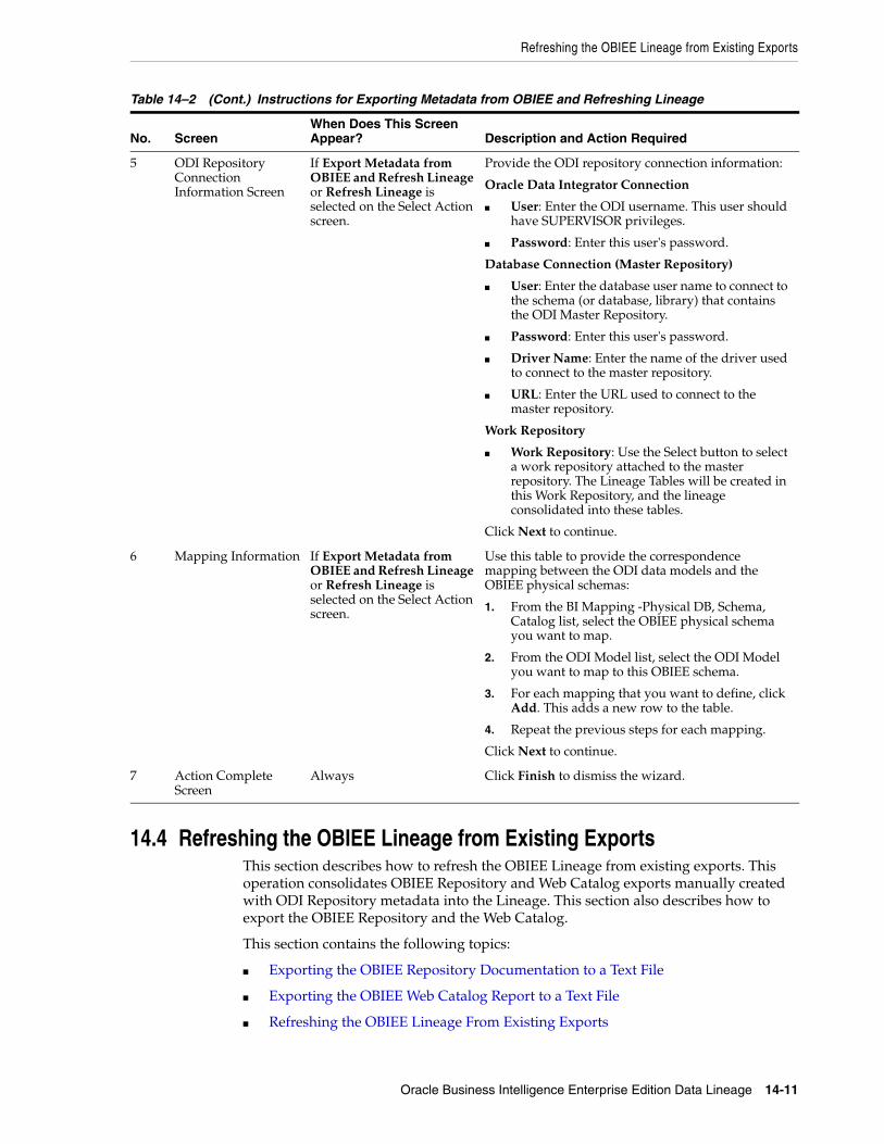
Refreshing the OBIEE Lineage from Existing Exports
Oracle Business Intelligence Enterprise Edition Data Lineage 14-11
14.4 Refreshing the OBIEE Lineage from Existing ExportsThis section describes how to refresh the OBIEE Lineage from existing exports. This operation consolidates OBIEE Repository and Web Catalog exports manually created with ODI Repository metadata into the Lineage. This section also describes how to export the OBIEE Repository and the Web Catalog.
This section contains the following topics:
■ Exporting the OBIEE Repository Documentation to a Text File
■ Exporting the OBIEE Web Catalog Report to a Text File
■ Refreshing the OBIEE Lineage From Existing Exports
5 ODI Repository Connection Information Screen
If Export Metadata from OBIEE and Refresh Lineage or Refresh Lineage is selected on the Select Action screen.
Provide the ODI repository connection information:
Oracle Data Integrator Connection
■ User: Enter the ODI username. This user should have SUPERVISOR privileges.
■ Password: Enter this user's password.
Database Connection (Master Repository)
■ User: Enter the database user name to connect to the schema (or database, library) that contains the ODI Master Repository.
■ Password: Enter this user's password.
■ Driver Name: Enter the name of the driver used to connect to the master repository.
■ URL: Enter the URL used to connect to the master repository.
Work Repository
■ Work Repository: Use the Select button to select a work repository attached to the master repository. The Lineage Tables will be created in this Work Repository, and the lineage consolidated into these tables.
Click Next to continue.
6 Mapping Information If Export Metadata from OBIEE and Refresh Lineage or Refresh Lineage is selected on the Select Action screen.
Use this table to provide the correspondence mapping between the ODI data models and the OBIEE physical schemas:
1. From the BI Mapping -Physical DB, Schema, Catalog list, select the OBIEE physical schema you want to map.
2. From the ODI Model list, select the ODI Model you want to map to this OBIEE schema.
3. For each mapping that you want to define, click Add. This adds a new row to the table.
4. Repeat the previous steps for each mapping.
Click Next to continue.
7 Action Complete Screen
Always Click Finish to dismiss the wizard.
Table 14–2 (Cont.) Instructions for Exporting Metadata from OBIEE and Refreshing Lineage
No. ScreenWhen Does This Screen Appear? Description and Action Required

Refreshing the OBIEE Lineage from Existing Exports
14-12 Oracle Fusion Middleware Connectivity and Knowledge Modules Guide for Oracle Data Integrator
14.4.1 Exporting the OBIEE Repository Documentation to a Text File This section explains how to manually export the OBIEE Repository metadata for consolidating it in the OBIEE Lineage.
To export the OBIEE Repository documentation to a text file:
1. Open the Oracle BI Administration tool and connect to the OBIEE Repository containing the metadata that you want to include in the lineage.
2. In the OBIEE Administration tool, select Tools > Utilities.
3. In the Utilities dialog, select the Repository Documentation utility and click Execute.
4. Save the repository documentation in a temporary file, for example c:\temp\repo_doc.txt.
Make sure to save this repository documentation as Tab-separated values (*.txt) file type
5. Click Save.
14.4.2 Exporting the OBIEE Web Catalog Report to a Text FileThis section explains how to manually export the OBIEE Web Catalog metadata for consolidating it in the OBIEE Lineage.
To export the OBIEE Web Catalog report to a text file:
1. Open OBIEE Catalog Manager and connect to the catalog that contains the metadata that you want to include in the lineage.
2. Select the catalog folder containing the reports that you want to include in the lineage, for example /shared/Paint Demo or /shared/ODI.
3. Select Tools > Create Report.
4. In the Create Catalog Report dialog, select the following columns to include in the report: Owner, Request Folder, Request Name, Request Subject Area, Request Criteria Formula, Request Criteria Table, Request Criteria Column.
Make sure to include these columns in this precise order.
5. Save the report in a temporary file, for example c:\temp\webcat_doc.txt.
6. Click OK.
7. Check the Report Preview and click OK.
14.4.3 Refreshing the OBIEE Lineage From Existing ExportsThis section describes how to refresh the OBIEE Lineage from existing OBIEE Repository and Web Catalog exports created manually.
To refresh the OBIEE Lineage:
1. Start the OBIEE Lineage wizard as described in Section 14.2.3.1, "Installing and Starting the OBIEE Lineage Wizard".
Note: You can also use the refresh lineage script instead of the OBIEE Lineage wizard. See Section 14.5.3, "Automating Lineage Refresh" for more information.

Refreshing the OBIEE Lineage from Existing Exports
Oracle Business Intelligence Enterprise Edition Data Lineage 14-13
The wizard displays a sequence of screens, in the order listed in Table 14–3.
2. Follow the instructions in Table 14–3.
If you need additional help with any of the installation screens, click Help to access the online help.
Table 14–3 Instructions for Refreshing the OBIEE Lineage Artifacts
No. ScreenWhen Does This Screen Appear? Description and Action Required
1 Welcome Screen Always Click Next to continue.
2 Select Action Screen Always Select Refresh Lineage.
Click Next to continue.
3 OBIEE Export Location Screen
Only if Refresh Lineage is selected on the Select Action screen.
Provide the location of the OBIEE metadata exports:
■ Repository Export File: Enter the location of the repository export file. See Section 14.4.1, "Exporting the OBIEE Repository Documentation to a Text File" for more information.
■ Web Catalog Export File: Enter the location of the web catalog export file. See Section 14.4.2, "Exporting the OBIEE Web Catalog Report to a Text File" for more information.
Click Next to continue.

Automating the Lineage Tasks
14-14 Oracle Fusion Middleware Connectivity and Knowledge Modules Guide for Oracle Data Integrator
14.5 Automating the Lineage TasksScripts are also provided to automate the lineage tasks. These scripts can be used instead of the wizard and require that option values are provided in a property file instead.
The scripts for automating the lineage tasks are in the /bin sub-folder of the Lineage installation folder.
This section describes how to automate lineage tasks with scripts and contains the following topics:
■ Configuring the Scripts
■ Automating Lineage Deployment
4 ODI Repository Connection Information Screen
If Export Metadata from OBIEE and Refresh Lineage or Refresh Lineage is selected on the Select Action screen.
Provide the ODI repository connection information:
Oracle Data Integrator Connection
■ User: Enter the ODI username. This user should have SUPERVISOR privileges.
■ Password: Enter this user's password.
Database Connection (Master Repository)
■ User: Enter the database user name to connect to the schema (or database, library) that contains the ODI Master Repository.
■ Password: Enter this user's password.
■ Driver Name: Enter the name of the driver used to connect to the master repository.
■ URL: Enter the URL used to connect to the master repository.
Work Repository
■ Work Repository: Use the Select button to select a work repository attached to the master repository. The Lineage Tables will be created in this Work Repository, and the lineage consolidated into these tables.
Click Next to continue.
5 Mapping Information If Export Metadata from OBIEE and Refresh Lineage or Refresh Lineage is selected on the Select Action screen.
Use this table to provide the correspondence mapping between the ODI data models and the OBIEE physical schemas:
1. From the BI Mapping -Physical DB, Schema, Catalog list, select the OBIEE physical schema you want to map.
2. From the ODI Model list, select the ODI Model you want to map to this OBIEE schema.
3. For each mapping that you want to define, click Add. This adds a new row to the table.
4. Repeat the previous steps for each mapping.
Click Next to continue.
6 Action Complete Screen
Always Click Finish to dismiss the wizard.
Table 14–3 (Cont.) Instructions for Refreshing the OBIEE Lineage Artifacts
No. ScreenWhen Does This Screen Appear? Description and Action Required

Automating the Lineage Tasks
Oracle Business Intelligence Enterprise Edition Data Lineage 14-15
■ Automating Lineage Refresh
14.5.1 Configuring the ScriptsBefore starting any of the scripts, you need to provide the configuration information in a property file. This property file contains the values provided via the wizard user interface.
Figure 14–4 lists the properties defined in the property file.
Note: When running the wizard, a property file is automatically generated in the /tmp sub-folder of the Lineage installation folder. You can re-use this property file as a starting point for working with the command line scripts.
Table 14–4 Properties
Property ValuesRequired for Description
OBIEE_VERSION <10g|11g> install | export |refresh
Version of the OBIEE Server.
OBIEE_RPD <rpd_file_location>
install | export
Location of the repository (.rpd) file of the BI Server.
OBIEE_WEBCAT <web_catalog_folder>
install | export Required only for OBIEE 11g
Location of the Web Catalog folder used by the BI Server.
OBIEE_RPD_PASS <rpd_file_pwd> install | export
The RPD File Password.
OBIEE_RPD_USER <rpd_file_username>
install | export
Required only for OBIEE 10g
The RPD File username.
OBIEE_RPD_EXPORT_FILE
<rpd_export_file_location>
refresh Location of the OBIEE Repository Documentation export file used for refreshing the lineage.
OBIEE_WEBCAT_EXPORT_FILE
<webcat_export_file_location>
refresh Location of the OBIEE Web catalog report used for refreshing the lineage.
OBIEE_ORACLE_HOME
<obiee_oracle_home>
install | export
The BI Server Oracle Home directory
OBIEE_INSTANCE_HOME
<obiee_instance_home>
install | export
Required only for OBIEE 11g.
The BI Server Instance Home directory.
ODI_MASTER_URL
<odi_master_url> export | refresh
The JDBC URL to connect to the ODI Master Repository
ODI_MASTER_DRIVER
<odi_master_driver>
export| refresh
The DB Driver to connect to the ODI Master Repository

Automating the Lineage Tasks
14-16 Oracle Fusion Middleware Connectivity and Knowledge Modules Guide for Oracle Data Integrator
Example 14–1 shows a sample property file:
Example 14–1 Property File
# Version of BIEE Server. Values: 10g / 11gOBIEE_VERSION=10g
# The location of the repository documentation (.rpd) file of the BI ServerOBIEE_RPD=C:/obiee11g/instances/instance2/bifoundation/ OracleBIServerComponent/coreapplication_obis1/repository/TechDemo_11g.rpd
# The location of the Web Catalog folder used by the BI Server. # Required only for OBIEE 11g.OBIEE_WEBCAT=C:/obiee11g/instances/instance2/bifoundation/ OracleBIPresentationServicesComponent/coreapplication_obips1/catalog/TechDemo
# The OBIEE Repository user. Required only for OBIEE 10g. OBIEE_RPD_USER=Administrator# The password of the OBIEE Repository userOBIEE_RPD_PASS=<obiee password>
# The location of the exported Repository Documentation fileOBIEE_RPD_EXPORT_FILE=c:/odi/lineage/run/repo_doc.txt# The location of the exported Web catalog fileOBIEE_WEBCAT_EXPORT_FILE=c:/odi/lineage/run/webcat_doc.txt
# The BI Server Oracle Home directoryOBIEE_ORACLE_HOME=C:/obiee11g/Oracle_BI1 # The BI Server Instance Home directory. Required only for OBIEE 11g.OBIEE_INSTANCE_HOME=C:/obiee11g/instances/instance2
# The JDBC URL to connect to the ODI Master RepositoryODI_MASTER_URL=jdbc:oracle:thin:@localhost:1521:orcl
ODI_SUPERVISOR_PASS
<odi_supervisor_pwd>
export | refresh
The ODI Password for ODI User with SUPERVISOR privileges
ODI_SUPERVISOR_USER
<odi_supervisor_user>
export |refresh
The ODI user with SUPERVISOR privileges
ODI_MASTER_USER
<odi_master_user>
export | refresh
The ODI Master repository username
ODI_MASTER_PASS
<odi_master_password>
export | refresh
The ODI Master repository password
ODI_SECU_WORK_REP
<odi_work_rep> export | refresh
The Name of the Work Repository containing the lineage tables.
OBIEE_WEBCAT_FOLDER_TO_EXPORT
<webcat_folder_to_export>
install | export
The Web Catalog folder to export in the report. For example: /shared/ODI
INSTALL_ODI_LINEAGE
<yes|no> only used in script
Set to yes to deploy ODI Artifacts on the BIEE Server.
EXPORT_OBIEE_METADATA
<yes|no> only used in script
Set to yes to export BI Metadata as flat files. Set to no to only refresh lineage metadata.
Table 14–4 (Cont.) Properties
Property ValuesRequired for Description

Automating the Lineage Tasks
Oracle Business Intelligence Enterprise Edition Data Lineage 14-17
# The JDBC Driver to connect to the ODI Master RepositoryODI_MASTER_DRIVER=oracle.jdbc.OracleDriver# The Database user for the schema that contains the ODI master repository. ODI_MASTER_USER=MASTER_REPO# This user's password ODI_MASTER_PASS=<master_password>
# The ODI user with SUPERVISOR privilegesODI_SUPERVISOR_USER=SUPERVISOR# The ODI Password of the ODI User with SUPERVISOR privilegesODI_SUPERVISOR_PASS=<supervisor password>
# Work Repository containing the lineageODI_SECU_WORK_REP=WORK_REP1
# The Web Catalog folder to export in the report. Eg: /shared/ODIOBIEE_WEBCAT_FOLDER_TO_EXPORT=/shared/ODI
# Option to deploy ODI Artifacts on the BI Server. INSTALL_ODI_LINEAGE=no# Option to export BI Metadata as flat filesEXPORT_OBIEE_METADATA=yes
Encoding PasswordsTo avoid storing the passwords in plain text, use the encode.[sh|bat] <password> command to encode and store the passwords in the property file. If the password are encoded, the property names will change to ODI_MASTER_REPO_ENCODED_PASS, ODI_SUPERVISOR_ENCODED_PASS, and OBIEE_RPD_ENCODED_PASS.
14.5.2 Automating Lineage DeploymentThe install lineage script deploys the following ODI Artifacts in the OBIEE Server:
■ Lineage RPD
■ Lineage Web Catalog (11g OBIEE only)
The script uses the OBIEE tools to merge the Lineage RPD and Lineage Web Catalog with the BIEE Server components.
SyntaxThe script syntax is as follows:
installlineage.bat [-propertyFile=property_file] [-prop_name=prop_value [...]] [-usage]
where:
■ propertyfile represents the Property File that contains all the required properties to install the lineage artifacts. See Section 14.5.1, "Configuring the Scripts" for more information. If no value is specified, the User Wizard will be launched to gather the required information from the User. All the properties in
Note: After running this script, you have to perform the tasks described in Section 14.2.4, "Post-Installation Tasks".

Automating the Lineage Tasks
14-18 Oracle Fusion Middleware Connectivity and Knowledge Modules Guide for Oracle Data Integrator
the property file can be overridden by specifying the property value in the command line option -propName=propValue.
■ prop_name represents the property that can be specified. The value specified in prop_value will override the value specified in the property file (if any).
■ prop_value represents the value for the prop_name property. It will override the value specified in the property file (if any).
■ usage prints the detailed usage information
14.5.3 Automating Lineage RefreshThe refresh lineage script performs one of the following operations, depending on the value set in the EXPORT_OBIEE_METADATA option defined in the property file:
■ Export and refresh metadata, if the EXPORT_OBIEE_METADATA option is set to Yes
■ Refresh lineage metadata, if the EXPORT_OBIEE_METADATA option is set to No
Note that in order to use refreshlineage.sh you need to manually copy the repo_doc.text and the webcat_doc.txt files to the target Linux machine.
SyntaxThe script syntax is as follows:
refreshlineage [-propertyFile=property_file] [-mappingFile=mapping_file] [-prop_name=prop_value [...]] [-usage]
where:
■ propertyfile represents the Property File that contains all the required properties to export and consolidate lineage metadata. See Section 14.5.1, "Configuring the Scripts" for more information. If no value is specified, the User Wizard will be launched to gather the required information from the User. All the properties in the property file can be overridden by specifying the property value in the command line option -prop_name=prop_value.
■ mappingfile represents the mapping of the Model code to BI_PHYSICAL_DB, BI_PHYSICAL_SCHEMA and BI_PHYSICAL_CATALOG. This mapping must be provided in the form of a comma separated values (.csv) file.
Example 14–2 shows a sample mapping file.
Example 14–2 Mapping File
# (c) Copyright Oracle. All rights reserved.# Sample Mapping File for ODI-OBIEE Metadata Lineage# Format: BI Physical DB, BI Physical Schema, BI Physical Catalog, ODI Model ID# Note: Lines starting with # are considered as comments.DB-1,Schema-1,Catalog-1,model1DB-2,Schema-2,Catalog-2,model2
Note: If the propertyFile and mappingFile options are not specified, the UI wizard will be shown to take user input. Otherwise the script will be run from command line itself taking the values from the property file and mapping file to refresh lineage and the UI wizard will not be shown.
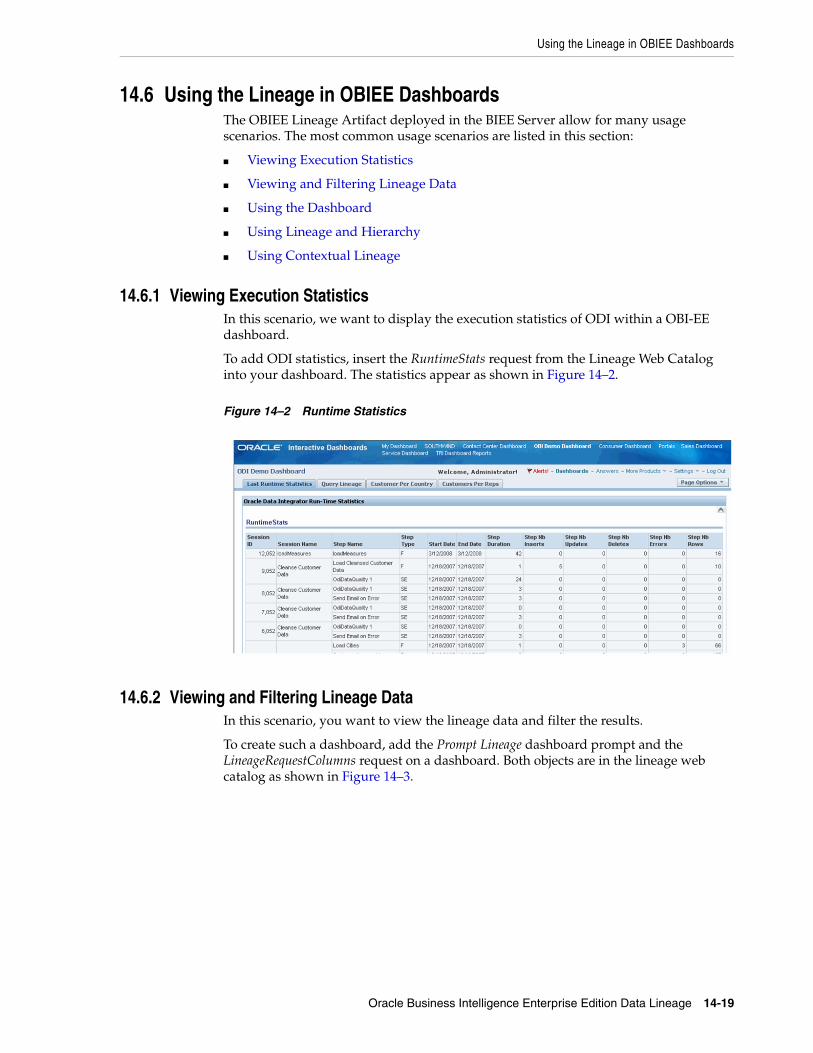
Using the Lineage in OBIEE Dashboards
Oracle Business Intelligence Enterprise Edition Data Lineage 14-19
14.6 Using the Lineage in OBIEE DashboardsThe OBIEE Lineage Artifact deployed in the BIEE Server allow for many usage scenarios. The most common usage scenarios are listed in this section:
■ Viewing Execution Statistics
■ Viewing and Filtering Lineage Data
■ Using the Dashboard
■ Using Lineage and Hierarchy
■ Using Contextual Lineage
14.6.1 Viewing Execution StatisticsIn this scenario, we want to display the execution statistics of ODI within a OBI-EE dashboard.
To add ODI statistics, insert the RuntimeStats request from the Lineage Web Catalog into your dashboard. The statistics appear as shown in Figure 14–2.
Figure 14–2 Runtime Statistics
14.6.2 Viewing and Filtering Lineage DataIn this scenario, you want to view the lineage data and filter the results.
To create such a dashboard, add the Prompt Lineage dashboard prompt and the LineageRequestColumns request on a dashboard. Both objects are in the lineage web catalog as shown in Figure 14–3.

Using the Lineage in OBIEE Dashboards
14-20 Oracle Fusion Middleware Connectivity and Knowledge Modules Guide for Oracle Data Integrator
Figure 14–3 Lineage Web Catalog
Figure 14–4 shows the resulting dashboard.
Figure 14–4 Resulting Dashboard
14.6.3 Using the DashboardIn this dashboard, you can filter using:
■ The Origin of the column (ODI Column or OBI-EE Logical, Physical, Presentation or Request Column)
■ The OBI-EE Folder/Catalog or ODI Project containing the table and the column
■ The Request or table containing the column
Click Go to display the filtered list of columns.
14.6.4 Using Lineage and HierarchyFrom this request, you can display the Lineage and Hierarchy for each column by clicking one of the following buttons:

Using the Lineage in OBIEE Dashboards
Oracle Business Intelligence Enterprise Edition Data Lineage 14-21
Using the LineageThe Lineage icon allows you to drill down into a column lineage. The lineage goes down the following path:
> The OBIEE Presentation Column(s) used in a request's column
> The OBIEE Logical Column(s) used in a Presentation Column
> The OBIEE Physical Column(s) used in a Presentation Column
> The ODI Column(s) corresponding to OBIEE Physical Column(s)
> The ODI source columns used to load a given ODI target column via an ODI mapping. This path can recurse if the source columns are targets for other ODI mappings.
For each level of the lineage, the dashboard displays:
■ The Type, Catalog, Table Name, and Column Name for the (target) column
■ The Type, Catalog, Table Name, and Column Name for the (source) column(s)
■ The transformation Expression between the source column(s) and the target column
■ If the expression is an ODI mapping, you can drill down the ODI run-time statistics (Exec. Stats) for this transformation.
■ You can drill down at any point of the lineage by clicking Lineage in the view.
Figure 14–5 shows one lineage level displayed in a dashboard.
Figure 14–5 Lineage Level
Using the HierarchyThe Hierarchy displays the entire lineage of a given request column in a hierarchical view. Figure 14–6 shows the hierarchical column lineage.
Lineage
Hierarchy
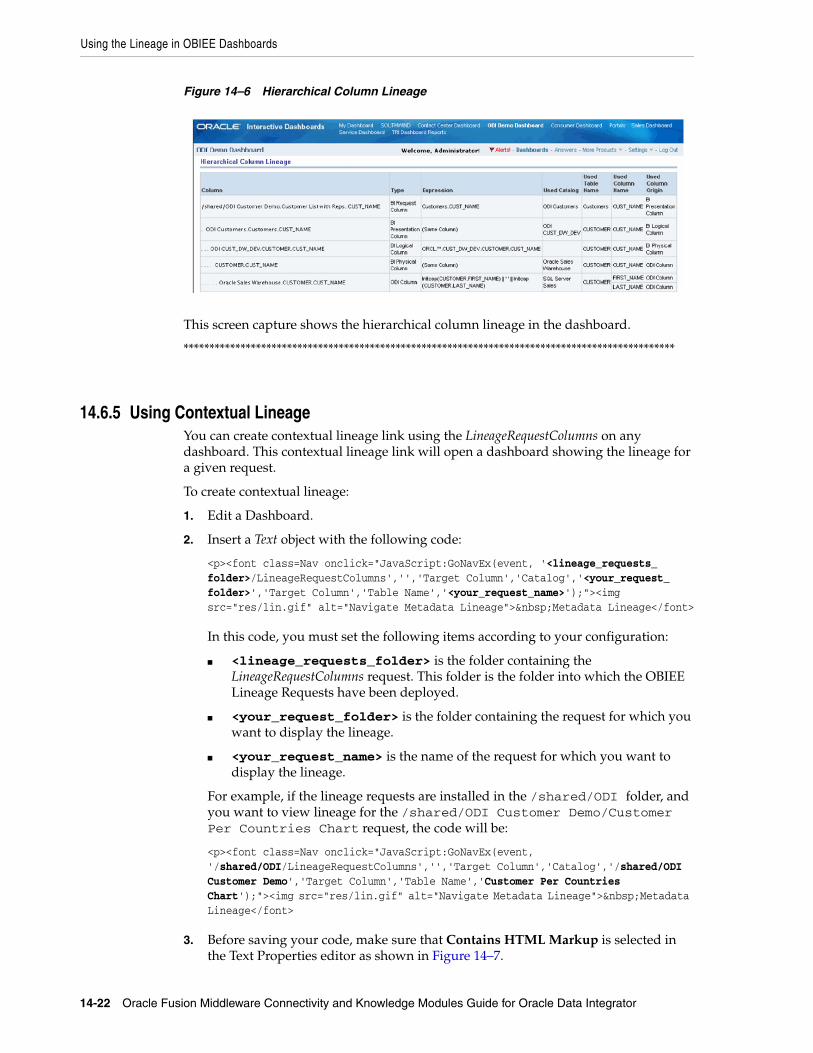
Using the Lineage in OBIEE Dashboards
14-22 Oracle Fusion Middleware Connectivity and Knowledge Modules Guide for Oracle Data Integrator
Figure 14–6 Hierarchical Column Lineage
This screen capture shows the hierarchical column lineage in the dashboard.
***********************************************************************************************
14.6.5 Using Contextual LineageYou can create contextual lineage link using the LineageRequestColumns on any dashboard. This contextual lineage link will open a dashboard showing the lineage for a given request.
To create contextual lineage:
1. Edit a Dashboard.
2. Insert a Text object with the following code:
<p><font class=Nav onclick="JavaScript:GoNavEx(event, '<lineage_requests_folder>/LineageRequestColumns','','Target Column','Catalog','<your_request_folder>','Target Column','Table Name','<your_request_name>');"><img src="res/lin.gif" alt="Navigate Metadata Lineage"> Metadata Lineage</font>
In this code, you must set the following items according to your configuration:
■ <lineage_requests_folder> is the folder containing the LineageRequestColumns request. This folder is the folder into which the OBIEE Lineage Requests have been deployed.
■ <your_request_folder> is the folder containing the request for which you want to display the lineage.
■ <your_request_name> is the name of the request for which you want to display the lineage.
For example, if the lineage requests are installed in the /shared/ODI folder, and you want to view lineage for the /shared/ODI Customer Demo/Customer Per Countries Chart request, the code will be:
<p><font class=Nav onclick="JavaScript:GoNavEx(event, '/shared/ODI/LineageRequestColumns','','Target Column','Catalog','/shared/ODI Customer Demo','Target Column','Table Name','Customer Per Countries Chart');"><img src="res/lin.gif" alt="Navigate Metadata Lineage"> Metadata Lineage</font>
3. Before saving your code, make sure that Contains HTML Markup is selected in the Text Properties editor as shown in Figure 14–7.

Using the Lineage in OBIEE Dashboards
Oracle Business Intelligence Enterprise Edition Data Lineage 14-23
Figure 14–7 Text Properties Editor
This text will create a link on the dashboard that opens the column lineage for the given request.
4. Click OK.
The Metadata Lineage object is added to the dashboard as shown in Figure 14–8.
Figure 14–8 Text Object on Dashboard
Clicking Metadata Lineage displays the dashboard shown in Figure 14–9.
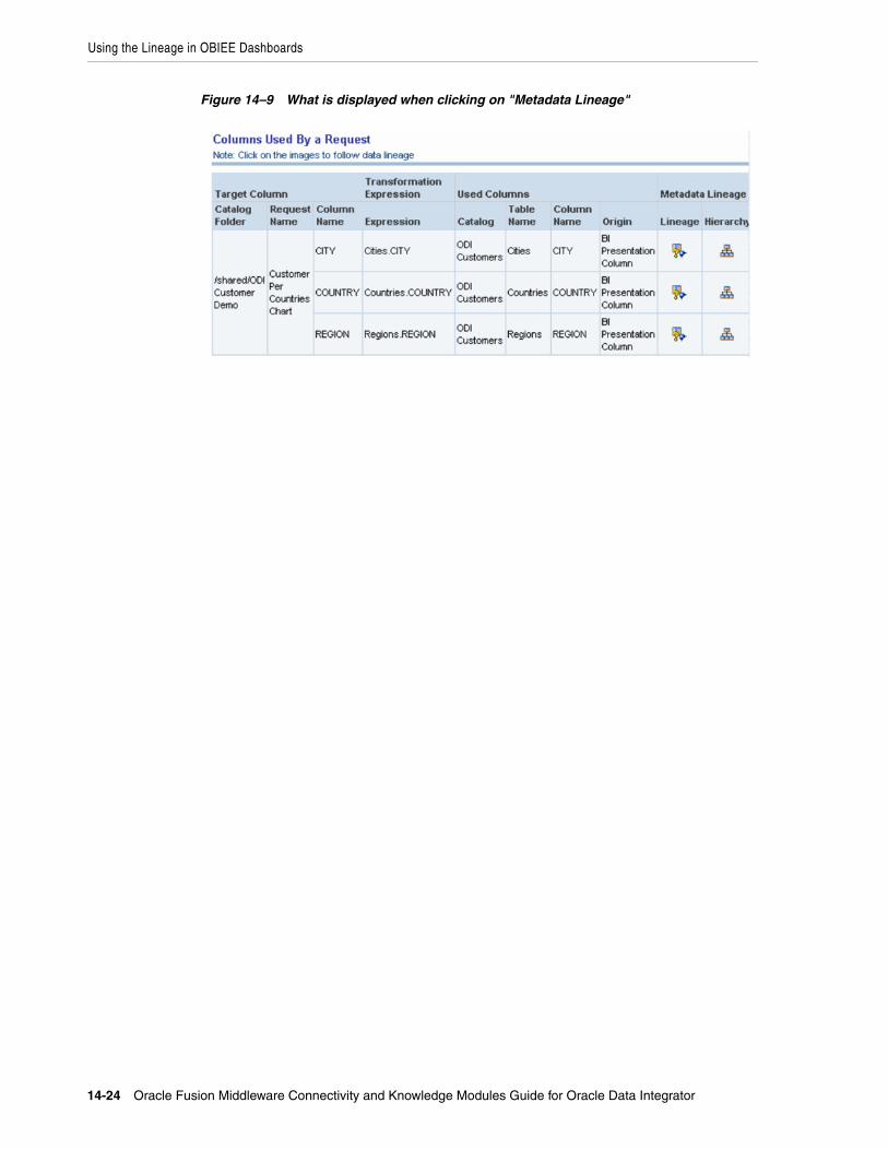
Using the Lineage in OBIEE Dashboards
14-24 Oracle Fusion Middleware Connectivity and Knowledge Modules Guide for Oracle Data Integrator
Figure 14–9 What is displayed when clicking on "Metadata Lineage"

Part IIIPart III Other Technologies
This part describes how to work with other technologies in Oracle Data Integrator.
Part III contains the following chapters:
■ Chapter 15, "JMS"
■ Chapter 16, "JMS XML"
■ Chapter 17, "LDAP Directories"
■ Chapter 18, "Oracle TimesTen In-Memory Database"
■ Chapter 19, "Oracle Changed Data Capture Adapters"
■ Chapter 20, "Oracle GoldenGate"
■ Chapter 21, "Oracle SOA Suite Cross References"


15
JMS 15-1
15JMS
This chapter describes how to work with Java Message Services (JMS) in Oracle Data Integrator.
This chapter includes the following sections:
■ Section 15.1, "Introduction"
■ Section 15.2, "Installation and Configuration"
■ Section 15.3, "Setting up the Topology"
■ Section 15.4, "Setting Up an Integration Project"
■ Section 15.5, "Creating and Defining a JMS Model"
■ Section 15.6, "Designing a Mapping"
■ Section 15.7, "JMS Standard Properties"
15.1 IntroductionOracle Data Integrator provides a simple and transparent method to integrate JMS destinations. This chapter focuses on processing JMS messages with a text payload in batch mode. For XML payload processing, refer to Chapter 16, "JMS XML".
15.1.1 ConceptsThe JMS Knowledge Modules apply to most popular JMS compliant middleware, including Oracle Service Bus, Sonic MQ, IBM Websphere MQ, and so forth. Most of these Knowledge Modules include transaction handling to ensure message delivery.
15.1.1.1 JMS Message StructureThis section describes the structure of a message in a JMS destination.
A JMS Message consists of three sections:
■ Header
■ Properties
■ Payload
HeaderThe header contains in the header fields standard metadata concerning the message, including the destination (JMSDestination), Message ID (JMSMessageID), Message Type (JMSType), and so forth.

Introduction
15-2 Oracle Fusion Middleware Connectivity and Knowledge Modules Guide for Oracle Data Integrator
PropertiesThe properties section contains additional metadata concerning the message. These metadata are properties, that can be separated in three groups:
■ JMS-Defined properties which are optional JMS Headers. Their name begins with JMSX(JMSXUserID, JMSXAppID, etc.).
■ Provider-specific properties. They are specific to the router vendor. Their names start with JMS_<vendor name>.
■ Application-specific properties. These properties depend on the application sending the messages. These are user-defined information that is not included in the message payload.
The Header and Properties sections provide a set of header fields and properties that:
■ Have a specific Java data type (Boolean, string, short, and so forth),
■ Can be accessed for reading and/or writing,
■ Can be used for filtering on the router through the JMS Selector.
PayloadThe payload section contains the message content. This content can be anything (text, XML, binary, and so forth).
15.1.1.2 Using a JMS DestinationOracle Data Integrator is able to process JMS Text and Byte messages that are delivered by a JMS destination. Each message is considered as a container for rows of data and is handled through the JMS Queue or JMS Topic technology.
With JMS Queue/JMS Topic technologies, each JMS destination is defined similarly to a flat file datastore. Each message in the destination is a record in the datastore.
In the topology, each JMS router is defined as a JMS Topic/Queue data server, with a single physical schema. A JMS router may be defined therefore twice to access its topics using one data server, and its queues using another one.
Each JMS destination (Topic of Queue) is defined as a JMS datastore which resource name matches the name of the JMS destination (name of the queue or topic as defined in the router). A model groups message structures related to different topics or queues.
The JMS datastore structure is defined similarly to a flat file (delimited or fixed width). The properties or header fields of the message can be declared with JMS-specific data types as additional pseudo-columns in this flat file structure. Each message in the destination is processed as a record of a JMS datastore.
Processing MessagesJMS destinations are handled as regular file datastores and messages as rows from these datastores. With these technologies, entire message sets are produced and consumed within each mapping.
Message publishing as well consumption requires a commit action to finalize removing/posting the message from/to the JMS destination. Committing is particularly important when reading. Without a commit, the message is read but not consumed. It remains in the JMS Topic/Queue and will be re-read at a later time.
Both the message content and pseudo-columns can be used as regular attributes in the mappings (for mapping, filter, etc.). Certain pseudo-columns (such as the one
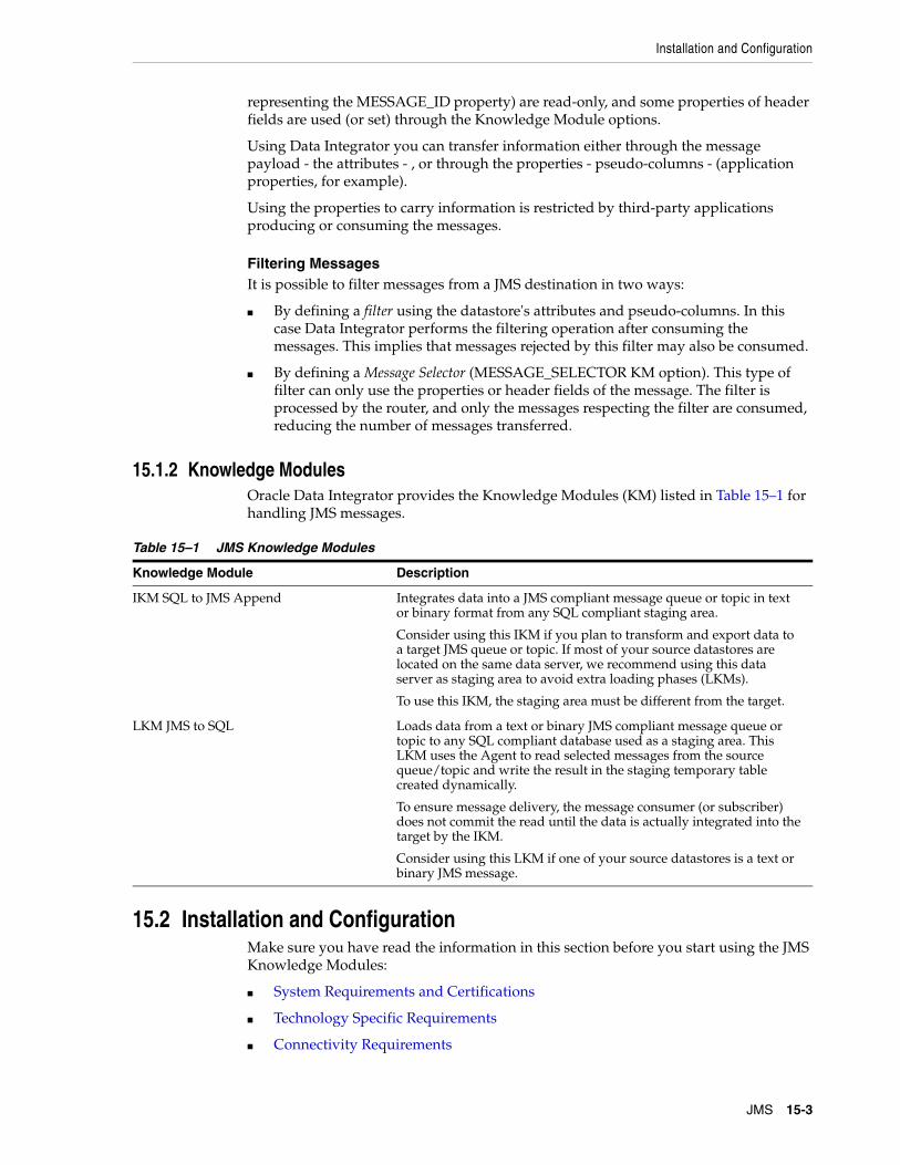
Installation and Configuration
JMS 15-3
representing the MESSAGE_ID property) are read-only, and some properties of header fields are used (or set) through the Knowledge Module options.
Using Data Integrator you can transfer information either through the message payload - the attributes - , or through the properties - pseudo-columns - (application properties, for example).
Using the properties to carry information is restricted by third-party applications producing or consuming the messages.
Filtering MessagesIt is possible to filter messages from a JMS destination in two ways:
■ By defining a filter using the datastore's attributes and pseudo-columns. In this case Data Integrator performs the filtering operation after consuming the messages. This implies that messages rejected by this filter may also be consumed.
■ By defining a Message Selector (MESSAGE_SELECTOR KM option). This type of filter can only use the properties or header fields of the message. The filter is processed by the router, and only the messages respecting the filter are consumed, reducing the number of messages transferred.
15.1.2 Knowledge ModulesOracle Data Integrator provides the Knowledge Modules (KM) listed in Table 15–1 for handling JMS messages.
15.2 Installation and ConfigurationMake sure you have read the information in this section before you start using the JMS Knowledge Modules:
■ System Requirements and Certifications
■ Technology Specific Requirements
■ Connectivity Requirements
Table 15–1 JMS Knowledge Modules
Knowledge Module Description
IKM SQL to JMS Append Integrates data into a JMS compliant message queue or topic in text or binary format from any SQL compliant staging area.
Consider using this IKM if you plan to transform and export data to a target JMS queue or topic. If most of your source datastores are located on the same data server, we recommend using this data server as staging area to avoid extra loading phases (LKMs).
To use this IKM, the staging area must be different from the target.
LKM JMS to SQL Loads data from a text or binary JMS compliant message queue or topic to any SQL compliant database used as a staging area. This LKM uses the Agent to read selected messages from the source queue/topic and write the result in the staging temporary table created dynamically.
To ensure message delivery, the message consumer (or subscriber) does not commit the read until the data is actually integrated into the target by the IKM.
Consider using this LKM if one of your source datastores is a text or binary JMS message.

Setting up the Topology
15-4 Oracle Fusion Middleware Connectivity and Knowledge Modules Guide for Oracle Data Integrator
15.2.1 System Requirements and CertificationsBefore performing any installation you should read the system requirements and certification documentation to ensure that your environment meets the minimum installation requirements for the products you are installing.
The list of supported platforms and versions is available on Oracle Technical Network (OTN):
http://www.oracle.com/technology/products/oracle-data-integrator/index.html.
15.2.2 Technology Specific RequirementsThe JMS destinations are usually accessed via a JNDI service. The configuration and specific requirements for JNDI and JMS depends on the JMS Provider you are connecting to. Refer to the JMS Provider specific documentation for more details.
15.2.3 Connectivity RequirementsOracle Data Integrator does not include specific drivers for JMS providers. Refer to the JMS Provider documentation for the connectivity requirement of this provider.
15.3 Setting up the TopologySetting up the Topology consists of:
1. Creating a JMS Data Server
2. Creating a JMS Physical Schema
15.3.1 Creating a JMS Data ServerA JMS data server corresponds to one JMS provider/router that is accessible through your local network.
It exists two types of JMS data servers: JMS Queue and JMS Topic.
■ A JMS Queue data server is used to access several queues in the JMS router.
■ A JMS Topic data server is used to access several topics in the JMS router
15.3.1.1 Creation of the Data ServerCreate a data server either for the JMS Queue technology or for the JMS Topic technology using the standard procedure, as described in "Creating a Data Server" of the Oracle Fusion Middleware Developer's Guide for Oracle Data Integrator. This section details only the fields required or specific for defining a JMS Queue or JMS Topic data server.
1. In the Definition tab:
■ Name: Name of the data server as it will appear in Oracle Data Integrator.
■ User/Password: Not used here. Leave these fields empty.
2. In the JNDI tab:
■ JNDI Authentication: Set this field to None.
■ JNDI User: Enter the username to connect to the JNDI directory (optional step).

Creating and Defining a JMS Model
JMS 15-5
■ Password: This user's password (optional step).
■ JNDI Protocol: From the list, select the JNDI protocol (optional step).
■ JNDI Driver: Name of the initial context factory java class to connect to the JNDI provider, for example: com.sun.jndi.ldap.LdapCtxFactory for LDAP
■ JNDI URL: <JMS_RESOURCE>, for example ldap://<host>:<port>/<dn> for LDAP
■ JNDI Resource: Logical name of the JNDI resource corresponding to your JMS Queue or Topic connection factory.
For example, specify QueueConnectionFactory if you want to access a message queue and TopicConnectionFactory if you want to access a topic. Note that these parameters are specific to the JNDI directory and the provider.
15.3.2 Creating a JMS Physical SchemaCreate a JMS physical schema using the standard procedure, as described in "Creating a Physical Schema" of the Oracle Fusion Middleware Developer's Guide for Oracle Data Integrator.
Create for this physical schema a logical schema using the standard procedure, as described in "Creating a Logical Schema" of the Oracle Fusion Middleware Developer's Guide for Oracle Data Integrator and associate it in a given context.
15.4 Setting Up an Integration ProjectSetting up a project using JMS follows the standard procedure. See "Creating an Integration Project" of the Oracle Fusion Middleware Developer's Guide for Oracle Data Integrator.
It is recommended to import the following knowledge modules into your project for getting started with JMS:
■ IKM SQL to JMS Append
■ LKM JMS to SQL
15.5 Creating and Defining a JMS ModelThis section contains the following topics:
■ Create a JMS Model
■ Defining the JMS Datastores
15.5.1 Create a JMS ModelCreate a JMS Model using the standard procedure, as described in "Creating a Model" of the Oracle Fusion Middleware Developer's Guide for Oracle Data Integrator.
Note: Only one physical schema is required per JMS data server.
Note: It is not possible to reverse-engineer a JMS model. To create a datastore you have to create a JMS model and define the JMS datastores.

Creating and Defining a JMS Model
15-6 Oracle Fusion Middleware Connectivity and Knowledge Modules Guide for Oracle Data Integrator
A JMS Model is a set of datastores corresponding to the Topics or Queues of a router. Each datastore corresponds to a specific Queue or Topic. The datastore structure defines the message structure for this queue or topic. A model is always based on a Logical Schema. In a given Context, the Logical Schema corresponds to one JMS Physical Schema. The Data Schema corresponding to this Physical Schema contains the Topics or Queues.
15.5.2 Defining the JMS DatastoresIn Oracle Data Integrator, each datastore is a JMS Topic or Queue. Each message in this topic or queue is a row of the datastore.
A JMS message may carry any type of information and there is no metadata retrieval method available. Therefore reverse-engineering is not possible.
To define the datastore structure, do one of the following:
■ Create the datastore as a file datastore and manually declare the message structures.
■ Use the File reverse-engineering through an Excel spreadsheet in order to automate the reverse engineering of messages. See Chapter 3, "Files" for more information about this reverse-engineering method.
■ Duplicate a datastore from another model into the JMS model.
Declaring JMS Properties as Pseudo-ColumnsThe property pseudo-columns represent properties or header fields of a message. These pseudo-columns are defined in the Oracle Data Integrator model as attributes in the JMS datastore, with JMS-specific datatypes. The JMS-specific datatypes are called JMS_xxx (for example: JMS String, JMS Long, JMS Int, and so forth).
To define these property pseudo-columns, simply declare additional attributes named identically to the properties and specified with the appropriate JMS-specific datatypes.
If you define pseudo-columns that are named like standard, provider-specific or application-specific properties, they will be consumed or published with the message as such. If a pseudo-column is not listed in the standard or provider-specific set of JMS properties, It is considered as additional application-specific property.
For example, to use or set in mappings the JMSPriority default property on messages consumed from or pushed to a JMS queue called CUSTOMER, you would add a attribute called JMSPriority (with this exact case) to the CUSTOMER datastore. This attribute would have the JMS Int datatype available for the JMS Queue technology.
Important: The datastores' resource names must be identical to the name of JMS destinations (this is the logical JNDI name) that will carry the message corresponding to their data. Note that these names are frequently case-sensitive.

Designing a Mapping
JMS 15-7
For more information about JMS Properties, see:
■ Section 15.7, "JMS Standard Properties"
■ Section 15.7.1, "Using JMS Properties"
15.6 Designing a MappingYou can use JMS as a source or a target of a mapping. It cannot be used as the staging area.
The KM choice for a mapping or a check determines the abilities and performance of this mapping or check. The recommendations in this section help in the selection of the KM for different situations concerning JMS messages.
15.6.1 Loading Data from a JMS SourceJMS can be used as a source or a target in a mapping. Data from a JMS message Queue or Topic can be loaded to any SQL compliant database used as a staging area. The LKM choice in the Mapping Flow tab to load data between JMS and another type of data server is essential for the performance of a mapping.
Oracle Data Integrator provides the LKM JMS to SQL for loading data from a JMS source to a Staging Area. This LKM loads data from a text or binary JMS compliant message queue or topic to any SQL compliant database used as a staging area.
Table 15–2 lists the JMS specific options.
15.6.2 Integrating Data in a JMS TargetOracle Data Integrator provides the IKM SQL to JMS Append that implements optimized data integration strategies for JMS. This IKM integrates data into a JMS compliant message queue or topic in text or binary format from any SQL compliant staging area. Table 15–2 lists the JMS specific KM options of this IKM.
The IKM choice in the Mapping Flow tab determines the performances and possibilities for integrating.
JMS Knowledge Modules OptionsTable 15–2 lists the JMS specific KM options of the JMS IKM and LKM.
The JMS specific options of this LKM are similar to the options of the IKM SQL to JMS Append. There are only two differences:
■ The DELETE_TEMPORARY_OBJECTS option is only provided for the LKM.
■ The PUBLISH option is only provided for the IKM.
Warning:
■ Property pseudo-columns must be defined and positioned in the JMS datastore after the attributes making up the message payload. Use the Order field in the attribute definition to position these attributes. The order of the pseudo-columns themselves is not important as long as they appear at the end of the datastore definition.
■ Pseudo-columns names are case-sensitive.

Designing a Mapping
15-8 Oracle Fusion Middleware Connectivity and Knowledge Modules Guide for Oracle Data Integrator
Table 15–2 JMS Specific KM Options
Option Used to Description
PUBLISH Write Check this option if you want to publish new messages in the destination. This option is set to Yes by default.
JMS_COMMIT Read/Write Commit the publication or consumption of a message. Uncheck this option if you don't want to commit your publication/consumption on your router. This option is set to Yes by default.
JMSDELIVERYMODE Write JMS delivery mode (1: Non Persistent, 2: Persistent). A persistent message remains on the server and is recovered on server crash.
JMSEXPIRATION Write Expiration delay in milliseconds for the message on the server [0..4 000 000 000]. 0 signifies that the message never expires.
Warning! After this delay, a message is considered as expired, and is no longer available in the topic or queue. When developing mappings it is advised to set this parameter to zero.
JMSPRIORITY Write Relative Priority of the message: 0 (lowest) to 9 (highest).
SENDMESSAGETYPE Write Type of message to send (1 -> BytesMessage, 2 ->TextMessage).
JMSTYPE Write Optional name of the message.
CLIENTID Read Subscriber identification string. This option is described only for JMS compatibility.
Not used for publication.
DURABLE Read D: Session is durable. Indicates that the subscriber definition remains on the router after disconnection.
MESSAGEMAXNUMBER Read Maximum number of messages retrieved [0 .. 4 000 000 000]. 0: All messages are retrieved.
MESSAGETIMEOUT Read Time to wait for the first message in milliseconds [0 .. 4 000 000 000]. if MESSAGETIMEOUT is equal to 0, then there is no timeout.
MESSAGETIMEOUT and MESSAGEMAXNUMBER cannot be both equal to zero. if MESSAGETIMEOUT= 0 and MESSAGEMAXNUMBER =0, then MESSAGETIMEOUT takes the value 1.
Warning! A mapping may retrieve no message if this timeout value is too small.
NEXTMESSAGETIMEOUT Read Time to wait for each subsequent message in milliseconds [0 .. 4 000 000 000]. The default value is 1000.
Warning! A mapping may retrieve only part of the messages available in the topic or the queue if this value is too small.
MESSAGESELECTOR Read Message selector in ISO SQL syntax. See Section 15.7.1, "Using JMS Properties" for more information on message selectors.

JMS Standard Properties
JMS 15-9
15.7 JMS Standard PropertiesThis section describes the JMS properties contained in the message header and how to use them.
In Oracle Data Integrator, pseudo-columns corresponding to the JMS Standard properties should be declared in accordance with the descriptions provided in Table 15–3.
The JMS type and access mode columns refer to the use of these properties in Oracle Data Integrator or in Java programs. In Oracle Data Integrator, some of these properties are used through the IKM options, and the pseudo-column values should not be set by the mappings.
For more details on using these properties in a Java program, see http://java.sun.com/products/jms/.
Table 15–3 Standard JMS Properties of Message Headers
Property JMS TypeAccess (Read/Write) Description
JMSDestination JMS String R Name of the destination (topic or queue) of the message.
JMSDeliveryMode JMS Integer R/W (set by IKM option)
Distribution mode: 1 = Not Persistent or 2 = Persistent. A persistent message is never lost, even if a router crashes.
When sending messages, this property is set by the JMSDELIVERYMODE KM option.
JMSMessageID JMS String R Unique Identifier for a message. This identifier is used internally by the router.
JMSTimestamp JMS Long R Date and time of the message sending operation. This time is stored in a UTC standard format (1).
JMSExpiration JMS Long R/W (set by IKM option)
Message expiration date and time. This time is stored in a UTC standard format (1).
To set this property the JMSEXPIRATION KM option must be used.
JMSRedelivered JMS Boolean R Indicates if the message was resent. This occurs when a message consumer fails to acknowledge the message reception.
JMSPriority JMS Int R/W Name of the destination (topic or queue) the message replies should be sent to.
JMSCorrelationID JMS String R/W Correlation ID for the message. This may be the JMSMessageID of the message this message generating this reply. It may also be an application-specific identifier.

JMS Standard Properties
15-10 Oracle Fusion Middleware Connectivity and Knowledge Modules Guide for Oracle Data Integrator
Table 15–4 lists the optional JMS-defined properties in the JMS standard.
(1): The UTC (Universal Time Coordinated) standard is the number of milliseconds that have elapsed since January 1st, 1970
15.7.1 Using JMS PropertiesIn addition to their contents, messages have a set of properties attached to them. These may be provider-specific, application-specific (user defined) or JMS Standard Properties.
JMS properties are used in Oracle Data Integrator as complementary information to the message, and are used, for example, to filter the messages.
JMSType JMS String R/W (set by IKM option)
Message type label. This type is a string value describing the message in a functional manner (for example SalesEvent, SupportProblem).
To set this property the JMSTYPE KM option must be used.
Table 15–4 Optional JMS Properties of Message Headers
Property JMS TypeAccess (Read/Write) Description
JMSXUserID JMS String R Client User ID.
JMSXAppID JMS String R Client Application ID.
JMSSXProducerTXID
JMS String R Transaction ID for the production session. This ID is the same for all the messages sent to a destination by a producer between two JMS commit operations.
JMSSXConsumerTXID
JMS String R Transaction ID for current consumption session. This ID is the same of a batch of message read from a destination by a consumer between two JMS commit read operations.
JMSXRcvTimestamp
JMS Long R Message reception date and time. This time is stored in a UTC standard format (1).
JMSXDeliveryCount
JMS Int R Number of times a message is received. Always set to 1.
JMSXState JMS Int R Message state. Always set to 2 (Ready).
JMSXGroupID JMS String R/W ID of the group to which the message belongs.
JMSXGroupSeq JMS Int R/W Sequence number of the message in the group of messages.
Table 15–3 (Cont.) Standard JMS Properties of Message Headers
Property JMS TypeAccess (Read/Write) Description

JMS Standard Properties
JMS 15-11
15.7.1.1 Declaring JMS PropertiesWhen Defining the JMS Datastores, you must append pseudo-columns corresponding to the JMS properties that you want to use in your mappings. See Declaring JMS Properties as Pseudo-Columns for more information.
15.7.1.2 Filtering on the RouterWith this type of filtering, the filter is specified when sending the JMS read query. Only messages matching the message selector filter are retrieved. The message selector is specified in Oracle Data Integrator using the MESSAGE_SELECTOR KM option
The MESSAGE_SELECTOR is programmed in an SQL WHERE syntax. Comparison, boolean and mathematical operators are supported:
+, -, *, /, =, >, <, <>, >=, <=, OR, AND, BETWEEN, IN, NOT, LIKE, IS NULL.
ExamplesFilter all messages with priority greater than 5
JMSPriority > 5
Filter all messages with priority not less than 6 and with the type Sales_Event.
NOT JMSPriority < 6 AND JMSType = 'Sales_Event'
15.7.1.3 Filtering on the ClientFiltering is performed after receiving the messages, and is setup by creating a standard Oracle Data Integrator mapping filter, which must be executed on the staging area. A filter uses pseudo-columns from the source JMS datastore. The pseudo-columns defined in the Oracle Data Integrator datastore represent the JMS properties. See Declaring JMS Properties as Pseudo-Columns for more information. Note that messages filtered this way are considered as consumed from the queue or topic.
15.7.1.4 Using Property Values as Source DataIt is possible to use the values of JMS properties as source data in a mapping. This is carried out by specifying the pseudo-columns of the source JMS datastore in the mapping. See Declaring JMS Properties as Pseudo-Columns for more information.
Note: Router filtering is not a JMS mandatory feature. It may be unavailable. Please confirm that it is available by reviewing the JMS provider documentation.
Notes:
■ The IS NULL clause handles properties with an empty value but does not handle nonexistent application-specific properties.
For example, if the selector COLOR IS NULL is defined, a message with the application-specific property COLOR specified with an empty value is consumed correctly. Another message in the same topic/queue without this property specified would raise an exception.

JMS Standard Properties
15-12 Oracle Fusion Middleware Connectivity and Knowledge Modules Guide for Oracle Data Integrator
15.7.1.5 Setting Properties when Sending a MessageWhen sending messages it is possible to specify JMS properties by mapping values of the pseudo-columns in a mapping targeting a JMS datastore. Certain properties may be set using KM options. See Section 15.7, "JMS Standard Properties" for more information.

16
JMS XML 16-1
16JMS XML
This chapter describes how to work with Java Message Services (JMS) with a XML payload in Oracle Data Integrator.
This chapter includes the following sections:
■ Section 16.1, "Introduction"
■ Section 16.2, "Installation and Configuration"
■ Section 16.3, "Setting up the Topology"
■ Section 16.4, "Setting Up an Integration Project"
■ Section 16.5, "Creating and Reverse-Engineering a JMS XML Model"
■ Section 16.6, "Designing a Mapping"
16.1 IntroductionOracle Data Integrator provides a simple and transparent method to integrate JMS destinations. This chapter focuses on processing JMS messages with a XML payload. For text payload processing in batch mode, refer to Chapter 15, "JMS".
16.1.1 ConceptsThe JMS XML Knowledge Modules apply to most popular JMS compliant middleware, including Oracle Service Bus, Sonic MQ, IBM Websphere MQ, and so forth. Most of these Knowledge Modules include transaction handling to ensure message delivery.
16.1.1.1 JMS Message StructureSee Section 16.1.1.1, "JMS Message Structure" for information about the JMS message structure.
16.1.1.2 Using a JMS DestinationOracle Data Integrator is able to process XML messages that are delivered by a JMS destination. Each message is considered as a container for XML data and is handled through the JMS XML Queue or JMS XML Topic technology.
With JMS XML Queue/JMS XML Topic technologies, each messages payload contains a complete XML data structure. This structure is mapped into a relational schema (XML Schema) that appears as a model, using the Oracle Data Integrator XML Driver.

Introduction
16-2 Oracle Fusion Middleware Connectivity and Knowledge Modules Guide for Oracle Data Integrator
In the topology, each JMS destination is defined as a JMS XML Topic/Queue data server with a single physical schema. A data server/physical schema pair will be declared for each topic or queue delivering message in the XML format.
The structure of the XML message mapped into a relational structure (called the XML schema) appears as a data model. Each datastore in this model represents a portion (typically, an element type) in the XML file.
Processing MessagesAs each XML message corresponds to an Oracle Data Integrator model, the entire model must be used and loaded as one single unit when a JMS XML message is consumed or produced. The processing unit for an XML message is the package.
It is not possible to declare the properties or header fields of the message in the model or use them as attributes in a mapping. They still can be used in message selectors, or be set through KM options.
Consuming an XML messageProcessing an incoming XML message is performed in packages as follows:
1. Synchronize the JMS message to the XML schema: This operation reads the message and generates the XML schema. This is usually performed by the first mapping accessing the message.
2. Extract the data: A sequence of mappings use datastores from the XML schema as sources. This data is usable until the session is terminated, another message is read by a new Synchronize action, or the Commit JMS Read is performed.
3. Commit JMS Read: This operation validates the message consumption and deletes the XML schema. It should be performed by the last mapping which extracts data from the XML message.
Producing an XML messageTo produce an XML message, a package must be designed to perform the following tasks:
1. Initialize the XML schema: This operation creates an empty XML schema corresponding to the XML message to generate. This operation is usually performed in the first mapping loading the structure.
2. Load the data: A sequence of mappings loads data into the XML schema.
3. Synchronize the XML schema to JMS: This operation converts the XML schema to an XML message, and sends it to the JMS destination. This operation is usually performed by the last mapping loading the schema.
Filtering MessagesIt is possible to filter messages from a JMS XML destination by defining a Message Selector (MESSAGE_SELECTOR KM option) to filter messages on the server. This type of filter can use only the properties or header fields of the message. The filter is
Note: This method is extremely similar to XML files processing. In JMS XML, the message payload is the XML file. See Chapter 5, "XML Files"and Appendix B, "Oracle Data Integrator Driver for XML Reference"for more information about XML Files processing and the XML Driver.

Installation and Configuration
JMS XML 16-3
processed by the server, reducing the amount of information read by Data Integrator. It is also possible to filter data in the mapping using data extracted from the XML schema. These filters are processed in Data Integrator, after the message is synchronized to the XML schema.
16.1.2 Knowledge ModulesOracle Data Integrator provides the Knowledge Modules (KM) listed in Table 16–1 for handling XML messages.
16.2 Installation and ConfigurationMake sure you have read the information in this section before you start using the JMS Knowledge Modules:
■ System Requirements and Certifications
■ Technology Specific Requirements
■ Connectivity Requirements
16.2.1 System Requirements and CertificationsBefore performing any installation you should read the system requirements and certification documentation to ensure that your environment meets the minimum installation requirements for the products you are installing.
The list of supported platforms and versions is available on Oracle Technical Network (OTN):
http://www.oracle.com/technology/products/oracle-data-integrator/index.html.
16.2.2 Technology Specific RequirementsThe JMS destinations are usually accessed via a JNDI service. The configuration and specific requirements for JNDI and JMS depends on the JMS Provider you are connecting to. Refer to the JMS Provider specific documentation for more details.
16.2.3 Connectivity RequirementsThis section lists the requirements for connecting to a JMS XML database.
Oracle Data Integrator does not include specific drivers for JMS providers. Refer to the JMS Provider documentation for the connectivity requirement of this provider.
XML ConfigurationXML content is accessed through the Oracle Data Integrator JDBC for XML driver. The driver is installed with Oracle Data Integrator.
Table 16–1 JMS XML Knowledge Modules
Knowledge Module Description
IKM SQL to JMS XML Append Integrates data into a JMS compliant message queue or topic in XML format from any ANSI SQL-92 standard compliant staging area.
LKM JMS XML to SQL Loads data from a JMS compliant message queue or topic in XML to any ANSI SQL-92 standard compliant database used as a staging area.

Setting up the Topology
16-4 Oracle Fusion Middleware Connectivity and Knowledge Modules Guide for Oracle Data Integrator
Ask your system administrator for the location of the DTD file describing the XML content.
16.3 Setting up the TopologySetting up the Topology consists of:
1. Creating a JMS XML Data Server
2. Creating a JMS XML Physical Schema
16.3.1 Creating a JMS XML Data ServerAn JMS XML data server corresponds to one JMS provider/router that is accessible through your local network.
There are two types of JMS XML data servers: JMS Queue XML and JMS Topic XML.
■ A JMS Queue XML data server is used to connect a single queue in the JMS router to integrate XML messages.
■ A JMS Topic XML data server is used to connect a single Topic in the JMS router to integrate XML messages.
The Oracle Data Integrator JMS driver loads the messages that contains the XML content into a relational schema in memory. This schema represents the hierarchical structure of the XML message and enables unloading the relational structure back to the JMS messages.
16.3.1.1 Creation of the Data ServerCreate a data server either for the JMS Queue XML technology or for the JMS Topic XML technology using the standard procedure, as described in "Creating a Data Server" of the Oracle Fusion Middleware Developer's Guide for Oracle Data Integrator.
The creation process for a JMS XML Queue or JMS Topic XML data server is identical to the creation process of an XML data server except that you need to define a JNDI connection with JMS XML specific information in the JNDI URL. See Section 5.3.1, "Creating an XML Data Server" for more information.
This section details only the fields required or specific for defining a JMS Queue XML or JMS Topic XML data server.
1. In the Definition tab:
■ Name: Name of the data server as it will appear in Oracle Data Integrator.
■ User/Password: Not used here. Leave these fields empty.
2. In the JNDI tab:
■ JNDI Authentication: From the list, select the authentication mode.
■ JNDI User: Enter the username to connect to the JNDI directory (not mandatory).
■ Password: This user's password (not mandatory).
■ JNDI Protocol: From the list, select the JNDI protocol (not mandatory).
■ JNDI Driver: Name of the initial context factory java class to connect to the JNDI provider, for example:
com.sun.jndi.ldap.LdapCtxFactory

Setting up the Topology
JMS XML 16-5
■ JNDI URL: <JMS_RESOURCE>?d=<DTD_FILE>&s=<SCHEMA>&JMS_DESTINATION=<JMS_DESTINATION_NAME>.
The JNDI URL properties are described inTable 16–2.
■ JNDI Resource: Logical name of the JNDI resource corresponding to your JMS Queue (or Topic) connection factory.
ExampleIf using an LDAP directory as the JNDI provider, you should use the following parameters:
■ JNDI Driver: com.sun.jndi.ldap.LdapCtxFactory
■ JNDI URL: ldap://<ldap_host>:<port>/<dn>?d=<DTD_FILE>&s=<SCHEMA>&JMS_DESTINATION=<JMS_DESTINATION_NAME>
■ JNDI Resource: <Name of the connection factory>
Note: Specify QueueConnectionFactory if you want to access a message queue and TopicConnectionFactory if you want to access a topic. Note that these parameters are specific to the JNDI directory.
Table 16–2 JNDI URL Properties
Parameter Value Notes
d <DTD File location> DTD File location (relative or absolute) in UNC format. Use slash "/" in the path name and not backslash "\" in the file path. This parameter is mandatory.
re <Root element> Name of the element to take as the root table of the schema. This value is case sensitive. This parameter can be used for reverse-engineering a specific message definition from a WSDL file, or when several possible root elements exist in a XSD file.
ro true | false If true, the XML file is opened in read only mode.
s <schema name> Name of the relational schema where the XML file will be loaded.This value must match the one set for the physical schema attached to this data server. This parameter is mandatory.
cs true | false Load the XML file in case sensitive or insensitive mode. For case insensitive mode, all element names in the DTD file should be distinct (Ex: Abc and abc in the same file are banned). The case sensitive parameter is a permanent parameter for the schema. It CANNOT be changed after schema creation. Please note that when opening the XML file in insensitive mode, case will be preserved for the XML file.
JMSXML_ROWSEPARATOR
5B23245D Hexadecimal code of the string used as a line separator (line break) for different XML contents. Default value is 5B23245D which corresponds to the string [#$].
JMS_DESTINATION
JNDI Queue name or Topic name
JNDI Name of the JMS Queue or Topic. This parameter is mandatory.
tna boolean (true|false) Transform Non Ascii. Set to false to keep non-ascii characters. Default is true. This parameter is not mandatory.

Setting Up an Integration Project
16-6 Oracle Fusion Middleware Connectivity and Knowledge Modules Guide for Oracle Data Integrator
16.3.2 Creating a JMS XML Physical SchemaCreate a JMS XML physical schema using the standard procedure, as described in "Creating a Physical Schema" of the Oracle Fusion Middleware Developer's Guide for Oracle Data Integrator.
Create for this physical schema a logical schema using the standard procedure, as described in "Creating a Logical Schema" of the Oracle Fusion Middleware Developer's Guide for Oracle Data Integrator and associate it in a given context.
16.4 Setting Up an Integration ProjectSetting up a project using JMS XML follows the standard procedure. See "Creating an Integration Project" of the Oracle Fusion Middleware Developer's Guide for Oracle Data Integrator.
It is recommended to import the following knowledge modules into your project for getting started with JMS XML:
■ IKM SQL to JMS XML Append
■ LKM JMS XML to SQL
16.5 Creating and Reverse-Engineering a JMS XML ModelThis section contains the following topics:
■ Create a JMS XML Model
■ Reverse-Engineering a JMS XML Model
16.5.1 Create a JMS XML ModelCreate a JMS Queue XML or JMS Topic XML Model using the standard procedure, as described in "Creating a Model" of the Oracle Fusion Middleware Developer's Guide for Oracle Data Integrator.
A JMS Queue XML or JMS Topic XML Model corresponds to a set of datastores, with each datastore representing an entry level in the XML file. The models contain datastores describing the structure of the JMS messages. A model contains the message structure of one topic or one queue. This model's structure is reverse-engineered from the DTD or the XML file specified in the data server definition, using standard reverse-engineering.
16.5.2 Reverse-Engineering a JMS XML ModelJMS XML supports Standard reverse-engineering - which uses only the abilities of the XML driver.
Note: For the name of the Schema and Work Schema use the schema name defined in the s=<schema name> property of the JNDI URL of the JMS Queue XML or JMS Topic XML data server.
Note: Only one physical schema is required per JMS XML data server.

Designing a Mapping
JMS XML 16-7
To perform a Standard Reverse-Engineering on JMS Queue XML or JMS Topic XML use the usual procedure, as described in "Reverse-engineering a Model" of the Oracle Fusion Middleware Developer's Guide for Oracle Data Integrator.
Oracle Data Integrator will automatically add the following attributes to the datastores generated from the XML data:
■ Primary keys (PK attributes) for parent-child relationships
■ Foreign keys (FK attributes) for parent-child relationships
■ Order identifier (ORDER attributes) to enable the retrieval of the order in which the data appear in the XML file.
These extra attributes enable the hierarchical XML structure's mapping in a relational structure stored in the schema. See Appendix B, "Oracle Data Integrator Driver for XML Reference" for more information.
16.6 Designing a MappingThe KM choice for a mapping or a check determines the abilities and performance of this mapping or check. The recommendations in this section help in the selection of the KM for different situations concerning XML messages.
16.6.1 Loading Data from a JMS XML SourceJMS XML can be used as a source or a target in a mapping. Data from an XML message Queue or Topic can be loaded to any ANSI SQL-92 standard compliant database used as a staging area. The LKM choice in the Mapping Flow tab to load data between JMS XML and another type of data server is essential for successful data extraction.
Oracle Data Integrator provides the LKM JMS XML to SQL for loading data from a JMS compliant message queue or topic in XML to any ANSI SQL-92 standard compliant database used as a staging area. This LKM uses the Agent to read selected messages from the source queue/topic and write the result in the staging temporary table created dynamically.To ensure message delivery, the message consumer (or subscriber) does not commit the read until the data is actually integrated into the target by the IKM.Consider using this LKM if one of your source datastores is an XML JMS message.
In order to load XML messages from a JMS provider, the following steps must be followed:
■ The first mapping reading the XML message from the JMS XML source must use the LKM JMS XML to SQL with the SYNCHRO_JMS_TO_XML LKM option set to Yes. This option creates and loads the XML schema from the message retrieved from the queue or topic.
■ The last mapping should commit the message consumption by setting the JMS_COMMIT to Yes.
Table 16–3 lists the JMS specific options of this knowledge module.
16.6.2 Integrating Data in a JMS XML TargetOracle Data Integrator provides the IKM SQL to JMS XML Append that implements optimized data integration strategies for JMS XML. This IKM integrates data into a JMS compliant message queue or topic in XML format from any ANSI SQL-92 standard compliant staging area.

Designing a Mapping
16-8 Oracle Fusion Middleware Connectivity and Knowledge Modules Guide for Oracle Data Integrator
To use this IKM, the staging area must be different from the target.
In order to integrate XML data into a JMS XML target, the following steps must be followed:
■ The first mapping loading the XML schema must provide a value for the ROOT_TABLE (it is the model's table that corresponds to the root element of the XML file), and also set the INITIALIZE_XML_SCHEMA option to Yes.
■ The mappings should load the datastores in the hierarchy order, starting by the top of the hierarchy and going down. The mappings loading subsequent levels of the XML schema hierarchy should load the foreign key attribute linking the current hierarchy level to a higher one.
For example, when loading the second level of the hierarchy (the one under the root table), the foreign key attribute should be set to '0' (Zero), as it is the value that is set by the IKM in the root table primary key when the root table is initialized.
■ The last mapping should send the XML schema to the JMS provider by setting the SYNCHRO_JMS_TO_XML parameter to Yes.
ExampleAn XML file format generates a schema with the following hierarchy of datastores:
+ GEOGRAPHY_DIM (GEO_DIMPK, ...) | +--- COUNTRY (GEO_DIMFK, COUNTRYPK, COUNTRY_NAME, ...) | +--- REGION (COUNTRYFK, REGIONPK, REGION_NAME, ...)
In this hierarchy, GEOGRAPHY_DIM is the root table, and its GEOGRAPHY_DIMPK attribute is set to '0' at initialization time. The tables should be loaded in the GEOGRAPHY_DIM, COUNTRY, REGION sequence.
■ When loading the second level of the XML hierarchy (COUNTRY) make sure that the FK field linking this level to the root table level is set to '0'. In the model above, when loading COUNTRY, we must load the COUNTRY.GEOGRAPHY_DIMFK set to '0'.
■ You must also link the records of REGION to the COUNTRY level by loading the REGION.COUNTRYFK attribute with values that correspond to a parent record in COUNTRY (having REGION.COUNTRYFK = COUNTRY.COUNTRYPK).
For more information on loading data to XML schemas, see Appendix B, "Oracle Data Integrator Driver for XML Reference".
Table 16–3 lists the JMS specific KM options of this IKM. Options that are specific to XML messages are in bold.
JMS XML Knowledge Modules OptionsTable 16–3 lists the KM options for the LKM and IKM for JMS XML. Options that are specific to XML messages are in bold.
Note: The root table of the XML schema usually corresponds to the datastore at the top of the hierarchy tree view of the JMS XML model. Therefore the ROOT_TABLE parameter should take the value of the resource name for this datastore.

Designing a Mapping
JMS XML 16-9
Although most options are the same for the LKM and IKM, there are only few differences:
■ The INITIALIZE_XML_SCHEMA and ROOT_TABLE options are only provided for the IKM.
■ The DELETE_TEMPORARY_OBJECTS and JMS_COMMIT options are only provided for the LKM.
■ Set JMS_COMMIT to Yes to commit the message consumption on the Router (JMS XML).
Table 16–3 JMS Specific KM Options
Option Used to Description
CLIENTID Read Subscriber identification string.
Not used for publication.
DURABLE Read D: Session is durable. Indicates that the subscriber definition remains on the router after disconnection.
INITIALIZE_XML_SCHEMA
Write Initializes an empty XML schema. This option must be set to YES for the first mapping loading the schema.
JMSDELIVERYMODE Write JMS delivery mode (1: Non Persistent, 2: Persistent). A persistent message remains on the server and is recovered on server crash.
JMSEXPIRATION Write Expiration delay in milliseconds for the message on the server [0..4 000 000 000]. 0 signifies that the message never expires.
Warning! After this delay, a message is considered as expired, and is no longer available in the topic or queue. When developing mappings it is advised to set this parameter to zero.
JMSPRIORITY Write Relative Priority of the message: 0 (lowest) to 9 (highest).
JMSTYPE Write Optional name of the message.
MESSAGEMAXNUMBER Read Maximum number of messages retrieved [0 .. 4 000 000 000]. 0: All messages are retrieved.
MESSAGESELECTOR Read Message selector in ISO SQL syntax for filtering on the router. See Section 15.7.1, "Using JMS Properties" for more information on message selectors.
MESSAGETIMEOUT Read Time to wait for the first message in milliseconds [0 .. 4 000 000 000]. If MESSAGETIMEOUT is equal to 0, then there is no timeout.
MESSAGETIMEOUT and MESSAGEMAXNUMBER cannot be both equal to zero. If MESSAGETIMEOUT= 0 and MESSAGEMAXNUMBER =0, then MESSAGETIMEOUT takes the value 1.
Warning! A mapping may retrieve no message if this timeout value is too small.

Designing a Mapping
16-10 Oracle Fusion Middleware Connectivity and Knowledge Modules Guide for Oracle Data Integrator
NEXTMESSAGETIMEOUT Read Time to wait for each subsequent message in milliseconds [0 .. 4 000 000 000]. The default value is 1000.
Warning! A mapping may retrieve only part of the messages available in the topic or the queue if this value is too small.
ROOT_TABLE Write Resource name of the datastore that is the root of the XML model hierarchy.
SENDMESSAGETYPE Write Type of message to send (1 -> BytesMessage, 2 ->TextMessage).
SYNCHRO_XML_TO_JMS Write Generates the XML message from the XML schema, and sends this message. This option must be set to YES for the last mapping that writes to the schema XML.
Table 16–3 (Cont.) JMS Specific KM Options
Option Used to Description
17
LDAP Directories 17-1
17LDAP Directories
This chapter describes how to work with LDAP directories in Oracle Data Integrator.
This chapter includes the following sections:
■ Section 17.1, "Introduction"
■ Section 17.2, "Installation and Configuration"
■ Section 17.3, "Setting up the Topology"
■ Section 17.4, "Setting Up an Integration Project"
■ Section 17.5, "Creating and Reverse-Engineering an LDAP Directory"
■ Section 17.6, "Designing a Mapping"
■ Section 17.7, "Troubleshooting"
17.1 IntroductionOracle Data Integrator supports LDAP directories integration using the Oracle Data Integrator Driver for LDAP.
17.1.1 ConceptsThe LDAP concepts map the Oracle Data Integrator concepts as follows: An LDAP directory tree, more specifically the entry point to this LDAP tree, corresponds to a data server in Oracle Data Integrator. Within this data server, a single schema maps the content of the LDAP directory tree.
The Oracle Data Integrator Driver for LDAP (LDAP driver) loads the hierarchical structure of the LDAP tree into a relational schema. This relational schema is a set of tables that can be queried or modified using standard SQL statements.
The relational schema is reverse-engineered as a data model in ODI, with tables, columns, and constraints. This model is used like a normal relational data model in ODI. Any changes performed in the relational schema data (insert/update) is immediately impacted by the driver in the LDAP data.
See Appendix A, "Oracle Data Integrator Driver for LDAP Reference" for more information on this driver.
17.1.2 Knowledge ModulesOracle Data Integrator does not provide specific Knowledge Modules (KM) for the LDAP technology. You can use LDAP as a SQL data server. LDAP data servers support both the technology-specific KMs sourcing or targeting SQL data servers, as well as

Installation and Configuration
17-2 Oracle Fusion Middleware Connectivity and Knowledge Modules Guide for Oracle Data Integrator
the generic KMs. See Chapter 4, "Generic SQL" or the technology chapters for more information on these KMs.
17.2 Installation and ConfigurationMake sure you have read the information in this section before you start working with the LDAP technology.
■ System Requirements
■ Technologic Specific Requirements
■ Connectivity Requirements
17.2.1 System RequirementsBefore performing any installation you should read the system requirements and certification documentation to ensure that your environment meets the minimum installation requirements for the products you are installing.
The list of supported platforms and versions is available on Oracle Technical Network (OTN):
http://www.oracle.com/technology/products/oracle-data-integrator/index.html.
17.2.2 Technologic Specific RequirementsThere are no technology-specific requirements for using LDAP directories in Oracle Data Integrator.
17.2.3 Connectivity RequirementsThis section lists the requirements for connecting to LDAP database.
Oracle Data Integrator Driver for LDAPLDAP directories are accessed through the Oracle Data Integrator Driver for LDAP. This JDBC driver is installed with Oracle Data Integrator.
To connect to an LDAP directory you must ask the system administrator for the following connection information:
■ The URL to connect to the directory
■ The User and Password to connect to the directory
■ The Base Distinguished Name (Base DN). This is the location in the LDAP tree that ODI will access.
You may also require a connection to the Reference LDAP Tree structure and to an External Storage database for the driver. See Appendix B, "Oracle Data Integrator Driver for XML Reference" for more information on these concepts and configuration parameters.
17.3 Setting up the TopologySetting up the topology consists in:
1. Creating an LDAP Data Server

Setting up the Topology
LDAP Directories 17-3
2. Creating a Physical Schema for LDAP
17.3.1 Creating an LDAP Data ServerAn LDAP data server corresponds to an LDAP tree that is accessible to Oracle Data Integrator.
17.3.1.1 Creation of the Data ServerCreate a data server for the LDAP technology using the standard procedure, as described in "Creating a Data Server" of the Developer's Guide for Oracle Data Integrator. This section details only the fields required or specific for defining a LDAP data server:
1. In the Definition tab:
■ Name: Name of the data server that will appear in Oracle Data Integrator.
■ User/Password: Name and password of the LDAP directory user.
2. In the JDBC tab, enter the values according to the driver used:
■ JDBC Driver: com.sunopsis.ldap.jdbc.driver.SnpsLdapDriver
■ JDBC URL: The driver supports two URL formats:
– jdbc:snps:ldap?<property>=<value>[&<property>=<value>...]
– jdbc:snps:ldap2?<property>=<value>[&<property>=<value>...]
These two URLs accept the key properties listed in Table 17–1. See Appendix A.3.1, "Driver Configuration" for a detailed description of these properties and for a comprehensive list of all JDBC driver properties.
Note: The first URL requires the LDAP directory password to be encoded. The second URL allows you to give the LDAP directory password without encoding it. It is recommended to use the first URL to secure the LDAP directory password.
Table 17–1 JDBC Driver Properties
Property Value Notes
ldap_auth <authentication mode>
LDAP Directory authentication method. See the auth property in Table A–1
ldap_url <LDAP URL> LDAP Directory URL. The URL must not contain spaces. If there are spaces in the URL, replace them with %20.
See the url property in Table A–1
ldap_user <LDAP user name> LDAP Directory user name. See the user property in Table A–1
ldap_password
<LDAP user password>
LDAP Directory user password. This password must be encoded if using the jdbc:snps:ldap URL syntax.
See the password property in Table A–1
ldap_basedn
<base DN> LDAP Directory basedn. The basedn must not contain spaces. If there are spaces in the basedn, replace them with %20.
See the basedn property in Table A–1

Setting Up an Integration Project
17-4 Oracle Fusion Middleware Connectivity and Knowledge Modules Guide for Oracle Data Integrator
URL ExamplesTo connect an Oracle Internet Directory on server OHOST_OID and port 3060, using the user orcladmin, and accessing this directory tree from the basedn dc=us,dc=oracle,dc=com you can use the following URL:
jdbc:snps:ldap?ldap_url=ldap://OHOST_OID:3060/&ldap_basedn=dc=us,dc=oracle,dc=com&ldap_password=ENCODED_PASSWORD&ldap_user=cn=orcladmin
17.3.2 Creating a Physical Schema for LDAPCreate an LDAP physical schema using the standard procedure, as described in "Creating a Physical Schema" of the Developer's Guide for Oracle Data Integrator.
Create for this physical schema a logical schema using the standard procedure, as described in "Creating a Logical Schema" of the Developer's Guide for Oracle Data Integrator and associate it in a given context.
17.4 Setting Up an Integration ProjectSetting up a Project using the LDAP database follows the standard procedure. See "Creating an Integration Project" of the Developer's Guide for Oracle Data Integrator.
The recommended knowledge modules to import into your project for getting started are the following:
■ LKM SQL to SQL
■ LKM File to SQL
■ IKM SQL Control Append
17.5 Creating and Reverse-Engineering an LDAP DirectoryThis section contains the following topics:
■ Create an LDAP Model
■ Reverse-Engineering an LDAP Model
17.5.1 Create an LDAP ModelA data model groups a set of datastores. Each datastore represents in the context of a directory a class or group of classes. Typically, classes are mapped to tables and attributes to column. See Appendix A.2.1, "LDAP to Relational Mapping" for more information.
Create an LDAP Model using the standard procedure, as described in "Creating a Model" of the Developer's Guide for Oracle Data Integrator.
17.5.2 Reverse-Engineering an LDAP ModelLDAP supports standard reverse-engineering, which uses only the abilities of the LDAP driver.
When the reverse-engineering process of the LDAP driver translates the LDAP tree into a relational database structure, it constructs tables from sets of objects in the tree.

Designing a Mapping
LDAP Directories 17-5
The names of these tables must reflect this original structure in order to maintain the mapping between the two. As a result, the table names are composed of the original LDAP object names that may be extremely long and not appropriate as datastore names in mappings.
The solution consists in creating an alias file that contains a list of short and clear table name aliases. See Appendix A.3.4, "Table Aliases Configuration" for more information.
Standard Reverse-EngineeringTo perform a Standard Reverse-Engineering on LDAP use the usual procedure, as described in "Reverse-engineering a Model" of the Developer's Guide for Oracle Data Integrator.
The standard reverse-engineering process will automatically map the LDAP tree contents to a relational database structure. Note that these tables automatically include primary key and foreign key columns to map the directory hierarchy.
The reverse-engineering process also creates a ROOT table that represents the root of the LDAP tree structure from the LDAP entry point downwards.
See Appendix A.2, "LDAP Processing Overview" for more information.
17.6 Designing a MappingYou can use LDAP entries as a source or a target of a mapping.
The KM choice for a mapping or a check determines the abilities and performances of this mapping or check. The recommendations in this section help in the selection of the KM for different situations concerning an LDAP data server.
17.6.1 Loading Data from and to LDAPAn LDAP directory can be used as a mapping's source or target. The LKM choice in the Loading Knowledge Module tab that is used to load data between LDAP entries and other types of data servers is essential for the performance of the mapping.
17.6.1.1 Loading Data from an LDAP DirectoryUse the Generic SQL KMs or the KMs specific to the other technology involved to load data from an LDAP database to a target or staging area database.
Table 17–2 lists some examples of KMs that you can use to load from an LDAP source to a staging area.
17.6.1.2 Loading Data to an LDAP DirectoryIt is not advised to use an LDAP directory as a staging area.
Table 17–2 KMs to Load from LDAP to a Staging Area
Staging Area KM Notes
Microsoft SQL Server
LKM SQL to MSSQL (BULK) Uses SQL Server's bulk loader.
Oracle LKM SQL to Oracle Faster than the Generic LKM (Uses Statistics)
Sybase LKM SQL to Sybase ASE (BCP) Uses Sybase's bulk loader.
All LKM SQL to SQL Generic KM

Troubleshooting
17-6 Oracle Fusion Middleware Connectivity and Knowledge Modules Guide for Oracle Data Integrator
17.6.2 Integrating Data in an LDAP DirectoryLDAP can be used as a target of a mapping. The IKM choice in the Integration Knowledge Module tab determines the performances and possibilities for integrating.
Use the Generic SQL KMs or the KMs specific to the other technology involved to integrate data in an LDAP directory.
Table 17–3 lists some examples of KMs that you can use to integrate data from a staging area to an LDAP target.
17.7 TroubleshootingThis section provides information on how to troubleshoot problems that you might encounter when using LDAP in Oracle Data Integrator. It contains the following topics:
■ SQL operations (insert, update, delete) performed on the relational model are not propagated to the LDAP directory.
You are probably using an external RDBMS to store your relational model.
■ java.util.MissingResourceException: Can't find bundle for base name ldap_....
The property bundle file is missing, present in the incorrect directory or the filename is incorrect.
■ java.sql.SQLException: A NamingException occurred saying: [LDAP: error code 32 ....
The connection property bundle is possibly incorrect. Check the property values in the bundle files.
■ java.sql.SQLException: A NamingException occurred saying: [LDAP: error code 49 - Invalid Credentials]
The authentication property is possibly incorrect. Check the password.
■ java.sql.SQLException: Exception class javax.naming.NameNotFoundException occurred saying: [LDAP: error code 32 - No Such Object].
The LDAP tree entry point is possibly incorrect. Check the target DistinguishedName in the LDAP URL.
■ java.sql.SQLException: No suitable driver
This error message indicates that the driver is unable to process the URL is registered. The JDBC URL is probably incorrect. Check that the URL syntax is valid. See Section A.3, "Installation and Configuration".
Table 17–3 KMs to Integrate Data in an LDAP Directory
Mode KM Notes
Append IKM SQL to SQL Append Generic KM

18
Oracle TimesTen In-Memory Database 18-1
18Oracle TimesTen In-Memory Database
This chapter describes how to work with Oracle TimesTen In-Memory Database in Oracle Data Integrator.
This chapter includes the following sections:
■ Section 18.1, "Introduction"
■ Section 18.2, "Installation and Configuration"
■ Section 18.3, "Setting up the Topology"
■ Section 18.4, "Setting Up an Integration Project"
■ Section 18.5, "Creating and Reverse-Engineering a TimesTen Model"
■ Section 18.6, "Setting up Data Quality"
■ Section 18.7, "Designing a Mapping"
18.1 IntroductionThe Oracle TimesTen In-Memory Database (TimesTen) provides real-time data management. It provides application-tier database and transaction management built on a memory-optimized architecture accessed through industry-standard interfaces. Optional data replication and Oracle caching extend the product to enable multi-node and multi-tier configurations that exploit the full performance potential of today's networked, memory-rich computing platforms.
Oracle TimesTen In-Memory Database is a memory-optimized relational database. Deployed in the application tier, TimesTen operates on databases that fit entirely in physical memory using standard SQL interfaces. High availability for the in-memory database is provided through real-time transactional replication.
TimesTen supports a variety of programming interfaces, including JDBC (Java Database Connectivity) and PL/SQL (Oracle procedural language extension for SQL).
18.1.1 ConceptsThe TimesTen concepts map the Oracle Data Integrator concepts as follows: An Oracle TimesTen In-Memory Database instance corresponds to a data server in Oracle Data Integrator. Within this database instance, the database/owner pair maps to an Oracle Data Integrator physical schema. A set of related objects within one database corresponds to a data model, and each table, view or synonym will appear as an ODI datastore, with its attributes, columns and constraints.
Oracle Data Integrator uses Java Database Connectivity (JDBC) to connect to an Oracle TimesTen In-Memory Database ODBC DSN.

Installation and Configuration
18-2 Oracle Fusion Middleware Connectivity and Knowledge Modules Guide for Oracle Data Integrator
18.1.2 Knowledge ModulesOracle Data Integrator provides the Knowledge Modules (KM) listed in Table 18–1 for handling TimesTen data. These KMs use TimesTen specific features. It is also possible to use the generic SQL KMs with the TimesTen database. See Chapter 4, "Generic SQL" for more information.
18.2 Installation and ConfigurationMake sure you have read the information in this section before you start using the TimesTen Knowledge Modules:
■ System Requirements and Certifications
■ Technology Specific Requirements
■ Connectivity Requirements
18.2.1 System Requirements and CertificationsBefore performing any installation you should read the system requirements and certification documentation to ensure that your environment meets the minimum installation requirements for the products you are installing.
The list of supported platforms and versions is available on Oracle Technical Network (OTN):
http://www.oracle.com/technology/products/oracle-data-integrator/index.html
18.2.2 Technology Specific RequirementsSome of the Knowledge Modules for TimesTen use the ttBulkCp utility.
The following requirements and restrictions apply for these Knowledge Modules:
■ The host of the ODI Agent running the job must have the TimesTen Client utilities installed (TTBULKCP)
■ Data transformations should be executed on the staging area or target
■ The correct ODBC entry must be created on the agent machine:
– Client DSN: A Client DSN specifies a remote database and uses the TimesTen Client. A Client DSN refers to a TimesTen database indirectly by specifying a hostname, DSN pair, where the hostname represents the server machine on which TimesTen Server is running and the DSN refers to a Server DSN that specifies the TimesTen database on the server host.
Table 18–1 TimesTen Knowledge Modules
Knowledge Module Description
IKM TimesTen Incremental Update (MERGE)
Integrates data from staging area into a TimesTen target table using TimesTen JDBC driver in incremental update mode. For example, inexistent rows are inserted; already existing rows are updated.
LKM SQL to TimesTen Loads data from an ANSI SQL-92 source to a TimesTen staging table using the TimesTen JDBC driver.
LKM File to TimesTen (ttBulkCp) Loads data from a file to a TimesTen staging table using ttBulkCp utility.

Setting up the Topology
Oracle TimesTen In-Memory Database 18-3
– Server DSN: A Server DSN is always defined as a system DSN and is defined on the server system for each database on that server that will be accessed by clientapplications. The format and attributes of a server DSN are very similar to those of a Data Manager DSN.
18.2.3 Connectivity RequirementsThis section lists the requirements for connecting to a TimesTen database.
To be able to access Microsoft Excel data, you need to:
■ Install the TimesTen ODBC Driver
■ Declare a TimesTen ODBC Data Source
■ JDBC Driver
■ ODI Agent
Install the TimesTen ODBC DriverMicrosoft Excel workbooks can only be accessed through ODBC connectivity. The ODBC Driver for TimesTen must be installed on your system.
Declare a TimesTen ODBC Data SourceAn ODBC data source must be defined for each Microsoft Excel workbook (.xls file) that will be accessed from ODI. ODBC datasources are created with the Microsoft ODBC Data Source Administrator. Refer to your Microsoft Windows operating system documentation for more information on datasource creation.
JDBC DriverOracle Data Integrator uses the TimesTen JDBC driver to connect to a TimesTen database. This driver must be installed in your Oracle Data Integrator drivers directory.
ODI AgentThe ODI Agent running the job must have the TimesTen JDBC Driver and ODBC driver installed and configured.
18.3 Setting up the TopologySetting up the Topology consists of:
1. Creating a TimesTen Data Server
2. Creating a TimesTen Physical Schema
18.3.1 Creating a TimesTen Data ServerA TimesTen data server corresponds to a TimesTen database.
18.3.1.1 Creation of the Data ServerCreate a data server for the TimesTen technology using the standard procedure, as described in "Creating a Data Server" of the Developer's Guide for Oracle Data Integrator. This section details only the fields required or specific for defining a TimesTen data server:
1. In the Definition tab:

Setting Up an Integration Project
18-4 Oracle Fusion Middleware Connectivity and Knowledge Modules Guide for Oracle Data Integrator
■ Name: Name of the data server that will appear in Oracle Data Integrator
■ Server: Physical name of the data server
■ User/Password: TimesTen user with its password
2. In the JDBC tab:
■ JDBC Driver: org.TimesTen.Driver
■ JDBC URL: jdbc:timesten:direct:dsn=<DSNname>
where DSNname is the name of an ODBC datasource configured on the machine running the agent
18.3.2 Creating a TimesTen Physical SchemaCreate a TimesTen physical schema using the standard procedure, as described in "Creating a Physical Schema" of the Developer's Guide for Oracle Data Integrator.
Create for this physical schema a logical schema using the standard procedure, as described in "Creating a Logical Schema" of the Developer's Guide for Oracle Data Integrator and associate it in a given context.
18.4 Setting Up an Integration ProjectSetting up a project using the TimesTen database follows the standard procedure. See "Creating an Integration Project" of the Developer's Guide for Oracle Data Integrator.
It is recommended to import the following knowledge modules into your project for getting started with TimesTen:
■ CKM SQL
■ IKM SQL Control Append
■ IKM TimesTen Incremental Update (MERGE)
■ LKM SQL to TimesTen
■ LKM File to TimesTen (ttBulkCp)
■ RKM SQL (Jython)
18.5 Creating and Reverse-Engineering a TimesTen ModelThis section contains the following topics:
■ Create a TimesTen Model
■ Reverse-engineer a TimesTen Model
18.5.1 Create a TimesTen ModelCreate a TimesTen Model using the standard procedure, as described in "Creating a Model" of the Developer's Guide for Oracle Data Integrator.
Note: Note that Oracle Data Integrator will have write access only on the database specified in the URL.

Designing a Mapping
Oracle TimesTen In-Memory Database 18-5
18.5.2 Reverse-engineer a TimesTen ModelTimesTen supports both Standard reverse-engineering - which uses only the abilities of the JDBC driver - and Customized reverse-engineering.
In most of the cases, consider using the standard JDBC reverse engineering for starting.
Consider switching to customized reverse-engineering if you encounter problems with the standard JDBC reverse-engineering process due to some specificities of the TimesTen JDBC driver.
Standard Reverse-EngineeringTo perform a Standard Reverse-Engineering on TimesTen use the usual procedure, as described in "Reverse-engineering a Model" of the Developer's Guide for Oracle Data Integrator.
Customized Reverse-EngineeringTo perform a Customized Reverse-Engineering on TimesTen with a RKM, use the usual procedure, as described in "Reverse-engineering a Model" of the Developer's Guide for Oracle Data Integrator. This section details only the fields specific to the TimesTen technology:
1. In the Reverse Engineer tab of the TimesTen Model, select the KM: RKM SQL (Jython).<project name>.
The reverse-engineering process returns tables, views, attributes, Keys and Foreign Keys.
18.6 Setting up Data QualityOracle Data Integrator provides the CKM SQL for checking data integrity against constraints defined on a TimesTen table. See "Flow Control and Static Control" in the Developer's Guide for Oracle Data Integrator for details.
See Chapter 4, "Generic SQL" for more information.
18.7 Designing a MappingYou can use TimesTen as a source, staging area, or a target of a mapping.
The KM choice for a mapping or a check determines the abilities and performance of this mapping or check. The recommendations in this section help in the selection of the KM for different situations concerning a TimesTen data server.
18.7.1 Loading Data from and to TimesTenTimesTen can be used as a source, target or staging area of a mapping. The LKM choice in the Loading Knowledge Module tab to load data between TimesTen and another type of data server is essential for the performance of a mapping.
18.7.1.1 Loading Data from TimesTenUse the Generic SQL KMs or the KMs specific to the other technology involved to load data from a TimesTen database to a target or staging area database.

Designing a Mapping
18-6 Oracle Fusion Middleware Connectivity and Knowledge Modules Guide for Oracle Data Integrator
For extracting data from a TimesTen staging area to a TimesTen table, use the IKM TimesTen Incremental Update (MERGE). See Section 18.7.1.1, "Loading Data from TimesTen" for more information.
18.7.1.2 Loading Data to TimesTenOracle Data Integrator provides Knowledge Modules that implement optimized methods for loading data from a source or staging area into a TimesTen database. These optimized TimesTen KMs are listed in Table 18–2. In addition to these KMs, you can also use the Generic SQL KMs or the KMs specific to the other technology involved.
18.7.2 Integrating Data in TimesTenOracle Data Integrator provides Knowledge Modules that implement optimized data integration strategies for TimesTen. These optimized TimesTen KMs are listed in Table 18–3. In addition to these KMs, you can also use the Generic SQL KMs.
The IKM choice in the Integration Knowledge Module tab determines the performances and possibilities for integrating.
Table 18–2 KMs for loading data to TimesTen
Source or Staging Area Technology KM Notes
SQL LKM SQL to TimesTen Loads data from an ANSI SQL-92 source to a TimesTen staging table using the TimesTen JDBC driver.
File LKM File to TimesTen (ttBulkCp)
Loads data from a file to a TimesTen staging table using ttBulkCp utility.
Table 18–3 KMs for integrating data to TimesTen
KM Notes
IKM TimesTen Incremental Update (MERGE)
Integrates data from staging area into a TimesTen target table using TimesTen JDBC driver in incremental update mode. For example, inexistent rows are inserted; already existing rows are updated.

19
Oracle Changed Data Capture Adapters 19-1
19Oracle Changed Data Capture Adapters
This chapter describes how to work with Oracle Changed Data Capture Adapters as well as with Attunity Stream in order to integrate changes captured on legacy sources using Oracle Data Integrator.
This chapter includes the following sections:
■ Section 19.1, "Introduction"
■ Section 19.2, "Installation and Configuration"
■ Section 19.3, "Setting up the Topology"
■ Section 19.4, "Setting Up an Integration Project"
■ Section 19.5, "Creating and Reverse-Engineering an Attunity Stream Model"
■ Section 19.6, "Designing a Mapping Using the LKM Attunity to SQL"
19.1 IntroductionOracle Changed Data Capture Adapters offer log-based change data capture (CDC) for enterprise data sources such as CICS, VSAM, Tuxedo, IMS DB, and IMS TM. Captured changes are stored in a storage called Staging Area (which is different from the Oracle Data Integrator mappings' staging areas).
Attunity Stream is part of the Attunity Integration Suite (AIS) and provides the same features as the Oracle Changed Data Capture Adapters. In this section, we will refer to both products as Attunity Stream.
The Attunity Stream Staging Area contains the Change Tables used by Attunity Stream to store changes captured from the sources. It maintains the last position read by Oracle Data Integrator (This is the Attunity Stream Context, which is different from the Oracle Data Integrator Context concept) and starts at this point the next time a request from Oracle Data Integrator is received. The Change Tables are accessed through Attunity Stream Datasources.
Oracle Data Integrator uses Attunity Stream datasources as a sources of mappings. They cannot be used as target or staging area. Journalizing or data quality check is not possible on this technology.
19.1.1 ConceptsThe Attunity Stream concepts map the Oracle Data Integrator concepts as follows: One Workspace within an Attunity Agent (or Daemon) listening on a port corresponds to one data server in Oracle Data Integrator. Within this Daemon, each Datasource (or Datasource/Owner pair) corresponds to one ODI Physical Schema. In each datasource,

Installation and Configuration
19-2 Oracle Fusion Middleware Connectivity and Knowledge Modules Guide for Oracle Data Integrator
the Change Tables appear as ODI Datastores in an ODI model based on the Attunity technology.
19.1.2 Knowledge ModulesOracle Data Integrator provides the LKM Attunity to SQL for handling Attunity Stream data. The KMs use Attunity Stream specific features.
The Oracle Data Integrator CDC Knowledge Module provides integration from Attunity Stream Staging Areas via a JDBC interface. It is able to:
■ Read Attunity Stream data from Attunity Stream Data Sources.
■ Load this Attunity Stream data into an ANSI SQL-92 compliant database used as a staging area in Oracle Data Integrator staging area.
■ Handle the Attunity Stream Context to ensure consistent consumption of the changes read.
Using the data provided in the Attunity staging area, the Oracle CDC KM cleans the working environment (dropping temporary tables), determines and saves Attunity Stream Context information, loads the journalized data into the collect table and purges the loaded data from the journal.
19.2 Installation and ConfigurationMake sure you have read the information in this section before you start using the Oracle Knowledge Modules:
■ System Requirements
■ Technology Specific Requirements
■ Connectivity Requirements
19.2.1 System RequirementsBefore performing any installation you should read the system requirements and certification documentation to ensure that your environment meets the minimum installation requirements for the products you are installing.
The list of supported platforms and versions is available on Oracle Technical Network (OTN):
http://www.oracle.com/technology/products/oracle-data-integrator/index.html.
19.2.2 Technology Specific RequirementsPlease review the Attunity Streams or Oracle Changed Data Capture Adapters documentation for the requirements and instruction for installing and setting up Streams for your source servers.
Note: Although Attunity Stream is used to capture changes in source systems, it is used as a regular JDBC source (only an LKM is used). The Oracle Data Integrator journalizing framework (JKM) is not used for this technology.

Setting up the Topology
Oracle Changed Data Capture Adapters 19-3
19.2.3 Connectivity RequirementsIn order to use the Attunity Stream technology, you must first install the Attunity drivers in the drivers directory of your Oracle Data Integrator installation and restart ODI. See "Add Additional Drivers and Open Tools" in the Installing and Configuring Oracle Data Integrator.
The driver files include the following: nvjdbc2.jar, nvapispy2.jar, nvlog2.jar.
19.3 Setting up the TopologySetting up the Topology consists in:
1. Creating an Attunity Stream Data Server
2. Creating an Attunity Stream Physical Schema
19.3.1 Creating an Attunity Stream Data ServerAn Attunity Stream data server corresponds to the server and workspace storing the Attunity Stream datasources.
19.3.1.1 Creation of the Data ServerCreate a data server for the Attunity Stream technology using the standard procedure, as described in "Creating a Data Server" of the Developer's Guide for Oracle Data Integrator. This section details only the fields required or specific for defining an Oracle data server:
1. In the Definition tab:
■ User: User profile to connect the workspace. If you are using anonymous access or specifying the user and password on the URL, leave this field and the JDBC Password field empty.
■ Password: Master password for the user profile.
2. In the JDBC tab:
■ JDBC Driver: com.attunity.jdbc.NvDriver
■ JDBC URL: jdbc:attconnect://<host_name>:<port>/<workspace> [;AddDefaultSchema=1][;<parameter>=<value>]
You can use in the URL the properties listed in:
Table 19–1 JDBC Attunity Driver Properties
Option Description
<host_name> Name of the machine running the Attunity daemon
<port> Port that the daemon listens to
<workspace> Daemon's workspace. Default is Navigator.
AddDefaultSchema=1 This parameter specifies that a schema shows the default owner name public if the data source does not natively support owners. It may be needed in some cases as Oracle Data Integrator makes use of the owner value.

Setting Up an Integration Project
19-4 Oracle Fusion Middleware Connectivity and Knowledge Modules Guide for Oracle Data Integrator
For more information on the JDBC URL connection details, see the Oracle Application Server CDC Adapters Installation Guide.
19.3.2 Creating an Attunity Stream Physical SchemaCreate an Attunity Stream physical schema using the standard procedure, as described in "Creating a Physical Schema" of the Developer's Guide for Oracle Data Integrator.
This physical schema represents the Attunity Stream datasource from which you want to read the changed data. While defining the physical schema, the list of datasources and owners available for your workspace is displayed, provided that the data server is correctly configured. Public is displayed if no datasources and owners exist.
Create for this physical schema a logical schema using the standard procedure, as described in "Creating a Logical Schema" of the Developer's Guide for Oracle Data Integrator and associate it in a given context.
19.4 Setting Up an Integration ProjectSetting up a project using the Attunity Stream follows the standard procedure. See "Creating an Integration Project" of the Developer's Guide for Oracle Data Integrator.
It is recommended to import the LKM Attunity to SQL into your project for getting started with Attunity Stream.
19.5 Creating and Reverse-Engineering an Attunity Stream ModelThis section contains the following topics:
■ Create an Attunity Stream Model
■ Reverse-engineer an Attunity Stream Model
19.5.1 Create an Attunity Stream ModelCreate an Attunity Stream Model using the standard procedure, as described in "Creating a Model" of the Developer's Guide for Oracle Data Integrator.
19.5.2 Reverse-engineer an Attunity Stream ModelAttunity Stream supports standard reverse-engineering. Standard reverse-engineering returns the change tables stored in the datasource as datastores. The change tables contain some CDC header columns in addition to the data columns used for integration. These columns include timestamps, table_name, operation, transactionID, context, and so forth. See the Attunity Stream documentation for more information on the header columns content.
<parameter>=<value> Any parameter available for the JDBC driver. Note that it is not needed to specify the datasource using the DefTdpName driver parameter, as Oracle Data Integrator accesses the change tables using the full qualified syntax: DATASOURCE:OWNER.TABLE_NAME
Table 19–1 (Cont.) JDBC Attunity Driver Properties
Option Description

Designing a Mapping Using the LKM Attunity to SQL
Oracle Changed Data Capture Adapters 19-5
To perform a Standard Reverse-Engineering on Oracle use the usual procedure, as described in "Reverse-engineering a Model" of the Developer's Guide for Oracle Data Integrator.
19.6 Designing a Mapping Using the LKM Attunity to SQLOracle Data Integrator uses Attunity Stream datasources as sources of mappings. They cannot be used as target or staging area. Journalizing or data quality check is not possible on this technology.
To create a mapping, which loads Attunity Stream data into your Oracle Data Integrator integration project, run the following steps:
1. Create a mapping with Attunity Stream source datastores.
2. Create joins, filters, and map attributes as usual. Note that joins between change tables are not allowed on the source. They should be performed on the mapping's staging area.
3. In the Physical diagram of the mapping, select the access point for the execution unit containing the source change table(s). The Property Inspector opens for this object.
4. In the Loading Knowledge Module tab, select the LKM Attunity to SQL.
5. Set the KM options as follows:
■ DELETE_TEMPORARY_OBJECTS - Set this option to No, if you wish to retain temporary objects (files and scripts) after integration.
■ PK_LIST – Specify the list of source attributes that holds the primary key of the journalized table. Use SQL syntax and separate with a comma (,) each attribute name without prefixing it by the table alias, for example ORDER_ID, CUSTOMER_ID
Note: When running a mapping using this LKM, the changes are consumed from the change table. This KM does not support reading twice the same change.

Designing a Mapping Using the LKM Attunity to SQL
19-6 Oracle Fusion Middleware Connectivity and Knowledge Modules Guide for Oracle Data Integrator

20
Oracle GoldenGate 20-1
20Oracle GoldenGate
This chapter describes how to work with Oracle GoldenGate in order to capture changes on source transactional systems and replicate them in a staging server for consumption by Oracle Data Integrator mappings.
This chapter includes the following sections:
■ Section 20.1, "Introduction"
■ Section 20.2, "Installation and Configuration"
■ Section 20.3, "Working with the Oracle GoldenGate JKMs"
■ Section 20.4, "Advanced Configuration"
20.1 IntroductionOracle GoldenGate (OGG) product offers solutions that provide key business applications with continuous availability and real-time information. It provides guaranteed capture, routing, transformation and delivery across heterogeneous databases and environments in real-time.
Using the Oracle GoldenGate knowledge modules requires that you know and understand Oracle GoldenGate concepts and architecture. See the Oracle GoldenGate Documentation on OTN for more information:
http://www.oracle.com/technetwork/middleware/goldengate/overview/index.html
20.1.1 Overview of the GoldeGate CDC ProcessOracle Data Integrator can capture changes in a source database using Oracle GoldenGate to process them in the ODI CDC framework. Oracle Data Integrator uses Oracle GoldenGate to replicate data from a source database to a staging database. This staging database contains a copy of the source tables and the ODI Changed Data Capture (CDC) infrastructure, both loaded using Oracle GoldenGate.
The staging database can be stored in an Oracle or Teradata schema. The source database can be Oracle, Microsoft SQL Server, DB2 UDB, or Sybase ASE. In this chapter, <database> refers to any of these source database technologies.
Setting up CDC with GoldenGate is done using the following process:
1. A replica of the source tables is created in the staging database, using, for example, the Oracle Data Integrator Common Format Designer feature.

Introduction
20-2 Oracle Fusion Middleware Connectivity and Knowledge Modules Guide for Oracle Data Integrator
2. Oracle Data Integrator Changed Data Capture (CDC) is activated on the source tables using either the JKM <database> to Oracle Consistent (OGG Online) or the JKM <database> to Teradata Consistent (OGG Online).
3. The journals are started in either online mode or offline mode.
■ Online mode: Starting the journals in online mode configures and starts the GoldenGate Capture (Extract) process to capture the changes in the source database and corresponding Delivery (Replicat) processes to replicate the changes in the staging database. Changes are replicated into both the replicated source table and the CDC infrastructure.
The GoldenGate Capture and Delivery processes are deployed and started using the GoldenGate JAgent interface. The GoldenGate JAgent facilitates communication between Oracle Data Integrator and Oracle GoldenGate.
■ Offline mode: Starting the journals in offline mode creates the Oracle GoldenGate configuration files and sets up a CDC infrastructure in the staging database. Note that no active process is started for capturing source data at this stage.
Using the generated configuration files, an Oracle GoldenGate Capture process is configured and started to capture changes from the source database, and corresponding Delivery processes are configured and started to replicate these changes into the staging database. Changes are replicated into both the replicated source table and the CDC infrastructure.
GoldenGate can optionally be configured to perform the initial load of the source data into the staging tables.
4. ODI mappings can source from the replicated tables and use captured changes seamlessly within any ODI scenario.
20.1.2 Knowledge ModulesOracle Data Integrator provides the Knowledge Modules listed in Table 20–1 for replicating online data from a source to a staging database. Like any other CDC JKMs, the Oracle GoldenGate JKMs journalize data in the source server.
The JKM <database> to Oracle Consistent (OGG Online) and the JKM <database> to Teradata Consistent (OGG Online) perform the same tasks:
■ Create and manage the ODI CDC framework infrastructure on the replicated tables.
■ If the journals are started in online mode, configure and start the Oracle Capture and Delivery processes on the GoldenGate servers using the GoldenGate JAgent.
■ If the journals are started in offline mode, generate the parameter files to set up the Oracle GoldenGate Capture and Delivery processes and the Readme.txt explaining how to complete the setup.
■ Provide extra steps to check the configuration of the source database and proposes tips to correct the configuration.
Table 20–1 Oracle GoldenGate Knowledge Modules
Knowledge Module Description
JKM Oracle to Oracle Consistent (OGG Online)
Creates the infrastructure for consistent set journalizing on an Oracle staging server and generates the Oracle GoldenGate configuration for replicating data from an Oracle source to this staging server.

Installation and Configuration
Oracle GoldenGate 20-3
20.2 Installation and ConfigurationMake sure you have read the information in this section before you start using the Oracle GoldenGate Knowledge Modules:
■ System Requirements and Certifications
■ Technology Specific Requirements
20.2.1 System Requirements and CertificationsBefore performing any installation you should read the system requirements and certification documentation to ensure that your environment meets the minimum installation requirements for the products you are installing.
The list of supported platforms and versions is available on Oracle Technical Network (OTN):
http://www.oracle.com/technology/products/oracle-data-integrator/index.html.
See also the Oracle GoldenGate documentation on OTN for source and staging database version platform support.
JKM DB2 UDB to Oracle Consistent (OGG Online)
Creates the infrastructure for consistent set journalizing on an Oracle staging server and generates the Oracle GoldenGate configuration for replicating data from an IBM DB2 UDB source to this staging server.
JKM Sybase ASE to Oracle Consistent (OGG Online)
Creates the infrastructure for consistent set journalizing on an Oracle staging server and generates the Oracle GoldenGate configuration for replicating data from a Sybase ASE source to this staging server.
JKM MSSQL to Oracle Consistent (OGG Online)
Creates the infrastructure for consistent set journalizing on an Oracle staging server and generates the Oracle GoldenGate configuration for replicating data from a Microsoft SQL Server source to this staging server.
JKM Oracle to Teradata Consistent (OGG Online)
Creates the infrastructure for consistent set journalizing on a Teradata staging server and generates the Oracle GoldenGate configuration for replicating data from an Oracle source to this staging server.
JKM DB2 UDB to Teradata Consistent (OGG Online)
Creates the infrastructure for consistent set journalizing on a Teradata staging server and generates the Oracle GoldenGate configuration for replicating data from an IBM DB2 UDB source to this staging server.
JKM Sybase ASE to Teradata Consistent (OGG Online)
Creates the infrastructure for consistent set journalizing on a Teradata staging server and generates the Oracle GoldenGate configuration for replicating data from a Sybase ASE source to this staging server.
JKM MSSQL to Teradata Consistent (OGG Online)
Creates the infrastructure for consistent set journalizing on a Teradata staging server and generates the Oracle GoldenGate configuration for replicating data from a Microsoft SQL Server source to this staging server.
Table 20–1 (Cont.) Oracle GoldenGate Knowledge Modules
Knowledge Module Description
Working with the Oracle GoldenGate JKMs
20-4 Oracle Fusion Middleware Connectivity and Knowledge Modules Guide for Oracle Data Integrator
20.2.2 Technology Specific RequirementsIn order to run the Capture and Delivery processes, Oracle GoldenGate must be installed on both the source and staging servers. Installing Oracle GoldenGate installs all of the components required to run and manage GoldenGate processes.
Oracle GoldenGate Manager Process must be running on each system before Capture or Delivery can be started, and must remain running during their execution for resource management.
In order to perform online journalizing, the Oracle GoldenGate JAgent process must be configured and running on the Oracle GoldenGate instances.
Oracle GoldenGate has specific requirement and installation instructions that must be performed before starting the Capture and Delivery processes configured with the Oracle GoldenGate JKMs. See the Oracle GoldenGate Documentation on OTN for more information.
20.2.3 Connectivity RequirementsIf the source database is Oracle, there are no connectivity requirements for using Oracle GoldenGate data in Oracle Data Integrator.
If the source database is IBM DB2 UDB, Microsoft SQL Server, or Sybase ASE, Oracle GoldenGate uses the ODBC driver to connect to the source database. You need to install the ODBC driver and to declare the data source in your system. You also need to set the data source name (DSN) in the KM option SRC_DSN.
20.3 Working with the Oracle GoldenGate JKMsTo use the JKM <database> to Oracle Consistent (OGG Online) or the JKM <database> to Teradata Consistent (OGG Online) in your Oracle Data Integrator integration projects, you need to perform the following steps:
1. Define the Topology
2. Create the Replicated Tables
3. Set Up an Integration Project
4. Configure CDC for the Source Datastores
5. Configure and Start Oracle GoldenGate Processes (Offline mode only)
6. Design Mappings Using Replicated Data
20.3.1 Define the TopologyThis step consists in declaring in Oracle Data Integrator the staging data server, the source data server, as well as the physical and logical schemas attached to these servers.
To define the topology in this configuration, perform the following tasks:
1. Define the Source Data Server
2. Create the Source Physical Schema
3. Define the Staging Server
4. Create the Staging Physical Schema
5. Define the Oracle GoldenGate Data Servers

Working with the Oracle GoldenGate JKMs
Oracle GoldenGate 20-5
6. Create the Oracle GoldenGate Physical Schemas
7. Create the Oracle GoldenGate Logical Schemas
20.3.1.1 Define the Source Data ServerYou have to define a source data server from which Oracle GoldenGate will capture changes.
Create a data server for your source technology using the standard procedure. For more information, see the chapter corresponding to your source technology in this guide:
■ Section 2.3.1, "Creating an Oracle Data Server"
■ Section 7.3.1, "Creating a Microsoft SQL Server Data Server"
This data server represents the source database instance.
20.3.1.2 Create the Source Physical SchemaCreate a physical schema under the data server that you have created in Section 20.3.1.1, "Define the Source Data Server". Use the standard procedure, as described in "Creating a Physical Schema" of the Developer's Guide for Oracle Data Integrator.
Create for this physical schema a logical schema using the standard procedure, as described in "Creating a Logical Schema" of the Developer's Guide for Oracle Data Integratorand associate it in a given context.
20.3.1.3 Define the Staging ServerCreate a data server for the Oracle or Teradata technology. For more information, see:
■ Section 2.3.1, "Creating an Oracle Data Server"
■ Section 10.3.1, "Creating a Teradata Data Server"
20.3.1.4 Create the Staging Physical SchemaCreate an Oracle or Teradata physical schema using the standard procedure, as described in "Creating a Physical Schema" of the Developer's Guide for Oracle Data Integrator.
Create for this physical schema a logical schema using the standard procedure, as described in "Creating a Logical Schema" of the the Developer's Guide for Oracle Data Integrator and associate it in a given context.
20.3.1.5 Define the Oracle GoldenGate Data ServersAn Oracle GoldenGate data server corresponds to the Oracle GoldenGate JAgent process in Oracle Data Integrator (ODI). The Oracle GoldenGate JAgent process facilitates communication between ODI and the Oracle GoldenGate servers. You must create a JAgent process for both the source and the target Oracle GoldenGate servers.
Note: The physical schema defined in the staging server will contain in the data schema the changed records captured and replicated by the Oracle GoldenGate processes. The work schema will be used to store the ODI CDC infrastructure.

Working with the Oracle GoldenGate JKMs
20-6 Oracle Fusion Middleware Connectivity and Knowledge Modules Guide for Oracle Data Integrator
Create a data server for the Oracle GoldenGate technology using the standard procedure, as described in "Creating a Data Server" of the Developer's Guide for Oracle Data Integrator. This section details only the fields required or specific for defining an Oracle GoldenGate data server:
1. In the Definition tab:
■ Name: Name of the data server that will appear in the Oracle Data Integrator.
■ Host: Hostname or the IP address of the server where the JAgent process is running.
■ JMX Port: Port number of the JAgent process.
■ Manager Port: Port number of the Oracle GoldenGate manager instance.
■ JMX User: User name to connect to the JAgent.
■ Password: Password of the user credentials.
■ Installation Path: Location path for the Oracle GoldenGate installation. You must use this path when you create the capture process definitions from a model.
20.3.1.6 Create the Oracle GoldenGate Physical SchemasThe Oracle GoldenGate physical schemas in ODI correspond to the GoldenGate Capture and Delivery processes that perform CDC in Oracle GoldenGate. You must define the Oracle GoldenGate physical schemas to configure the Capture process on the source GoldenGate server and Delivery process on the target GoldenGate server.
Create a physical schema under the Oracle GoldenGate data server that you have created in Section 20.3.1.5, "Define the Oracle GoldenGate Data Servers". Use the standard procedure, as described in "Creating a Physical Schema" of the Developer's Guide for Oracle Data Integrator. This section details only the fields required or specific to create the physical schemas to configure the Oracle GoldenGate Capture and Replicate processes.
GoldenGate Capture Process Fields
Note that the GoldenGate Capture process must be configured on the source GoldenGate server.
1. In the Process Definition tab:
■ Process Type: Type of the process that you want to configure. Select Capture as the process type.
■ Name: Name of the process (physical schema) in Oracle Data Integrator. Process name cannot exceed 8 characters and only upper case is allowed.
■ Trail File Path: Location of the Oracle GoldenGate trail file. Only two characters for the file name part are allowed.
■ Remote Trail File Path: Location of the remote trail file. Only two characters for the file name part are allowed.
Note: Alternatively, you can create the Oracle GoldenGate physical schemas from the model. See Section 20.3.4.1, "Create Oracle GoldenGate Physical Schemas from the model" for information about how to create physical schemas from the model.

Working with the Oracle GoldenGate JKMs
Oracle GoldenGate 20-7
■ Trail File Size: Size of the Oracle GoldenGate trail file in Megabytes.
■ Report Fetch: Enables report information to include the fetching statistics.
■ Report Count Frequency: Reports the total operations count at specific intervals. If the interval is not specified the entry is not added to the parameter file.
■ Select a parameter: List of available Oracle GoldenGate parameters. Only the parameters for the supported database are listed. Select a parameter and click Add. A template of the selected parameter is added to the text box.
See the Oracle GoldenGate Reference Guide on OTN for information about the GoldenGate parameters.
Delivery Process Fields
Note that the GoldenGate Delivery process must be configured on the target GoldenGate server.
1. In the Process Definition tab:
■ Process Type: Type of the process that you want to configure. Select Delivery as the process type.
■ Name: Name of the process (physical schema) in Oracle Data Integrator. Process name cannot exceed 8 characters and only uppercase is allowed.
■ Trail File Path: Location of the trail file. Only two characters for the filename part are allowed.
■ Discard File Path: Location of the discard file.
■ Definition File Path: Location of the definition file.
■ Report Detail: Enables report information to include any collision counts.
■ Report Count Frequency: Report the total operations count at specific intervals. If the interval is not specified the entry is not added to the parameter file.
■ Select a parameter: List of available Oracle GoldenGate parameters. Only the parameters for the supported database are listed. Select a parameter and click Add.
See the Oracle GoldenGate Reference Guide on OTN for information about the GoldenGate parameters.
20.3.1.7 Create the Oracle GoldenGate Logical SchemasCreate logical schemas for the GoldenGate physical schemas (GoldenGate Capture and Delivery processes) that you created in section Section 20.3.1.6, "Create the Oracle GoldenGate Physical Schemas". You must create a logical schema for both the Capture process and the Delivery process.
To create logical schemas:
1. In the Topology Navigator expand the Technologies node in the Logical Architecture accordion.
2. Right-click Oracle GoldenGate and select New Logical Schema.
3. Fill in the Logical Schema Name.
4. Select the appropriate process type, either Capture or Delivery, to which you want to attach your logical schema.

Working with the Oracle GoldenGate JKMs
20-8 Oracle Fusion Middleware Connectivity and Knowledge Modules Guide for Oracle Data Integrator
5. For each Context in the left column, select an existing Physical Schema in the right column. This Physical Schema is automatically associated to the logical schema in this context. Repeat this operation for all necessary contexts.
6. From File menu, click Save.
20.3.2 Create the Replicated TablesOracle GoldenGate will replicate in the staging server the records changed in the source. In order to perform this replication, the source table structures must be replicated in the staging server.
To replicate these source tables:
1. Create a new Data Model using the Oracle or Teradata technology. This model must use the logical schema created using the instructions in Section 20.3.1.4, "Create the Staging Physical Schema".
See "Creating a Model" in the Developer's Guide for Oracle Data Integratorfor more information on model creation.
Note that you do not need to reverse-engineer this data model.
2. Create a new diagram for this model and add to this diagram the source tables that you want to replicate.
3. Generate the DDL Scripts and run these scripts for creating the tables in the staging data server.
4. An initial load of the source data can be made to replicate this data into the staging tables. You can perform this initial load with ODI using the Generate Interface IN feature of Common Format Designer. Alternately, you can use Oracle GoldenGate to perform this initial load, by specifying a capture or delivery process to perform the initial load or by setting the USE_OGG_FOR_INIT JKM option to Yes to create a process to perform the initial load when you Configure CDC for the Source Datastores.
20.3.3 Set Up an Integration ProjectSetting up a project using Oracle GoldenGate features follows the standard procedure. See "Creating an Integration Project" of the Developer's Guide for Oracle Data Integrator.
Depending on the technology of your source data server and staging server, import one of the following KMs into your project:
■ JKM Oracle to Oracle Consistent (OGG Online)
■ JKM DB2 UDB to Oracle Consistent (OGG Online)
■ JKM Sybase ASE to Oracle Consistent (OGG Online)
■ JKM MSSQL to Oracle Consistent (OGG Online)
■ JKM Oracle to Teradata Consistent (OGG Online)
■ JKM DB2 UDB to Teradata Consistent (OGG Online)
■ JKM Sybase ASE to Teradata Consistent (OGG Online)
Note: See "Creating Data Models with Common Format Designer" in the Developer's Guide for Oracle Data Integrator for more information on diagrams, generating DDL, and generating Interface IN features.

Working with the Oracle GoldenGate JKMs
Oracle GoldenGate 20-9
■ JKM MSSQL to Teradata Consistent (OGG Online)
20.3.4 Configure CDC for the Source DatastoresChanged Data Capture must be configured for the source datastores. This configuration is similar to setting up consistent set journalizing and is performed using the following steps.
1. Edit the data model that contains the source datastore. In the Journalizing tab of the data model, set the Journalizing Mode to Consistent Set and select the appropriate JKM <database> to Oracle Consistent (OGG Online) or JKM <database> to Teradata Consistent (OGG Online).
Select the following GoldenGate processes (physical schemas) using the process selection drop-down list:
■ Capture Process
■ Delivery Process
■ Initial Load Capture Process
■ Initial Load Delivery Process
If you do not want to use an existing GoldenGate process, you can create new processes from here using the Create button next to the <Process Name> field. See Section 20.3.4.1, "Create Oracle GoldenGate Physical Schemas from the model" for information about how to create GoldenGate processes from the model.
Set the KM options as follows:
■ ONLINE: If you set this option to true, the JKM configures the CDC infrastructure and configures and starts the GoldenGate Capture and Delivery processes. If you set this option to false, the JKM generates the CDC infrastructure and the configuration files that are required to set up the GoldenGate Capture and Delivery processes. It also generates the Readme.txt that contains the instructions to configure and start the GoldenGate processes.
For more information about online and offline mode, see Section 20.1.1, "Overview of the GoldeGate CDC Process".
For information about how to configure and start GoldenGate processes using the configuration files, see Section 20.3.5, "Configure and Start Oracle GoldenGate Processes (Offline mode only)".
■ LOCAL_TEMP_DIR: Full path to a temporary folder into which the Oracle GoldenGate configuration files will be generated
■ SRC_DSN: Name of the data source. This KM option is required when the ODBC driver is used. Note that this option does not exist in the JKM Oracle to Oracle Consistent (OGG Online).
■ USE_OGG_FOR_INIT: Applicable for offline mode only. Generate the Oracle GoldenGate processes to perform the initial load of the replicated tables. If you
Note: For Sybase users only: When defining the data source name, you have to add the database server name to the datasource name as follows:
DSN_name@SYBASE_DBSERVER

Working with the Oracle GoldenGate JKMs
20-10 Oracle Fusion Middleware Connectivity and Knowledge Modules Guide for Oracle Data Integrator
have performed this initial load using Oracle Data Integrator while Creating the Replicated Tables, you can leave this option to NO.
2. Select the datastores that you want to replicate or the model if want to replicate all datastores, right-click then select Changed Data Capture > Add to CDC.
3. Select the model, right-click then select Changed Data Capture > Subscriber > Subscribe. Add subscribers for this model.
4. Select the model, right-click then select Changed Data Capture > Start Journal. If journals are started in online mode (ONLINE option for the JKM is set to true), the JKM creates the CDC infrastructure and configures and starts the Oracle GoldenGate processes. If journals are started in offline mode (ONLINE option for the JKM is set to false), the JKM creates the CDC infrastructure and generates the configuration files that are required to configure the Oracle GoldenGate processes. It also generates Readme.txt that contains the instructions to configure and start the GoldenGate processes.
For information about how to configure and start GoldenGate processes, see Section 20.3.5, "Configure and Start Oracle GoldenGate Processes (Offline mode only)".
You can review the result of the journal startup action:
■ If journals are started in online mode, the Oracle GoldenGate processes are configured and started. The changed data in the source datastores is captured and replicated in the staging tables.
■ If the journals are started in offline mode, the Oracle GoldenGate configuration files, as well as a Readme.txt file are generated in the directory that is specified in the LOCAL_TEMP_DIR KM option. You can use these files to Configure and Start Oracle GoldenGate Processes (Offline mode only).
■ The CDC infrastructure is set up correctly. The journalized datastores appear in the Models accordion with a Journalizing Active flag. You can right-click the model and select Changed Data Capture > Journal Data… to access the journalized data for these datastores.
See "Using Journalizing" in the Developer's Guide for Oracle Data Integrator for more conceptual information and detailed instructions on CDC.
20.3.4.1 Create Oracle GoldenGate Physical Schemas from the modelYou can create the Oracle GoldenGate physical schemas for the following GoldenGate processes from the Journalizing tab of the Model Editor.
■ Capture Process
■ Delivery Process
■ Initial Capture Process (Capture process to be used for initial load)
■ Initial Delivery Process (Delivery process to be used for initial load)
When you create the Oracle GoldenGate physical schemas from the models, the default values are derived from the JAgent and the Model details.
To create the Oracle GoldenGate physical schemas from the model:
Note: Although this CDC configuration supports consistent set journalizing, it is not required to order datastores in the Journalized Tables tab of the model after adding them to CDC.

Working with the Oracle GoldenGate JKMs
Oracle GoldenGate 20-11
1. In the Designer Navigator expand the Models panel.
2. Expand the Models folder that contains the model from which you want to create the physical schemas.
3. Right-click the Model and select Open.
4. Click the Journalizing tab of the Model Editor.
5. Click Create button next to the Capture Process field.
6. Select the appropriate JAgent and Context.
7. Fill in the Process Name and Logical Process Name.
8. Click OK to create and select the Capture process.
9. Click Create button next to the Delivery Process field.
10. Select the appropriate JAgent and Context.
11. Fill in the Process Name and Logical Process Name.
12. Select the Target Database Logical Schema for the Delivery process.
13. Click OK.
14. Similarly, click Create buttons next to the Initial Load Capture Process and Initial Load Delivery Process fields to create physical schemas for them.
20.3.5 Configure and Start Oracle GoldenGate Processes (Offline mode only)
The JKM generates in the LOCAL_TEMP_DIR a folder named after the source and target object groups. This folder contains the following:
■ The Readme.txt file that contains detailed instructions for configuring and starting the Oracle GoldenGate processes.
■ The src folder that contains configuration files to upload on the source server, in the Oracle GoldenGate installation directory.
■ The stg folder that contains configuration files to upload on the staging server, in the Oracle GoldenGate installation directory.
The detailed instructions, customized for your configuration, are provided in the readme file.
These instructions include:
1. Uploading or copying files from the src folder to the source server.
2. Uploading or copying files from the stg folder to the staging server.
WARNING: The physical schema generated for the Capture process needs to be changed manually. The Remote Trail File Path property of the physical schema uses the path for the Capture instance and needs to be changed to use the path for the Delivery instance.
Note: This section is applicable only if the journals are started in offline mode. That means only if the ONLINE option for the JKM is set to false.

Advanced Configuration
20-12 Oracle Fusion Middleware Connectivity and Knowledge Modules Guide for Oracle Data Integrator
3. Running on the source server the OBEY file generated by the JKM for starting the Capture process, using the ggsci command line.
4. Generating on the source server definition file using the defgen command line.
5. Copying this definition file to the staging server.
6. If the initial load option is used:
■ Running on the staging server the OBEY file generated by the JKM for the initial load, using the ggsci command line.
■ Running on the source server the OBEY file generated by the JKM for the initial load, using the ggsci command line.
7. Finally Running on the staging server the OBEY file generated by the JKM for the starting the Delivery processes, using the ggsci command line.
See the Oracle GoldenGate documentation on OTN for more information on OBEY files, the ggsci and defgen utilities.
20.3.6 Design Mappings Using Replicated DataYou can use the data in the replicated data as a source in your mappings. This process is similar to using a source datastore journalized in consistent set mode. See "Using Changed Data: Consistent Set Journalizing" in the Developer's Guide for Oracle Data Integrator for more information.
20.4 Advanced ConfigurationThis section includes the following advanced configuration topics:
■ Initial Load Method
■ Tuning Replication Performances
■ One Source Multiple Staging Configuration (Offline mode only)
20.4.1 Initial Load MethodThe staging tables contain a replica of the structure and data from the source tables. The Oracle GoldenGate processes capture changes on the source tables and apply them to the target. Yet the staging tables must be initially loaded with the original content of the source tables. You can use the following methods to perform the initial load:
■ Using Oracle GoldenGate: A specific GoldenGate process loads the whole content of the source tables into the staging tables.
■ Using Oracle Data Integrator: The Generate Interfaces IN option of Oracle Data Integrator's Common Format Designer. This method uses ODI mappings to transfer the data.
■ Using database backup/restore tools to copy data and structures.
20.4.2 Tuning Replication PerformancesThe following KM options can be used to improve replication performances:
■ COMPATIBLE: This Oracle-specific option affects the use of the PURGE key word and the way statistics (using DBMS_STATS or ANALYZE) are collected. Set this value to the database version of your staging server.

Advanced Configuration
Oracle GoldenGate 20-13
■ NB_APPLY_PROCESS: Number of Oracle GoldenGate Delivery processes created on the staging server.
■ TRAIL_FILE_SIZE: Size of the Oracle GoldenGate trail file in Megabytes.
For the NB_APPLY_PROCESS and TRAIL_FILE_SIZE parameters, see the Oracle GoldenGate Documentation on OTN for more information on performance tuning.
20.4.3 One Source Multiple Staging Configuration (Offline mode only)Note that one source multiple staging configuration can be done only in the offline journalizing mode.
It is possible to set up a configuration where changes are captured on a single source and replicated to several staging servers. The example below illustrates how to set this up in a typical configuration.
Replication should source from source server SRC and replicate in both STG1 and STG2 staging servers.
1. Edit the source model and ensure that the logical schema for STG1 is selected.
2. Start the journals in offline mode and follow the instructions in the readme to set up the Oracle GoldenGate processes in SRC and STG1.
3. Edit the source model again, and select the logical schema for STG2.
4. Start the journals in offline mode and follow the instructions in the readme to set up the Oracle GoldenGate process in SRC and STG2.
Note: Playing the configuration on SRC again will not recreate a capture process, trail files, or definition files. It will simply create a new Oracle GoldenGate Datapump process to push data to STG2.

Advanced Configuration
20-14 Oracle Fusion Middleware Connectivity and Knowledge Modules Guide for Oracle Data Integrator
21
Oracle SOA Suite Cross References 21-1
21Oracle SOA Suite Cross References
This chapter describes how to work with Oracle SOA Suite cross references in Oracle Data Integrator.
This chapter includes the following sections:
■ Section 21.1, "Introduction"
■ Section 21.2, "Installation and Configuration"
■ Section 21.3, "Working with XREF using the SOA Cross References KMs"
■ Section 21.4, "Knowledge Module Options Reference"
21.1 IntroductionOracle Data Integrator features are designed to work best with Oracle SOA Suite cross references, including mappings that load a target table from several source tables and handle cross references.
21.1.1 ConceptsCross-referencing is the Oracle Fusion Middleware Function, available through the Oracle BPEL Process Manager and Oracle Mediator, previously Enterprise Service Bus (ESB), and leveraged typically by any loosely coupled integration built on the Service Oriented Architecture. It is used to manage the runtime correlation between the various participating applications of the integration.
21.1.1.1 General PrinciplesThe cross-referencing feature of Oracle SOA Suite enables you to associate identifiers for equivalent entities created in different applications. For example, you can use cross references to associate a customer entity created in one application (with native id Cust_100) with an entity for the same customer in another application (with native id CT_001).
Cross-referencing (XREF) facilitates mapping of native keys for entities across applications. For example, correlate the same order across different ERP systems.
The implementation of cross-referencing uses a database schema to store a cross reference information to reference records across systems and data stores.
For more information about cross references, see "Working with Cross References" in the Developer's Guide for Oracle SOA Suite.
The optional ability to update or delete source table data after the data is loaded into the target table is also a need in integration. This requires that the bulk integration

Introduction
21-2 Oracle Fusion Middleware Connectivity and Knowledge Modules Guide for Oracle Data Integrator
provides support for either updating some attributes like a status field or purging the source records once they have been successfully processed to the target system.
21.1.1.2 Cross Reference Table StructuresThe XREF data can be stored in multiple cross reference tables and in two formats:
■ Generic (legacy) table - The table name is XREF_DATA and the table structure stores the cross references for all entities. The table format is as follows:
XREF_TABLE_NAME NOT NULL VARCHAR2(2000)XREF_COLUMN_NAME NOT NULL VARCHAR2(2000)ROW_NUMBER NOT NULL VARCHAR2(48)VALUE NOT NULL VARCHAR2(2000)IS_DELETED NOT NULL VARCHAR2(1)LAST_MODIFIED NOT NULL TIMESTAMP(6)
This table stores cross references for multiple entities. In this table:
– XREF_TABLE_NAME is the name of the cross reference table
– XREF_COLUMN_NAME is the name of the column to be populated. This column name, for example the application name, is used as a unique identifier for the cross reference table.
– ROW_NUMBER stores a unique identifier (Row Number) for a given entity instance, regardless of the application
– VALUE is the value of the record identifier for a given entity in this application
A specific XREF_COLUMN_NAME entry called COMMON exists to store a generated identifier that is common to all applications.
For example, an ORDER existing in both SIEBEL and EBS will be mapped in a generic table as shown below:
■ Custom (new) table structure - The table is specific to one entity and has a custom structure. For example:
ROW_ID VARCHAR2(48) NOT NULL PK, APP1 VARCHAR2(100), APP2 VARCHAR2(100), ...COMMON VARCHAR2(100), LAST_MODIFIED TIMESTAMP NOT NULL
Where:
– Columns such as APP1 and APP2 are used to store PK values on different applications and link to the same source record
– ROW_ID (Row Number) is used to uniquely identify records within a XREF data table.
Table 21–1 Example of an XREF_DATA (Partial)
XREF_TABLE_NAME XREF_COLUMN_NAME ROW_NUMBER VALUE
ORDER SIEBEL 100012345 SBL_101
ORDER EBS 100012345 EBS_002
ORDER COMMON 100012345 COM_100
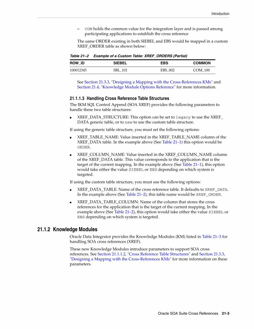
Introduction
Oracle SOA Suite Cross References 21-3
– COM holds the common value for the integration layer and is passed among participating applications to establish the cross reference
The same ORDER existing in both SIEBEL and EBS would be mapped in a custom XREF_ORDER table as shown below:
See Section 21.3.3, "Designing a Mapping with the Cross-References KMs" and Section 21.4, "Knowledge Module Options Reference" for more information.
21.1.1.3 Handling Cross Reference Table StructuresThe IKM SQL Control Append (SOA XREF) provides the following parameters to handle these two table structures:
■ XREF_DATA_STRUCTURE: This option can be set to legacy to use the XREF_DATA generic table, or to new to use the custom table structure.
If using the generic table structure, you must set the following options:
■ XREF_TABLE_NAME: Value inserted in the XREF_TABLE_NAME column of the XREF_DATA table. In the example above (See Table 21–1) this option would be ORDER.
■ XREF_COLUMN_NAME: Value inserted in the XREF_COLUMN_NAME column of the XREF_DATA table. This value corresponds to the application that is the target of the current mapping. In the example above (See Table 21–1), this option would take either the value SIEBEL or EBS depending on which system is targeted.
If using the custom table structure, you must use the following options:
■ XREF_DATA_TABLE: Name of the cross reference table. It defaults to XREF_DATA. In the example above (See Table 21–2), this table name would be XREF_ORDER.
■ XREF_DATA_TABLE_COLUMN: Name of the column that stores the cross references for the application that is the target of the current mapping. In the example above (See Table 21–2), this option would take either the value SIEBEL or EBS depending on which system is targeted.
21.1.2 Knowledge ModulesOracle Data Integrator provides the Knowledge Modules (KM) listed in Table 21–3 for handling SOA cross references (XREF).
These new Knowledge Modules introduce parameters to support SOA cross references. See Section 21.1.1.2, "Cross Reference Table Structures" and Section 21.3.3, "Designing a Mapping with the Cross-References KMs" for more information on these parameters.
Table 21–2 Example of a Custom Table: XREF_ORDERS (Partial)
ROW_ID SIEBEL EBS COMMON
100012345 SBL_101 EBS_002 COM_100

Introduction
21-4 Oracle Fusion Middleware Connectivity and Knowledge Modules Guide for Oracle Data Integrator
21.1.3 Overview of the SOA XREF KM ProcessTo load the cross reference tables while performing integration with Oracle Data Integrator, you must use the SOA XREF knowledge modules. These knowledge modules will load the cross reference tables while extracting or loading information across systems.
The overall process can be divided into the following three main phases:
1. Loading Phase (LKM)
2. Integration and Cross-Referencing Phase (IKM)
3. Updating/Deleting Processed Records (LKM)
21.1.3.1 Loading Phase (LKM)During the loading phase, a Source Primary Key is created using columns from the source table. This Source Primary Key is computed using a user-defined SQL expression that should return a VARCHAR value. This expression is specified in the SRC_PK_EXPRESSION KM option.
For example, for a source Order Line Table (aliased OLINE in the mapping) you can use the following expression:
TO_CHAR(OLINE.ORDER_ID) || '-' || TO_CHAR(OLINE.LINE_ID)
This value will be finally used to populate the cross reference table.
Table 21–3 SOA XREF Knowledge Modules
Knowledge Module Description
LKM SQL to SQL (SOA XREF) This KM replaces the LKM SQL to SQL (ESB XREF).
This KM supports cross references while loading data from a standard ISO source to any ISO-92 database.
Depending of the option SRC_UPDATE_DELETE_ACTION, this LKM can DELETE or UPDATE source records.
The LKM SQL to SQL (SOA XREF) has to be used in conjunction with the IKM SQL Control Append (SOA XREF) in the same mapping.
LKM MSSQL to SQL (SOA XREF) This KM replaces the LKM MSSQL to SQL (ESB XREF).
This KM is a version of the LKM SQL to SQL (SOA XREF) optimized for Microsoft SQL Server.
IKM SQL Control Append (SOA XREF) This KM replaces the IKM SQL Control Append (ESB XREF).
This KM provides support for cross references while integrating data in any ISO-92 compliant database target table in truncate/insert (append) mode. This KM provides also data control: Invalid data is isolated in an error table and can be recycled.
When loading data to the target, this KM also populates PK/GUID XREF table on a separate database.
This IKM SQL Control Append (SOA XREF) has to be used in conjunction with the LKM SQL to SQL (SOA XREF) or LKM MSSQL to SQL (SOA XREF).
Note: In order to maintain the cross referencing between source and target systems, the LKM and IKM supporting cross referencing must be used in conjunction.

Installation and Configuration
Oracle SOA Suite Cross References 21-5
21.1.3.2 Integration and Cross-Referencing Phase (IKM)During the integration phase, a Common ID is created for the target table. The value for the Common ID is computed from the expression in the XREF_SYS_GUID KM option. This expression can be for example:
■ A database sequence (<SEQUENCE_NAME>. NEXTVAL)
■ A function returning a global unique Id (SYS_GUID() for Oracle, NewID() for SQL Server)
This Common ID can also be automatically pushed to the target columns of the target table that are marked with the UD1 flag.
Both the Common ID and the Source Primary Key are pushed to the cross reference table. In addition, the IKM pushes to the cross reference table a unique Row Number value that creates the cross reference between the Source Primary Key and Common ID. This Row Number value is computed from the XREF_ROWNUMBER_EXPRESSION KM option, which takes typically expressions similar to the Common ID to generate a unique identifier.
The same Common ID is reused (and not re-computed) if the same source row is used to load several target tables across several mappings with the Cross-References KMs. This allows the creation of cross references between a unique source row and different targets rows.
21.1.3.3 Updating/Deleting Processed Records (LKM)This optional phase (parameterized by the SRC_UPDATE_DELETE_ACTION KM option) deletes or updates source records based on the successfully processed source records:
■ If SRC_UPDATE_DELETE_ACTION takes the DELETE value, the source records processed by the mapping are deleted.
■ If SRC_UPDATE_DELETE_ACTION takes the UPDATE value, a source column of the source table will be updated with an expression for all the processed source records. The following KM options parameterize this behavior:
– SRC_UPD_COL: Name of the source column to update
– SRC_UPD_COL_EXPRESSION: Expression used to generate the value to update in the column
It is possible to execute delete and update operations on a table different table from the source table. To do this, you must set the following KM options in the LKM:
■ SRC_PK_LOGICAL_SCHEMA: Oracle Data Integrator Logical schema containing the source table to impact.
■ SRC_PK_TABLE_NAME: Name of the source table to impact.
■ SRC_PK_TABLE_ALIAS: Table alias for this table.
21.2 Installation and ConfigurationMake sure you have read the information in this section before you start using the SOA XREF Knowledge Modules:
■ System Requirements and Certifications
■ Technology Specific Requirements
■ Connectivity Requirements

Working with XREF using the SOA Cross References KMs
21-6 Oracle Fusion Middleware Connectivity and Knowledge Modules Guide for Oracle Data Integrator
21.2.1 System Requirements and CertificationsBefore performing any installation you should read the system requirements and certification documentation to ensure that your environment meets the minimum installation requirements for the products you are installing.
The list of supported platforms and versions is available on Oracle Technical Network (OTN):
http://www.oracle.com/technology/products/oracle-data-integrator/index.html.
21.2.2 Technology Specific RequirementsThere are no technology requirements for using Oracle SOA Suite cross references in Oracle Data Integrator. The requirements for the Oracle Database and Microsoft SQl Server apply also to Oracle SOA Suite cross references. For more information, see:
■ Chapter 2, "Oracle Database"
■ Chapter 7, "Microsoft SQL Server"
21.2.3 Connectivity RequirementsThere are no connectivity requirements for using Oracle SOA Suite cross references in Oracle Data Integrator. The requirements for the Oracle Database and Microsoft SQl Server apply also to Oracle SOA Suite cross references. For more information, see:
■ Chapter 2, "Oracle Database"
■ Chapter 7, "Microsoft SQL Server"
21.3 Working with XREF using the SOA Cross References KMsThis section consists of the following topics:
■ Defining the Topology
■ Setting up the Project
■ Designing a Mapping with the Cross-References KMs
21.3.1 Defining the TopologyThe steps to create the topology in Oracle Data Integrator, which are specific to projects using SOA XREF KMs, are the following:
1. Create the data servers, physical and logical schemas corresponding to the sources and targets.
2. Create a data server and a physical schema for the Oracle or Microsoft SQL Server technology as described in the following sections:
■ Section 2.3.1, "Creating an Oracle Data Server" and Section 2.3.2, "Creating an Oracle Physical Schema"
■ Section 7.3.1, "Creating a Microsoft SQL Server Data Server" and Section 7.3.2, "Creating a Microsoft SQL Server Physical Schema"
This data server and this physical schema must point to the Oracle instance and schema or to the Microsoft SQL Server database containing the cross reference tables.

Working with XREF using the SOA Cross References KMs
Oracle SOA Suite Cross References 21-7
3. Create a logical schema called XREF pointing to the physical schema. containing the cross reference table.
See "Creating a Logical Schema" in the Developer's Guide for Oracle Data Integrator for more information.
21.3.2 Setting up the ProjectImport the following KMs into your project, if they are not already in your project:
■ IKM SQL Control Append (SOA XREF)
■ LKM SQL to SQL (SOA XREF) or LKM MSSQL to SQL (SOA XREF) if using Microsoft SQL Server
21.3.3 Designing a Mapping with the Cross-References KMsTo create a mapping, which both loads a target table from several source tables and handles cross references between one of the sources and the target, run the following steps:
1. Create a mapping with the source and target datastores which will have the cross references.
2. Create joins, filters and mappings as usual.
Mapping the Common ID: If you want to map in a target column the Common ID generated for the cross reference table, check the UD1 flag for this column and enter a dummy mapping. For example a constant value such as'X'.
3. In the Physical diagram of the mapping, select the access point for the execution unit containing the source table to cross reference. The Property Inspector for this object opens.
4. In the Loading Knowledge Module tab, select the LKM SQL to SQL (SOA XREF) or LKM MSSQL to SQL (SOA XREF) if the source data store is in Microsoft SQL Server.
5. Specify the KM options as follows:
■ Specify in SRC_PK_EXPRESSION the expression representing the Source Primary Key value that you want to store in the XREF table.
If the source table has just one attribute defined as a key, enter the attribute name (for example SEQ_NO).
If the source key has multiple attributes, specify the expression to use for deriving the key value. For example, if there are two key attributes SEQ_NO and DOC_DATE in the table and you want to store the concatenated value of those attributes as your source value in the XREF table enter SEQ_NO || DOC_DATE. This option is mandatory.
■ Optionally set the SRC_UPDATE_DELETE_ACTION to impact the source table, as described in Section 21.1.3.3, "Updating/Deleting Processed Records (LKM)"
6. In the Physical diagram of the mapping, select the access point for your staging area. The Property Inspector opens for this object.
7. In the Integration Knowledge Module tab, select the IKM SQL Control Append (SOA XREF).
8. Specify the KM options as follows:

Knowledge Module Options Reference
21-8 Oracle Fusion Middleware Connectivity and Knowledge Modules Guide for Oracle Data Integrator
■ XREF_DATA_STRUCTURE: Enter New to use the new XREF_DATA Table structure. Otherwise enter Legacy to use legacy XREF_DATA Table. Default is New. Configure the options depending on the table structure you are using, as specified in Section 21.1.1.3, "Handling Cross Reference Table Structures"
■ XREF_SYS_GUID_EXPRESSION: Enter the expression to be used to computing the Common ID. This expression can be for example:
– a database sequence (<SEQUENCE_NAME>.NEXTVAL)
– a function returning a global unique Id (SYS_GUID() for Oracle and NewID() for SQL Server)
■ XREF_ROWNUMBER_EXPRESSION: This is the value that is pushed into the Row Number column. Use the default value of GUID unless you have the need to change it to a sequence.
■ FLOW_CONTROL: Set to YES in order to be able to use the CKM Oracle.
21.4 Knowledge Module Options ReferenceThis section lists the KM options for the following Knowledge Modules:
■ LKM SQL to SQL (SOA XREF)
■ LKM MSSQL to SQL (SOA XREF)
■ IKM SQL Control Append (SOA XREF)
Note: If the target table doesn't have any placeholder for the Common ID and you are for example planning to populate the source identifier in one of the target attributes, you must use the standard mapping rules of ODI to indicate which source identifier to populate in which attribute.
If the target attribute that you want to load with the Common ID is a unique key of the target table, it needs to be mapped. You must put a dummy mapping on that attribute. At runtime, this dummy mapping will be overwritten with the generated common identifier by the integration knowledge module. Make sure to flag this target attribute with UD1.

Knowledge Module Options Reference
Oracle SOA Suite Cross References 21-9
Table 21–4 LKM SQL to SQL (SOA XREF)
Option Values Mandatory Description
SRC_UPDATE_DELETE_ACTION
NONE|UPDATE|DELETE
Yes Indicates what action to take on source records after integrating data into the target. See Section 21.1.3.3, "Updating/Deleting Processed Records (LKM)" for more information.
SRC_PK_EXPRESSION Concatenating expression
Yes Expression that concatenates values from the PK to have them fit in a single large varchar column. For example: for the source Orderline Table (aliased OLINE in the mapping) you can use expression:
TO_CHAR(OLINE.ORDER_ID) || '-' || TO_CHAR(OLINE.LINE_ID)
SRC_PK_LOGICAL_SCHEMA
Name of source table's logical schema
No Indicates the source table's logical schema. The source table is the one from which we want to delete or update records after processing them. This logical schema is used to resolve the actual physical schema at runtime depending on the Context. For example: ORDER_BOOKING. This option is required only when SRC_UPDATE_DELETE_ACTION is set to UPDATE or DELETE.
SRC_PK_TABLE_NAME Source table name, default is MY_TABLE
No Indicate the source table name of which we want to delete or update records after processing them. For example: ORDERS This option is required only when SRC_UPDATE_DELETE_ACTION is set to UPDATE or DELETE.
SRC_PK_TABLE_ALIAS Source table alias, default is
MY_ALIAS
No Indicate the source table's alias within this mapping. The source table is the one from which we want to delete or update records after processing them. For example: ORD. This option is required only when SRC_UPDATE_DELETE_ACTION is set to UPDATE or DELETE.
SRC_UPD_COL Aliased source column name
No Aliased source column name that holds the update flag indicator. The value of this column will be updated after integration when SRC_UPDATE_DELETE_ACTION is set to UPDATE with the expression literal SRC_UPD_EXPRESSION. The alias used for the column should match the one defined for the source table. For example: ORD.LOADED_FLAG. This option is required only when SRC_UPDATE_DELETE_ACTION is set to UPDATE.
SRC_UPD_EXPRESSION Literal or expression No Literal or expression used to update the SRC_UPD_COL. This value will be used to update this column after integration when SRC_UPDATE_DELETE_ACTION is set to UPDATE. For example: RECORDS PROCESSED. This option is required only when SRC_UPDATE_DELETE_ACTION is set to UPDATE.
DELETE_TEMPORARY_OBJECTS
Yes|No Yes Set this option to NO if you wish to retain temporary objects (files and scripts) after integration. Useful for debugging.

Knowledge Module Options Reference
21-10 Oracle Fusion Middleware Connectivity and Knowledge Modules Guide for Oracle Data Integrator
LKM MSSQL to SQL (SOA XREF)See Table 21–4 for details on the LKM MSSQL to SQL (SOA XREF) options.
Table 21–5 IKM SQL Control Append (SOA XREF)
Option Values Mandatory Description
INSERT Yes|No Yes Automatically attempts to insert data into the Target Datastore of the Mapping.
COMMIT Yes|No Yes Commit all data inserted in the target datastore.
FLOW_CONTROL Yes|No Yes Check this option if you wish to perform flow control.
RECYCLE_ERRORS Yes|No Yes Check this option to recycle data rejected from a previous control.
STATIC_CONTROL Yes|No Yes Check this option to control the target table after having inserted or updated target data.
TRUNCATE Yes|No Yes Check this option if you wish to truncate the target datastore.
DELETE_ALL Yes|No Yes Check this option if you wish to delete all the rows of the target datastore.
CREATE_TARG_TABLE Yes|No Yes Check this option if you wish to create the target table.
DELETE_TEMPORARY_OBJECTS
Yes|No Yes Set this option to NO if you wish to retain temporary objects (tables, files and scripts) after integration. Useful for debugging.
XREF_TABLE_NAME XREF table name Yes, if using Legacy XREF table structure.
Table Name to use in the XREF table. Example: ORDERS. See Section 21.1.1.3, "Handling Cross Reference Table Structures" for more information.
XREF_COLUMN_NAME Column name Yes, if using Legacy XREF table structure.
Primary key column name to use as a literal in the XREF table. See Section 21.1.1.3, "Handling Cross Reference Table Structures" for more information.
XREF_SYS_GUID_EXPRESSION
SYS_GUID() Yes Enter the expression used to populate the common ID for the XREF table (column name "VALUE"). Valid examples are: SYS_GUID(), MY_SEQUENCE.NEXTVAL, and so forth.
XREF_ROWNUMBER_EXPRESSION
SYS_GUID() Yes Enter the expression used to populate the row_number for the XREF table. For example for Oracle: SYS_GUID(), MY_SEQUENCE.NEXTVAL and so forth.

Knowledge Module Options Reference
Oracle SOA Suite Cross References 21-11
XREF_DATA_STRUCTURE
New|Legacy Yes Enter New to use the new XREF_DATA Table structure.. Otherwise enter Legacy to use legacy XREF_DATA Table. Default is New. See Section 21.1.1.3, "Handling Cross Reference Table Structures" for more information.
XREF_DATA_TABLE XREF table name No. Can be used with custom XREF table structure.
Enter the name of the table storing cross reference information. Default is XREF_DATA. See Section 21.1.1.3, "Handling Cross Reference Table Structures" for more information.
XREF_DATA_TABLE_COLUMN
XREF data table column name
Yes, if using custom XREF table structure
For new XREF data structure only: Enter the column name of the XREF data table to store the source key values. See Section 21.1.1.3, "Handling Cross Reference Table Structures" for more information.
Table 21–5 (Cont.) IKM SQL Control Append (SOA XREF)
Option Values Mandatory Description

Knowledge Module Options Reference
21-12 Oracle Fusion Middleware Connectivity and Knowledge Modules Guide for Oracle Data Integrator

Part IVPart IV Appendices
Part IV contains the following appendices:
■ Appendix A, "Oracle Data Integrator Driver for LDAP Reference"
■ Appendix B, "Oracle Data Integrator Driver for XML Reference"
■ Appendix C, "Oracle Data Integrator Driver for Complex Files Reference"


A
Oracle Data Integrator Driver for LDAP Reference A-1
AOracle Data Integrator Driver for LDAPReference
This appendix describes how to work with the Oracle Data Integrator driver for LDAP.
This appendix includes the following sections:
■ Section A.1, "Introduction to Oracle Data Integrator Driver for LDAP"
■ Section A.2, "LDAP Processing Overview"
■ Section A.3, "Installation and Configuration"
■ Section A.4, "SQL Syntax"
■ Section A.5, "JDBC API Implemented Features"
A.1 Introduction to Oracle Data Integrator Driver for LDAPWith Oracle Data Integrator Driver for LDAP (LDAP driver) Oracle Data Integrator is able to manipulate complex LDAP trees using standard SQL queries.
The LDAP driver supports:
■ Manipulation of LDAP entries, their object classes and attributes
■ Standard SQL (Structured Query Language) Syntax
■ Correlated subqueries, inner and outer joins
■ ORDER BY and GROUP BY
■ COUNT, SUM, MIN, MAX, AVG and other functions
■ All Standard SQL functions
■ Referential Integrity (foreign keys)
■ Persisting modifications into directories
A.2 LDAP Processing OverviewThe LDAP driver works in the following way:
1. The driver loads (upon connection) the LDAP structure and data into a relational schema, using a LDAP to Relational Mapping.
2. The user works on the relational schema, manipulating data through regular SQL statements. Any changes performed in the relational schema data (insert/update) are immediately impacted by the driver in the LDAP data.

LDAP Processing Overview
A-2 Oracle Fusion Middleware Connectivity and Knowledge Modules Guide for Oracle Data Integrator
A.2.1 LDAP to Relational MappingThe LDAP to Relational Mapping is a complex but automated process that is used to generate a relational structure. As LDAP servers do not provide metadata information in a standard way, this mapping is performed using data introspection from the LDAP tree. Therefore, automatic mapping is carried out on the contents of the LDAP tree used as a source for this process.
This section contains the following topics:
■ General Principle
■ Grouping Factor
■ Mapping Exceptions
■ Reference LDAP Tree
A.2.1.1 General PrincipleThe LDAP driver maps LDAP elements to a relational schema in the following way:
■ Each LDAP class or combination of classes is mapped to a table. Each entry from the LDAP tree is mapped to a record in the table.
■ Each attribute of the class instances is mapped to a column.
■ Hierarchical relationships between entries are mapped using foreign keys. A table representing a hierarchical level is created with a primary key called <tablename>PK. Records reference their parent tables through a <parent_level_tablename>FK column. The root of the LDAP tree structure is mapped to a table called ROOT containing a ROOTPK column in a unique record.
■ Attributes with multiple values for an entry (for example, a Person entry with several email attributes) are mapped as sub-tables called <parent_tablename><attribute_name>. Each sub-table contains a <parent_tablename>FK column linking it to the parent table.
Figure A–1 shows an LDAP tree with OrganizationalUnit entries linking to Person instances. In this case, certain Person entries have multiple email addresses.
Figure A–1 LDAP Tree Example
This LDAP tree will be mapped into the following relational structure:

LDAP Processing Overview
Oracle Data Integrator Driver for LDAP Reference A-3
■ The ROOT table represents the root of the hierarchy and contains one ROOTPK column.
■ The ORGANIZATIONALUNIT table represents different organizationalUnit instances of the tree. It contains the ORGANIZATIONALUNITPK primary key column and the attributes of the organizationalUnit instances (cn, telephoneNumber, etc.). It is linked to the ROOT table by the ROOTFK foreign key column.
■ The PERSON table represents the instances of the person class. It contains the PERSONPK primary key column and the ORGANIZATIONALUNITFK linking it to the ORGANIZATIONALUNIT table and the attributes of PERSON instances, (telephoneNumber, description, cn).
■ The email attribute appears as a PERSON_EMAIL table containing the EMAIL column and a PERSONFK linking a list of email attributes to a PERSON record.
Figure A–2 shows the resulting relational structure.
Figure A–2 Relational Structure mapped from the LDAP Tree Example shown in Figure A–1
A.2.1.2 Grouping FactorIn LDAP directories, class entries are often specified by inheriting attributes from multiple class definitions. In the relational mapping procedure, the LDAP driver translates this fact by combining each combination of classes in an LDAP entry to generate a new table.
For example, some entries of the Person class may also be instances of either of the Manager or BoardMember classes (or both). In this case, the mapping procedure would generate a PERSON table (for the instances of Person) but also MANAGER_PERSON, BOARDMEMBER_PERSON, BOARDMEMBER_MANAGER_PERSON and so forth, tables depending on the combination of classes existing in the LDAP tree.
In order to avoid unnecessary multiplication of generated tables, it is possible to parameterize this behavior. The Grouping Factor parameter allows this by defining the number of divergent classes below which the instances remain grouped together in the same table. This resulting table contains flag columns named IS_<classname>, whose values determine the class subset to which the instance belongs. For example, if IS_<classname> is set to 1, then the instance represented by the record belongs to <classname>.

LDAP Processing Overview
A-4 Oracle Fusion Middleware Connectivity and Knowledge Modules Guide for Oracle Data Integrator
The behavior where one table is created for each combination of classes corresponds to a Grouping Factor equal to zero. With a grouping factor equal to one, instances with only one divergent class remain in the same table.
In our example, with a Grouping Factor higher than or equal to 2, all company person instances (including Person, Manager and BoardMember class instances) are grouped in the PERSON table. The IS_MANAGER and IS_BOARDMEMBER columns enable the determination of PERSON records that are also in the Manager and/or BoardMember classes.
A.2.1.3 Mapping ExceptionsThis section details some specific situations of the mapping process.
■ Table name length limits and collisions: In certain cases, name-length restrictions may result in possible object name collisions. The LDAP driver avoids such situations by automatically generating 3 digit suffixes to the object name.
■ Key column: It is possible to have the driver automatically create an additional SNPSLDAPKEY column containing the Relative Distinguished Name (RDN) that can be used as identifier for the current record (original LDAP class instance). This is done by setting the key_column URL property to true. This SNPSLDAPKEY column must be loaded if performing DML commands that update the LDAP tree contents. Note that this column is created only in tables that originate from LDAP instances. Tables that correspond to multiple valued instance attributes will not be created with these columns.
■ Case sensitivity: This is set by the case_sens URL property that makes the RDBMS and LDAP servers to enforce case-sensitivity.
■ Special characters: It is possible in LDAP to have non-alphanumeric characters into attribute or class names. These characters are converted to underscores ("_") during the mapping. Exception: If non alphanumeric, the first character is converted to "x".
■ SQL Reversed Keywords: Generated tables and columns with names that match SQL keywords are automatically renamed (an underscore is added after their name) in the relational structure to avoid naming conflicts between table/column names and SQL keywords. For example, a class named SELECT will be mapped to a table named SELECT_.
A.2.1.4 Reference LDAP TreeAs LDAP servers do not provide metadata information in a standard way, the LDAP to Relational Mapping process is performed by default using data introspection from the LDAP tree.
With the LDAP driver it is also possible to use a Reference LDAP Tree for the LDAP to Relational Mapping process instead of using the LDAP tree that contains the actual data.
This Reference LDAP Tree is configured using the lm_props property of the driver URL. This property specifies a.properties file that contains the connection information to a LDAP tree whose hierarchical structure rigorously reflects that of the operational LDAP tree but without the accompanying data volume.
This technique reveals certain advantages:
■ The Reference LDAP Tree can be maintained by the directory administrator as a stable definition of the operational LDAP tree.
■ The Reference LDAP Tree contains few instances that make up the skeleton of the real LDAP tree, and the LDAP to Relational Mapping process runs faster on this

LDAP Processing Overview
Oracle Data Integrator Driver for LDAP Reference A-5
small reference tree. This is particularly important for large operational LDAP directories, and will result in reduced processing time and resources for running the procedure.
The use of this technique, however, imposes a certain number of constraints in the design of the precise structure of the Reference LDAP Tree:
■ All optional LDAP instance attributes must be instantiated in the reference entries. Even if these attributes are absent in the operational LDAP directory entries, they must be declared in the Reference LDAP Tree if they are to be used at a later time.
■ Any multiple valued attributes that exist in the operational LDAP directory must be instantiated as such in the Reference LDAP Tree. For example, if any Person instance in the operational LDAP directory possesses two telephoneNumber attributes, then the generic Person class must instantiate at least two telephoneNumber attributes in the Reference LDAP Tree.
A.2.2 Managing Relational SchemasThis section contains the following topics:
■ Relational Schema Storage
■ Accessing Data in the Relational Structure
A.2.2.1 Relational Schema StorageThe relational structure resulting from the LDAP to Relational mapping may be managed by virtual mapping or stored in an external database.
The virtual mapping stores the relational structure in the run-time agent's memory and requires no other component. The relational structure is transparently mapped by the driver to the LDAP tree structure. SQL commands and functions that are available for the LDAP driver are listed in the SQL Syntax.
The external database may be any relational database management system. The driver connects through JDBC to this engine and uses it to store the relational schema. This method provides the following benefits:
■ Processing and storage capabilities of the selected external database engine.
■ Acccess to the specific SQL statements, procedures, and functions of the external database engine.
■ Flexible persistence of the relational structure. This schema content may persist after the connection to the LDAP driver is closed.
See Section A.3.2, "Using an External Database to Store the Data" for more information on how to set up external storage.
Note: These issues have a direct impact on the generated relational structure by forcing the creation of additional tables and columns to map multiple attribute fields and must be taken into consideration when designing the Reference LDAP Tree.
Note: The virtual mapping may require a large amount of memory for large LDAP tree structures.

Installation and Configuration
A-6 Oracle Fusion Middleware Connectivity and Knowledge Modules Guide for Oracle Data Integrator
A.2.2.2 Accessing Data in the Relational StructureDML operations on tables in the relational are executed with standard SQL statements.
Modifications made to the relational data are propagated to the directory depending on the selected storage :
■ In the case where the virtual mapping is used, all insert, update, and delete requests are automatically propagated to the original LDAP server in an autocommit mode. No explicit COMMIT or ROLLBACK statements will have any impact on the Oracle Data Integrator driver for LDAP.
■ In the case where the external database is used to store the relational structure, all types of DML statements may be used with the driver. However, it is important to know that no modifications will be propagated to the original LDAP server.
A.3 Installation and Configuration The Oracle Data Integrator driver for LDAP is automatically installed during the Oracle Data Integrator installation. The following topics cover advanced configuration topics and reference information.
This section contains the following topics:
■ Driver Configuration
■ Using an External Database to Store the Data
■ LDAP Directory Connection Configuration
■ Table Aliases Configuration
A.3.1 Driver ConfigurationThis section details the driver configuration.
■ The driver name is: com.sunopsis.ldap.jdbc.driver.SnpsLdapDriver
■ The driver supports two URL formats:
■ jdbc:snps:ldap?<property=value>[&...]
■ jdbc:snps:ldap2?<property=value>[&...]
The first URL requires the LDAP directory password to be encoded. The second URL allows you to give the LDAP directory password without encoding it.
The LDAP driver uses different properties depending on the established connection. Figure A–3 shows when to use which properties.
Note: You must add the libraries and drivers required to connect the LDAP directory using JNDI to the Oracle Data Integrator classpath.
Note: If using an external database engine you must also make sure that the JDBC driver used to connect to the external database and the .properties file are in the classpath.
Note: It is recommended to use the first URL to secure the LDAP directory password.

Installation and Configuration
Oracle Data Integrator Driver for LDAP Reference A-7
Figure A–3 Properties Files for LDAP Driver
The LDAP driver connects to the LDAP directory. You can configure this connection with the properties that start with ldap_. For example, ldap_basedn. Instead of passing the LDAP directory properties in the driver URL, you can use a properties file for the configuration of the connection to the LDAP directory. This properties file must be specified in the ldap_props property of the driver URL.
If you want to use the hierarchical structure of the LDAP tree without the accompanying data volume, you can use the Reference LDAP tree. The connection to the Reference LDAP tree is configured with the properties that start with lm_. For example, lm_basedn. Instead of passing the lm_ properties in the driver URL, you can use a properties file. This properties file must be specified in the lm_props property of the driver URL. See Section A.2.1.4, "Reference LDAP Tree" for more information.
To configure the connection of the LDAP driver to an external database, use the properties that start with db_. For example, db_url. Instead of passing the external database properties in the driver URL, you can use a properties file for the configuration of the connection to the external database. This properties file must be specified in the db_props property of the driver URL. See Section A.3.2, "Using an External Database to Store the Data" for more information.
Table A–1 describes the properties that can be passed in the driver URL.

Installation and Configuration
A-8 Oracle Fusion Middleware Connectivity and Knowledge Modules Guide for Oracle Data Integrator
Table A–1 Driver Properties
Property Mandatory Type Default Description
db_props or dp
No string (file location)
Empty string
Name of a .properties file containing the external database connection configuration. See Section A.3.2, "Using an External Database to Store the Data" for the details of this file content.
Note: This property should contain the name of the .properties file without the file extension.
Note: This .properties file must be in the run-time agent classpath.
Note: You can specify the external database connection configuration using all the db_ properties listed below in this table.
ldap_props or lp
No string (file location)
N/A Name of a .properties file containing the directory connection configuration. See Section A.3.3, "LDAP Directory Connection Configuration" for the details of this file content.
Note: This property should contain the name of the .properties file without the file extension.
Note: This .properties file must be in the run-time agent classpath.
Note: You can specify the LDAP directory connection configuration using all the ldap_ properties listed below in this table.
lm_props or lm
No string (file location)
N/A Name of a .properties file containing the directory connection configuration for the Reference LDAP Tree. See Section A.3.3, "LDAP Directory Connection Configuration" for the details of this file content, and Section A.2.1.4, "Reference LDAP Tree" for an explanation of the reference tree.
Note: This property should contain the name of the .properties file without the file extension.
Note: This .properties file must be in the run-time agent classpath.
Note: You can specify the reference LDAP directory connection configuration using all the lm_ properties listed below in this table.
case_sens or cs
No boolean (true | false)
false Enable / disable case sensitive mode for both LDAP- and RDBMS-managed objects.
alias_bundle or ab
No string (file location)
Empty string
Full name of a properties file including both the absolute path to the properties file and the file extension. The properties file is a file that contains the list of aliases for the LDAP to Relational Mapping. If this file does not exist, it will be created by the driver. See Section A.3.4, "Table Aliases Configuration" for more information.
Note: The file extension does not need to be .properties.
alias_bundle_encoding or abe
No string (encoding code)
Default encoding
Alias bundle file encoding. This encoding is used while reading and overwriting the alias_bundle file. If it is not defined then the default encoding would be used.
You will find a list of supported encoding at the following URL: http://java.sun.com/j2se/1.3/docs/guide/intl/encoding.doc.html.
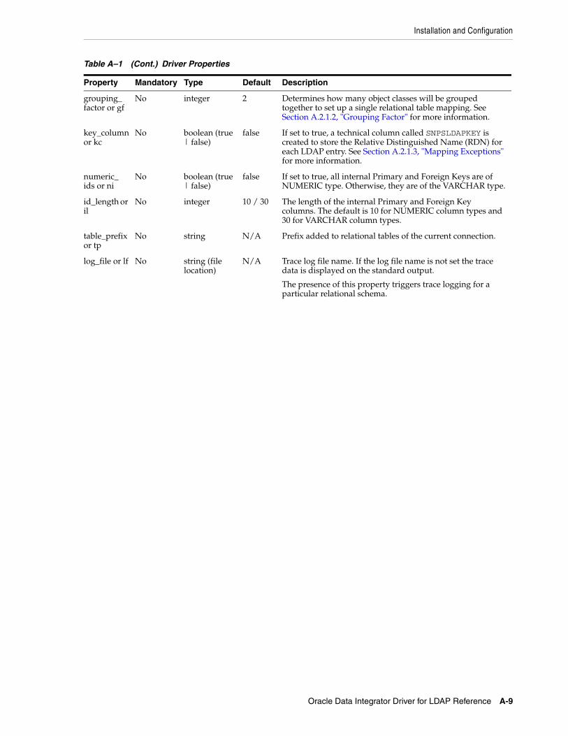
Installation and Configuration
Oracle Data Integrator Driver for LDAP Reference A-9
grouping_factor or gf
No integer 2 Determines how many object classes will be grouped together to set up a single relational table mapping. See Section A.2.1.2, "Grouping Factor" for more information.
key_column or kc
No boolean (true | false)
false If set to true, a technical column called SNPSLDAPKEY is created to store the Relative Distinguished Name (RDN) for each LDAP entry. See Section A.2.1.3, "Mapping Exceptions" for more information.
numeric_ids or ni
No boolean (true | false)
false If set to true, all internal Primary and Foreign Keys are of NUMERIC type. Otherwise, they are of the VARCHAR type.
id_length or il
No integer 10 / 30 The length of the internal Primary and Foreign Key columns. The default is 10 for NUMERIC column types and 30 for VARCHAR column types.
table_prefix or tp
No string N/A Prefix added to relational tables of the current connection.
log_file or lf No string (file location)
N/A Trace log file name. If the log file name is not set the trace data is displayed on the standard output.
The presence of this property triggers trace logging for a particular relational schema.
Table A–1 (Cont.) Driver Properties
Property Mandatory Type Default Description

Installation and Configuration
A-10 Oracle Fusion Middleware Connectivity and Knowledge Modules Guide for Oracle Data Integrator
log_level or ll
No integer 1 Log level. This property is ignored if log_file is not specified. The log level can is a bit mask that can be specified either in hexadecimal or decimal value.
Log Level Values:
■ 0x1 (1): General information (important)
■ 0x2 (2): General information (detailed)
■ 0x4 (4): SQL statements
■ 0x8 (8): LDAP-Relational mapping information
■ 0x10 (16): LDAP-Relational mapping validation & renaming information (Table and columns name modifications, etc)
■ 0x20 (32): Display the LDAP model parsed and the corresponding relational model.
■ 0x40 (64): Display the table creation statements.
■ 0x80 (128): Display data insert statements.
■ 0x100 (256): Grouping information (important)
■ 0x200 (512): Grouping information (detailed)
■ 0x400 (1024): Display details on the relational model building
■ 0x800 (2048): Display the elements read from the LDAP tree
■ 0x1000 (4096): Display SQL statements causing changes into the LDAP tree
Examples:
■ Important and detailed general information: log_level=3 (1+2)
■ Trace native SQL commands and important internal events: log_level=5 (1+4)
■ Trace relational mapping calculation and validation: log_level=24 (16+8)
■ Trace all events: log_level=8191 (1+2+ ... + 2048 + 4096)
ldap_auth No string simple LDAP Directory authentication method. See the auth property in Section A.3.3, "LDAP Directory Connection Configuration".
ldap_url Yes string N/A LDAP Directory URL. See the url property in Section A.3.3, "LDAP Directory Connection Configuration".
ldap_user No string Empty string
LDAP Directory user name. See the user property in Section A.3.3, "LDAP Directory Connection Configuration".
ldap_password
No string Empty string
LDAP Directory user password. See the password property in Section A.3.3, "LDAP Directory Connection Configuration".
ldap_basedn
No string N/A LDAP Directory basedn. See the basedn property in Section A.3.3, "LDAP Directory Connection Configuration".
lm_auth No string simple Reference LDAP authentication method. See the auth property in Section A.3.3, "LDAP Directory Connection Configuration".
lm_url Yes string N/A Reference LDAP URL. See the url property in Section A.3.3, "LDAP Directory Connection Configuration".
Table A–1 (Cont.) Driver Properties
Property Mandatory Type Default Description

Installation and Configuration
Oracle Data Integrator Driver for LDAP Reference A-11
URL ExamplesThe following section lists URL examples:
■ jdbc:snps:ldap?lp=ldap_mir&ldap_basedn=o=tests&gf=10&lf=
Connects to the LDAP directory specified in the ldap_mir .properties file, overriding the basedn property of the ldap bundle and using a grouping factor of 10. General information (important) is sent to the standard output.
■ jdbc:snps:ldap?lp=ldap_ours&lm=generic&ab=c:/tmp/aliases.txt&gf=10&kc=true
Connects to the LDAP directory using the ldap_ours .properties file; a generic Directory tree for relational model creation is signaled by the lm property; an alias bundle file is used for the creation of the relational structure; a maximum
lm_user No string Empty string
Reference LDAP Directory user name. See the user property in Section A.3.3, "LDAP Directory Connection Configuration".
lm_password
No string Empty string
Reference LDAP Directory user password. See the password property in Section A.3.3, "LDAP Directory Connection Configuration".
lm_basedn No string N/A Reference LDAP Directory basedn. See the basedn property in Section A.3.3, "LDAP Directory Connection Configuration".
db_driver Yes string N/A External Database JDBC Driver. See the driver property in Section A.3.2, "Using an External Database to Store the Data".
db_url Yes string N/A External Database JDBC URL. See the url property in Section A.3.2, "Using an External Database to Store the Data".
db_user No string Empty string
External Database user. See the user property in Section A.3.2, "Using an External Database to Store the Data".
db_password
No string Empty string
External Database password. See the password property in Section A.3.2, "Using an External Database to Store the Data".
db_schema No string Empty string
External Database schema. See the schema property in Section A.3.2, "Using an External Database to Store the Data".
db_catalog No string Empty string
External Database catalog. See the catalog property in Section A.3.2, "Using an External Database to Store the Data".
db_drop_on_disconnect or db_dod
No boolean (true|false)
true Drop tables on disconnect on the external database. See the drop_on_disconnect property in Section A.3.2, "Using an External Database to Store the Data".
db_load_mode or db_lm
No string ci Loading method for the external database. See the load_mode property in Section A.3.2, "Using an External Database to Store the Data".
tna No boolean (true|false)
true Transform Non Ascii. Set to false to keep non-ascii characters.
Table A–1 (Cont.) Driver Properties
Property Mandatory Type Default Description

Installation and Configuration
A-12 Oracle Fusion Middleware Connectivity and Knowledge Modules Guide for Oracle Data Integrator
grouping factor of 10 is used; key column creation is enabled for the SNPSLDAPKEY field to allow updates requests in the relational model.
■ jdbc:snps:ldap?lp=ldap_mir&dp=mysql_mir_ldap&ldap_basedn=dc=tests&lm=ldap_mir&lm_basedn=dc=model&ab=d:/temp/mapldap.txt&
Connects to the LDAP directory using the ldap_mir .properties file; overriding ldap basedn property; using the "dc=model" subtree of the same directory to perform mapping; using an alias bundle; overriding the lm database property (load mode); specifying a grouping factor of 0 to indicate no grouping (grouping disabled); Full trace logging is activated.
■ Connects to a LDAP directory on the hydraroid machine. The LDAP server connection information - url, base dn, user and password - is specified in the URL using the ldap_xxx properties.
jdbc:snps:ldap?ldap_url=ldap://hydraroid:389/dc=localhost,dc=localdomain&ldap_password=KPLEKFMJKCLFJMDFDDGPGPDB&ldap_user=cn=orcladmin&ldap_basedn=ou=applications
A.3.2 Using an External Database to Store the DataThe relational structure resulting from the LDAP to relational mapping of the LDAP tree can be stored in the run-time agent's memory or in an external database.
The external storage is configured with a set of properties described in Table A–2.
The external storage properties can be passed in several ways:
■ Passing the Properties in the Driver URL
■ Setting the Properties in ODI Studio
■ Setting the Properties in a Properties File
A.3.2.1 Passing the Properties in the Driver URLThe properties can be directly set in the driver URL. When using this method, the properties have to be prefixed with db_ . For example, if connecting to an Oracle database, specify the Oracle JDBC driver name in the driver parameter as follows:
db_driver=oracle.jdbc.driver.OracleDriver.
A.3.2.2 Setting the Properties in ODI StudioThe properties can be specified on the Properties tab of the Data Server editor in Topology Navigator. When using this method, the properties have to be prefixed with db_. For example, if you want to set the driver parameter:
1. In the Key column, enter db_driver
2. In the Value column, enter oracle.jdbc.driver.OracleDriver if you are connecting to an Oracle database.
Note: The list of technologies that support external storage is available on Oracle Technical Network (OTN) :
http://www.oracle.com/technology/software/products/ias/files/fusion_certification.html

Installation and Configuration
Oracle Data Integrator Driver for LDAP Reference A-13
A.3.2.3 Setting the Properties in a Properties FileThe properties can be set in an external database properties file. This properties file, also called property bundle, is a text file with the .properties extension containing a set of lines with on each line a <property>=<value> pair.
This external database porperties file contains the properties of a JDBC connection to the relational database schema. The properties file is referenced using the db_props property in the JDBC URL.
When using this method, note the following:
■ The properties in the properties file are not prefixed and used as described in Table A–2.
■ The db_props property is set to the name of the properties file without the .properties extension. For example, if you have in your classpath the prod_directory.properties file, you should refer to this file as follows: db_props=prod_directory.
The db_props property indicates that the schema must be loaded in a database schema whose connection information is stored in a external database properties file.
■ The properties files have to be deployed by the agent using the LDAP connection. The location the properties file depends on the agent you are using:
– Local agent (Studio): Place the external DB properties file in the <user.dir>/odi/oracledi/userlib folder
– Standalone Agent: Place the external DB properties file in oracledi/agent/drivers folder
– JavaEE Agent: The external DB properties file should be packed into a JAR or ZIP file and added to the template generated by the Java EE agent. See "Deploying an Agent in a Java EE Application Server (Oracle WebLogic Server)" in the Developer's Guide for Oracle Data Integrator for more information.
■ When using property bundle files, you must make sure that the property bundle is present in the Oracle Data Integrator classpath. Typically, you should install this bundle in the drivers directories.
It is possible to set or override the external database properties on the URL. These properties must be prefixed with the string db_. For example:
jdbc:snps:ldap?ldap_url=ldap://localhost:389/&ldap_basedn=o=company&db_driver=oracle.jdbc.driver.OracleDriver&db_url=<external_db_url>
The properties for configuring external storage are described inTable A–2.
Note: It is important to understand that the LDAP driver loads external property bundle files once only at runtime startup. If errors occur in these files, it is advisable to exit Oracle Data Integrator and then reload it before re-testing.
Note: When connecting to the external database, the LDAP driver uses JDBC connectivity. Make sure that the JDBC driver to access this external database is also available in the ODI classpath.
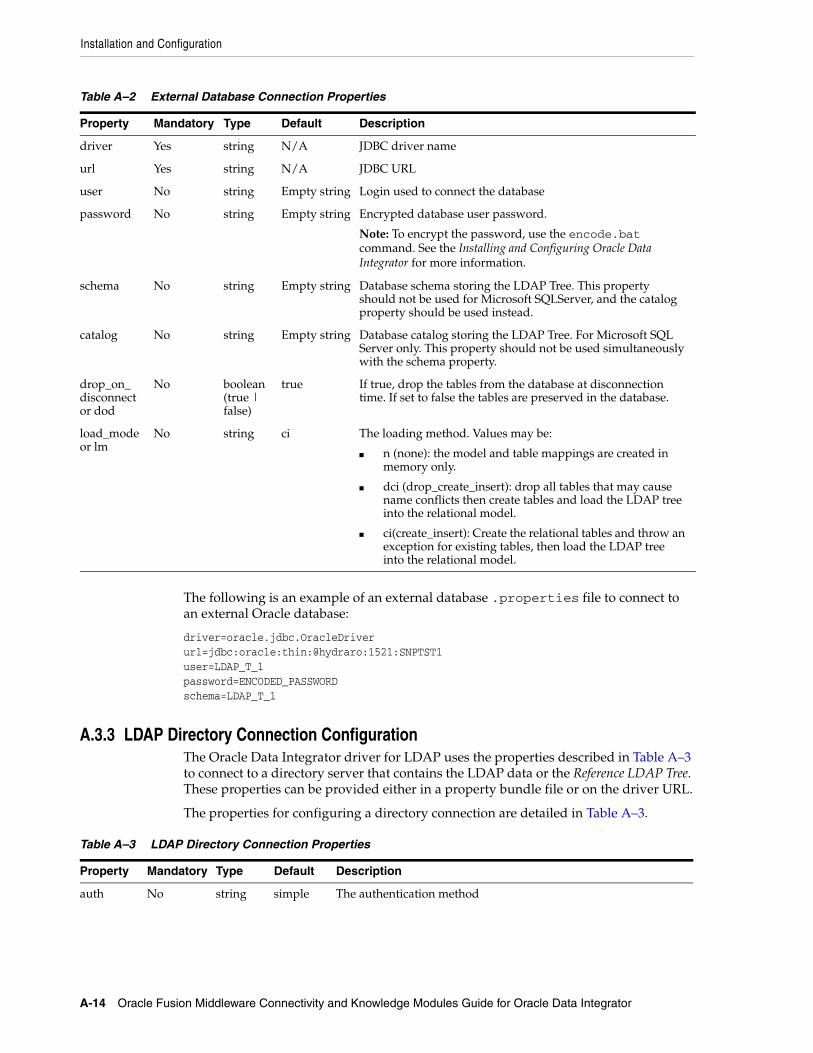
Installation and Configuration
A-14 Oracle Fusion Middleware Connectivity and Knowledge Modules Guide for Oracle Data Integrator
The following is an example of an external database .properties file to connect to an external Oracle database:
driver=oracle.jdbc.OracleDriverurl=jdbc:oracle:thin:@hydraro:1521:SNPTST1user=LDAP_T_1password=ENCODED_PASSWORDschema=LDAP_T_1
A.3.3 LDAP Directory Connection ConfigurationThe Oracle Data Integrator driver for LDAP uses the properties described in Table A–3 to connect to a directory server that contains the LDAP data or the Reference LDAP Tree. These properties can be provided either in a property bundle file or on the driver URL.
The properties for configuring a directory connection are detailed in Table A–3.
Table A–2 External Database Connection Properties
Property Mandatory Type Default Description
driver Yes string N/A JDBC driver name
url Yes string N/A JDBC URL
user No string Empty string Login used to connect the database
password No string Empty string Encrypted database user password.
Note: To encrypt the password, use the encode.bat command. See the Installing and Configuring Oracle Data Integrator for more information.
schema No string Empty string Database schema storing the LDAP Tree. This property should not be used for Microsoft SQLServer, and the catalog property should be used instead.
catalog No string Empty string Database catalog storing the LDAP Tree. For Microsoft SQL Server only. This property should not be used simultaneously with the schema property.
drop_on_disconnect or dod
No boolean (true | false)
true If true, drop the tables from the database at disconnection time. If set to false the tables are preserved in the database.
load_mode or lm
No string ci The loading method. Values may be:
■ n (none): the model and table mappings are created in memory only.
■ dci (drop_create_insert): drop all tables that may cause name conflicts then create tables and load the LDAP tree into the relational model.
■ ci(create_insert): Create the relational tables and throw an exception for existing tables, then load the LDAP tree into the relational model.
Table A–3 LDAP Directory Connection Properties
Property Mandatory Type Default Description
auth No string simple The authentication method

Installation and Configuration
Oracle Data Integrator Driver for LDAP Reference A-15
The following is an example of an LDAP properties file content:
url=ldap://ours:389user=cn=Directory Managerpassword=ENCODED_PASSWORDbasedn=dc=oracle,dc=com
A.3.4 Table Aliases ConfigurationThe LDAP driver allows a certain flexibility in the definition of the model table names in Oracle Data Integrator by the use of table aliases. This is particularly useful when the algorithm used to navigate the LDAP tree generates long composite names from the LDAP object class hierarchy. To avoid issues related to RDBMS-specific object name-length constraints, the LDAP driver can set up and use aliases.
To create a table alias file:
1. In the LDAP Driver Data Server URL, include and set the alias_bundle (ab) property that indicates the name of the alias text file, for example:
jdbc:snps:ldap?.....&ab=C:/tmp/aliases.txt&....
The alias file is created by the driver at connection time when the alias_bundle property is specified. Typically, a user connects initially through the LDAP driver which creates this file containing a list of potential table names to be created by the reverse-engineering operation.
url Yes string N/A URL to connect to the directory. It is an LDAP URL.
Note: This driver supports the LDAPS (LDAP over SSL) protocol. The LDAPS URL must start with ldaps://. To connect a server using LDAPS, you must manually install the certificate in the java machine. See the keytool program provided with the JVM for more information.
user No string Empty string
The LDAP server user-login name. Mandatory only if "auth" is set.
Note: If user and password properties are provided to create the connection with the JDBC Driver for LDAP, then they are used to connect the LDAP directory.
password No string Empty string
LDAP server user-login password. Mandatory only if "auth" is set.
Note: The password needs to be encrypted, unless the 'jdbc:snps:ldap2' URL syntax.
Note: To encrypt the password, use the encode.bat command. See the Installing and Configuring Oracle Data Integrator for more information.
basedn No string N/A The base dn with which you wish to connect to the LDAP tree. The base dn is the top level of the LDAP directory tree. If it not specified, the base dn specified in the LDAP URL is used.
Note: It is also possible to change the default "Maximum Table Name Length" and "Maximum Column Name Length" values on the Others tab of the Technology Editor in the Physical Architecture accordion.
Table A–3 (Cont.) LDAP Directory Connection Properties
Property Mandatory Type Default Description

SQL Syntax
A-16 Oracle Fusion Middleware Connectivity and Knowledge Modules Guide for Oracle Data Integrator
2. Test the connection to the LDAP data server.
3. Verify the that the text file has been created and has the expected structure. The list consists of <original table name > = <desired alias name> values. Example A–1 shows an extract of an alias file after the user has provided shortened names. See step 4 for more information.
Example A–1 Alias File
INETORGPERSON_ORGANIZATIONALPERSON_PERSON_BISOBJECT_MAIL = PERSONMAILORGANIZATIONALUNIT_RFC822MAILMEMBER = ORG_228MAILINETORGPERSON_ORGANIZATIONALPERSON_PERSON = ORG_PERSONORGANIZATIONALUNIT_MEMBER = ORG_UN_MEMBERORGANIZATIONALUNIT = ORG_UNITROOT = ROOT.... 4. In the alias text file, add short text value aliases to replace the originally derived
composite names and save the file.
5. Reconnect to the same LDAP data server. The relational schema is created and this time the aliases will be used for defining relational table names.
6. Now reverse-engineer the LDAP directory as described in Section 17.5.2, "Reverse-Engineering an LDAP Model". Oracle Data Integrator will create datastores with the table names defined as aliases in the alias file.
A.4 SQL SyntaxThe SQL statements described in Section A.4.1, "SQL Statements" are available when using the Oracle Data Integrator driver for LDAP. They enable the management of relational data structure and data through standard SQL Syntax.
Table A–4 summarizes the recommendations to apply when performing the listed DML operations on specific key fields.
Note: If any modifications have been applied to the object class structure or attribute sets of the LDAP directory, the driver will rewrite this file while including the new or modified entries to the table name list.
Note:
■ If you are using an external database you may use its proprietary query engine syntax in place of the following commands.
■ The LDAP driver works uniquely in auto commit mode. No explicit transaction management with COMMIT or ROLLBACK commands is permitted.
■ When using an external database to store LDAP tree data, DDL statements may only be carried out on temporary tables.

SQL Syntax
Oracle Data Integrator Driver for LDAP Reference A-17
A.4.1 SQL StatementsAny number of commands may be combined. The semicolon (;) may be used to separate each command but is not necessary.
A.4.1.1 DISCONNECTDISCONNECT
Closes this connection.
Remarks■ It is not required to call this command when using the JDBC interface: it is called
automatically when the connection is closed.
■ After disconnecting, it is not possible to execute other queries with this connection.
A.4.1.2 INSERT INTOInsert one or more new rows of data into a table.
INSERT INTO <table_name> [ ( <column_name> [,...] ) ] { VALUES (<expression> [,...]) | <SELECT Statement> }
A.4.1.3 SELECTRetrieves information from one or more tables in the schema.
SELECT [DISTINCT] { <select_expression> | <table_name>.* | * } [, ... ] [ INTO <new_table> ] FROM <table_list> [ WHERE <expression> ] [ GROUP BY <expression> [, ...] ] [ ORDER BY <order_expression> [, ...] ] [ { UNION [ALL] | {MINUS|EXCEPT} | INTERSECT } <select_statement> ]<table_list> ::=<table_name> [ { INNER | LEFT [OUTER] } JOIN <table_name> ON <expression> ] [, ...]
<select_expression> ::=
Table A–4 DML Opertaions on Key Fields
Type of Column Insert Update Delete
Foreign Key Pay attention to master table referential constraints and ordered table populate operations.
Not permitted Pay attention to master table referential constraints and ordered delete requests.
Primary Key Pay attention to slave table referential constraints and ordered table populate operations.
Not permitted Pay attention to slave table referential constraints and ordered delete requests
IS_xxx Pay attention to associating the correct flag value to the original object class.
Not permitted OK
Key_Column Pay attention to setting the RDN value in the correct LDAP syntax.
Not permitted OK
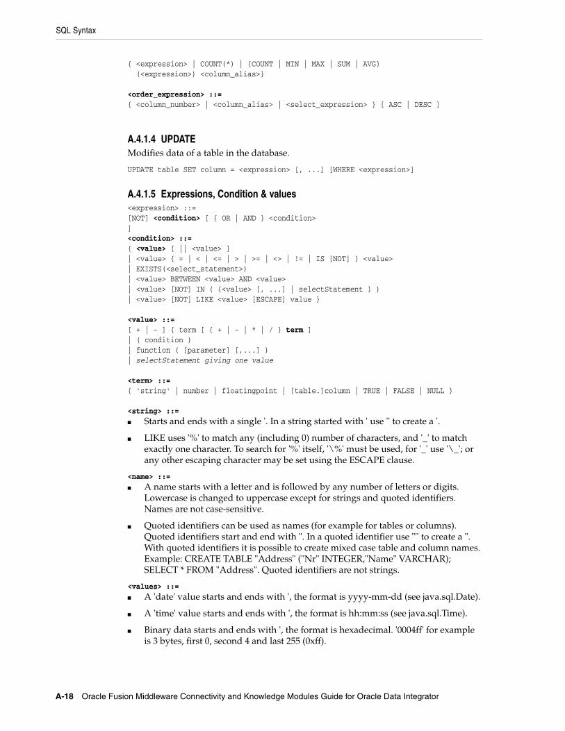
SQL Syntax
A-18 Oracle Fusion Middleware Connectivity and Knowledge Modules Guide for Oracle Data Integrator
{ <expression> | COUNT(*) | {COUNT | MIN | MAX | SUM | AVG} (<expression>) <column_alias>}
<order_expression> ::={ <column_number> | <column_alias> | <select_expression> } [ ASC | DESC ]
A.4.1.4 UPDATEModifies data of a table in the database.
UPDATE table SET column = <expression> [, ...] [WHERE <expression>]
A.4.1.5 Expressions, Condition & values<expression> ::=[NOT] <condition> [ { OR | AND } <condition> ]<condition> ::={ <value> [ || <value> ]| <value> { = | < | <= | > | >= | <> | != | IS [NOT] } <value>| EXISTS(<select_statement>)| <value> BETWEEN <value> AND <value>| <value> [NOT] IN ( {<value> [, ...] | selectStatement } )| <value> [NOT] LIKE <value> [ESCAPE] value }
<value> ::=[ + | - ] { term [ { + | - | * | / } term ]| ( condition )| function ( [parameter] [,...] )| selectStatement giving one value
<term> ::={ 'string' | number | floatingpoint | [table.]column | TRUE | FALSE | NULL }
<string> ::=■ Starts and ends with a single '. In a string started with ' use '' to create a '.
■ LIKE uses '%' to match any (including 0) number of characters, and '_' to match exactly one character. To search for '%' itself, '\%' must be used, for '_' use '\_'; or any other escaping character may be set using the ESCAPE clause.
<name> ::=■ A name starts with a letter and is followed by any number of letters or digits.
Lowercase is changed to uppercase except for strings and quoted identifiers. Names are not case-sensitive.
■ Quoted identifiers can be used as names (for example for tables or columns). Quoted identifiers start and end with ". In a quoted identifier use "" to create a ". With quoted identifiers it is possible to create mixed case table and column names. Example: CREATE TABLE "Address" ("Nr" INTEGER,"Name" VARCHAR); SELECT * FROM "Address". Quoted identifiers are not strings.
<values> ::=■ A 'date' value starts and ends with ', the format is yyyy-mm-dd (see java.sql.Date).
■ A 'time' value starts and ends with ', the format is hh:mm:ss (see java.sql.Time).
■ Binary data starts and ends with ', the format is hexadecimal. '0004ff' for example is 3 bytes, first 0, second 4 and last 255 (0xff).

SQL Syntax
Oracle Data Integrator Driver for LDAP Reference A-19
A.4.2 SQL FUNCTIONSTable A–5 describes the numeric functions.
Table A–6 describes the string functions.
Table A–5 Numeric Functions
Function Description
ABS(d) returns the absolute value of a double value
ACOS(d) returns the arc cosine of an angle
ASIN(d) returns the arc sine of an angle
ATAN(d) returns the arc tangent of an angle
ATAN2(a,b) returns the tangent of a/b
BITAND(a,b) returns a & b
BITOR(a,b) returns a | b
CEILING(d) returns the smallest integer that is not less than d
COS(d) returns the cosine of an angle
COT(d) returns the cotangent of an angle
DEGREES(d) converts radians to degrees
EXP(d) returns e (2.718...) raised to the power of d
FLOOR(d) returns the largest integer that is not greater than d
LOG(d) returns the natural logarithm (base e)
LOG10(d) returns the logarithm (base 10)
MOD(a,b) returns a modulo b
PI() returns pi (3.1415...)
POWER(a,b) returns a raised to the power of b
RADIANS(d) converts degrees to radians
RAND() returns a random number x bigger or equal to 0.0 and smaller than 1.0
ROUND(a,b) rounds a to b digits after the decimal point
SIGN(d) returns -1 if d is smaller than 0, 0 if d==0 and 1 if d is bigger than 0
SIN(d) returns the sine of an angle
SQRT(d) returns the square root
TAN(d) returns the trigonometric tangent of an angle
TRUNCATE(a,b) truncates a to b digits after the decimal point
Table A–6 String Functions
Function Description
ASCII(s) returns the ASCII code of the leftmost character of s
BIT_LENGTH(s) returns the string length in bits
CHAR(c) returns a character that has the ASCII code c
CHAR_LENGTH(s) returns the string length in characters

SQL Syntax
A-20 Oracle Fusion Middleware Connectivity and Knowledge Modules Guide for Oracle Data Integrator
Table A–7 describes the date and time functions.
CONCAT(str1,str2) returns str1 + str2
DIFFERENCE(s1,s2) returns the difference between the sound of s1 and s2
HEXTORAW(s1) returns the string translated from hexadecimal to raw
INSERT(s,start,len,s2) returns a string where len number of characters beginning at start has been replaced by s2
LCASE(s) converts s to lower case
LEFT(s,count) returns the leftmost count of characters of s
LENGTH(s) returns the number of characters in s
LOCATE(search,s,[start]) returns the first index (1=left, 0=not found) where search is found in s, starting at start
LTRIM(s) removes all leading blanks in s
OCTET_LENGTH(s) returns the string length in bytes
RAWTOHEX(s) returns translated string
REPEAT(s,count) returns s repeated count times
REPLACE(s,replace,s2) replaces all occurrences of replace in s with s2
RIGHT(s,count) returns the rightmost count of characters of s
RTRIM(s) removes all trailing blanks
SOUNDEX(s) returns a four character code representing the sound of s
SPACE(count) returns a string consisting of count spaces
SUBSTR(s,start[,len]) (alias for substring)
SUBSTRING(s,start[,len]) returns the substring starting at start (1=left) with length len.
Another syntax is SUBSTRING(s FROM start [FOR len])
TRIM TRIM([{LEADING | TRAILING | BOTH}] FROM s): removes trailing and/or leading spaces from s.
UCASE(s) converts s to upper case
LOWER(s) converts s to lower case
UPPER(s) converts s to upper case
Table A–7 Date and Time Functions
Function Description
CURDATE() returns the current date
CURTIME() returns the current time
CURRENT_DATE returns the current date
CURRENT_TIME returns the current time
CURRENT_TIMESTAMP returns the current timestamp
Table A–6 (Cont.) String Functions
Function Description

SQL Syntax
Oracle Data Integrator Driver for LDAP Reference A-21
Note that A date value starts and ends with ', the format is yyyy-mm-dd (see java.sql.Date). A time value starts and ends with ', the format is hh:mm:ss (see java.sql.Time).
Table A–8 describes the system functions.
Table A–9 describes the system and connection functions.
DATEDIFF(s, d1,d2) returns the counts of unit of times specified in s elapsed from datetime d1 to datetime d2. s may take the following values: 'ms'='millisecond', 'ss'='second','mi'='minute','hh'='hour', 'dd'='day', 'mm'='month', 'yy' = 'year'.
DAYNAME(date) returns the name of the day
DAYOFMONTH(date) returns the day of the month (1-31)
DAYOFWEEK(date) returns the day of the week (1 means Sunday)
DAYOFYEAR(date) returns the day of the year (1-366)
EXTRACT EXTRACT ({YEAR | MONTH | DAY | HOUR | MINUTE | SECOND} FROM <datetime>): extracts the appropriate part from the <datetime> value.
HOUR(time) return the hour (0-23)
MINUTE(time) returns the minute (0-59)
MONTH(date) returns the month (1-12)
MONTHNAME(date) returns the name of the month
NOW() returns the current date and time as a timestamp
QUARTER(date) returns the quarter (1-4)
SECOND(time) returns the second (0-59)
WEEK(date) returns the week of this year (1-53)
YEAR(date) returns the year
Table A–8 System Functions
Function Description
IFNULL(exp,value) if exp is null, value is returned else exp
CASEWHEN(exp,v2,v2) if exp is true, v1 is returned, else v2
CONVERT(term,type) converts exp to another data type
COALESCENCE(e1,e2,e3,...) if e1 is not null then it is returned, else e2 is evaluated. If e2 is null, then is it returned, else e3 is evaluated and so on.
NULLIF(v1,v2) returns v1 if v1 is not equal to v2, else returns null
CASE WHEN There are two syntax for the CASE WHEN statement:
CASE v1 WHEN v2 THEN v3 [ELSE v4] END: if v1 equals v2 then returns v3 [otherwise v4 or null if ELSE is not specified].
CASE WHEN e1 THEN v1[WHEN e2 THEN v2] [ELSE v4] END: when e1 is true return v1 [optionally repeated for more cases] [otherwise v4 or null if there is no ELSE]
CAST(term AS type) converts exp to another data type
Table A–7 (Cont.) Date and Time Functions
Function Description

JDBC API Implemented Features
A-22 Oracle Fusion Middleware Connectivity and Knowledge Modules Guide for Oracle Data Integrator
A.5 JDBC API Implemented FeaturesTable A–10 lists the JDBC API features of the Oracle Data Integrator driver for LDAP.
The following table identifies the JDBC classes supported by the Oracle Data Integrator driver for LDAP.
Table A–9 System and Connection Functions
Function Description
DATABASE() returns the name of the database of this connection
USER() returns the user name of this connection
IDENTITY() returns the last identity values that was inserted by this connection
Table A–10 JDBC API Features
Feature Groups JDBC Version Support
Batch Update 2.0 Core Yes
Blob/Clob 2.0 Core No
JNDI DataSources 2.0 Optional No
Failover support - No
Transaction SavePoints 3.0 No
Unicode support - No
Disributed Transaction 2.0 Optional No
Connection Pooling 2.0 Optional No
Cluster support - No
Table A–11 JDBC Classes
JDBC Classes JDBC Version Support
Array 2.0 Core No
Blob 2.0 Core No
Clob 2.0 Core No
CallableStatement 1.0 Yes
Connection 1.0 Yes
ConnectionPoolDataSource 2.0 Optional No
DatabaseMetaData 1.0 Yes
DataSource 2.0 Optional No
Driver 1.0 Yes
PreparedStatement 1.0 Yes
Ref 2.0 Core No
RowSet 2.0 Optional No
ResultSet 1.0 Yes
ResultSetMetaData 1.0 Yes
Statement 1.0 Yes

JDBC API Implemented Features
Oracle Data Integrator Driver for LDAP Reference A-23
Struct 2.0 Core No
XAConnection 2.0 Optional No
XADataSource 2.0 Optional No
Table A–11 (Cont.) JDBC Classes
JDBC Classes JDBC Version Support

JDBC API Implemented Features
A-24 Oracle Fusion Middleware Connectivity and Knowledge Modules Guide for Oracle Data Integrator

B
Oracle Data Integrator Driver for XML Reference B-1
BOracle Data Integrator Driver for XMLReference
This appendix describes how to work with the Oracle Data Integrator driver for XML.
This appendix includes the following sections:
■ Section B.1, "Introduction to Oracle Data Integrator Driver for XML"
■ Section B.2, "XML Processing Overview"
■ Section B.3, "Installation and Configuration"
■ Section B.4, "Detailed Driver Commands"
■ Section B.5, "SQL Syntax"
■ Section B.6, "JDBC API Implemented Features"
■ Section B.7, "XML Schema Supported Features"
B.1 Introduction to Oracle Data Integrator Driver for XMLOracle Data Integrator Driver for XML (XML driver) handles an XML document as a JDBC data source. This allows Oracle Data Integrator to use XML documents as data servers.
With Oracle Data Integrator Driver for XML, Oracle Data Integrator can query XML documents using standard SQL syntax and perform changes in the XML files. These operations occur within transactions and can be committed or rolled back.
The Oracle Data Integrator driver for XML supports the following features:
■ Standard SQL (Structured Query Language) Syntax
■ Correlated subqueries, inner and outer joins
■ ORDER BY and GROUP BY
■ COUNT, SUM, MIN, MAX, AVG and other functions
■ Standard SQL functions
■ Transaction Management
■ Referential Integrity (foreign keys)
■ Saving Changes made on XML data into the XML files
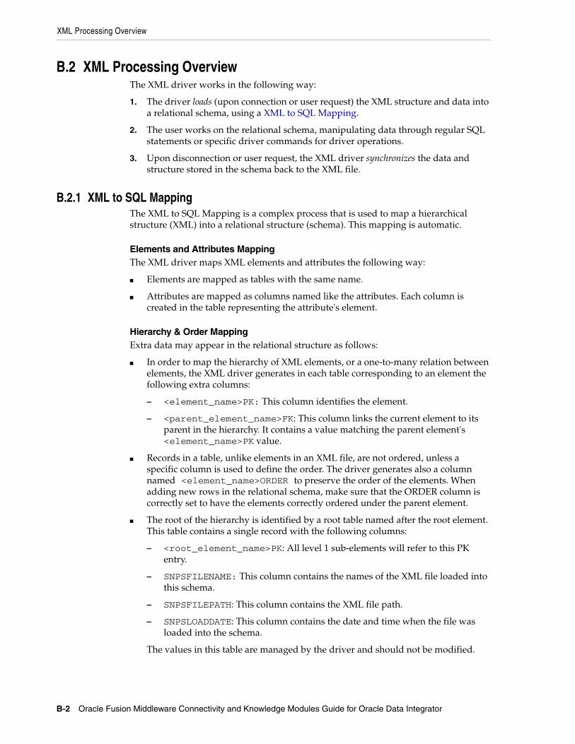
XML Processing Overview
B-2 Oracle Fusion Middleware Connectivity and Knowledge Modules Guide for Oracle Data Integrator
B.2 XML Processing OverviewThe XML driver works in the following way:
1. The driver loads (upon connection or user request) the XML structure and data into a relational schema, using a XML to SQL Mapping.
2. The user works on the relational schema, manipulating data through regular SQL statements or specific driver commands for driver operations.
3. Upon disconnection or user request, the XML driver synchronizes the data and structure stored in the schema back to the XML file.
B.2.1 XML to SQL MappingThe XML to SQL Mapping is a complex process that is used to map a hierarchical structure (XML) into a relational structure (schema). This mapping is automatic.
Elements and Attributes MappingThe XML driver maps XML elements and attributes the following way:
■ Elements are mapped as tables with the same name.
■ Attributes are mapped as columns named like the attributes. Each column is created in the table representing the attribute's element.
Hierarchy & Order Mapping Extra data may appear in the relational structure as follows:
■ In order to map the hierarchy of XML elements, or a one-to-many relation between elements, the XML driver generates in each table corresponding to an element the following extra columns:
– <element_name>PK: This column identifies the element.
– <parent_element_name>FK: This column links the current element to its parent in the hierarchy. It contains a value matching the parent element's <element_name>PK value.
■ Records in a table, unlike elements in an XML file, are not ordered, unless a specific column is used to define the order. The driver generates also a column named <element_name>ORDER to preserve the order of the elements. When adding new rows in the relational schema, make sure that the ORDER column is correctly set to have the elements correctly ordered under the parent element.
■ The root of the hierarchy is identified by a root table named after the root element. This table contains a single record with the following columns:
– <root_element_name>PK: All level 1 sub-elements will refer to this PK entry.
– SNPSFILENAME: This column contains the names of the XML file loaded into this schema.
– SNPSFILEPATH: This column contains the XML file path.
– SNPSLOADDATE: This column contains the date and time when the file was loaded into the schema.
The values in this table are managed by the driver and should not be modified.

XML Processing Overview
Oracle Data Integrator Driver for XML Reference B-3
Mapping ExceptionsThis section details some specific situations for the mapping of extra data.
■ Elements containing only #PCDATA are not mapped as tables, but as columns of the table representing their parent element. These columns are named <element_name>_DATA.
■ List Attributes are mapped as a new table with a link (PK, FK) to the table representing the element containing the list.
■ XML elements and attributes with names that match SQL reserved keywords are automatically renamed (an underscore is added after their name) in the relational structure to avoid naming conflict between table/column names and SQL reserved keywords. For example, an element named SELECT will be mapped to a table named SELECT_. Such elements are restored in the XML file with their original naming when a synchronize operation takes place.
Note that extra objects created by the driver are used to keep the XML file consistency. These records must be loaded in the relational schema before it is synchronized to an XML file.
B.2.2 XML NamespacesThe XML driver supports XML namespaces (xmlns:) specified for XML attributes and elements.
Elements or attributes specified with a namespace (using the syntax <namespace>:<element or attribute name>) are mapped as tables or columns prefixed with the namespace using the syntax: <namespace>_<element or attribute name>. When synchronizing the XML data back to the file, the namespace information is automatically generated.
B.2.3 Managing SchemasA schema corresponds to the concept used in Oracle database and other RDBM systems and is a container that holds a set of relational tables. A schema is a generic relational structure in which an entire set of XML file instances may be successfully parsed and extracted. The identified elements and attributes are inserted in the appropriate relational tables and fields.
This schema is generated by the XML driver from either an XML instance file, a DTD file, or an XSD file. It is recommended to generate the schema from a DTD or XSD file.
Note that only a single DTD or XSD file may be referenced in definition of an XML data server URL. In this case, this DTD or XSD may be considered as a master DTD or XSD file if the artifact includes references to other DTD / XSD files. Note that in certain cases multiple schemas may be required. In this case use the add_schema_bundle property.
B.2.3.1 Schema StorageThe schema may be stored either in a built-in engine or in an external database.
■ The built-in engine requires no other component to run. The XML schema is stored in memory within the driver. The SQL commands and functions available on this driver are detailed in the SQL Syntax.
Note: In v3 mode, the table names are not prefixed with <namespace>_.

XML Processing Overview
B-4 Oracle Fusion Middleware Connectivity and Knowledge Modules Guide for Oracle Data Integrator
■ The external database can be a relational database management system. The driver connects through JDBC to this engine, and uses it to store the schema. This enables the:
– Use of the processing and storage power of the RDBMS engine
– Use of the statements and functions of the RDBMS
– Persistence of schema storage
See Section B.3.3, "Using an External Database to Store the Data" for more information.
B.2.3.2 Multiple SchemasIt is possible to handle, within the same JDBC connection, multiple schemas and to load multiple XML files simultaneously. It is possible to CREATE, TRUNCATE, SET, and LOAD FILE INTO schemas. When connecting to the JDBC driver, you connect to the schema that is specified on the URL. It is possible to set the current schema to another one using the SET SCHEMA command. See Section B.4, "Detailed Driver Commands" for more information.
The default schema is a specific schema that is used for storing temporary data. The default schema is read-only and cannot be used to store XML files. It is recommeded to create a schema for each XML file.
It is also possible to automatically create additional schemas with different XML structures when creating the connection to the driver. See Section B.3.1, "Driver Configuration" for more information.
B.2.3.3 Accessing Data in the SchemasData in the schemas is handled using the SQL language.
It is possible to access tables in a schema that is different from the current schema. To access the tables of a different schema, prefix the table name with the schema name, followed by a period character (.). For example:
SELECT col1, schema2.table2.col2, table1.col3 FROM table1, schema2.table2.
This query returns data from table1 in the current schema, and from table2 from schema2.
B.2.3.4 Case SensitivityA schema cannot be case-sensitive. All elements in the schema (tables and columns) are in UPPERCASE. If the XML file element names contain lowercase letters, they are converted to upper case. When the elements are synchronized to the XML file, their names are created with their original case.
B.2.3.5 Loading/SynchronizingA schema is usually automatically created when connecting to an XML file, and loaded with the data contained in the XML file. It is possible to force the schema creation and the data loading in the schema using specific driver commands. See Section B.4, "Detailed Driver Commands" for more information. It is also possible to
Note: Note that the other schema must be located on the same storage space - built-in engine or external database - as than the current schema.

Installation and Configuration
Oracle Data Integrator Driver for XML Reference B-5
force a synchronization process of the data by using the SYNCHRONIZE command, as described in Section B.4.9, "SYNCHRONIZE".
B.2.4 LockingWhen accessing an XML file, the driver locks it in order to prevent other instances of the driver to connect to the file. The lock file has the same name as the XML file but an .lck extension.
If the driver is incorrectly disconnected, a lock may remain on the file. To remove it, delete the .lck file. It is also possible to unlock an XML file with the UNLOCK FILE command.
B.2.5 XML Schema (XSD) SupportXSD is supported by the XML driver for describing XML file structures. See Section B.7, "XML Schema Supported Features" for more information.
In addition, the XML driver supports document validation against XSD schemas specified within the XML file. This operation may be performed using the VALIDATE driver specific command.
B.3 Installation and ConfigurationThe Oracle Data Integrator driver for XML is automatically installed with Oracle Data Integrator. The following topics cover advanced configuration topics and reference information.
This section contains the following topics:
■ Driver Configuration
■ Automatically Create Multiple Schemas
■ Using an External Database to Store the Data
B.3.1 Driver ConfigurationThis section details the driver configuration.
■ The driver name is: com.sunopsis.jdbc.driver.xml.SnpsXmlDriver
■ The URL Syntax is: jdbc:snps:xml?f=<filename>[&s=<schema>&<property>=<value>...]
The properties for the URL are detailed in Table B–1.
Note: If using an External Database storage, you must also make sure that the JDBC driver used to connect the external database, as well as the .properties file are in the classpath.

Installation and Configuration
B-6 Oracle Fusion Middleware Connectivity and Knowledge Modules Guide for Oracle Data Integrator
Table B–1 Driver Properties
Property Mandatory Type Default Description
blank_attribute_as_column or baac
No boolean (true | false)
false If this option is set to true, any empty attribute in the XML file that does not have child element of its own is considered as a column rather than a table.
file or f Yes string (file location)
- XML file name. Use slash "/" in the path name instead of back slash "\". It is possible to use an HTTP, FTP or File URL to locate the file. Files located by URL are read-only.
For an XML file, if this property is missing, a relational schema is created by the XML driver from the DTD/XSD file and no XML file is searched for.
dtd or d No string (file location)
- Description file: This file may be a DTD or XSD file. It is possible to use an HTTP, FTP or File URL to locate the file. Files located by URL are read-only.
Note that the DTD or XSD file that is specified in the URL takes precedence over the DTD or XSD file that is specified within the XML file. References should be made with an absolute path.
For an XML file, if this property is missing, and no DTD or XSD is referenced in the XML file, the driver will automatically consider a DTD file name similar to the XML file name with .dtd extension.
A DTD file may be created from the XML file structure depending on the generate_dtd URL property.
Note that when no DTD or XSD file is present, the relational structure is built using only the XML file content. It is not recommended to reverse-engineer the data model from such a structure as one XML file instance may not contain all the possible elements described in the DTD or XSD, and data model may be incomplete.
root_elt or re No String - Name of the element to take as the root table of the schema. This value is case sensitive. This property can be used for reverse-engineering for example a specific message definition from a WSDL file, or when several possible root elements exist in a XSD file.
Important: This property is used to designate ONLY the Element in the XSD / DTD file which will serve as the Root Element DEFINITION of any XML instance file Root Element.
read_only or ro No boolean (true | false)
false Open the XML file in read only mode.

Installation and Configuration
Oracle Data Integrator Driver for XML Reference B-7
schema or s No string - Name of the schema where the XML file will be loaded. If this property is missing, a schema name is automatically generated from the XML file name.
If this property is not specified in the XML data Server URL, the XML Driver will automatically create a schema name. This schema will be named after the five first letters of the XML file name.
Note: It is not possible to make more than one connection to a schema. Subsequent connections fail if trying to connect to a schema already in use.
Important: The schema name should be specified in uppercase.
Important: It is forbidden to have a schema name identical to an XML ELEMENT name.
standalone No boolean (true | false)
false If this option is set to true, the schema for this connection is completely isolated from all other schemas. With this option, you can specify the same schema name for several connections, each schema being kept separated. When using this option, tables in this schema cannot be accessed from other schemas, and this connection cannot access tables from other schemas. The schema is restricted to this connection and only this one. Other connections cannot see this schema.
This option is active only for In-Memory HSQL intermediate database. Using this option causes increased memory consumption by the agent, as for every staging schema, an entirely new HSQL instance is created in the in-memory.
Useful for parallel jobs with the same topology in order to avoid that the jobs overlap each other.
ns_prefix_generation or nspg
No auto | xml | xsd
auto This option defines how namespace prefixes are generated and written in the XML file.
■ auto (default): Prefixes are automatically generated from the namespace names themselves when possible or generated as ns1, ns2, etc.
■ xml: Namespace prefixes are taken from the source XML file, if any.
■ xsd: Namespace prefixes are taken from the XSD file, if any.
Note that the xsd option value assumes that a similar prefix is not used in several XSD files to reference a different namespace.
no_default_ns or ndns
No boolean (true | false)
false If this property is set to true, the driver generates the target file with no default namespace entry.
no_closing_tags or nct
No boolean (true | false)
false If this property is set to true, the driver generates the empty tags without their closing tags (for example <element/>). If set to false the driver generates an empty element as <element></element>. This property is true by default if the v1_compatibility property is used.
Table B–1 (Cont.) Driver Properties
Property Mandatory Type Default Description

Installation and Configuration
B-8 Oracle Fusion Middleware Connectivity and Knowledge Modules Guide for Oracle Data Integrator
db_props or dp No string - This property is used to use an external database instead of the memory engine to store the schema.
The db_props property indicates that the schema must be loaded in a database schema whose connection information are stored in a external database property file named like the db_props property with the extension .properties. This property file must be located in the application's classpath.
load_data_on_connect or ldoc
No boolean (true | false)
true Load automatically the data in the schema when performing the JDBC connection. If set to false, a SYNCHRONIZE statement is required after the connection to load the data.
This option is useful to test the connection or browse metadata without loading all the data.
drop_on_disc or dod
No boolean (true | false)
false Drop automatically the schema when closing the JDBC connection.
If true, the schema is stored in the built-in engine, it is always dropped.
If true and the data is on an external database, only the current reference to the schema in memory will be dropped, but the tables will remain in the external database. This means that if you try to connect to this schema again, it will reuse the tables in the external database rather than starting from scratch (as it would when the data is loaded in memory).
ignore_unknown_elements or iue
No boolean (true | false)
false Ignore all elements in the XML file that do not exist in the associated DTD (Document Type Definition) or XSD (XML Schema Definition) file.
useMaxValue No boolean (true | false)
false When this property is set to true, elements for which maxOccurs is not specified in the XSD are considered as maxOccurs ="unbounded". Otherwise, the driver assumes that maxOccurs=1 when maxOccurs is not specified.
generate_dtd or gd
No yes | no | auto auto Defines if a DTD file must be created from the XML file structure:
■ auto: create the DTD file if the it does not exist. if the DTD exists, does nothing.
■ yes: always create the DTD file. An existing DTD will be overwritten.
■ no: never create the DTD file. The DTD file must exist.
Warning: DTD files created using this option contain only the definition of XML elements appearing in the XML file, and may not be complete.
java_encoding or je
No string (encoding code)
UTF8 Target file encoding (for example: ISO8859_1). You will find a list of supported encoding at the following URL: http://download.oracle.com/javase/6/docs/technotes/guides/intl/encoding.doc.html.
Note that if the Java encoding is specified, the XML encoding should also be specified.
Table B–1 (Cont.) Driver Properties
Property Mandatory Type Default Description

Installation and Configuration
Oracle Data Integrator Driver for XML Reference B-9
xml_encoding or xe
No string (encoding code)
UTF8 Encoding specified in the generated XML File, in the tag (for example ISO-8859-1: <?xml version="1.0" encoding="ISO-8859-1"?>. You will find a list of supported encoding at the following URL: http://download.oracle.com/javase/6/docs/technotes/guides/intl/encoding.doc.html.
Note that if the XML encoding is specified, the Java encoding should also be specified.
v1_compatibility or v1
No boolean (true | false)
false With this property set to true, the driver performs the XML to SQL mapping as if in version 1.x. This property is provided for compatibility.
compat_mode No string v2 Indicates the compatibility with mapping modes. This property can take the following values:
■ v1 is equivalent to v1_compatibility=true which is the 1.x compatibility mode
■ v2 indicates the 10g/11g compatibilitymode where the custom written XSD parser is used
■ v3 indicates the compability with the XDK XSD
parser
If compat_mode=v3, the v1_compatibility property will be ignored.
numeric_ids or ni
No boolean (true | false)
true If set to true, all internal Primary and Foreign Keys are of NUMERIC type. Otherwise, they are of the VARCHAR type.
id_length or il No integer 10 / 30 The length of the internal Primary and Foreign Key columns. The default is 10 for NUMERIC column types and 30 for VARCHAR column.
no_batch_update or nobu
No boolean (true | false)
false Batch update is not used for this connection. The command to set the batch update is not sent. This prevents errors to occur for external databases that do not support this JDBC feature, or allows to debug errors related to batch update usage.
add_schema_bundle or asb
No string - Additional schemas bundle file. This property indicates that additional schemas must be created at connection time. The description for these extra schemas are located in an additional schemas property file named like the add_schema_bundle property with the extension ".properties". The additional schemas property file contains a list of valid JDBC driver's URL. In this file, the property names are ignored. Only the list of values is taken into account.
All these additional schemas are created with the drop_on_disconnect option set to true by default.
Example of additional schemas property files contents:
addschema_1=jdbc:snps:xml?f=c:/myfile.xml&ro=true&s=myschema1 addschema_2=jdbc:snps:xml?file=c:/myfile2.xml&s=myschema2 addschema_3=jdbc:snps:xml?d=c:/myfile3.dtd&s=myschema3
Table B–1 (Cont.) Driver Properties
Property Mandatory Type Default Description

Installation and Configuration
B-10 Oracle Fusion Middleware Connectivity and Knowledge Modules Guide for Oracle Data Integrator
Table B–2 lists URL samples.
add_schema_path or asp
No string (directory)
- Directory containing a set of XSD files. For each XSD file in this directory, an additional schema is created in the built-in engine or external database storage, based on this XSD. Note that no object is created in the external database storage for these additional schemas. The schema names are default generated named ( 5 first characters of the file name, uppercased).
Note: This option is not supported in v3 mode.
log_file or lf No string (file location)
- Log file name. If the log file is empty, the trace is displayed in the standard output.
The presence of this property triggers the trace for the schema. Each schema may have a different trace file.
log_level or ll No Integer - Log level. The log level is a mask of the following values:
■ 1: Important internal events
■ 2: Detailed internal events
■ 4: Native SQL commands
■ 8: XML-Relational mapping calculation
■ 16: XML-Relational mapping validation (Table names changes,etc)
Examples:
■ Trace Important & Detailed internal events: log_level=3 (1+2)
■ Trace Native SQL commands and Important internal events: log_level=5 (1+4)
■ Trace XML-Relational mapping calculation and validation: log_level=24 (16+8)
■ Trace all events: log_level=31 (1+2+4+8+16)
default_type_varchar or dtvc
No boolean (true | false)
false If set to true, the default datatype used in the relational schema for columns storing XML annotation and documentation elements is VARCHAR of size 255. The length of this column is specified using the dlvc property. If set to false, the LONG datatype if used. This property should be set to yes for technologies that do not support multiple LONG columns within the same table, such as Oracle.
default_length_varchar or
dlvc
No integer 255 Default length of the VARCHAR column used for storing XML annotation and documentation elements. This properties is valid only if dtvc is set to yes.
.For example: :
default_length_varchar=2000 where 2000 is the new desired default column size.
tna No boolean (true|false)
true Transform Non Ascii. Set to false to keep non-ascii characters.
Table B–1 (Cont.) Driver Properties
Property Mandatory Type Default Description
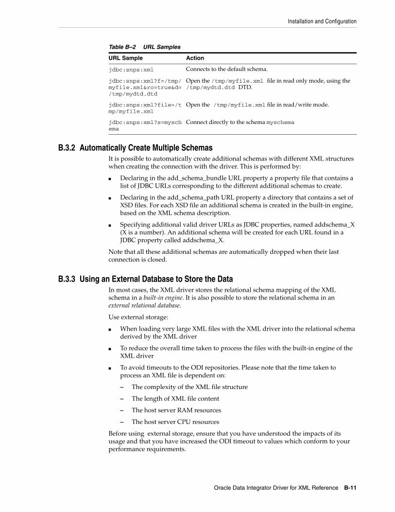
Installation and Configuration
Oracle Data Integrator Driver for XML Reference B-11
B.3.2 Automatically Create Multiple SchemasIt is possible to automatically create additional schemas with different XML structures when creating the connection with the driver. This is performed by:
■ Declaring in the add_schema_bundle URL property a property file that contains a list of JDBC URLs corresponding to the different additional schemas to create.
■ Declaring in the add_schema_path URL property a directory that contains a set of XSD files. For each XSD file an additional schema is created in the built-in engine, based on the XML schema description.
■ Specifying additional valid driver URLs as JDBC properties, named addschema_X (X is a number). An additional schema will be created for each URL found in a JDBC property called addschema_X.
Note that all these additional schemas are automatically dropped when their last connection is closed.
B.3.3 Using an External Database to Store the DataIn most cases, the XML driver stores the relational schema mapping of the XML schema in a built-in engine. It is also possible to store the relational schema in an external relational database.
Use external storage:
■ When loading very large XML files with the XML driver into the relational schema derived by the XML driver
■ To reduce the overall time taken to process the files with the built-in engine of the XML driver
■ To avoid timeouts to the ODI repositories. Please note that the time taken to process an XML file is dependent on:
– The complexity of the XML file structure
– The length of XML file content
– The host server RAM resources
– The host server CPU resources
Before using external storage, ensure that you have understood the impacts of its usage and that you have increased the ODI timeout to values which conform to your performance requirements.
Table B–2 URL Samples
URL Sample Action
jdbc:snps:xml Connects to the default schema.
jdbc:snps:xml?f=/tmp/myfile.xml&ro=true&d=/tmp/mydtd.dtd
Open the /tmp/myfile.xml file in read only mode, using the /tmp/mydtd.dtd DTD.
jdbc:snps:xml?file=/tmp/myfile.xml
Open the /tmp/myfile.xml file in read/write mode.
jdbc:snps:xml?s=myschema
Connect directly to the schema myschema

Installation and Configuration
B-12 Oracle Fusion Middleware Connectivity and Knowledge Modules Guide for Oracle Data Integrator
These schemas are created in addition to the one that may be created with the properties specified in the JDBC driver URL.
The external storage is configured with a set of properties described in Table B–3. These properties can be passed in several ways:
■ Passing the Properties in the Driver URL
■ Setting the Properties in ODI Studio
■ Setting the Properties in a Properties File
Passing the Properties in the Driver URLThe properties can be directly set in the driver URL. When using this method, the properties have to be prefixed with dp_ . For example, if connecting to an Oracle database, specify the Oracle JDBC driver name in the driver parameter as follows:
dp_driver=oracle.jdbc.driver.OracleDriver.
Setting the Properties in ODI StudioThe properties can be specified on the Properties tab of the Data Server editor in Topology Navigator. When using this method, the properties have to be prefixed with dp_. For example, if you want to set the driver parameter:
1. In the Key column, enter dp_driver
2. In the Value column, enter oracle.jdbc.driver.OracleDriver if you are connecting to an Oracle database.
Setting the Properties in a Properties FileThe properties can be set in an external database properties file. This properties file, also called property bundle, is a text file with the .properties extension containing a set of lines with on each line a <property>=<value> pair.
This external database porperties file contains the properties of a JDBC connection to the relational database schema. The properties file is referenced using the db_props property in the JDBC URL.
When using this method, note the following:
■ The properties in the properties file are not prefixed and used as described in Table B–3.
■ The db_props property is set to the name of the properties file including the .properties extension. The db_props property indicates that the schema must be loaded in a database schema whose connection information is stored in a external database properties file.
■ The properties files has to be deployed by the agent using the XML connection. The location the properties file depends on the agent you are using:
Note: Supported RDBMS for external storage include Oracle, Microsoft SQL Server, MySQL, and Hypersonic SQL 2.0. The complete list of technologies that support external storage is available on Oracle Technical Network (OTN) :
http://www.oracle.com/technology/products/oracle-data-integrator/index.html.

Installation and Configuration
Oracle Data Integrator Driver for XML Reference B-13
– Local agent (Studio): Place the external DB properties file in the <user.dir>/odi/oracledi/userlib folder
– Standalone Agent: Place the external DB properties file in oracledi/agent/drivers folder
– JavaEE Agent: The external DB properties file should be packed into a JAR or ZIP file and added to the template generated by the Java EE agent. See "Deploying an Agent in a Java EE Application Server (Oracle WebLogic Server)" in the Developer's Guide for Oracle Data Integrator for more information.
■ The properties file must be set in the classpath of Oracle Data Integrator that uses the XML driver. Typically, you can install it with your custom drivers.
It is possible to set or override the external database properties on the URL. These properties must be prefixed with the string dp_. For example:
jdbc:snps:xml?file=/temp/payload.xml&dp_driver=<external_db_driver>&dp_url=<external_db_url>
The properties for configuring external storage are described in Table B–3.
Note: When connecting to the external database, the XML driver uses JDBC connectivity. Make sure that the JDBC driver to access this external database is also available in the ODI classpath.
Table B–3 Properties of the External Database Properties File
Property Mandatory Type Default Description
driver Yes string - JDBC driver name.
Important: The driver class file must be in the classpath of the java application.
url Yes string - JDBC URL
user Yes string - Login used to connect the database
password Yes string - Encrypted password of the user.
Note: To encrypt the password, use the encode.bat command. See the Installing and Configuring Oracle Data Integrator for more information.
schema Yes string - Database schema storing the relational schema and the XML data.
Note for MS SQLServer that:
■ If schema is not specified, tables will be created under the default schema of the user
■ If schema is specified, tables will be created under this schema
Limitation when using v3 mode: When using an external database, make sure that the provided or calculated schema name exists. The schema driver property value must match the schema property value of the external database. Otherwise an error is raised. "
catalog Yes string - For Microsoft SQL Server only. Database catalog storing the XML data & information.
drop_on_connect or doc
No boolean (true|false)
false Drop the tables from the database schema if they already exist. If set to N the existing tables are preserved.

Installation and Configuration
B-14 Oracle Fusion Middleware Connectivity and Knowledge Modules Guide for Oracle Data Integrator
create_tables or ct
No (Y | N | AUTO)
AUTO Y: create systematically the tables in the schema.
N: never create the tables in the schema
AUTO: Create the tables if they do not exist.
create_indexes or ci
No boolean (true|false)
true Y: create indexes on tables' PK and FK
N: do not create the indexes. This value provides faster INSERT but dramatically slows SELECT in the data. It also saves storage space on your RDB.
numeric_scale or ns
No integer empty Scale of the numeric columns generated during the XML to SQL mapping.
truncate_before_load or tbl
No boolean (true|false)
true true: truncate all data when connecting
false: preserve existing data
ids_in_db or iidb
No boolean (true|false)
true true: preserve identifiers (counters) in the database for a future append connection
false: do not preserve identifiers. Future append is not possible.
drop_tables_on_drop_schema or dtods
No boolean (true|false)
true true: a DROP SCHEMA does not only causes the reference to the database schema to be erased from the driver, but also causes all tables to be dropped.
false: DROP SCHEMA erases the reference to the database schema from the driver, but the tables are kept in the database schema.
use_prepared_statements or ups
No boolean (true|false)
true true: use the prepared statements with the database connection to perform driver operation (load/unload files).
false: do not use the prepare statement.
Processing is usually faster with prepare statement. The database and driver must support prepared statements in order to use this option.
use_batch_update or ubu
No boolean (true|false)
true true: use batch update with the database connection.
false: do not use batch update.
Inserting data is usually faster with batch update. Should be set to Yes only if the following conditions are met:
■ The database and driver support batch update
■ The database supports prepared statements
■ The use_prepared_statements parameter is set toYes
Note: The batch update options specified here are only used to load the data in the schema. To use batch update when manipulating data in the schema, you must specify batch update options in your Java application.
batch_update_size or bus
No integer 30 Batch update size. Records will be written in the database schema by batches of this size, if the use_batch_update property is set to true.
Table B–3 (Cont.) Properties of the External Database Properties File
Property Mandatory Type Default Description

Installation and Configuration
Oracle Data Integrator Driver for XML Reference B-15
The following sample is an example of a property file for using an Oracle Database as the external storage:
driver=oracle.jdbc.driver.OracleDriverurl=jdbc:oracle:thin:@HOST:PORT:SIDuser=USER_NAMEpassword=ENCODED_PASSWORDschema=USER_NAMEdrop_on_connect=Ycreate_tables=AUTOcreate_indexes=Y
commit_periodically or cp
No boolean (true|false)
true A COMMIT will be sent regularly when loading data from the XML file into the database schema. This regular COMMIT avoids overloading of the database log when loading large XML data files.
Should be set to true only if the following conditions are met:
■ The database supports batch update
■ The database supports prepared statements
■ The use_prepared_statements parameter is set to true
■ The use_batch_updates parameters is set to true
Note: The commit options specified here are only used to load the data in the schema. To commit when performing transactions in the schema, you must specify the commit in your Java application.
num_inserts_before_commit or nibc
No integer 1000 Interval in records between each COMMIT, if the commit_periodically property is set to true.
reserve_chars_for_column or rcfc
No integer 3 Long XML names are truncated to fit the maximum allowed size on the RDBMS, according to the maximum allowed size for column names returned by the JDBC driver.
However, there are some situations when you will want to reserve characters to make the driver-generated names shorter. The number of reserved character is defined in the reserve_chars_for_column value.
For example, on a database with a maximum of 30 characters and with this property set to 3 (which is the default), all column names will not be larger than 27 characters.
reserve_chars_for_table or rcft
No integer 3 Same as reserve_chars_for_column (rcfc) property but applies to names of the table created in the RDBMS schema.
varchar_length or vl
No integer 255 Size of all the columns of the relational structure that will be used to contain string data.
numeric_length or nl
No integer 10 Size of all the columns of the relational structure that will be used to contain numeric data.
unicode No boolean (true|false)
For MS SQL Server:
If unicode = true, nvarchar is used.
If unicode = false or not set, varchar is used.
Table B–3 (Cont.) Properties of the External Database Properties File
Property Mandatory Type Default Description

Detailed Driver Commands
B-16 Oracle Fusion Middleware Connectivity and Knowledge Modules Guide for Oracle Data Integrator
truncate_before_load=Yids_in_db=Ydrop_tables_on_drop_schema=Yuse_prepared_statements=Yuse_batch_update=Ybatch_update_size=30commit_periodically=Ynum_inserts_before_commit=1000reserve_chars_for_column=3reserve_chars_for_table=3
The following sample is an example of a property file for using a Microsoft SQL Server database as the external storage:
driver=com.microsoft.jdbc.sqlserver.SQLServerDriverurl=jdbc:microsoft:sqlserver://SERVER_NAME:PORT;SelectMethod=cursoruser=USER_NAMEpassword=ENCODED_PASSWORDschema=OWNNER_NAMEdrop_on_connect=Ycreate_tables=AUTOcreate_indexes=Ytruncate_before_load=Yids_in_db=Ydrop_tables_on_drop_schema=Yuse_prepared_statements=Yuse_batch_update=Ybatch_update_size=30commit_periodically=Ynum_inserts_before_commit=1000reserve_chars_for_column=3reserve_chars_for_table=3
B.4 Detailed Driver CommandsThe following statements are specific to the XML driver, and allow to manage XML files and schemas. They can be launched as standard SQL statements on the JDBC connection to the XML driver.
To manipulate the data stored in the schemas, you may use standard SQL syntax. This syntax is either the built-in engine's SQL Syntax, or the SQL Syntax of the External Database engine you use.
ConventionsThe following conventions are used within this document:
■ [ A ] means A is optional
■ [ A | B ] means A or B but the parameter is optional.
■ { B | C } means B or C must be used.
■ [A] [B] means a set of arguments that are not ordered.
■ ( and ) are the characters '(' and ')'.
■ keywords are in UPPERCASE
This section details the following driver specific commands:
■ CREATE FILE

Detailed Driver Commands
Oracle Data Integrator Driver for XML Reference B-17
■ CREATE FOREIGNKEYS
■ CREATE XMLFILE
■ CREATE SCHEMA
■ DROP FOREIGNKEYS
■ DROP SCHEMA
■ LOAD FILE
■ SET SCHEMA
■ SYNCHRONIZE
■ UNLOCK FILE
■ TRUNCATE SCHEMA
■ VALIDATE
■ WRITE MAPPING FILE
■ COMMIT
■ CREATE TABLE
■ DELETE
■ DISCONNECT
■ DROP TABLE
■ INSERT INTO
■ ROLLBACK
■ SELECT
■ SET AUTOCOMMIT
■ UPDATE
B.4.1 CREATE FILEGenerate an XML file called <file_name> from the current schema data, or from a specific schema.
If the EMPTY option is specified, an empty file with the XML structure specified in the DTD or XSD is generated.
CREATE [EMPTY] FILE <file_name> [FROM SCHEMA <schema_name>] [JAVA_ENCODING <java_encoding> XML_ENCODING <xml_encoding>] [NO_CLOSING_TAGS] [NO_DEFAULT_NS]
Parameters
FROM SCHEMASpecify the schema in which data will be written in the XML file.
JAVA_ENCODINGEncoding of the generated File.
XML_ENCODINGEncoding generated in the file's xml tag.

Detailed Driver Commands
B-18 Oracle Fusion Middleware Connectivity and Knowledge Modules Guide for Oracle Data Integrator
Example of generated tag: <?xml version="1.0" encoding="ISO-8859-1"?>
Note that Java and XML encoding should always be specified together.
NO_CLOSING_TAGIf this parameter is specified, the driver generates the empty tags with closing tag. By default, the driver generates an empty element as <element></element>. with the no_closing_tags parameter, it generates <element/>.
NO_DEFAULT_NSIf this parameter is specified, the driver generates the target file without a default namespace entry.
Remarks■ If the file name contains spaces, enclose it in double quotes
■ The encoding values should be enclosed in double quotes as they may contain special characters.
B.4.2 CREATE FOREIGNKEYSCreate physically all the foreign keys joining the tables from the relational schema in the database. This command is helpful to enforce integrity constraints on the schema.
CREATE FOREIGNKEYS
RemarksAfter using CREATE FOREIGNKEYS, it is not possible any longer to perform a LOAD FILE.
B.4.3 CREATE XMLFILEGenerate an XML file called <file_name> from the default schema data, or from a specific schema.
CREATE XMLFILE <file_name> [FROM SCHEMA <schema_name>] [JAVA_ENCODING <java_encoding> XML_ENCODING <xml_encoding>] [NO_CLOSING_TAGS][NO_DEFAULT_NS]
Parameters
FROM SCHEMASpecify the schema in which data will be written in the XML file.
JAVA_ENCODINGEncoding of the generated File.
XML_ENCODINGEncoding generated in the file's xml tag. Example of generated tag: <?xml version="1.0" encoding="ISO-8859-1"?>.
Note: When requested, the driver always returns "virtual" foreign keys, corresponding to the relational structure mapping. It does not return the real foreign keys enforced at database level.
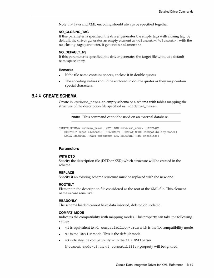
Detailed Driver Commands
Oracle Data Integrator Driver for XML Reference B-19
Note that Java and XML encoding should always be specified together.
NO_CLOSING_TAGIf this parameter is specified, the driver generates the empty tags with closing tag. By default, the driver generates an empty element as <element></element>. with the no_closing_tags parameter, it generates <element/>.
NO_DEFAULT_NSIf this parameter is specified, the driver generates the target file without a default namespace entry.
Remarks■ If the file name contains spaces, enclose it in double quotes
■ The encoding values should be enclosed in double quotes as they may contain special characters.
B.4.4 CREATE SCHEMACreate in <schema_name> an empty schema or a schema with tables mapping the structure of the description file specified as <dtd/xsd_name>.
CREATE SCHEMA <schema_name> [WITH DTD <dtd/xsd_name>] [REPLACE] [ROOTELT <root element>] [READONLY] [COMPAT_MODE <compatibility mode>] [JAVA_ENCODING <java_encoding> XML_ENCODING <xml_encoding>]
Parameters
WITH DTDSpecify the description file (DTD or XSD) which structure will be created in the schema.
REPLACESpecify if an existing schema structure must be replaced with the new one.
ROOTELTElement in the description file considered as the root of the XML file. This element name is case sensitive.
READONLYThe schema loaded cannot have data inserted, deleted or updated.
COMPAT_MODEIndicates the compatibility with mapping modes. This property can take the following values:
■ v1 is equivalent to v1_compatibility=true wich is the 1.x compatibility mode
■ v2 is the 10g/11g mode. This is the default mode.
■ v3 indicates the compatibility with the XDK XSD parser
If compat_mode=v3, the v1_compatibility property will be ignored.
Note: This command cannot be used on an external database.

Detailed Driver Commands
B-20 Oracle Fusion Middleware Connectivity and Knowledge Modules Guide for Oracle Data Integrator
JAVA_ENCODINGEncoding of the target XML file(s) generated from schema.
Note: Java and XML encoding should always be specified together.
XML_ENCODINGEncoding generated in the target files' XML tag. Example of generated tag: <?xml version="1.0" encoding="ISO-8859-1"?>.
Remarks■ The XML file data is not loaded. This command is similar to LOAD FILE but does
not load the XML file data.
■ The schema is created in READONLY mode since no XML file is associated with it.
■ The connection schema does not automatically switch to the newly created schema.
■ If the file name contains spaces, enclose the name id double quotes.
■ The encoding values should be enclosed in double quotes as they may contain special characters.
B.4.5 DROP FOREIGNKEYSDrop all the foreign keys on the tables of the relational schema in the database. This command is helpful to drop all integrity constraints on the schema.
DROP FOREIGNKEYS
B.4.6 DROP SCHEMADrop an existing schema. If <schema_name> is not specified, the current schema is dropped. It is not possible to drop a schema if there are pending connections to this schema. Trying to drop a schema with existing connections causes an exception.
DROP SCHEMA [<schema_name>]
B.4.7 LOAD FILELoad the <file_name> XML file into the current relational schema.
LOAD FILE <file_name> [WITH DTD <dtd/xsd_name> | INSERT_ONLY] [ON SCHEMA <schema_name>] [REPLACE] [READONLY] [ROOTELT <root element>] [AUTO_UNLOCK] [DB_PROPS <external database properties>]
Note: When using the SYNCHRONIZE command, only those DB schemas that have been created with 'v3' option will parse the DTD/XSD in the 'v3' mode. In 'v3' mode all the restrictions on schema name value corresponding with DB property for schema name etc. will apply.

Detailed Driver Commands
Oracle Data Integrator Driver for XML Reference B-21
Parameters
WITH DTDSpecify the description file (DTD or XSD) which structure will be created in the schema.
INSERT_ONLYAdds the data from the XML file in the schema if it already exists. The new XML file should have valid description file for the existing schema.
ON SCHEMAForce the file to be loaded in <schema_name>. Note that the current schema is not set after the command automatically to <schema_name>.
REPLACESpecify if an existing schema structure with the same name must be replaced with the one that is being loaded.
READONLYThe schema loaded cannot have data inserted, deleted or updated.
ROOTELTElement in the description file considered as the root of the XML file. This element name is case sensitive.
AUTO_UNLOCKIf the XML file is already locked by another driver instance, an exception occurs unless the AUTO_UNLOCK is specified. This parameter unlocks automatically the file if it is locked.
DB_PROPSLoads the file in the external database identified by the properties file called <external database properties>.properties.
Remarks■ If the file name contains spaces, enclose the name in double quotes.
■ When no schema is specified, the driver automatically generates a schema name from the file name.
■ The connection schema does not automatically switch to the loaded schema.
■ If the XML file is already open in another schema, an exception occurs.
B.4.8 SET SCHEMASet the current schema to <schema_name>.
SET SCHEMA <schema_name>
RemarksIt is necessary to specify a name for the schema.
B.4.9 SYNCHRONIZESynchronize data in the schema with the file data.
SYNCHRONIZE [ALL | SCHEMA <schema_name>] [FROM FILE/FROM DATABASE]

Detailed Driver Commands
B-22 Oracle Fusion Middleware Connectivity and Knowledge Modules Guide for Oracle Data Integrator
[IGNORE CONFLICTS]
Parameters
ALLSynchronizes all schemas
SCHEMASynchronizes only <schema_name>
FROM FILEForces the data to be loaded from the file to the schema. Erases all changes in the schema.
FROM DATABASEForces the data to be loaded from the schema to the file. Erases all changes in the file.
IGNORE CONFLICTSIf FROM FILE/DATABASE are not specified, the driver automatically determines where data have been modified (in the FILE or DATABASE) and updates the unmodified data. If both the FILE and the DATABASE have been modified, the driver issues a Conflict Error. if the IGNORE CONFLICTS parameter is used, no error is issued, and if performing a SYNCHRONIZE ALL, the following schemas will be synchronized.
B.4.10 UNLOCK FILEUnlocks <file_name> if it is locked by another instance of the driver.
UNLOCK FILE <file_name>
B.4.11 TRUNCATE SCHEMAClears all data from the current schema, or from <schema_name>.
TRUNCATE SCHEMA [<schema_name>]
B.4.12 VALIDATEVerifies that the XML file <file_name> is well-formed and validates the content of the XML file <file_name> against the XML Schema (XSD) if the schema is referenced in the XML file. This command returns an exception if the file is not valid. For a full description of the validation performed, see:
http://xerces.apache.org/xerces2-j/features.html#validation.schema
VALIDATE [FILE <file_name>] [ERROR_ON_WARNING|IGNORE_ON_WARNING] [ERROR_ON_ERROR|IGNORE_ON_ERROR] [ERROR_ON_FATAL_ERROR|IGNORE_ON_FATAL_ERROR] [VERBOSE]
Note: A schema is marked updated only when a data modification (update, delete, insert, drop) is executed in a connection to that schema. It is not marked as updated, when the order is launched from a connection to another schema.

Detailed Driver Commands
Oracle Data Integrator Driver for XML Reference B-23
Parameters
FILE <file_name>Name of the XML file to validate.
ERROR_ON_WARNING | IGNORE_ON_WARNINGIgnore or generate errors on XSD validation warnings, such as values out of range. The default value is IGNORE_ON_WARNING.
ERROR_ON_ERROR | IGNORE_ON_ERRORIgnore or generate errors on XSD validation errors, such as non conform attribute or element. The default value is ERROR_ON_ERROR.
ERROR_ON_FATAL_ERROR | IGNORE_ON_FATAL_ERRORIgnore or generate errors on XSD validation fatal errors, such as malformed XML. The default value is ERROR_ON_FATAL_ERROR.
VERBOSEDisplays on the Java console the detailed errors and number of the line causing the error. Nothing is displayed by default on the console.
B.4.13 WRITE MAPPING FILEWrites out the element/attribute name to table/table.column name mapping for each element/attribute to the specified file. The mapping file helps to understand the relational structure that has been created for the XSD/DTD file. This command can be used only when the schema was created in v3 mode. Otherwise exception is thrown.
WRITEMAPPINGFILE <file-path> [FROM SCHEMA <schema-name>] [JAVA_ENCODING <java_encoding> XML_ENCODING <xml-encoding>]
Parameters
file_pathName of the generated mapping file
FROM_SCHEMAIf the optional FROM SCHEMA parameter is not provided, the current schema will be used.
JAVA_ENCODINGEncoding of the generated file, for example: ISO8859_1. You will find a list of supported encoding at the following URL: http://download.oracle.com/javase/6/docs/technotes/guides/intl/encoding.doc.html.
Note that if the Java encoding is specified, the XML encoding should also be specified.
XML_ENCODINGEncoding in the xml tag of the generated file.
Example of generated tag: <?xml version="1.0" encoding="ISO-8859-1"?>
You will find a list of supported encoding at the following URL: http://download.oracle.com/javase/6/docs/technotes/guides/intl/encoding.doc.html.

SQL Syntax
B-24 Oracle Fusion Middleware Connectivity and Knowledge Modules Guide for Oracle Data Integrator
Note that if the XML encoding is specified, the Java encoding should also be specified.
Example B–1 Mapping File
<?xml version = '1.0' encoding = 'UTF-8'?><personnel xmlns:x2r="http://www.oracle.com/odi/xml-mapping" x2r:tableName="PERSONNEL"> <person x2r:tableName="PERSON" id="ID" select="SELECT_"> <email x2r:tableName="EMAIL"></email> <link x2r:tableName="LINK" manager="MANAGER" subordinates="SUBORDINATES"></link> <name x2r:tableName="NAME"> <given x2r:columnName="GIVEN"></given> <family x2r:columnName="FAMILY"></family> </name> <url x2r:tableName="URL" href="HREF"></url> </person></personnel>
B.5 SQL SyntaxThe following statements are available when using the built-in engine to store the XML schema. They enable the management of the data and data structure in the schema through Standard SQL Syntax.
This section contains the following topics:
■ SQL Statements
■ SQL FUNCTIONS
B.5.1 SQL StatementsAny number of commands may be combined. You can optionally use the semicolon character (;) to separate each command.
This section details the following commands:
■ COMMIT
■ CREATE TABLE
■ DELETE
■ DISCONNECT
■ DROP TABLE
■ INSERT INTO
■ ROLLBACK
■ SELECT
■ SET AUTOCOMMIT
■ UPDATE
■ Expressions, Condition and Values
Note: If you are using an external database, you may use the database engine querying syntax instead of this one.

SQL Syntax
Oracle Data Integrator Driver for XML Reference B-25
B.5.1.1 COMMITEnds a transaction on the schema and makes the changes permanent.
COMMIT [WORK]
B.5.1.2 CREATE TABLECreate a tables and its constraints in the relational schema.
CREATE TABLE <table_name> ( <columnDefinition> [, ...] [, <constraintDefinition>...])
<columnDefinition> ::= <column_name> <datatype> [(anything)] [[NOT] NULL] [IDENTITY] [PRIMARY KEY]
<constraintDefinition> ::=[ CONSTRAINT <constraint_name> ] UNIQUE ( <column_name> [,<column>...] ) | PRIMARY KEY ( <column_name> [,<column_name>...] ) | FOREIGN KEY ( <column_name> [,<column_name>...] ) REFERENCES <referenced_table> ( <column_name> [,<column_name>...] )
Remarks■ IDENTITY columns are automatically incremented integer columns. The last
inserted value into an identity column for a connection is available using the IDENTITY() function.
■ Valid datatypes are: BIT, TINYINT, BIGINT, LONGVARBINARY, VARBINARY, BINARY, LONGVARCHAR, CHAR, NUMERIC, DECIMAL, INTEGER, SMALLINT, FLOAT, REAL, DOUBLE, VARCHAR, DATE, TIME, TIMESTAMP, OBJECT
B.5.1.3 DELETERemove rows in a table in the relational schema. This function uses a standard SQL Syntax.
DELETE FROM <table_name> [ WHERE <expression> ]
B.5.1.4 DISCONNECTCloses this connection.
DISCONNECT
Remarks■ It is not required to call this command when using the JDBC interface: it is called
automatically when the connection is closed.
■ After disconnecting, it is not possible to execute other queries with this connection.
B.5.1.5 DROP TABLERemove a table, the data and indexes from the relational schema.
DROP TABLE <table_name>

SQL Syntax
B-26 Oracle Fusion Middleware Connectivity and Knowledge Modules Guide for Oracle Data Integrator
B.5.1.6 INSERT INTOInsert one or more new rows of data into a table.
INSERT INTO <table_name> [ ( <column_name> [,...] ) ] { VALUES (<expression> [,...]) | <SELECT Statement> }
B.5.1.7 ROLLBACKUndo the changes made since the last COMMIT or ROLLBACK.
ROLLBACK
B.5.1.8 SELECTRetrieves information from one or more tables in the schema.
SELECT [DISTINCT] { <select_expression> | <table_name>.* | * } [, ... ][ INTO <new_table> ] FROM <table_list>[ WHERE <expression> ][ GROUP BY <expression> [, ...] ][ ORDER BY <order_expression> [, ...] ][ { UNION [ALL] | {MINUS|EXCEPT} | INTERSECT } <select_statement> ]
<table_list> ::= <table_name> [ { INNER | LEFT [OUTER] } JOIN <table_name> ON <expression> ] [, ...]
<select_expression> ::= { <expression> | COUNT(*) | {COUNT | MIN | MAX | SUM | AVG} (<expression>) <column_alias>}
<order_expression> ::= { <column_number> | <column_alias> | <select_expression> } [ ASC | DESC ]
B.5.1.9 SET AUTOCOMMITSwitches on or off the connection's auto-commit mode. If switched on, then all statements will be committed as individual transactions. Otherwise, the statements are grouped into transactions that are terminated by either COMMIT or ROLLBACK. By default, new connections are in auto-commit mode.
SET AUTOCOMMIT { TRUE | FALSE }
B.5.1.10 UPDATEModifies data of a table in the database.
UPDATE table SET column = <expression> [, ...] [WHERE <expression>]
B.5.1.11 Expressions, Condition and Values<expression> ::= [NOT] <condition> [ { OR | AND } <condition> ]
<condition> ::= { <value> [ || <value> ] | <value> { = | < | <= | > | >= | <> | != | IS [NOT] } <value> | EXISTS(<select_statement>)

SQL Syntax
Oracle Data Integrator Driver for XML Reference B-27
| <value> BETWEEN <value> AND <value> | <value> [NOT] IN ( {<value> [, ...] | selectStatement } ) | <value> [NOT] LIKE <value> [ESCAPE] value }
<value> ::= [ + | - ] { term [ { + | - | * | / } term ] | ( condition ) | function ( [parameter] [,...] ) | selectStatement_giving_one_value
<term> ::= { 'string' | number | floatingpoint | [table.]column | TRUE | FALSE | NULL }
<string> ::=■ Starts and ends with a single '. In a string started with ' use '' to create a '.
■ LIKE uses '%' to match any (including 0) number of characters, and '_' to match exactly one character. To search for '%' itself, '\%' must be used, for '_' use '\_'; or any other escaping character may be set using the ESCAPE clause.
<name> ::=■ A name starts with a letter and is followed by any number of letters or digits.
Lowercase is changed to uppercase except for strings and quoted identifiers. Names are not case-sensitive.
■ Quoted identifiers can be used as names (for example for tables or columns). Quoted identifiers start and end with ". In a quoted identifier use "" to create a ". With quoted identifiers it is possible to create mixed case table and column names. Example: CREATE TABLE "Address" ("Nr" INTEGER, "Name" VARCHAR); SELECT * FROM "Address". Quoted identifiers are not strings.
<values> ::=■ A 'date' value starts and ends with ', the format is yyyy-mm-dd (see java.sql.Date).
■ A 'time' value starts and ends with ', the format is hh:mm:ss (see java.sql.Time).
■ Binary data starts and ends with ', the format is hexadecimal. '0004ff' for example is 3 bytes, first 0, second 4 and last 255 (0xff).
B.5.2 SQL FUNCTIONSTable B–4 lists the numerical functions.
Table B–4 Numerical Functions
Function Description
ABS(d) returns the absolute value of a double value
ACOS(d) returns the arc cosine of an angle
ASIN(d) returns the arc sine of an angle
ATAN(d) returns the arc tangent of an angle
ATAN2(a,b) returns the tangent of a/b
CEILING(d) returns the smallest integer that is not less than d
COS(d) returns the cosine of an angle
COT(d) returns the cotangent of an angle
DEGREES(d) converts radians to degrees
EXP(d) returns e (2.718...) raised to the power of d

SQL Syntax
B-28 Oracle Fusion Middleware Connectivity and Knowledge Modules Guide for Oracle Data Integrator
Table B–5 lists the string functions.
FLOOR(d) returns the largest integer that is not greater than d
LOG(d) returns the natural logarithm (base e)
LOG10(d) returns the logarithm (base 10)
MOD(a,b) returns a modulo b
PI() returns pi (3.1415...)
POWER(a,b) returns a raised to the power of b
RADIANS(d) converts degrees to radians
RAND() returns a random number x bigger or equal to 0.0 and smaller than 1.0
ROUND(a,b) rounds a to b digits after the decimal point
SIGN(d) returns -1 if d is smaller than 0, 0 if d==0 and 1 if d is bigger than 0
SIN(d) returns the sine of an angle
SQRT(d) returns the square root
TAN(d) returns the trigonometric tangent of an angle
TRUNCATE(a,b) truncates a to b digits after the decimal point
BITAND(a,b) return a & b
BITOR(a,b) returns a | b
Table B–5 String Functions
Function Description
ASCII(s) returns the ASCII code of the leftmost character of s
CHAR(c) returns a character that has the ASCII code c
CONCAT(str1,str2) returns str1 + str2
DIFFERENCE(s1,s2) returns the difference between the sound of s1 and s2
INSERT(s,start,len,s2) returns a string where len number of characters beginning at start has been replaced by s2
LCASE(s) converts s to lower case
LEFT(s,count) returns the leftmost count of characters of s
LENGTH(s) returns the number of characters in s
LOCATE(search,s,[start]) returns the first index (1=left, 0=not found) where search is found in s, starting at start
LTRIM(s) removes all leading blanks in s
REPEAT(s,count) returns s repeated count times
REPLACE(s,replace,s2) replaces all occurrences of replace in s with s2
RIGHT(s,count) returns the rightmost count of characters of s
RTRIM(s) removes all trailing blanks
Table B–4 (Cont.) Numerical Functions
Function Description

SQL Syntax
Oracle Data Integrator Driver for XML Reference B-29
Table B–6 lists the date/time functions.
Note that a date value starts and ends with a single quote ('), the format is yyyy-mm-dd (see java.sql.Date). A time value starts and ends with a single quote ('), the format is hh:mm:ss (see java.sql.Time).
Table B–7 lists the system functions.
SOUNDEX(s) returns a four character code representing the sound of s
SPACE(count) returns a string consisting of count spaces
SUBSTRING(s,start[,len]) returns the substring starting at start (1=left) with length len
UCASE(s) converts s to upper case
LOWER(s) converts s to lower case
UPPER(s) converts s to upper case
Table B–6 Date/Time Functions
Function Description
CURDATE() returns the current date
CURTIME() returns the current time
DAYNAME(date) returns the name of the day
DAYOFMONTH(date) returns the day of the month (1-31)
DAYOFWEEK(date) returns the day of the week (1 means Sunday)
DAYOFYEAR(date) returns the day of the year (1-366)
HOUR(time) return the hour (0-23)
MINUTE(time) returns the minute (0-59)
MONTH(date) returns the month (1-12)
MONTHNAME(date) returns the name of the month
NOW() returns the current date and time as a timestamp
QUARTER(date) returns the quarter (1-4)
SECOND(time) returns the second (0-59)
WEEK(date) returns the week of this year (1-53)
YEAR(date) returns the year
Table B–7 System Functions
Function Description
IFNULL(exp,value) if exp is null, value is returned else exp
CASEWHEN(exp,v2,v2) if exp is true, v1 is returned, else v2
CONVERT(term,type) converts exp to another data type
CAST(term AS type) converts exp to another data type
Table B–5 (Cont.) String Functions
Function Description

JDBC API Implemented Features
B-30 Oracle Fusion Middleware Connectivity and Knowledge Modules Guide for Oracle Data Integrator
B.6 JDBC API Implemented FeaturesTable B–8 lists the JDBC API features that are implemented in the Oracle Data Integrator Driver for XML:
Table B–9 lists JDBC Java classes.
Table B–8 JDBC API Features
Feature Groups JDBC Version Support
Batch Update 2.0 Core Yes
Blob/Clob 2.0 Core Yes
JNDI DataSources 2.0 Optional Yes
Failover support - Yes
Transaction SavePoints 3.0 Yes
Unicode support - No
Distributed Transaction 2.0 Optional No
Connection Pooling 2.0 Optional No
Cluster support - No
Table B–9 JDBC Java Classes
JDBC Class JDBC Version Support
Array 2.0 Core No
Blob 2.0 Core Yes
CallableStatement 1.0 Yes
Clob 2.0 Core Yes
Connection 1.0 Yes
ConnectionPoolDataSource 2.0 Optional No
DatabaseMetaData 1.0 Yes
DataSource 2.0 Optional No
Driver 1.0 Yes
Ref 2.0 Core No
ResultSet 1.0 Yes
ResultSetMetaData 1.0 Yes
RowSet 2.0 Optional No
Statement 1.0 Yes
Struct 2.0 Core No
PreparedStatement 1.0 Yes
XAConnection 2.0 Optional No
XADataSource 2.0 Optional No

XML Schema Supported Features
Oracle Data Integrator Driver for XML Reference B-31
B.7 XML Schema Supported FeaturesThe driver supports part of the XML Schema (XSD) specification. Supported elements are listed in this section.
For more information on the XML Schema specification, see the W3C specification at http://www.w3.org/TR/xmlschema-1/.
This section contains the following topics:
■ Datatypes
■ Supported Elements
■ Unsupported Features
B.7.1 DatatypesThe following datatypes are supported:
■ These datatypes are converted to String columns: string, normalizedString, token, nmtoken, nmtokens, anyUri, id, idref, date, datetime, time, hexBinary
■ These datatypes are converted to Integer columns: int, positiveInteger, negativeInteger, nonNegativeInteger, onPositiveInteger, long, unsignedLong, unsignedInt, short, unsignedShort, byte, unsignedByte, boolean (Boolean are converted to a numeric column with 0 or 1, but they can take "true" or "false" values from the input files)
■ These datatypes are converted to Decimal (with 2 decimal places) columns: decimal, float, double
B.7.2 Supported ElementsThis section lists all schema elements. Supported syntax elements are shown in bold. Unsupported syntax elements are shown in regular font. They are ignored by the driver.
This section details the following schema elements:
■ All
■ Attribute
■ AttributeGroup
■ Choice
■ ComplexContent
■ ComplexType
■ Element
■ Extension
■ Group
■ Import
■ Include
■ List
■ Restriction
■ Schema

XML Schema Supported Features
B-32 Oracle Fusion Middleware Connectivity and Knowledge Modules Guide for Oracle Data Integrator
■ Sequence
■ SimpleContent
■ SimpleType
B.7.2.1 AllThis element specifies that child elements can appear in any order and that each child element can occur zero or one time.
Note that child elements mandatory properties (minOccurs=1) are not managed by the driver. This should be handled by checks on the data, and by validating the XML contents against the XSD.
<all id=ID maxOccurs=1 minOccurs=0|1 any attributes>(annotation?,element*)</all>
B.7.2.2 AttributeThis element defines an attribute.
<attribute default=string id=ID name=NCName type=QName use=optional|prohibited|required ref=QName fixed=string form=qualified|unqualified any attributes>(annotation?,(simpleType?))</attribute>
Note that the use attribute of this element defines the column mapped by the driver for the attribute as mandatory or not.
B.7.2.3 AttributeGroupThis element defines a set of attributes.
<attributeGroup id=ID name=NCName ref=QName any attributes>(annotation?),((attribute|attributeGroup)*,anyAttribute?))</attributeGroup>
Note: XML files generated or updated using the XML driver should ideally be validated against their corresponding XSD files using the VALIDATE command after generation.

XML Schema Supported Features
Oracle Data Integrator Driver for XML Reference B-33
B.7.2.4 ChoiceThis element allows one and only of the elements to be present within the containing element.
<choice id=ID maxOccurs=nonNegativeInteger|unbounded minOccurs=nonNegativeInteger any attributes>(annotation?,(element|group|choice|sequence|any)*)</choice>Note that the child element's unique nature are not managed by the driver. This should be handled by checks on the data, and by validating the XML contents against the XSD.
B.7.2.5 ComplexContentThis element defines extensions or restrictions on a complex type.
<complexContent id=ID mixed=true|false any attributes>(annotation?,(restriction|extension))</complexContent>
B.7.2.6 ComplexTypeThis element defines a complex type.
<complexType name=NCName id=ID abstract=true|false mixed=true|false block=(#all|list of (extension|restriction)) final=(#all|list of (extension|restriction)) any attributes>(annotation?,(simpleContent|complexContent|((group|all|choice|sequence)?,((attribute|attributeGroup)*,anyAttribute?))))</complexType>
B.7.2.7 ElementThis element defines an element of the XML file.
<element name=NCName maxOccurs=nonNegativeInteger|unbounded minOccurs=nonNegativeInteger type=QName id=ID ref=QName substitutionGroup=QName default=string fixed=string form=qualified|unqualified nillable=true|false abstract=true|false

XML Schema Supported Features
B-34 Oracle Fusion Middleware Connectivity and Knowledge Modules Guide for Oracle Data Integrator
block=(#all|list of (extension|restriction)) final=(#all|list of (extension|restriction)) any attributes>annotation?,((simpleType|complexType)?,(unique|key|keyref)*))</element>
B.7.2.8 ExtensionThis element extends an existing simpleType or complexType element
<extension id=ID base=QName any attributes>(annotation?,((group|all|choice|sequence)?,((attribute|attributeGroup)*,anyAttribute?)))</extension>
B.7.2.9 GroupThe group element is used to define a group of elements to be used in complex type definitions.
<group id=ID name=NCName ref=QName maxOccurs=nonNegativeInteger|unbounded minOccurs=nonNegativeInteger any attributes>(annotation?,(all|choice|sequence)?)</group>
Note: The maxOccurs and minOccurs attributes of the element are used in the XML-to-SQL mapping. If a child element is of a simple type and is monovalued (one occurrence only), then this element is mapped to a simple column in the table corresponding to its parent element. Otherwise, a table linked to the parent element's table is created.
Note that if no reference to either minOccurs or maxOccurs is mentioned in an element then the element is consider as monovalued and is transformed to a column. This behavior can be changed using the useImplicitMaxValue URL property. When this property is set to yes, an elements for which maxOccurs is not specified in the XSD is considered as multivalued (maxOccurs ="unbounded").
Note: Using different sub-elements with the same name but with different types is not supported by XML driver. An XSD with such a structure will not be processed correctly.

XML Schema Supported Features
Oracle Data Integrator Driver for XML Reference B-35
B.7.2.10 ImportThis element is used to add multiple schemas with different target namespace to a document.
<import id=ID namespace=anyURI schemaLocation=anyURI any attributes>(annotation?)</import>
B.7.2.11 IncludeThis element is used to add multiple schemas with the same target namespace to a document.
<include id=ID schemaLocation=anyURI any attributes>(annotation?)</include>
B.7.2.12 ListThis element defines a simple type element as a list of values of a specified data type.
<list id=ID itemType=QName any attributes>(annotation?,(simpleType?))</list>
B.7.2.13 RestrictionThis element defines restrictions on a simpleType, simpleContent, or a complexContent.
<restriction id=ID base=QName any attributes>Content for simpleType:(annotation?,(simpleType?,(minExclusive|minInclusive|maxExclusive|maxInclusive|totalDigits|fractionDigits|length|minLength|maxLength|enumeration|whiteSpace|pattern)*))Content for simpleContent:(annotation?,(simpleType?,(minExclusive|minInclusive|maxExclusive|maxInclusive|totalDigits|fractionDigits|length|minLength|maxLength|enumeration|whiteSpace|pattern)*)?, ((attribute|attributeGroup)*,anyAttribute?))Content for complexContent:(annotation?,(group|all|choice|sequence)?, ((attribute|attributeGroup)*,anyAttribute?))</restriction>

XML Schema Supported Features
B-36 Oracle Fusion Middleware Connectivity and Knowledge Modules Guide for Oracle Data Integrator
B.7.2.14 SchemaThis element defines the root element of a schema.
<schema id=ID attributeFormDefault=qualified|unqualified elementFormDefault=qualified|unqualified blockDefault=(#all|list of (extension|restriction|substitution)) finalDefault=(#all|list of (extension|restriction|list|union)) targetNamespace=anyURI version=token xmlns=anyURI any attributes>((include|import|redefine|annotation)*,(((simpleType|complexType|group|attributeGroup)|element|attribute|notation),annotation*)*)</schema>
B.7.2.15 SequenceThis element specifies that the child elements must appear in a sequence. Each child element can occur 0 or more times.
<sequence id=ID maxOccurs=nonNegativeInteger|unbounded minOccurs=nonNegativeInteger any attributes>(annotation?,(element|group|choice|sequence|any)*)</sequence>
Note the following:
■ The Sequence order is not managed by the driver. The sequence order should be handled by loading the xxx_ORDER column generated by the driver.
■ The maxOccurs and minOccurs attributes are not managed by the driver. This should be handled by checks on the data, and by validating the XML contents against the XSD.
B.7.2.16 SimpleContentThis element contains extensions or restrictions on a text-only complex type or on a simple type as content.
<simpleContent id=ID any attributes>(annotation?,(restriction|extension))</simpleContent>
B.7.2.17 SimpleTypeThis element defines a simple type element.
<simpleType name=NCName id=ID any attributes>

XML Schema Supported Features
Oracle Data Integrator Driver for XML Reference B-37
(annotation?,(restriction|list|union))</simpleType>
B.7.3 Unsupported FeaturesThe following elements and features are not supported or implemented by the XML driver.
B.7.3.1 Unsupported ElementsThe following schema elements are not supported by the XML driver.
■ Any/anyAttribute: The any and anyAttribute elements enables you to extend the XML document with any element or attribute, even if it is not specified by the schema. These elements are not supported.
■ Key/keyRef/Unique: These elements allow the definition of constraints in the schema. These elements and their child elements (selector, field) are ignored.
■ Redefine: The redefine element redefines simple and complex types, groups, and attribute groups from an external schema. This element is not supported.
■ anyType: This element is not supported.
In v3 mode an error is raised, if any unsupported XSD element is encountered.
B.7.3.2 Unsupported FeaturesMultipass parsing is supported in v3 mode. The other modes do not support multipass parsing.
B.7.3.3 Unsupported DatatypesThe following datatypes are not supported:
■ gYear
■ gYearMonth
■ gMonth
■ gMonthDay
■ gDay
■ language
■ ENTITY
■ ENTITIES
■ NOTATION
■ IDREFS
WARNING: Elements and attributes allowed in an XML file due to an Any or AnyAttribute clause in the XSD may cause errors when the file is loaded.

XML Schema Supported Features
B-38 Oracle Fusion Middleware Connectivity and Knowledge Modules Guide for Oracle Data Integrator

C
Oracle Data Integrator Driver for Complex Files Reference C-1
COracle Data Integrator Driver for ComplexFiles Reference
This appendix describes how to work with the Oracle Data Integrator driver for Complex Files.
This appendix includes the following sections:
■ Section C.1, "Introduction to Oracle Data Integrator Driver for Complex Files"
■ Section C.2, "Complex Files Processing Overview"
■ Section C.3, "Driver Configuration"
■ Section C.4, "Detailed Driver Commands"
■ Section C.5, "JDBC API and XML Schema Supported Features"
C.1 Introduction to Oracle Data Integrator Driver for Complex FilesThe Oracle Data Integrator Driver for Complex Files (Complex File driver) handles files in a Complex (or Native) Format as a JDBC data source. This allows Oracle Data Integrator to use complex files as data servers.
With the Complex File driver, Oracle Data Integrator can query complex files using standard SQL syntax and perform changes in the complex files. These operations occur within transactions and can be committed or rolled back.
The Oracle Data Integrator driver for Complex Files supports the following features:
■ Standard SQL (Structured Query Language) Syntax
■ Correlated subqueries, inner and outer joins
■ ORDER BY and GROUP BY
■ COUNT, SUM, MIN, MAX, AVG and other functions
■ Standard SQL functions
■ Transaction Management
■ Referential Integrity (foreign keys)
■ Saving changes into the complex files
C.2 Complex Files Processing OverviewThe Complex File driver uses a Native Schema file. This file, written in the nXSD format describes the structure of the Native File and how to translate it to an XML file.

Complex Files Processing Overview
C-2 Oracle Fusion Middleware Connectivity and Knowledge Modules Guide for Oracle Data Integrator
The Complex File driver translates internally the native file into an XML structure, as defined in the Native Schema (nXSD) description and from this XML file it generates a relational schema that is consumed by Oracle Data Integrator. The overall mechanism is shown in Figure C–1.
Figure C–1 Complex File Driver Process
The second part of the process, starting from the XML structure, corresponds precisely to the capabilities of the Oracle Data Integrator Driver for XML.
The Complex Files driver works in the following way:
1. The complex file is translated to an intermediate XML file using the Native Schema (nXSD) file. Note that no physical file is created for the intermediate XML file but a streaming XML structure.
2. The driver loads the XML structure and data into a relational schema, using a XML to SQL Mapping.
3. The user works on the relational schema, manipulating data through regular SQL statements or specific driver commands for driver operations.
4. Upon disconnection or user request, the Complex Files driver synchronizes the data and structure stored in the schema back to the complex file.
C.2.1 Generating the Native SchemaThe Native Schema can be created manually, or generated using the Native Format Builder Wizard available as part of Fusion Middleware Technology Adapters. See "Native Format Builder Wizard" in the User's Guide for Technology Adapters for more information on the Native Schema format and the Native Format Builder Wizard.
C.2.2 XML to SQL MappingThe XML to SQL Mapping is a complex process that is used to map a hierarchical structure (XML) into a relational structure (schema). This mapping is automatic. See Section B.2.1, "XML to SQL Mapping" for more information.
C.2.3 Supported FeaturesThe Complex File driver supports the same features as the XML driver:
■ Schema Storage in a built-in engine or external database is supported in the same way as the XML Driver. See Section B.2.3.1, "Schema Storage" and Section B.3.3, "Using an External Database to Store the Data"for more information.
■ Multiple Schemas are supported, with the following differences:
– Only a single schema can be created at connection time, based on the Native Schema file.
– Parameters allowing creating multiple schemas at connection time as indicated in Section B.3.2, "Automatically Create Multiple Schemas" are not supported. This includes add_schema_bundle, add_schema_path, and addschema_X.

Driver Configuration
Oracle Data Integrator Driver for Complex Files Reference C-3
– Additional schemas can be created after the connection using the CREATE SCHEMA and LOAD FILE commands.
■ Case-sensitivity is managed similarly to the XML driver. See Section B.2.3.4, "Case Sensitivity" for more information.
■ Loading/Synchronizing with the Complex File driver works the same way as the XML Driver. Loading/Synchronizing operations automatically propagate to the Native file. See Section B.2.3.5, "Loading/Synchronizing" for more information.
■ Locking is supported. When connected, the complex file is locked and when disconnected, it is unlocked. The UNLOCK FILE command is supported.
C.3 Driver ConfigurationThe Oracle Data Integrator driver for Complex Files is automatically installed with Oracle Data Integrator. The following topics cover advanced configuration topics and reference information.
This section details the driver configuration.
■ The driver name is: oracle.odi.jdbc.driver.file.complex.ComplexFileDriver
■ The URL Syntax is: jdbc:snps:complexfile?f=<native file location>&d=<native schema>&re=<root element name>&s=<schema name>[&<property>=<value>...]
The properties for the URL are detailed in Table C.
Table C–1 Driver Properties
Property Mandatory Type Default Description
file or f Yes string (file location)
- Native file location. Use slash "/" in the path name instead of back slash "\". It is possible to use an HTTP, FTP or File URL to locate the file. Files located by URL are read-only. This parameter is mandatory.
dtd or d Yes string (file location)
- Native Schema (nXSD) file location. This parameter is mandatory.
root_elt or re Yes String - Name of the element to take as the root table of the schema. This value is case sensitive. This property can be used for reverse-engineering for example a specific section of the Native Schema. This parameter is mandatory.
read_only or ro No boolean (true | false)
false Open the native file in read only mode.
schema or s No string - Name of the relational schema where the complex file will be loaded. This parameter is mandatory.
This schema will be selected when creating the physical schema under the Complex File data server.
Note: It is not possible to make more than one connection to a schema. Subsequent connections fail if trying to connect to a schema already in use.
Important: The schema name should be specified in uppercase, and cannot be named like an existing XML element.

Driver Configuration
C-4 Oracle Fusion Middleware Connectivity and Knowledge Modules Guide for Oracle Data Integrator
standalone No boolean (true | false)
false If this option is set to true, the schema for this connection is completely isolated from all other schemas. With this option, you can specify the same schema name for several connections, each schema being kept separated. When using this option, tables in this schema cannot be accessed from other schemas, and this connection cannot access tables from other schemas.
db_props or dp No string - This property is used to use an external database instead of the memory engine to store the schema.
See Section B.3.3, "Using an External Database to Store the Data" for more information.
load_data_on_connect or ldoc
No boolean (true | false)
true Automatically load the data in the schema when performing the JDBC connection. If set to false, a SYNCHRONIZE statement is required after the connection to load the data.
This option is useful to test the connection or browse metadata without loading all the data.
drop_on_disc or dod
No boolean (true | false)
false Automatically drop the schema when closing the JDBC connection.
If true, the schema is stored in the built-in engine, it is always dropped.
If the schema is stored in an external database, the driver attempts to drop the database schema, but might fail if tables still exist in this schema. The drop_tables_on_drop_schema property can be specified in the external database property file to ensure that all tables are automatically dropped when the schema is dropped. See Section B.3.3, "Using an External Database to Store the Data" for more information.
useMaxValue No boolean (true | false)
false When this property is set to true, elements for which maxOccurs is not specified in the schema are considered as maxOccurs ="unbounded". Otherwise, the driver assumes that maxOccurs=1 when maxOccurs is not specified.
java_encoding or je
No string (encoding code)
UTF8 Target file encoding (for example: ISO8859_1). You will find a list of supported encoding at the following URL: http://java.sun.com/j2se/1.3/docs/guide/intl/encoding.doc.html.
numeric_id or ni No boolean (true | false)
true If set to true, all internal Primary and Foreign Keys are of NUMERIC type. Otherwise, they are of the VARCHAR type.
id_length or il No integer 10 / 30 The length of the internal Primary and Foreign Key columns. The default is 10 for NUMERIC column types and 30 for VARCHAR column.
numeric_scale or ns
No integer empty Scale of the numeric columns generated in the relational schema.
no_batch_update or nobu
No boolean (true | false)
false Batch update is not used for this connection. The command to set the batch update is not sent. This prevents errors to occur for external databases that do not support this JDBC feature, or allows to debug errors related to batch update usage.
Table C–1 (Cont.) Driver Properties
Property Mandatory Type Default Description

Detailed Driver Commands
Oracle Data Integrator Driver for Complex Files Reference C-5
The following example illustrates these properties:
Connects to the PROD20100125_001.csv file described by products.nxsd and expose this file as a relational structure in the PRODUCT Schema.
jdbc:snps:complexfile?f=/infiles/PROD20100125_001.csv&d=/infiles/products.nxsd&re=root&s=PRODUCTS
C.4 Detailed Driver CommandsThe Complex File driver supports the same SQL syntax as the XML driver. See Section B.5, "SQL Syntax" for the SQL Syntax supported by the XML Driver.
The exceptions to this rule are the following:
■ In the Complex File driver syntax, the commands that are related to the XML file such as CREATE FILE or LOAD FILE, are applied to the Native File. For example, the command CREATE FILE creates a native format file from the schema content.
■ VALIDATE is not supported.
■ CREATE FILE is supported but the NO_CLOSING_TAG and NO_DEFAULT_NS parameters are ignored.
■ CREATE SCHEMA requires the WITH DTD parameter.
■ LOAD FILE requires the WITH DTD parameter.
log_file or lf No string (file location)
- Log file name. If the log file is empty, the trace is displayed in the standard output.
The presence of this property triggers the trace for the schema. Each schema may have a different trace file.
log_level or ll No Integer - Log level. The log level is a mask of the following values:
■ 1: Important internal events
■ 2: Detailed internal events
■ 4: Native SQL commands
■ 8: XML-Relational mapping calculation
■ 16: XML-Relational mapping validation (Table names changes, etc)
Examples:
■ Trace Important & Detailed internal events: log_level=3 (1+2)
■ Trace Native SQL commands and Important internal events: log_level=5 (1+4)
■ Trace XML-Relational mapping calculation and validation: log_level=24 (16+8)
■ Trace all events: log_level=31 (1+2+4+8+16)
tna No boolean (true|false)
true Transform Non Ascii. Set to false to keep non-ascii characters.
Table C–1 (Cont.) Driver Properties
Property Mandatory Type Default Description

JDBC API and XML Schema Supported Features
C-6 Oracle Fusion Middleware Connectivity and Knowledge Modules Guide for Oracle Data Integrator
C.5 JDBC API and XML Schema Supported FeaturesThe Complex File driver supports the same JDBC features as the XML driver. See Section B.5, "SQL Syntax" for more information.