Optimum fin spacing for heat transfer per unit length of ...
61
Scholars' Mine Scholars' Mine Masters Theses Student Theses and Dissertations 1967 Optimum fin spacing for heat transfer per unit length of heat Optimum fin spacing for heat transfer per unit length of heat exchange section exchange section Glenn Ellis Miller Follow this and additional works at: https://scholarsmine.mst.edu/masters_theses Part of the Mechanical Engineering Commons Department: Department: Recommended Citation Recommended Citation Miller, Glenn Ellis, "Optimum fin spacing for heat transfer per unit length of heat exchange section" (1967). Masters Theses. 5175. https://scholarsmine.mst.edu/masters_theses/5175 This thesis is brought to you by Scholars' Mine, a service of the Missouri S&T Library and Learning Resources. This work is protected by U. S. Copyright Law. Unauthorized use including reproduction for redistribution requires the permission of the copyright holder. For more information, please contact [email protected].
Transcript of Optimum fin spacing for heat transfer per unit length of ...

Scholars' Mine Scholars' Mine
Masters Theses Student Theses and Dissertations
1967
Optimum fin spacing for heat transfer per unit length of heat Optimum fin spacing for heat transfer per unit length of heat
exchange section exchange section
Glenn Ellis Miller
Follow this and additional works at: https://scholarsmine.mst.edu/masters_theses
Part of the Mechanical Engineering Commons
Department: Department:
Recommended Citation Recommended Citation Miller, Glenn Ellis, "Optimum fin spacing for heat transfer per unit length of heat exchange section" (1967). Masters Theses. 5175. https://scholarsmine.mst.edu/masters_theses/5175
This thesis is brought to you by Scholars' Mine, a service of the Missouri S&T Library and Learning Resources. This work is protected by U. S. Copyright Law. Unauthorized use including reproduction for redistribution requires the permission of the copyright holder. For more information, please contact [email protected].

OPTIMUM FIN SPACING FOR HEAT
TRANSFER PER UNIT LENGTH OF
HEAT EXCHANGE SECTION
BY
GLENN ELLIS MILLER - ' If 4 I.J·
A
THESIS
submitted to the faculty of the
UNIVERSITY OF MISSOURI AT ROLLA
in partial fulfillment of the requirements for the
Degree of
MASTER OF SCIENCE IN MECHANICAL ENGINEERING
Rolla ., Missouri
1967
Approved by
(advisor)

ABSTRACT
This thesis presents the results of an experimental study of
the heat-transfer ability of a finned surface as a function of the
spacing between fins. The results are expressed as heat transfer
per unit length of finned section rather than the heat transfer per
fin.
Circumferential steel fins, seven and three-quarter inches in
diameter, were used for the investigation. Data was taken for fin
spacings ranging from zero to one and one-half inches. The experi
mental heat-transfer rate to atmospheric air was determined by meas
uring the volume of saturated steam which condensed in the test
section over a measured time interval. Temperature readings were
also taken on the outer radius of the fin surface using a radiation
pyrometer.
An analytical study of the overall heat transfer per unit length
of the test section was broken down into four parts. These were
heat transfer from 1) the outer edge of the finsJ 2) the pipe through
the middle of the fins, 3) lateral fin surfaces by radiationJ and
4) the lateral fin surfaces by convection. The values for the first
three parts were calculated from theoretical equations and the dif
ference between the sum of the first three parts and the total meas
ured heat transfer resulted in an evaluation of the convection heat
transfer from the lateral fin surfaces.
The results of the experiment show the optimum fin spacing for
this particular test section to be five-sixteenths of an inch.
ii
The shape of the curve showing the heat-transfer rate per unit length
of finned section as a function of fin spacing shows that there is
a sharp maximum and that the value of fin spacing is very critical
in order to obtain the maximum heat transfer from the test section.
iii

ACKNOWLEDGEMENTS
The author sincerely appreciated the assistance and advice gen
erously given by Professor Archie Culp, faculty advisor, through
out the planning, experimentation, and writing of this thesis pro
ject.
The consultation of Dr. H. J. Sauer at various points during
the preparation of this work was also appreciated.
The assistance given by Mr. L. N. Anderson and Mr. R.D. Smith
during construction of the apparatus and the procuring of materials
helped tremendously in building the experimental apparatus.
The author was especially grateful to his wife, Joy, for her
encouragement and for her help during the final preparation by typ
ing the report.
iv

TABLE OF CONTENTS
Page
ABSTRACT . . . . . . . . . . . . . . . . . . . . . • . • . . . . . . . . . . . . . . . . . . . . . • . . . . ii
ACKNOWLEDGE:MENTS . . . . • . . . . . . . . . . . . . . . . . . . . . . . . . . . . . . . . . . . . . i v
LIST OF FIGURES . . . . . . . • . . . . . . . . . . . . . . . . . . . . . . . . . . . . . . . . . . . vi
NO:MENCLATURE vii
I. INTRODUCTION 1
II. THEORY • • . • • . • • • . . . . • • • • . . . . • • • . . . • . . • • • • • • • . • . • . • • . • . . • • • • 4
A. Convection Heat Transfer . . . . • . • . . . . . . . . . . . • . . . . . . • . . . . 4 B. Radiation Heat Transfer . . . . . . . . . . . . . • . . . . • . . . . . • . . . . . • 9
III. DESCRIPTION OF APPARATUS . . . . . . . . . . . . . . . . . . . . . • • . . . . . . . . . . . 12
IV. EXPERIMENTAL PROCEDURE . . . • . . . . . . . . . . . . . • . . . . . . . . . . • . . . . . . . 20
V. REDUCTION OF DATA . . . . . . . . • • • . . . . . . . . . . . • . . . . . . . . . . . • . . . . . . . 23
VI. DISCUSSION OF RESULTS . . . . . . . . . . . . . . . . • . . . . . . • . . . . . . . . . . . . . 26
V:II. CONCLUSIONS . . . . . . . • . . . . . . • . . . . . . • . . . . . . . • . • . • . . . . . • • . . • . • . 36
VIII. RECO}fMENDATIONS . . . • • . . . . • • . • . . • • • . . . . • . . . . . . . . . • . . . . . . • . . . 38
A. Suggested Extension of This Study •............•....•.. 38 B. Improvements In Experimental Operations ...........••.. 40
BIBLIOGRAPHY . . • . . . . . . . . . . . . . . . . . . . . . . • . . . . . . • . . . . . . . . . . . . . 42
VITA . . . . . . . . . . . . . . . . . . . . . . . . . . • . . . . . . . . . . . . . . . . . . . . . . . . . . . 43
APPENDIX A - DERIVATION OF HEAT-CONVECTION COEFFICIENT THEORY 44
APPENDIX B - SAMPLE CALCULATIONS FOR HEAT TRANSFER BY CONVECTION . . . . . . . • . . . . . . . . . . . . . . . . . . . . . . . . . . . 48
APPENDIX C - CALCULATIONS FOR HEAT-TRANSFER RATE ON LATERAL FIN SURFACES AT 'WIDE' FIN SPACING . .••....•... 50
APPENDIX D- TABULATED EXPERIMENTAL RESULTS ...........•... 52
APPENDIX E- TABULATED THEORETICAL RESULTS ......•...•...•. 53
v

vi
LIST OF FIGURES
Figure Description Page
1.
2.
3.
4.
5.
6.
Convection boundary layer on a vertical, flat plate..... 5
Temperature and velocity distributions between parallel, flat plates of uniform temperature............ 7
Relationship between the Nusselt number and the Grashof-Prandtl number product in Elenbaas~ equation for variable fin spacing................................ 8
Experimental test apparatus.................. . . . . . . . . . . . 13
Finned test section ..•.••..........••................... 14
Test section assembly .......•...........•............•.. 15
7. Saturation tank assembly................................ 17
8. Collection tank assembly ......•....•••...••.•........... 19
9. Heat-transfer rate as a function of fin spacing ......... 28
10. Efficiency as a function of fin spacing ..•....•......... 29
11. Fin tip temperature as a function of fin spacing ........ 30
12. Proposed temperature distribution along fins at optimum fin spacing...................... . .............. 40

NOMENCLATURE
A Heat Transfer Surface Area, ft2
cp - Specific Heat at Constant Pressure, BTU/lbm - °F
g Acceleration of Gravity, ft/sec2
Gr - Grashof Number, Dimensionless
he - Convection Heat-Transfer Coefficient, BTU/hr-ft2 - °F
hr - Radiation Heat-Transfer Coefficient, BTU/hr-ft2 - °F
k Thermal Conductivity, BTU/hr-ft - °F
L Length, ft
Nu - Nusselt Number, Dimensionless
P Pressure~ lbf/ft2
Pr -
q
Q
T
u
v
£
p
a
Prandtl Number, Dimensionless
Heat-Transfer Rate, BTU/ hr
Heat, BTU
Temperature, °F
Velocity in the x-Direction, ft/sec
Velocity in the y-Direction, ft/sec
Linear Coefficient of Thermal Expansion, °F-l
Thermal Diffusivity, ft2/hr
0 -1 Volumetric Coefficient of Thermal Expansion) F
Boundary Layer Thickness, ft
Emissivity, Dimensionless
Dynamic Viscosity, lbf-sec/ft2
Kinematic Viscosity, lbf-sec-ft/lbm
Density, lbm/ft3
Stefan-Boltzmann Constant, BTU/hr-ft2 - 0 R4
vii

I. INTRODUCTION
The dissipation or absorption of heat between fluids and sur
faces is a major facet of many engineering design problems. In
most applications this transfer of energy must take place as rapid
ly as possible and in a limited space. Various means of transfer
ring this thermal energy are available, but the use of extended sur
faces or fins is the most widely used method when the combined sur
face conductance from one of the surfaces is low. This experiment
was conducted in order to find that fin spacing which would result
in the maximum heat transfer per unit length of heat exchange sec
tion for free-convection heat transfer to atmospheric air. Exper
imental data was taken for various spacings of circular fins with
a rectangular profile.
The theory of free-convection heat transfer from a flat, ver
tical surface may be used to evaluate the convection heat-transfer
rate as long as the spacing between adjacent fins is great enough
so that no overlapping of the thermal boundary layers results.
However, these theoretical equations usually assume a uniform sur
face temperature which will not occur on extended surfaces. This
effect can be compensated for by determining the average tempera
ture on the fin surface for use with these equations. Then the
experimental heat-transfer rate for 'wide' spacings can be verified
by the theoretical calculations, as will be shown later.
As the fins were placed closer together, in an attempt to ob
tain a higher heat-transfer rate per unit length of tube, the thermal
1

2
boundary layers began to overlap, causing the convection heat-trans-
fer rate per fin to be reduced. Before the optimum fin spacing was
reached, the reduction in the convection heat-transfer rate caused
by the increased overlapping of the boundary layers was more than
compensated by the increased surface area resulting from putting
the fins closer together. Consequently, the heat-transfer rate
per unit length increased, although the rate from each single fin
decreased. The heat-transfer rate per unit length continued to in-
crease until the optimum fin spacing was reached. For fin spacings
less than the optimum fin spacing, the reduction in the convective
heat-transfer coefficient was so great that the product of the coef-
ficient and surface area, and consequently the heat-transfer rate,
started to decrease as the spacing was further decreased.
The convection heat-transfer rate at the optimum spacing between
two vertical) flat plates at uniform temperature has been derived
by W. Elenbaas. (l)* By assuming an average temperature on the
surface of the fins at the optimum spacing, the experimental heat-
transfer rate at the optimum spacing could be calculated using the
Elenbaas equation for a uniform surface temperature.
In order to analyze the data from the test apparatus, the radi-
ation heat-transfer rate was also considered. This transfer of heat ·
was _calculated by using theoretical shape factors combined with the
experimentally measured values of emissivities and surface temperatures.
* Underlined numbers in parenthesis indicate references listed in the Bibliography.

The performance of fins is usually described by the "effective
ness" or the 11efficiency" of the fins. The effectiveness is defined
as "the ratio of the heat conducted through the root of the fin to
that which would be transferred from the same root area if the fin
were not present and if the root temperature remained the same."
The efficiency is defined as "the ratio of the total heat dissipated
by the fin to that which would be dissipated if the entire fin sur
face were at the root temperature." (14)
The data contained in this report has very little meaning when
applied to the definitions of fin performance as stated above.
Therefore, the data has been presented by defining "the efficiency
of the finned section" as "the ratio of the actual heat-transfer
rate per unit length to the heat-transfer rate per unit length at
the optimum fin spacing."
3

II. THEORY
In order to supplement the experimental data, an analytical study
was made to reduce the overall heat-transfer rate into categories.
The theory necessary for the analytical study has been presented
in this section.
The contact of any fluid with a surface hotter than the fluid
results in the transfer of heat from the surface to the fluid. If
this fluid is a liquid, almost all of the heat transfer is a result
of convection currents. However , if the fluid is a gas , then heat
is removed both by convection and radiation. These two processes
are considered separately since they are functions of different fac
tors.
A. Convection Heat Transfer
Convection heat transfer is the process during which heat is
transferred from a higher to a lower temperature region, within a
gas or liquid, due to motion within the fluid. Natural, or free ,
convection occurs when the fluid motion comes about solely as a
result of the density variation caused by thermal expansion or con
traction of the fluid as it comes into contact with a heated or a
cooled surface.
When a gas, such as air, comes into contact with a heated, ver
tical, flat plate, a free-convection boundary layer is formed. The
boundary layer consists of moving air. The velocity of the rising
air is essentially zero both at the surface of the plate and at the
outer edge of the boundary layer. It reaches a maximum at a short
4

distance from the surface of the plate and then decreases more gradu-
ally toward the outer boundary.
The fluid flow is laminar as it forms at the lower edge of the
vertical plate and then, as the velocity increases, turbulent eddies
are formed and the transition to turbulent flow takes place. The
distance above the lower edge of the plate at which the turbulent
flow begins is dependent upon the fluid properties and the tempera-
ture difference. The boundary layer is shown in Fig. 1.
A differential equation describing the motion of the boundary
layer within the laminar-flow region has been obtained by using a
momentum analysis along with an energy equation. Both of these
equations were derived for an elemental control volume within a lam-
inar portion of the boundary layer. Using this approach, the heat-
X
y
• .j..l
d O.l
M :I
..0 S-1 :I
.j..l
t S-1 rd d
•r-1 a m .....-!
_l
FIG. 1 - CONVECTION BOUNDARY LAYER ON A VERTICAL, FLAT PLATE
5

convection coefficient may be expressed in terms of the following
dimensionless equation:
Nux= 0.508 Pr~ (0.952 + Pr)-~ Grx~.
For much experimental work, the value for the average heat-con-
vection coefficient has been expressed as :
hL - m -- = Nu = C(GrPr) k I
where the properties are evaluated at the mean film temperatures,
defined as :
Ta + Tw 2
The values for C and m have been determined experimentally by McAdams
(13) for various ranges of the Grashof-Prandtl number product.
The average heat-convection coefficient may be calculated from
the above equation for both vertical, flat plates and horizontal
cylinders. A detailed derivation of this equation has been included
in the appendix of this report.
W. Elenbaas (4) has made an experimental study of the heat dis-
sipation be tween two plates, which were placed parallel to each other
and at varying distances apart. The experimental test apparatus
was constructed such that both plates were heated uniformly over
their entire su rface areas. Elenbaas applied boundary conditions
to the continuity, momemtum, and energy equations which were writ-
ten for the cooling medium. The temperature and velocity profiles
in the sp acing between the p l ates we r e obse rved to have shapes as
shown in Fig. 2.
By writing mathematical e quations for these veloci t y and t empera-
6

ture distributions and inserting these expressions into the contin-
uity, momentum, and energy equations , Elenbaas determined a formula
for the optimum spacing between the plates and a formula for cal-
culating the average heat-convection coefficient from between the
parallel , flat plates. These equations are shown below:
and
Lt«s~T 3z;
bopt = 2.9 g3z;ps~ T3z; J
fi = k Nu c b ) where
1 b [ 24(0.5h )3/4] Nu 24 h (GrPr) 1-e- b (GrPr) •
The graph on Fig. 3 shows a curve from which the average Nusselt
number can be obtained if the Grashof-Prandtl number product is known.
~t
---x
Narrow Spacing Wide Spacing
FIG. 2 - TEMPERATURE AND VELOCITY DISTRIBUTIONS BETWEEN PARALLEL, FLAT PLATES OF UNIFORM TEMPERATURE
7

I i i j
I
-----.1 --- j_ --
i __ ___L_ .
------ -· '
FIG. 3 - RELATIONSHIP BETWEEN THE NUSSELT NUMBER AND THE GRASHOF-PRANDTL NUMBER PRODUCT IN
ELENBAAS' EQUATION FOR VARIABLE FIN SPACING
I ' I

B. Radiation Heat Transfer
Electromagnetic radiation that is exchanged as a result of a
temperature difference is known as thermal radiation. Every body
will emit thermal radiation proportional to the fourth power of
its absolute temperature if the emissivity of the surface is constant.
Therefore, the transfer of heat between two surfaces by thermal
radiation is proportional to the difference in the fourth power
of the absolute temperatures of the adjacent surfaces. The thermal
radiation emitted by a surface is also a function of the emissivity
of the surface.
Because radiation travels in a straight line, part of this ener
gy will not be transmitted from one fin surface to the adjacent fin
surface, but will be radiated into the surroundings. The relation
ship known as the geometric shape factor may be used to determine
the percentage of thermal radiation which is transmitted by one
surface and is incident upon an adjacent surface. These shape fac
tors have been determined analytically for many different config-
urations.
The National Advisory Committee for Aeronautics published Tech
nical Note 2836 in December 1952, giving an analytical formula. for
determining the shape factor between two concentric, circular disks.
If r2 = diameter of first diska
rl = diameter of second diskJ
d = distance between disks,
E = r 2 /d~
9

D = d/r1 , and
x = 1 + (1 + E2)n2 ,
then the shape factor from the first disk to the second disk is
given by (§) :
F1_2 = ~(x - x 2 - 4E2n2).
This relationship has been used to determine the geometric shape
factor for the radiation heat-transfer calculations in this report.
The temperature of a surface may be determined if the thermal
radiation which is emitted from that surface can be measured. The
propagation of thermal radiation occurs in the form of discrete
quanta which may be thought of as having mass, energy, and momentum.
Each quantum has an energy of E = hv, where \1 is the frequency and
his Planck's constant. Expressions for the mass and momentum of
the particles of radiation have been derived using the relativistic
relation between mass and energy, i.e., E = mc 2 = hV. The energy
per unit volume of radiation has been shown to be proportional to
the fourth power of the absolute temperature by thermodynamic con
siderations of the radiation as particles of a gas. This relation
ship ·is known as the Stefan-Boltzmann Law. Using this background,
the radiation pyrometer was developed to determine the temperature
of heated surfaces.
A thermodynamic media, such as water, may exist in the form of a
solid, a liquid, or a gas. When water is in the liquid state it
will have an energy level which depends upon the temperature and
pressure conditions. However, when the liquid reaches its satura-
10

tion conditions it will remain at the same temperature, provided
the pressure remains constant, and will undergo a change of state
as it absorbs more energy.
The saturation temperatures for steam are a function of absolute
pressure and have been tabulated in Keenan and Keyes book entitled
THERMODYNAMIC PROPERTIES OF STEAM. (10) Therefore, if the pressure of
saturated steam is known, these tables may be used to determine the
temperature and enthalpy. The difference in enthalpy of the sat
urated steam and the saturated water is the latent heat of vapori
zation at the pressure under consideration. By measuring the amount
of saturated steam which condenses into saturated liquid over a peri
od of time, the heat-transfer rate from the steam container can be
determined.
11

III. DESCRIPTION OF APPARATUS
The test section, as it will be referred to hereafter, consisted
of a four-foot length of one-inch diameter aluminum pipe with steel
fins spaced along the pipe. The one-quarter-inch-thick, circular
steel fins were of rectangular profile and seven and three-quarters
inches in diameter. It is shown in Fig. 4, Fig. 5, and Fig. 6.
The aluminum tube was over 99% pure aluminum and the steel fins
were constructed of 1020 hot-rolled structural steel. The steel fins
were sand blasted in order to obtain a uniform surface finish and
emissivity. The surface finish measured approximately 150 rms mi
croinches roughness.
In order to be able to change the spacing between the fins it
was necessary to leave sufficient diametrica.l clearance between the
outer diameter of the tube and the inner diameter of the fin so that
the fins would slide along the tube at room temperature. However,
it was also desirable to make the thermal resistance between the
tube and fins as small as possible. In order to accomplish this
objective it was necessary to obtain a pressure fit between the
tube and fins at the test temperature of 367°F. So the center hole
in each fin was machined to within a diametrical clearance of 0.003
inches with the pipe at room temperature. Then, as the test section
was heated to experimental temperature , the aluminum and steel both
expanded in accordance to their respective coefficients of thermal
expansion. The greater expansion of the aluminum, plus the steam
pressure inside the pipe, caused a pressure fit between the aluminum
tube and the steel fins. The calculations for this fit indicated
12

13
I
' I
I Cl)
I ~ I 1
ll-4
I ~ E-4 Cl)
~ E-4
~ ~ ~
~ -.:t . t.!> H rz..

14
. C,.') H rz..

NOTE: Dashed Lines Denote Insulation
Reducer
Junction
Vent Valve
Insulation Tank
-------i I I I
L.J
1.31011
111 - Aluminum Pipe (O.D. - 1.307")
Steel Fins
(1 I I
I
I I LJ
Reducer 90°-Ell
Junction
41 - ~ -:
----------...;;>=~ I
Steel Fin
---- J
Saturated Steam From Saturation Tank
FIG. 6 - TEST SECTION ASSEMBLY

an interference of approximately 0.002 inches to insure a proper
pressure fit. In calculating the pressure fit an assumption was made
that the fins approximated a sharp-edged ring load on the aluminum
tube. (])
The magnitude of the thermal resistance across an interface with
a pressure fit is negligible when compared to the thermal resistance
of the surface to air heat flow. Therefore, the thermal resistance
across the interface between the pipe and the fins was neglected in
all of the calculations.
Thirty-four fins were machined and sand blasted for the experi
ment. However, the length of the aluminum pipe restricted the num
ber which could be used on runs with wide spacing. Also, the dif
ficulty encountered in sliding several of the fins along the tube
resulted in the discarding of some of these fins. For a majority
of the runs twenty-seven fins were used.
The weight of the steel fins necessitated the use of a support
ing rack for the test section. The test section was mounted so that
it was inclined downward at approximately three degrees toward the
collection tank. This incline caused the condensate within the tube
to run into the collection tank and not back into the steam line.
The saturation tank (see Fig. 7) was part of the permanent
laboratory equipment. The purpose of this tank was to change the
superheated inlet steam from the university power plant into saturat
ed steam. The tank was equipped with a Bourdon tube pressure gage
and thermometer wells. A partial-innnersion thermometer was used
16

Partial-immersion ~ Mercury Thermometer \
Insulatio: -~ .. Saturated Steam to Test Section and Insulating Tank
Stand
J
I'' ,,,, ,,. !:'J
r
Bourdon Tube Pressure Gage
Thermal Well
Saturated Steam
Saturation Tank
FIG. 7 - SATURATION TANK ASSEMBLY
Superheated Steam From UMR Power Plant
r
Exhaust Circulating Steam and Water

to check the steam temperature and insure that saturated steam was
present in the tank. A three-eighths-inch insulated pipe ran from
the top of this tank to a tee from which one line ran to the test
section and the other line to the insulating tank enclosing the
condensate-collection tank.
The condensate-collection tank was located at one end of the
test section and was enclosed in the larger insulating tank. High
pressure valves were used to prevent any steam leakage during the
tests . All of the pipes were covered with magnesia pipe insulation
with the exception of the test section.
18

Welded Connection
Insulating Tank
Condensate Collection Tank
Insulating Steam Exhaust
,
Condensate From ..,, Test Section
Condensate
Condensate Drain Valve
FIG. 8 - COLLECTION TANK ASSEMBLY
Insulating Steam From Saturation Tank
NOTE: All Pipe Connections Are Threaded Unless Shown Otherwise
Stand
19

IV. EXPERIMENTAL PROCEDURE
Experimental data was taken for fin spacings ranging from zero
to one and one-half inches. The first run was made with no spacing
between the thirty-four fins. Insulation was placed on all of the
steam-supply pipes and the condensate-transfer line. Two, flat,
three-quarter-inch-thick plates of magnesia insulation were placed
against the end fins.
The exhaust valves on the collection tank, saturation tank, and
the insulating tank were all opened before the steam was turned on
at the beginning of each test run. The steam valve was then opened
slightly and the air was purged from the apparatus. When all of the
air was driven out, the valve on the condensate-collection tank was
closed completely, while the exhaust valves on the saturation tank
and the insulating tank remained slightly open throughout each run.
The exhaust valves were left partially open in order to keep the steam
circulating and to exhaust the excess condensate in these tanks.
Then the apparatus was allowed to sit with the steam at line pressure
of 152 psig in order for the test section to reach steady-state
conditions. It usually took approximately one hour for the appara
tus to reach equilibrium at narrow fin spacing while wider spacings
required less time.
A radiation pyrometer was focused onto a smear of black pipe
joint compound placed on the outer edge of the fins in order to de
termine the fin temperature. This black pipe-joint compound had
a measured emissivity of unity, and , consequently, radiated heat as
a black body. This made temperature measurements easier to obtain.
20

When this temperature reached a steady value, it was assumed that
the test section was at equilibrium.
After the steady-state condition was reached, the valve on the
bottom of the collection tank was opened to clear the tank of con
densate collected during the warm-up period for the apparatus.
Then this valve was closed and the two-hour test run was begun.
During the run, measurements were made of the steam pressure, room
temperature, and the fin temperatures on the outer radius at vari
ous fins along the test section.
When the run was completed, the shut-off valve between the test
section and the condensate-collection tank was closed and the steam
was allowed to exhaust from the remainder of the apparatus. The col
lection tank was then allowed to cool until the temperature of the
steam and condensate within the tank cooled and reduced the pressure
from 152 psig to a vacuum. It took approximately one hour to cool
sufficiently. The vent valve on top of the collection tank was then
opened and the condensate was drained from the bottom of the tank.
The volume and temperature of the condensate were measured.
After the test section had reached room temperature, the fins
were spaced for the next run and the same procedure was followed for
each run.
Several runs were made to obtain data for checking calculations,
although this data was not used directly in determining the heat
transfer per unit length of finned section. Two runs were made with
insulation on the test tube and no fins on the section. These runs
21

were made to determine the volume of condensate resulting from heat
losses and from the steam trapped within the collection tank at the
end of each run. The volume of condensate which was obtained was
600 ml.
The emissivities of the aluminum tube and the steel fins were
determined experimentally using the radiation pyrometer. A smear
of black pipe-joint compound was placed on the surface of the sat
ruation tank and the temperature measurement was taken with the
radiation pyrometer. The true temperature of the tank was known and
so the emissivity of the pipe-joint compound was determined to be
approximately 1.0, since the pyrometer read the true temperature
for this value of emissivity. Then the compound was placed on the
aluminum pipe and the steel fins. The temperatures were measured
by using an emissivity setting of 1.0. Then the pyrometer was fo
cused on the bare metal and by knowing the true temperature, the
radiation pyrometer gave values for the emissivities. These values
were checked at several intervals during the course of the experi
ment and were observed to remain constant.
22

VI. REDUCTION OF DATA
The volume and temperature of the condensate collected for each
fin spacing was measured in order to calculate the total heat-trans
fer rate from the section. To obtain the volume of saturated steam
which condensed as a result of the heat flow from the test section,
it was necessary to substract 600 ml of condensate to account for
extraneous losses during the time interval of two hours for each
run. This figure also included the condensate from the steam which
was trapped inside the collection tank at the end of each run.
Next, the remaining volume was divided by the length of the test
section in order to obtain the condensate per unit length of finned
section. The condensate was converted to pounds mass and then the
equivalent heat-transfer rate in BTU/hr-ft was calculated using the
heat of vaporization for steam at the test pressure. The values
obtained are tabulated in the appendix and are shown on a graph in
the results section.
Theoretical calculations were made to reduce this data into a
form which would show the heat transfer by radiation and by convec
tion from each portion of the finned section. The total heat-trans
fer rate consisted of heat transfer from 1) the outside radius of the
fins, 2) the aluminum pipe, and 3) the lateral fin surfaces.
The convection heat-transfer coefficient from the outside radi
us of the fins was calculated, using the formula Nu = C(GrPr)m,
where the properties of the air were evaluated at the experimental
temperature observed on the fin at each spacing and C and m are con
stants. McAdams (13) has listed values for the constants C and m
23

for various ranges of the Grashof-Prandtl number product. The as
sumption was made that even for wide spacings the average heat-con
vection coefficient could be calculated using the theory of a hor
izontal, circular cylinder. This assumption introduced very little
error because the difference in the heat-convection coefficient for
a horizontal cylinder and a vertical, flat plate is only approximate
ly seven per cent. In addition, this area was a very small portion
of the total fin area.
The radiation heat transfer from the outer fin radius was cal
culated using the radiation coefficient evaluated at the experimental
fin tip temperature for each spacing. The radiation coefficient
which was used is shown below:
hr = Ecr(~ - Ta4 )/(T - Ta).
An experimentally-determined value of { = 0. 65 for the steel
was used for these calculations. This value for emissivity was
obtained by using the radiation pyrometer.
The radiation and convection heat transfer from the aluminum
pipe were calculated at a temperature of 365°F using the same the
oretical equations for the radiation and convection coefficients as
were used for the outer radius of the fins. An experimentally-de
termined value of f = 0.13 was used for the emissivity of the alu
minum tube.
The geometric shape factor for circular plates was given in the
theory section of this report. Since the desired quantity was the
radiation heat-transfer rate from the section to the surroundings,
the heat-transfer rate was expressed in terms of one minus the shape
24

factor for radiation between adjacent fins. According to radiation
network theoryJ the heat-transfer rate by radiation from the lateral
surfaces of each fin to the surroundings was given by the following
formula:
_1_ -1 + ~-1---:fst (l - F1-2)
The outside surface temperatures of the fins were used for these
25
calculations since most of the radiation heat transfer to the surround-
ings came from near the outer radius of the fins. This was especial-
ly true for narrow fin spacings.
By substracting from the measured total heat-transfer rate
the sum of the heat-transfer rates from the ends of the finsJ the
aluminum tubeJ and the radiation from between the finsJ the heat-
transfer rate by convection from the lateral fin surfaces could be
evaluated. The convection heat-transfer rate from between the fins
has been plotted on a graph in the results section of this report.

VI. DISCUSSION OF RESULTS
Unwanted heat losses occurred during each run primarily from
two sources. One source was the heat loss from the valves between
the test section and the collection tank and the valve at the bottom
of the collection tank. None of these valves were covered with
insulation during the runs. The other loss was due to the conden
sate which was present in the bottom of the insulating tank surround
ing the condensate-collection tank and was at a slightly lower tem
perature than the steam surrounding the collection tank. The lower
temperature was due to the heat loss from the bottom and sides of the
insulating tank.
The test equipment was allowed to sit approximately one hour
in order to reach steady-state conditions before each run was made.
Therefore , approximately the same loss rate occurred during each
run. In order to determine the magnitude of the total heat-loss
rate , a run was made without fins and with insulation covering the
aluminum test section. The volume of condensate collected during
this run represented both the heat-loss rate and the condensate
from the steam entrapped in the collection tank at the end of each
run. The volume of condensate from this run was substracted from
the total condensate for each run before calculations were made.
The major source of error encountered during the experimental
work was due to variations in room temperatures. The room tempera
ture was recorded during each run and has been recorded in the ap
pendix of this report. All theoretical calculations were made for
a room temperature of 90°F, which was close to the average value
26

of experimental room temperatures.
The experimental data has been presented graphically in Fig. 9,
Fig. 10, and Fig. 11, and the calculations were tabulated in Appen
dix E. The curve of heat - transfer rate as a function of fin spacing
shows how critical the spacing is to obtain a maximum heat-transfer
rate per unit length of the test section. Beginning at zero spacing
and proceeding toward wider spacings, it was observed that the over
all heat-transfer rate per unit length actually decreased very slight
ly before starting to increase. This phenomenon was explained by
considering the heat transfer from the outer radii of the fins.
When there is no spacing, the total outer surface area transferred
heat by convection and by radiation. Then as the spacing was intro
duced, the outer surface area per unit length was decreased because
of the air gaps between the fins. This decrease in surface area
reduced the heat transfer by convection by an amount proportional
to the decrease in surface area.
The heat transfer by radiation from the fin outer surface was
also reduced in proportion to the surface area; however, the air
27
gaps emitted radiation as though they were black-body surfaces.
Actually, the radiation from between the fins came from the lateral
fin surfaces, but at this narrow spacing, the calculations were ap
proximately the same as though the radiation were considered as com
ing from the air gaps, and this representation was much easier to
visualize. Although the radiation heat-transfer rate increased slight
ly, the convection heat-transfer rate per unit length was reduced
more than enough to compensate for the increase from radiation and

,.-.. C\J
I 0 .-I
40
36
32
28
24
20
16
12
8
4
0
0
I
J
)3 , -~
I m"- I t e I f \ h ' r' ; : \ I I \ !
,_
I . I
i I I j_
I I i I
I I
I s I
I I I
I I I I I
m I
1 4
~
;
1 I
I I
I
~
I
I
-!
--l -
r ---- - r I
i -
e 0 E -- El
' ij) I
-- ""'-""------- .. -----!---- :. ......._ I
' --- -...t·
Total Convection From Between Fins
l-
r ------ r -- -r- ------ ' t·-' I I . I I .
. { --- -_I ----r - - -- _ _:_ __j_ -- -+---- -· i: ------ ~-----
1 2
r- ' I ' '
3 4
1
FIN SPACING (INCHES)
FIG. 9 - HEAT-TRANSFER RATE AS A FUNCTION OF FIN SPACING
28

z 0 H H u j:l::1 (/)
100
90
80
70
60
so
40
30
20
10
0
0 1 4
~-·.
-~·
I
+--+-
I I l
- ---}----- ;_ --1 I
( ..
.. , ~ ---.... ~-------
-~ I
I ·-------+-- .... I
• I •
·------+ -----r---:--;·
1 2
-l- -------+
3 4
FIN SPACING (INCHES)
1
i : I --1----l---t-
, I
' '
t.!. 4
FIG. 10 - EFFICIENCY AS A FUNCTION OF FIN SPACING
29

360
340
320
300
280
\
260
240
220
200
180
160
0
\ C3
\
\ EJ \ \ \-- .
\ [!]
\ \
\
I --•-···------- - ·i
.L ... - I
------ -- J __ _
I . -- ------ _.,. ------ ___ _.,._ ______ _
+- -
t·· ----·- ---- --- .-... -
_, I
i ~ Temperature of Fin Tip · s--s AT (Fin Tip Temperature
Minus Room Temperature) ' - ----- - -- +· -------t------..-- -----i
I I
--- ··- -- +-·----r---i- ---1 -------1
r:J" ·-f --·--·-·· l-EJ !
! ; ·- ---1 - ------t- --- _____ 1 ____ _
1 4
s...... ~- ···-+- -· --~--------- --- -+---- --+----·----' : t' 8 "'"'"' i ; . ! l
(!}._ j I
- m- - -!b....::. .. ;.. .. _ . _ ----+- _l .. ___ _j_ __ .
I -- - · ' ~ l r;r - !- - -. L ___ - ·r , ' -+-- --+----
1 2
3 4
FIN SPACING (INCHES)
1
FIG. 11 - FIN TIP TEMPERATURE AS A FUNCTION OF FIN SPACING
30

consequently, the overall heat-transfer rate per unit length decreased
for the very narrow fin spacings.
As the spacing was enlarged over one-sixteenth of an inch, the
convection heat-transfer rate from between the fins began to increase
rapidly. This great increase in the heat-convection coefficient was
a result of the air gap becoming wide enough to allow some of the
heated air to rise and carry the heat away.
The theory of heat transfer from a vertical, flat surface to
air by free convection depends upon the development of a thermal
boundary layer which consists of moving masses of heated air. This
heated air rises as a result of the density variation with the sur
rounding cooler air. For this study, the flow rate was assumed to
be laminar across the entire fin surface.
For wide spacings , the thermal boundary layers from adjacent
fins did not overlap and the heat-convection coefficient for the lat
eral fin surfaces was observed to be identical with the theoretical
value for a vertical, flat plate. Then, as the fins were placed
closer together, the overlapping of boundary layers began to cause
a reduction in the convection heat-transfer coefficient on the lat
eral fin surface. But the increase in surface area due to more
fins per unit length actually caused an increase in the overall
heat-transfer rate per unit length by convection from the lateral
fin surfaces. Finally , at five-sixteenths of an inch, the point
was reached at which the maximum heat-transfer rate per unit length
was observed. This spacing was designated as the optimum fin spac
ing. It should be noted that this was not the point of maximum
31

heat transfer from the test section. The total heat-transfer rate
continued to increase with wider spacings because the test section
was longer. But the heat transfer per unit length of the test sec
tion was a maximum at this optimum spacing.
As the spacing was decreased below the optimum spacing, the
convection heat-transfer coefficient from between the lateral fin
surfaces was greatly reduced, and the total heat-transfer rate per
unit length decreased as a result of this.
The "efficiency of the finned section" was defined in the In
troduction of this report to be "the ratio of the actual heat-trans
fer rate per unit length to the heat-transfer rate at the optimum
fin spacing." From the graph of Fig. 10, it could be seen that the
efficiency of the finned section was reduced rapidly by spacings
either too narrow or too wide, especially if the spacing was too
small. Of course, the definitions of fin efficiency or fin effective
ness should still be used to determine the performance of a single
fin. But for a finned section, the additional information concerning
'the efficiency of the finned section' would be of interest when
the fin itself has already been designed.
In applications, such as aircraft and space vehicles, where
the weight of the finned section is of more importance than space,
then the efficiency should be figured using the heat-transfer rate
per unit weight. Because the steel fins are so heavy, the bare alu
minum tube would transfer more heat to the air per unit weight than
any fin spa~ing arrangement.
32

The experimental results were verified by theoretical calcula-
tions for zero spacing and for 'wide' spacing. At zero fin spacing
the theoretical radiation and convection coefficients were evaluated
at the experimental surface temperature. At 'wide' fin spacing the
convection coefficient had to be evaluated at the average surface
temperature. The assumption was made that a constant value for the
heat- convection coefficient could be used to determine the tempera-
ture distribution along the fin profile. This assumption allowed
the use of an equation written in terms of Bessel functions to de-
scribe the temperature distribution along the circular fin of rec-
tangular profile. The procedure for these operations has been includ-
ed in the appendix of the report.
The equation was derived by writing an energy balance in a
differential ring of a circular fin and expressing this in terms of
cylindrical coordinates. When this equation was evaluated and plot-
ted on log-log paper, the temperature distribution could be approxi-
mated by a straight line. This made it possible to express the tern-
perature distribution in the form of a power equation, i.e.,
T(r) = Crm, where C is the temperature at r = 1.0 and m is the slope
of the line on log-log paper. Then, by integrating the product
of the temperature and the differential area over the surface of the
fin, and then dividing by the fin area, the average temperature on
the fin surface was obtained in the form shown below:
1 ro Tavg = A ~ 2:rcrT(r)dr •
r· ~
The average value of the heat-convection coefficient was cal-
33

culated using the average temperature on the fin surface. By knowing
the temperature on the inside radius of the finJ the fin properties)
and the fin dimensions) it was possible to obtain theoretical values
for the fins' outer radii temperatures and then the heat-transfer
rate by convection from the lateral fin surfaces. The calculations
in the appendix show how the trial and error method of solution was
used for simultaneously solving the Bessel equation for the outside
radius temperature and the equation for the heat convection coeffi
cient using the average temperature on the surface. The experimental
value for the convection heat-transfer rate from the lateral fin
surface at one and one-half inch spacing was 125 BTU/hr-fin while
the theoretical calculations gave a value of 129 BTU/hr-fin.
No theoretical formulas were found in any reference books which
would enable calculations to be made for transfer rate at spacings
where the thermal boundary layers overlapped. However, some sugges
tions by the author are presented in the recommendations section of
this report for a possible method of determining the heat-transfer
rate by convection at the optimum fin spacing.
The average temperature on the outside radius of each fin was
recorded and has been presented graphically on Fig. 11. The shape
of this curve shows that the outside radius temperature decreases
in proportion with the increase in convection heat-transfer rate
from between the fins. Because this outside temperature is a func
tion of the convection from between the fins, it has been suggested
in the recommendations section that the outer radius temperature
at the optimum fin spacing may be approximated theoretically.
34

There was a slight error introduced into the experimental data
by placing insulation on the outer surface of the fin at each end
of the test section. During each run the temperatures on the outer
radii of several fins were measured and very little effect from the
insulation was noted at a distance of two or more fins from the end.
At very narrow spacings the end fins tended to reach a steady-state
temperature of five to ten degrees below the average outer radii
temperatures of the other fins. And at large spacings, the insu
lation tended to keep the end fins warmer than the other fins because
the end fins could transfer heat away only on one side.
The thermal resistance between the condensing steam and the
inside of the tube is of small magnitude in comparison with the ther
mal resistance between the outside surface areas and the air. (!l)
Also, the contact thermal resistance between the tube and fins is
of a very small magnitude in comparison with the surface to air
resistance. However, the magnitudes of these resistances to heat
35
flow are of no concern as long as heat is conducted past the resist
ances and the surface temperature on the fin can be measured at steady
state conditions. The only use which was made of the thermal resist
ance within the steel fins was to determine the temperature distri
bution along the fin profile.

VII. CONCLUSIONS
The experimental data showed that the optimum fin spacing for
convection heat transfer to air at a room temperature of 90°F oc
curred at five-si xteenths of an inch for the particular test sec
tion used in this experiment with an inside radius temperature of
365°F. The optimum fin spacing will be affected by fin height, fin
surface temperature, ambient temperature, gravity, and the viscos
ity, volumetric coefficient of expansion, and the density of the
heat-transfer fluid. Therefore , in order to predict an optimum spac-
ing for a finned section it would be necessary to consider all of
these factors.
The shape of the curve showing the heat-transfer rate as a func
tion of the fin spacing indicates how critical the optimum spacing
is for maximmn heat transfer per unit length. If "the efficiency
of the finned section" is defined as "the ratio of the actual heat
transfer to the heat transfer per unit length at the optimum fin
spacing", this efficiency drops off rapidly when the optimum fin
spacing is either over or under estimated.
Heat is transferred away from a finned section by radiation
and by convection from all exposed surfaces. However, the heat
transfer by convection from between the fins is primarily responsi
ble for the heat-transfer rate at surface temperatures in the range
of 300°F to 500°F. This indicated that in order to obtain the max
imum overall heat-transfer rate , the heat-transfer rate per unit
length by convection from between the lateral fin surfaces should
be maximized.
36

Because the temperature distribution at the optimum spacing
was not known, the average surface temperature could not be calcu
lated. As a result, the experimental heat-transfer rate at the op
timum fin spacing could not be verified theoretically.
37

38
VIII. RECOMMENDATIONS
A. Suggested ,Bat.nsion of This Study
The purpose of this investigation, which was to obtain an op-
timum fin spacing, has been accomplished. However, the optimum fin
spacing will probably be different for various set-ups since this
optimum spacing depends upon the height of the fin, gravity, rum-
bient air temperature, fin surface temperature, and the properties
of the air evaluated at the average surface temperature of the fin.
W. Elenbaas (4) has given a theoretical equation for calculating
the optimum fin spacing and the average heat-convection coefficient
for air from between vertical, flat plates at uniform temperature.
Extended surfaces do not have uniform temperatures so this equation
cannot be applied directly. It would first be necessary to deter-
mine an average temperature over the fin surface and then make the
assumption that the entire fin surface were at the average temper-
ature. In order to do this it would be necessary to know the tem-
perature distribution along the fin. Then, for a circular fin of
rectangular profile, the average temperature would be given by the
equation below.
1 (o Tavg =A J.ri2rtrT(r)dr
The temperature on the outer radius of a circular fin with
'wide' fin spacings can be calculated by solving the Bessel equation
for the temperature distribution in a circular fin of rectangular
profile along with the theoretical equation for the heat-convection
coefficient for a vertical, flat plate. The heat-convection coef-
ficient would be necessary to solve for the temperature distribu-

tion and the average surface temperature would be necessary to solve
for the heat-convection coefficient. Consequently, these equations
must be solved by trial and error. The method described was used
in this report for theoretically determining the outer radius temper
ature at 'wide ' spacings, and the method has been outlined in Appen
dix C of this report.
By experimentally determining the optimum fin spacing for sever
al different fin sizes, materials, and temperatures, the .fins' outer
radii temperatures for the optimum fin spacings could be determined.
Then, perhaps from this data a formula could be derived for obtain
ing the outer radius temperature at the optimum spacing as a function
of the inner radius temperature and the outer radius temperature
at 'wide' spacings.
If the temperature distribution along the fin profile were known
at the optimum fin spacing, the average surface temperature could
be evaluated and the optimum spacing and the heat-transfer rate could
be calculated. The temperature distribution along fins with no spac
ing between them will have the form of a log curve.(Fig ~ 12) The Bessel
equation which gives the temperature distribution along a fin at
'wide' spacing can be approx imated by an equation of the power form.
It would seem reasonable t hat the temperature distribution along the
fin profile at the optimum fin spacing would be somewhere between
these two extreme conditions.
Experimental data could be taken to determine the heat-trans
fer rate at the optimum spacing for fins of various materials, sizes,
and surface temperatures. From the data it could be determined what
39
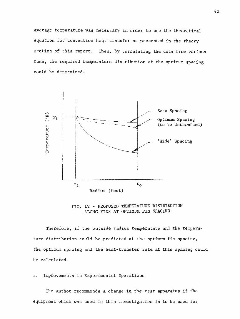
average temperature was necessary in order to use the theoretical
equation for convection he4t transfer as presented in the theory
section of this report. Then, by correlating the data from various
runs, the required temperature distribution at the optimum spacing
could be determined.
r· ~
Radius (feet)
Zero Spacing
Optimum Spacing (to be determined)
'Wide' Spacing
FIG. 12 - PROPOSED TEMPERATURE DISTRIBUTION ALONG FINS AT OPTIMUM FIN SPACING
Therefore, if the outside radius temperature and the tempera-
ture distribution could be predicted at the optimum fin spacing,
the optimum spacing and the heat-transfer rate at this spacing could
be calculated.
B. Improvements in Experimental Operations
The author reconn:nends a change in the test apparatus if .the
equipment which was used in this investigation is to be used for
40

further studies. The steam exhaust from the insulating tank should
be taken from the bottom, instead of the side, of the tank. This
would eliminate the heat-loss rate from the collection tank to the
condensate within the insulating tank.
The author also recommends that the test apparatus be placed
in a room where the ambient temperature may be held constant through
out the investigation.
41

BIBLIOGRAPHY
1. Brown, Aubrey I. and Marco, Salvatore M., Introduction to Heat Transfer, third edition, McGraw-Hill Book Company:-Inc., New York, 1958.
2. Durham, Franklin P., Thermodynamics, second edition, PrenticeHall, Inc., New Jersey, 1961.
3. Elenbass, W. "Dissipation of Heat by Free Convection," Parts I and II, Philips Research Report~' N. v. Philips' Gloeilampenfabrieken, Eindhoben, Netherlands, 1948, pp. 338-360 and 450-465.
4. Elenbaas, w., Physica 9, 1, 1942.
5. Elenbaas, W., Physica 9, 865, 1942.
6. Hamilton, D. C. and Morgan, w. R., National Advisory Committee for Aeronautics, Technical Note 2836, Purdue University, December 1952.
7. Hartog, J. P. Den, Advanced Strength of Materials, McGraw-Hill Book Company, Inc., New York, 1952.
8. Higdon, Archie, Ohlsen, Edward H., and Stiles, William B., Mechanics of Materials, John Wiley and Sons, Inc., New York, 1960.
9. Holman, J. P., ~Transfer, McGraw-Hill Book Company, New YGrk, 1963.
10. Keenan, Joseph H. and Keyes, Frederick G., Thermodynamic Properties of Steam, thirty-sixth printing of first edition, John Wiley and Sons , Inc., New York, 1964.
11. Kreith, Frank, Principles of Heat Transfer, second edition, International Textbook Company, Pennsylvania, January 1966.
12. Laschober, Robert R. and Sward, Glenn R., ASHRAE Paper 2028, "Correlation of the Heat Output of Unenclosed Single and Multiple-Tier Finned-Tube Units," February 16, 1967.
13. McAdams, w. H., Heat Transmission, third edition, McGraw-Hill Book Company, Inc., New York, 1954.
14. Schneider, P. J., Conduction Heat Transfer, Addison-Wesley Pub- · lishing Company, Inc., Massachusetts, 1957.
42

VITA
The author, Glenn Ellis Miller, was born on August 6, 1944,
in West Plains, Missouri. He received his elementary and high school
education at Mountain View Public Schools located in Mountain View,
Missouri. From September 1962, to June 1966, he attended the Uni
versity of Missouri at Rolla. Upon graduation with a Bachelor of
Science Degree in Mechanical Engineering, the author was commissioned
a 2/Lt., USAR. He obtained a delay of active duty with the U.S.
Army and received an appointment as a Graduate Teaching Assistant
in the Mechanical Engineering Department at the University of Missouri
at Rolla for the academic year 1966-67, while he began working toward
an M.S. Degree in Mechanical Engineering. On June 3, 1967, the au
thor married Joy Earle Meserve of Independence, Missouri.
43

44
APPENDIX A
DERIVATION OF HEAT - CONVECTION COEFFICIENT THEORY (2)
A differential equation describing the motion of the convection heat-
transfer boundary layer within the laminar flow region has been obtained
by using a momentum analysis along with an energy equation. Both of these
equations were derived for an elemental control volume within a laminar
portion of the boundary layer.
The momentum equation is derived by writing a balance for the momen-
tum flux in the direction parallel with the vertical surface, referred to
hereafter as the x-direction. The momentum flux is the product of the mass
flow and the component of velocity in that direction. By equating the sum
of the external forces in the x-direction to the change in momentum flux
through the control volume and by using the continuity relation
(~ + ~ _ O), the momentum equation becomes: ax ()y-(1) ~ + v.a£l =
p L ax a yJ a2~ _ ..eE. _ g
lJ aY ax P •
By using ~ = iPg and expressing the density difference in terms of the ax c:o
volumetric coefficient of thermal expansion, .f3, the equation takes the form:
(2) = g p S::T - T a ) .tc , ja 2
~· The velocity component normal to the surface is neglected and the
momentum equation, integrated over the boundary layer thickness ( 1), is
expressed as :
(3) d dx
= t +[j) g S(T-T a) dy •
0
The velocity and temperature distributtons within the boundary layer
are obtained by applying boundary conditions to equation (3). The temp-

erature distribution is given as ;
(4) = 2
(1 - } )
The velocity distribution is obtained by assuming the velocity to
be a polynomial function of y multiplied by an arbitr ary function of x.
Denoting this arbitrary function of x as ux, a fictitious velocity, the
velocity distribution is shown as;
(5) u
ux = y 6
(1 - 1.. )2 6 .
45
Inserting these expressions for the velocity and temperature distri-
butions into equation (3) and carrying out the mathematical operations
gives :
(6) 1
105 d dx =
The energy equation is obtained by considering the elemental control
volume within the laminar boundary layer with the following assumptions.
1. Incompressible , steady flow
2. Constant viscosity , thermal conductivity, and speci f ic heat
3. Negligible heat conduction in the direction of flow
Writing an energy b alance gives the energy equation for the laminar
portion of the boundary layer:
(7)
The term containing the viscosity , ~' may be neglected when consider-
ing free convection because the velocity is so low. This low velocity
causes the viscous work term. to be negligible in comparison with the eon-
duction term. So for free convection the energy equation becomes :
(8) u v a T a Y
= '. CL t
Integrating this with respect toy gives :

(9) L [ f u(T - Ta )dy] dx o
= ,.. dTJ ""'t-dy y ::: - 0
Now substituting the velocity and temperature distributions into
equation (9) gives ;
(10) 1 (T - Ta ) 30 w
46
The differential equations (6) and (10) are solved simultaneously by
assuming that both Ux and S have
m and S = xn These constants are evaluated as: ux = c1 x c2
(11) cl = s. 17v~O ~r~ [ g a <Iw - Ta) J \ , and + 21 v
wa ~r [ g B . . Tw- T8 ) J -t ~r~ (12) c2 = 3. 93 21 + v 2 at
From these calculations, the boundary layer ~y be expressed as a
function of the distance from the edge of the surface in terms of the
Prandtl and Grashof numbers as;
(13) -x- = 3.93 -\
Pr t
(0. 952 + Pr) •
From Fourier's Law and the temperature distribution in equation (4),
the value of the heat convection coefficient may be evaluated.
(14) qw = - kA dT = hA ('fw - Ta) • dy
(15) h k dT (T - T ) ( 2) 2k = - Oy k = - - f r ,.
(Tw - Ta) w a
Tw - Ta
Since Nusselt's number is defined as~ = ~, then the heat-con
vection coefficient may be expressed in terms of the following dimension-
less equation:
(16) 0.508 Pr \ (0.952 + Pr)-~ Grx ~.
For much experimental work, the value for the average heat-convection
coefficient has been expressed as :

(17) hL = Nu k
=
47
C (Gr Pr)m )
where the properties are evaluated at the mean film temperature, defined
as :
(18)
The values for C and m have been determined experimentally by
McAdams Q]) for various ranges of the Grashof - Prand tl number product.

APPENDIX B
SAMPLE CALCULATION FOR HEAT TRANSFER BY CONVECTION FROM THE END OF THE FINS
48
ThesA calculations were for zero spacing between the fins and a sur-
face temperature of 350°F with an ambient temperature of 90°F. The pro-
perties of air were evaluated at the mean film temperature, Tf.
as ;
Tf T + Ta 220°F = w =
2
p = p/RT = 0.0565 lbm/ft3
cP = 0.241 BTU/lbm - OF
~ -- 0.053 lbm/hr - ft
k -- 0.0178 BTU/hr - ft - OF
!3 = 1.48 X 10⁻³ oF-1
Pr = cP lJ = 0. 718 --
k
Grd = g S('}'"w - Ta) P
~
PrGrd = 0.384 x 10⁸
Nu = C(G Pr) m rd
2 3 d = 5.35 X 10 7
McAdams (13) has evaluated the constants C and m for 104~PrGrd~109
c = 0.53 and m = 0.25 )
Nud = 41.8 )
he = k Nud 1.15 BTU/hr ft2 OF = - - . d
The convection coefficients for the various fin spacings required
different values because of the change in surface temperature of the fins.

49
Holman (i) gives the following simplified equation for air at atmospheric
pressure when 104 PrGr 109 and the flow of air is laminar: ~
he = 0. 27 tAd r:.J

APPENDIX C
CALCULATION FOR CONVECTION HEAT-TRANSFER RATE FRCM LATERAL FIN SURFACES AT 'WIDE' FIN SPACING
The temperature distribution along a single fin is given by the
following Bessel equation: ~
~0 "" fi0 (Nr) K1 (Nr2c) + Il (Nr~) 'Ko (Nr) J ~0 (Nr 2)K1 (Nr2c) + 11 (Nr~) ~ (Nri)
To ::~ tw- ta ... 275°F1
ri = 0.0544 ft'
r2c = 0.333 ft,
k = 27.0 BTU/hr-ft-°F1
s ::: 0.0104 ft,
N ., Jh/k f ) and
h is to be determined.
, where
The temperature at the end of the fin may be evaluated by setting
r = r 2 = 0.323 ft ;
'J2 = 275 [I0 (. 610 '\l'fi) K1 (. 629 lEi)
I 0 (. 1025 In) K1 (. 629ifi)
+ 11 (. &29 lfi) Ko (-. 610 .Jfi) l + 11 (. 629 In) 1(0 (. 1025 v"fi~ .
The average heat convection coefficient may be expressed in terms
of the average surface temperature as:
\ = 0.3235 CTavg> .
The average surface temperature was next expressed in terms of the
end temperature. If the heat convection coefficient is assumed to be
constant over the fin surface, then the expression for the temperature
distribution is a straight line on log-log paper and may be expressed
50

in a power form:
T(r)
where = T at r = 1.0, and
m = slope = 0,'562 (ln T 2 - 5. 61) •
c1 was also evaluated in terms of T2 •
= 1 A
T -1. 058m c1 = '8.e
[ m+£ r2
Since T2 was the only unknown, the value of T~ was solved for by
trial and error methods:
Assume
m =
cl =
Tavg =
nc =
hr =
hT =
163°F J
-0.2835)
222 )
173 )
1.171)
4 4 /Tavg ~a- Ctavg ta ) = 1.17)
2.341 BTU/hr-ft2_oF,
[10 (. 940) K1 (. 970) +
1 0 (. 158) K-1 (. 970) +
11 (. 970) ~0
I1 (. 970) K -o
(.940)-J = (. 158)
The heat-transfer rate by convection from th:e lateral surfaces of
one fin at 'wide' spacing was calculated as:
= 129 BTU/hr-fin •
51

FIN SPACING (INCHES)
LENGTH OF SECTION (INCHES)
NUMBER OF FINS
ROOM TEMPERATURE (oF)
FIN TIP TEMPERATURE (oF)
TIME OF RUN (HOURS)
VOLUME OF CONDENSATE (MILLILITERS) ,
TOTAL HEAT-TRANSFER RATE (BUT/HR)
HEAT-TRANSFER RATE (BUT/HR-FIN)
HEAT-TRANSFER RATE (BTU/HR-FT)
0
APPENDIX D
EXPERIMENTAL RESULTS
1 I6
1 8
! I 3 l i 16 I
i
1 4
5 16
3 -8 7
16 1 -2
5 8
3 4
1
8.5 10.75 0.0 ~1.625 13.24, 4.875 16.5 8.125 19.75 23.0 33.25 32.75 31.75
34 34 27 27 27 27 27
83 88 94 93 93 88 98
349 345 338 312 291 285 284
2 2 2 2 2 2 2
27 27 27 34 27 19
92 93 98 97 90 97
282 278 283 272 275 272
2 2 2 1 1-2
2 2
1568 1821 2117 3330 4686 5569 5854 6217 6544 6628 6261 7265 5300
900 1140 1410 2540 3800 4620 4890 5230 5510 5600 7210 6200 4360
26.5 33.6 52.3 94.1 141.0 171.0 181.0 ~94.0 204.0 207.5 212.0 229.0 ~30.0
1270 1270 1690 2620 3440 3730 3550 3470 3350 2920 2600 2280 1650

APPENDIX E
THEORETICAL RESULTS
1----T·----r- ---- ------ -- r- --
FIN SPACING I 1 1 3 1 5 3 7 1 5 3 1 1.!.
(INCHES) 0 16 8 , I6 i 4 16 8 16 2 I 8 4 2
244 1 219 i 202 ! ; I 175 TEMPERATURE DIFFERENCE I 266 257 ! ! 195 l 190 187 184 181 178 I 175
(FROM GRAPH) (oF) I I I ' I I l I i
i ' I SHAPE FACTORJ I 0 .9845 .9692 .9542 .9395 . 9249 .9106 .8965 .8826 .8557 . 8295 l· 7795 .6890 I
I
F1-2 I I i
RADIATION FROM BETWEEN FINS 0 5. 78 (BUT/HR-FIN)
10.6 13.3 15.5 18.4 21.0 23.6 26.3 31.4 36.4 45.9 64.5
FLOW RATE FROM END OF FIN 26.6 26.3 24.4 20.9 18.6 17.8 17.1 16.8 16.4 15.9 15.7 15.2 15.2 (BTU/HR-FIN)
FLOW RATE FROM TUBE 0 1. 08 2.16 3.23 4.30 5.40 6,46 7.55 8.63 10.8 12.9 17.3 25.9 (BUT /HR: .. FIN)
CO~CTION FROM E EN FIN ~BT RR-FIN~ 0 0 15.1 56.7 102.6 129.4 136.4 146.0 152.7 149.4 147.0 150.0 130.0
eoNVECTION FROM 0 0 490 1590 2510 2820 2740 2610 2.500 2110 1800 1490 850 -l~m~--;~~s
. ~ -t· , . -
- EF~C:lENCY OF THE F.I~D ' S'E-CT!ON (%) r34 34 46 . ' 71 92 100 97 93 87 78 71 61 44
- ' . -


![EXPERIMENTAL STUDY FOR OPTIMUM FIN SPACING OF …jestec.taylors.edu.my/Vol 15 issue 6 December 2020/15_6... · 2020. 12. 17. · Shehab [15] investigated experimentally the effect](https://static.fdocuments.net/doc/165x107/60ab62affefaa02fb92d3303/experimental-study-for-optimum-fin-spacing-of-15-issue-6-december-2020156.jpg)