Optimum design of magnetic braking coils with special ... · tech library kafb, nm nasa tn d-3132...
26
NASA TECHNICAL NOTE NASA TN D-3132 --- (73 / OPTIMUM DESIGN OF MAGNETIC BRAKING COILS WITH SPECIAL APPLICATION TO LEWIS DROP TOWER EXPERIMENTS by H. G, Kosmahl Lewis Research Center Cleveland, Ohio NATIONAL AERONAUTICS AND SPACE ADMINISTRATION WASHINGTON, D. C. DECEMBER 1965 https://ntrs.nasa.gov/search.jsp?R=19660003939 2018-07-21T20:52:34+00:00Z
Transcript of Optimum design of magnetic braking coils with special ... · tech library kafb, nm nasa tn d-3132...

NASA TECHNICAL NOTE N A S A TN D-3132 - - - (73 /
OPTIMUM DESIGN OF MAGNETIC BRAKING COILS WITH SPECIAL APPLICATION TO LEWIS DROP TOWER EXPERIMENTS
by H. G, Kosmahl Lewis Research Center Cleveland, Ohio
N A T I O N A L AERONAUTICS AND SPACE A D M I N I S T R A T I O N WASHINGTON, D. C. DECEMBER 1 9 6 5
https://ntrs.nasa.gov/search.jsp?R=19660003939 2018-07-21T20:52:34+00:00Z

TECH LIBRARY KAFB, NM
NASA T N D-3132
OPTIMUM DESIGN O F MAGNETIC BRAKING COILS WITH SPECIAL
APPLICATION T O LEWIS DROP TOWER EXPERIMENTS
By H. G. Kosmahl
Lewis R e s e a r c h Cen te r Cleveland, Ohio
N A T I O N A L AERONAUT ICs AND SPACE ADMINISTRATION
For sole by the Clearinghouse for Federal Scientific and Technical Information Springfield, Virginia 22151 - Price $1.00

OPTIMUM DESIGN OF MAGNETIC BRAKING COILS WITH SPECIAL APPLICATION TO LEWIS DROP TOWER EXPERIMENTS
by H. G. Kosmahl
Lewis Research Center
SUMMARY
General analytical treatment of a design of magnetic braking coils and magnetic brak- ing action is given. However, numerical results are computed and tabulated only for the specific application and requirements of the Lewis Research Center (400-ft) drop facility.
been developed. Braking action has been computed for the case of a primary coil used to stop the motion of a secondary coil moving along the common axis and with a given mass and initial kinetic energy. The amount of deceleration can be adjusted by varying only the primary voltage (current). The preceding tasks may be accomplished with a primary system requiring a minimum number of turns.
For the specific case of a freely falling payload in the Lewis 400-foot drop facility, weighing 1000 kilograms and having a final velocity of 50 meters per second, a primary power of between 10 to 20 megawatts associated with a primary current of about 100 kilo- amperes is required for 10 seconds to stop the payload with a deceleration equal to or less than 30 g's. The corresponding primary magnetic field is of the order of 1 Weber per square meter (10 000 gauss).
the least energy for a given maximum deceleration. the equations involved, additional computations may be necessary for numerical cases not tabulated in this paper. is not feasible.
A method for calculating the mutual inductance of unconventionally wound coils has
The energy required in the primary coil can be minimized.
A primary coil with a linearly increasing winding density has been found to require Because of the nonlinear nature of
For the same reason, a closed form optimization procedure
INTRODUCTION The use of magnetic brakes in many industrial and scientific applications is a well
established practice. The mechanism of operation can be best explained from Lenz*s law which says that magnetic fields induced in one circuit as a result of interaction with another circuit oppose each other.
The purpose of the present investigation is to find a configuration of a primary mag- netic coil (in the following coil 1) and of a secondary coil 2 such that the motion of coil 2 through fields of coil 1 can be brought to a stop under controlled conditions requiring

minimum primary energy. the drop experiments in Lewis Research Center zero-gravity drop tower facility) the payload falling freely through a height of 120 meters approaches a speed of about 50 meters pe r second. It must be decelerated to almost a perfect stop with the deceleration not to exceed a specified maximum. The solution of this and other similar problems requires the knowledge of the mutual inductance M between two unconventionally wound circuits as functions of distance between them. (Symbols are defined in appendix A. ) The deter- mination of M (appendix B) was accomplished by expanding a number of winding density functions (winding schemes) in a complex Fourier integral and applying them to a Bessel integral expansion of the vector potential. From the latter the mutual inductance and the self inductance can be determined.
The circuit equations as well as the equation of motion of the payload in magnetic and
For the particular application being considered herein (i. e.,
gravitational fields a re then solved on a computer and an optimization of the coil system with respect to minimum energy and minimum size is carried out.
ing a minimum of primary energy, in which the braking action is accomplished in a pre- cisely adjustable manner with respect to the desired degree of deceleration by simply varying the voltage of the primary circuit and/or the length of the primary coil.
The significance of these results l ies in the possibility of designing a system requir- c
ANALYSIS OF MAGNETIC DECELERATION
The interaction of two, predominantally magnetically coupled coils can be best described by their mutual inductance M. Figure 1 shows two magnetic coils denoted by subscripts 1 and 2. Coil 1 is connected to a power source with the load voltage Vo and an impedance R << R1. The origin of the coordinate system z = 0 represents the (physical) end of coil 1, the latter being immobile. Coil 2 is short circuited and is assumed to move only in the z-direction, which points in the direction of the earth% gravitation.
A magnetically noninteracting mass mo is affixed rigidly to the turns of coil 2. latter has a mass m2 so that m = m + m2 represents the fu l l mass of the second coil. Suppose that a steady-state current i flows in coil 1 prior to any interaction with coil 2. If the latter is permitted to fall in the negative z-direction due to gravitational force and its momentary distance from z = 0 is z, the following equations a r e applicable to determine the instantaneous velocity i z(t)
g
The
0
1YO
of the second coil: [ I di2
Vo = il(t)R1 + L1 - dil + __ d ~ ( z ) i2 + M(z) __ dt dt dt
2

Coil diameter
Coil length
Noninteracting mass, mo, (payload) -
Coil 2
Steady-state c u r r e n t 7
Distance between coils:
Symmetrically Arbi t rar i ly wound coi ls wound coi l 1 and
symmetrically wound coil 2
i i 4 I
I I \
Open c i r c u i t voltage -,,
Generator resistance Rg-,
I Coil 1
Figure 1. - Schematic arrangement of coi ls 1 and 2 for fa l l ing payload.
The repelling magnetic force Fm acting upon the turns of the falling payload is
where z is the distance between defined points in coils 1 and 2. of the payload is
The equation of motion
3

Multiplication by k and integration between t = 0 and t = t (fig. 1) result in the energy equation
Ir t=t
Jt=o
and i2(0) = 0. since h(O), the velocity at z = h, is zero. The initial value conditions are il(0) = io
After M = M(z) has been computed with the help of relations derived in
I
Distance, x, m
Figure 2 - Typical plots of velocity, secondary current, and normalized force against distance between coils. Winding density, w1 = 8(1 -g). 8
appendix B, equations (l), (2), and (5) are solved simultaneously for z(t) and k(t). The values k(ts) = 0 and z(ts) give the stopping time ts and the stopping position z(ts) = xs of the payload. data contained the currents il and i2, M[z(t)] and aM[z(t)]/az(t), the normalized force G = (ili2 aM/az)/mg, the inductances L1 and L2, the re- sistances R1 and R2 that havebeen computed as functions of the coil diam- eters 2a and 2b, wire diameters dl and d2, the winding density w1 and w2, the coil lengths Z and Z,, and the specific resistivities p1 and p2 of the coil wires.
Notice that the decelerating force persists even after k has reached zero (fig. 2) because the time constant T~ = L2/R2 prevents an instantaneous decay of i2 tozero. Thus, Fm remains finite over a period of a few constants, and a '?perfect" stop is possible.
has been assumed to which the mass of aluminum turns affixed to the payload has been added. Because of specific
The total output of computer
A payload mo of 900 kilograms
4
I

requirements the diameter of the primary coil has been kept constant at 2a = 3 meters. The primary turns consisted of 0. 1-meter-diameter copper wire throughout with a spec- ific resistivity of 1. 8X10⁻⁸(S2)(m).
DISCUSSION OF RESULTS
The more important computer results have been presented in table I. In addition to geometrical parameters they contain the primary coil voltage V1, the steady-state pri- mary current i at the beginning of interaction, the power P, the normalized force G in multiples of g, and the position xs at which the center of the payload turns ap- proaches zero velocity, measured from the bottom end of the primary coil z = 0. Also listed a r e two values of the specific resistivity p2 for aluminum which have been assumed to be 3 ~ 1 0 - ~ (S2)(m) at room temperature T = 300' K and 0. 6 ~ 1 0 - ~ (S2)(m) at T = 80' K (liquid nitrogen (unpublished data, obtained by John C. Fakan of Lewis, show values as low as 0. 3X10⁻⁸(S2)(m)). It should be noted that the primary current il is not absolutely constant; however, because of the relatively large time constant T ~ , the current il changes by less than 10 percent of the initial i
The maximum temperature r ise in the secondary turns was less than 25' C, with an average of approximately 10' C, rendering this effect entirely unimportant.
Table I refers to three different winding schemes. preferable over the others the primary power must not be the sole criterion because of the presence of restraining conditions and ease of construction. in drop tower applications are: the time constant T~ to be as small as possible in order for the current il to build up as close to its final value i t < - 10 seconds. height h equal to 120 meters, the time t = 10 seconds being the maximum period avail- able for the buildup of current in case of a two way 'tup and downtP experiment.
The other conditions for the Lewis Research Center drop tower experiments is the upper limit of deceleration G to be smaller than 30 g's. The computations show clearly that the power requirements to bring about a f u l l stop could be reduced substantially if the condition G < - 30 were disregarded because stopping action could then be accom- plished with a shorter primary coil.
1, 0
value. 1, 0
For deciding which scheme is
Two important conditions
as possible in a time 190
The latter number is approximately twice the free fall time through a
An evaluation of the tables leads to the following important conclusions: (a) Application of liquid-nitrogen cooling to the secondary turns reduces sub-
stantially (50 to 70 percent) primary power requirements in the case of d2 = 0.05 meter and only slightly (about 15 percent) in the case of d2 = 0. 1 meter for the assumed value of specific resistivity.
(b) Primary power requirement decreases rapidly as b is increased (while keeping a = 1.5 m constant) from 0.75 to 1.0 meter.
5

Secondary coil
specific resistivity,
P2’ (n)(m)
Secondary coil
winding density,
w, turns/m
Primary coil
voltage
V VI,
Initial current,
il A
Maximum normalized
force,
Gmaxy
Stopping Power, distance, P,
XS’ M w
m
Second- ary coil
radius, b, m
Second- =-Y coil
length,
m 1 2’
8 8 8 8 8 8 8 8 8 8 8 12 12 8 8 8 8
0.05 . 10 . 10 .05 . 10 .10 .05 . 10 . 10 . 10 . 10 .05 .05 .10 . 10 . 10 . 10
107 98 91 124 141 138 146 135 131 128 125 170 237 123 122 128 135
123.8 113.4 105.3 144.0 163.2 159.7 169.0 156.0 151.0 148. 2 144.7 131.0 183.0 142.0 141.0 148.0 156.0
1.00 0. 6
1 .I . 8 . 8
1. 0 1. 2 1. 6 . 6 . 6
1. 2 1. 2 1. 2 1. 2
0. 6 . 6
.75 .6 . 6 3.0 .75
175 185 232 201
TABLE I. - COMPUTER RESULTS AND COIL PARAMETERS
8 [Primary coil radius, 1.5m; primary coil specific resistivity, 1.8X10- (n)(m); primary coil conductor diameter, 0. lmq J
Primary coil
length, 1 1’ m
S econdar j coil
conductor diameter,
m d2’
Primary coil time
constant,
71’ sec g I I
Pr imary coil winding density, 10 1 - - ( I f )
I 13.3 11. 1 9. 6 11.8 23. 0 22. 0 24.7 21. 1 19.9 19.0 18. 1 22. 4 43. 3 17. 5 17. 2 18. 9 21. 1
29.8 30. 2 30. 3 30. 2 29. 6 29. 5 29. I 29.8 29.8 30.0 31.0 19. 2 19.8 29.5 29. 6 29.8 30.2
0. 65 1. 96 1. 87 2. 20 2. 10 1.93 .06 . 10 1.90 1.95 2. 20 1.2 .85
1.80 1.90 1.95 2. 10
3. ox108 3.0
. 6
. 6 3.0
.6 ! 3.0
i
6 2.3
3. 55 3.55 2.3 2. 3 2. 3 2. 3
2 4 6 8
~
Primary coil winding density, 2 1 + 5 cos 2 ( znl)
6 0.15 0. 6 134 170 149 19 1 257 20 1
93.0 119.0 103.0 88.0 119.0 93.0
39.0 44. 1 41. 3 27.0 32.0 26.0
4.5 5.0 4.9 7.0 I. 8 6. I
12. 5 20.0 15. 5 16. 8 30. 6 18. I
3.46 3.46 3.46 3.65 3.65 3. 65
.05 .6
12 .10 .6
Pr imary coil winding density, 2 1 + 5 1 - [ 91 96. 4 102.0 127.6 110. 5
27. 6 27. I 29. 6 27.3
6.9 6.8 7.6 6.9
16.9 18.9 29. 6 22. 2
3.22 3.22 3. 22 3.22 -
6

(c) For equal values p2, d2, Z2, w2, and b, respectively, while keeping G < - 30, the power requirements of the three tabulated winding schemes necessary to bring about a full stop are about the same. (The energy requirements, however, a r e not equal. )
71 = 2 . 3 seconds and requires the smallest number of turns to bring about a "full stop" of the payload.
The meaning of fu l l stop, as used herein, refers to a motion in which the velocity decays directly to zero, without oscillations in the sign of the deceleration (i. e., no ac- celeration). Notice that the position of stop xs in all symmetrically wound coils lies above the coil center z = Z1/2. inductance M has a maximum and aM/az = 0 at the center of the coil. Thus aM/ZIz reverses its sign in going through the center. Now, in the expression for the force (eq. (3)), il(t) remains almost constant and the sign of i2 depends mainly on that of aM/az. Because the time constant 72 is rarely below 0. 1 second in this particular de- sign, a reversal in the sign of aM/az in going through the center would precede that occurring in i2. Therefore, if the payload moved over the center, a short period of ac- celeration would follow: the payload velocity would increase temporarily before final deceleration could occur to cause the final stop. Such a *%NO phase" deceleration with a short acceleration period in between has been examined on the computer and seems to produce a workable mode of operation requiring approximately 10 percent less power than "one phase" stopping. ambiguous than that of "one phase" stopping and has not been considered in this discus- sion.
(d) The winding scheme w1 = const[l - (z/Z)] produces the shortest time constant
This happens because in symmetric coils the mutual
The evaluation of the '%NO phase" cases, however, is more
The effect of changing I? on the power requirements indicates an optimum length I, < I,. This result is easily explained by the fact that two competing factors produce
On the other hand the mass m2 increases propor- a minimum power requirement: increasing I, increases the flux through the secondary and, therefore, the braking force. tionally with I? and reduces the effect of the decelerating force in front of the integral (eq. (5)).
The highest computed value I, is
flattens out and an increase of power requirements with increasing I?, is likely to
I, = 3. 6 meters at which number the primary power requirement is still decreasing slightly; however, the dependence of P against
occur at some large value of cation.
table I. This optimum occurs because of the competing effects between the secondary time constant T~ which prevents a rapid build-up of i2 and of the mutual inductance
I I?,, which is of little practical interest to the desired appli-
A clear dip in power requirements appears if w2 is changed, as can be seen from
- Since both T~ as well as M increase with increasing w2, a minimum in
the required power occurs if the total interaction time is not substantially larger than M1, 2' 192
0
7 2
7

11ll1lll1l1111l11l11ll IIIIIIIII I I I I
36
32
28
24 a- 2 0 L
E m ._ - m L E 0 z
16
12 8/-i 4
0 2
\
I I I I t i i i
I I I I I I .I I I Curve p r imary coil Primary Primary
winding coil density, length,
W1J t u rns lm
i f
t
..
L
\ i,
\ -
L \ \ \ \
I L
10
I
\ ? \ t \ t I
- 12
I
\ \ \
14 tance, x, m
Figure3. - Normalized force against distance for three different winding schemes. Secondary coil wind- ing density, 6 t u r n s per meter; secondary coil length, 0.6 meter; secondary coil radius, 0.75 meter.
Because of the approximate constancy of il the primary energy requirement is pro- portional to ilTb, where T~ is the braking time. The smallest braking time is accom- plished with a steplike-shaped deceleration of maximum permissible amount over the time Tb and which is zero elsewhere. Figure 3 shows the normalized magnetic deceleration G against distance for two different geometries. The length of coil 1 wound according to w1 = l O ( 1 - z/l l) is 1 w1 = 2(1 + 5 cos sz/ll) is I , = 12 meter. The difference in coil length is necessary in order not to exceed G = 30, as may be seen from comparing curves 2 and 3 in figure 3. A comparison of the curves shows that curve 1 except for the exponentiallike tail, more closely approaches the steplike function than curves 2 and 3. The latter resemble rather re sonanc elike curves.
8
2
= 8 meter; that of coil 2 wound according to

0
.o-
I I
1 i I 0
I I
I I I
/
2
coil I- i ng density, + W11 t u r n s l m
1 Constant, uni- i- formly wound
---- 4 l O ( 1 -
a Distance, x, m
Figure 4. - Derivative of mutual inductance against distance for four different winding schemes. Secondary co i l winding density, 6 t u r n s per meter; secondary coi l length, 0. 6 meter; secondary coi l radius, 0.75 meter.
Figure 4 shows aM/ax against x for a variety of winding schemes; x is the dis- tance from the center of coil 2 to the center of coil 1 in symmetrically wound primary coils and from center of coil 2 to the remote end of coil 1 for the winding scheme w1 = 10[1 - (z/Zl)]. A uniformly wound solenoid produces the narrowest, the 1 - (z/ ZI) winding scheme the closest to rectangular o r steplike shape. aM/i3x is much wider than the deceleration G in figure 3. Both a r e plotted on the same scale of x. This behavior results from the existence of a time constant T~ which is not substantially smaller than the braking time Tb. Thus, there is a delay before the maxi- mum of i2 can develop and the width of G is shortened (fig. 2).
as functions of w 170 for the winding density w1 = wl, o[l - ( z / Z ~ ) ] . AS w 1, the power necessary to produce a fu l l stop, P1 decreases over the examined range. On
Figure 4 shows that
Figure 5 shows P1, T ~ , Gmax and the primary number of ampere turns plotted increases
9

+- c m c
._ 0 V
2,
E
a ._ L
L m E .- L a
1.5- - 3 0
= 2 1.0-
L W
- ._ :: 2, L m E .- L n.
ci- W- V L 0
-0 0) N
m L
L
._ - E 0 c
5
z E ._ x
Stea
,-Maximum ,, normalizec
force - - i t - imberof -
ampei
Powe
tur
I 8 -
I I I - - . 16
state winding density, w 1 0, t u r n s l m I
Figure 5. - Power, t ime constant, normalized force, and number of ampere t u r n s as funct ions of steady-state winding density for pr imary winding density required to stop payload. Pr imary co i l length, 8 meters. Secondary coi l parameters: winding density, 6 t u r n s per meter; coi l length 1.2 meters; coi l conductor diameter, 0. 1 meter; specific resistivity, 3x10-d (RNm).
the other hand Gm, remains constant (Gm, = 30g) as does the total number of ampere turns
It can, therefore, be concluded that as long as Zl and the total number of ampere turns a r e kept constant G,, will not change.
A practical limitation in the reduction of PI is twofold: the increase in T~ (which could be irrelevant in other cases) and the necessity to increase the radius of the turns. Also, at some point the change in il must be considered, and the integral
10

must be used for primary energy calculations. out. Its minimum lies beyond the range T~ which is of interest for the considered ap- plications.
f igure 2 (p. 4) is a plot of the velocity k , the secondary current i2, and the force G against x. Note that at x = xs the payload comes to a stop (i. e. , 2 = 0), but both i2 and G are different from zero, which makes a perfect stop possible. The shape of G follows closely that of i2. Because of the constancy of il this is only possible if aM/ax remains approximately constant, in agreement with curve 4 in figure 4.
The power curve Pl in figure 5 flattens
CONCLUDING RWARKS
A design of a magnetic coil system in applications as a magnetic brake has been in- vestigated and a method for calculating the mutual inductance and self-inductance of non- conventionally wound coils has been developed. minimum primary energy requirement to bring to a stop a payload with a given initial kinetic energy, production of a smooth deceleration in a steplike function with the degree of deceleration being easily adjustable by changing only the primary voltage and/or pr i - mary coil length I,, accomplishment of the preceding tasks with a primary coil having as few turns as possible, and a required flux density equal to about 1 Weber per meter squared (10 000 gauss).
A very definite optimum design has been determined under the imposed restrictive conditions (i. e. , maximum deceleration and coil diameter ratio). eters for minimum power requirement is generally noncritical; however, deviations of a factor of 2 in some of the parameters f rom their optimum value may render the system infeasible.
unless stability studies, not carried out in the frame of this investigation, produced in- formation to the contrary.
be designed to fu l f i l l the double purpose of launching and stopping the payload within the very same coil, thus eliminating the need for mechanical launching guns.
The main features of this brake a r e
The choice of param-
It is concluded that an elegant, efficient, and reliable system could be developed
Although not discussed herein, it is conceivable that an electromagnetic system could
Lewis Research Center, National Aeronautics and Space Administration,
Cleveland, Ohio, September 9, 1965.
11

I 11ll1llllll11l1l1ll I Ill1 I I1 I1 I
APPENDIX A
SYMBOLS
azimuthal component of vector potential A'
radius of primary coil, m
magnetic flux density, Wb/m
radius of secondary coil, m
general constants
wave number dependent pa-
2
rameter
distance between coils, m
surface element
line element
magnetic force
normalized magnetic force,
9.81 m/sec2
magnetic field strength, A/m
height, m
modified Bessel function of first kind n order and argument k r
F/mg
th
current, A
current per unit length, A/m
modified Bessel function of second kind, nth order and argument k r
Fourier integral wave number
self inductance, H
1 length of coil, m
M mutual inductance between coils 1 and 2, H
m mass, kg
N number of turns
P power, W
R resistance, S2
r radius, m
Fourier amplitude function S(k )
t time, sec
V voltage, V
W winding density, turns/m
X distance, m
Z axial coordinate
ab), O(k) phase angle
6 Dirac's delta function
P specific resistivity, (Q)(m)
P permeability
4~rx10-~ H/m P O
7 time constant, L/R
'b Subscripts:
e external
i internal
max maximum
breaking time

s stopping
cp azimuthal
0 initial
1 primary coil (coil 1)
2 secondary coil (coil 2)
Superscripts: -c vector
* first derivative
second derivative
13

APPENDIX B
DERIVATION OF EXPRESSIONS FOR MUTUAL INDUCTANCE AND
SELF-INDUCTANCE OF COILS WITH CYLINDRICAL SYMMETRY
If it is assumed that the current sheet has a negligible thickness and circulates only of the vector potential
This can be accomplished by applying a suitable winding technique or current in the azimuthal direction cp at r = ro, only one component A will exist. feeding technique.
50
For a coil of radius ro the latter may be represented by references 1 and 2.
The boundary conditions for B and H on the interface r = ro between the internal and external region, denoted by subscripts i and e, respectively, a r e
and
where j (2) is the surface current density per unit length s, cp
(z) = f(z)b(r - ro) for 0 < z < I js, cp
and j turns is a function of z, the following expansion of j is appropriate:
(z) = 0 elsewhere. If only the winding density w(z) but not the current f in the s, cp
cp
14
1

a3
(B6) -ikz i@(k) S(k) = &- 1 JM e w(z)ciz = IS(^) 1 e
From expressions (B4) to (B6) the following equation is obtained for pi = pe = po
15

because the integration over sin from - a ~ to a~ is zero. satisfied only if
Equations (B3) and (B4) can be
With
Io(kr)Kl(kr) + Il(kr)Ko(kr) = - 1 kr
the constants Ci and Ce a r e determined from (B9) and (B10) to
Thus, the expressions for the vector potential (Bl) and (B2) may be written
IS(k) lKl(kro)Il(kr)cos[kz + @(k)] dk cp, i
A
and, similarly,
Mutual Inductance Between Two Coils
Now the relation (B13) and (B14) is applied to calculate the mutual inductance M between coils 1 and 2, each having a constant diameter 2a and 2b, respectively. In addition, the winding density on the second coil is assumed constant (e. g., w2 = const)
16

even though this restriction is not, generally, necessary.
coil (subscript l), there will be w2 dz turns of secondary coil (subscript 2). mutual inductance between the element w2 dz and the entire f lux coming out of the pri- mary coil is
In a distance between z and z + dz, counted from a fixed point z = 0 in the primary Thus, the
where S2 and s2 designate the area and the length element of turns in the secondary coil, respectively. Because A1(z) is constant over the azimuth at a given radius, the following may be written for dM
The integration (B16) over the entire length z2 results in
d+( 12/21 IS(k) IKl(ka)Il(kb)cos kz + @(k) dz (B17) c i M = 4pOabw1w2m l:dk l d - ( 1 2/2)
where d is the distance between a fixed point in coil 1 and the center of coil 2.
S e If - I nd ucta nce of Co i I
The relations developed for calculating M will now be applied to determine the self- This is done by first find- inductances of axially symmetrical coils of constant diameter.
ing the flux linking any turn and then integrating over all turns. Modifying equation (B15) to apply to the very same coil yields
17
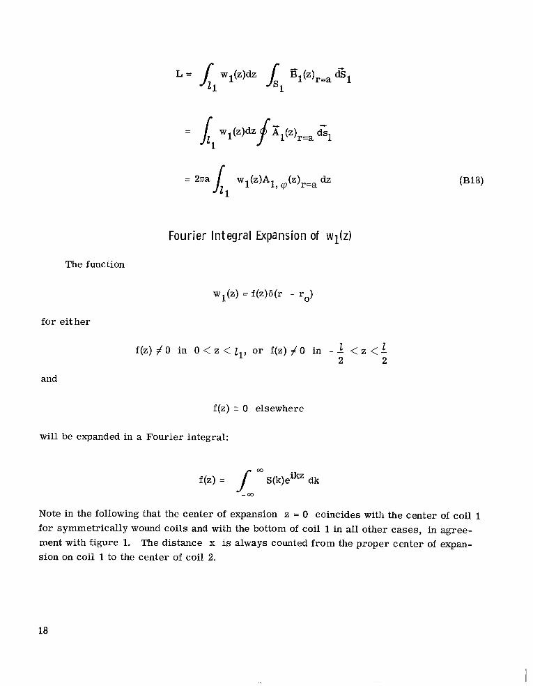
Fourier In tegra l Expansion of w$z)
The function
wl(z) = f(z)b(r - ro)
for either
f(z) # 0 in 0 < z < zI, or f(z) f o in - - 1 < z < - I? 2 2
and
f(z) 5 0 elsewhere
will be expanded in a Fourier integral:
f(z) = f O3 S(k)eikz dk
Note in the following that the center of expansion z = 0 coincides with the center of coil 1 for symmetrically wound coils and with the bottom of coil 1 in all other cases, in agree- ment with figure 1. The distance x is always counted from the proper center of expan- sion on coil 1 to the center of coil 2.
18

1 2 2
= const for - J < z < -
= 0 elsewhere
const e-ikz dz S(k) =- 2a
1 k l = const - sin - ak
and
@(k) = 0
2
1 1 for - - < z < - 2 2
= 0 elsewhere
and
@(k) = 0
cot 2
19
I

ll11l1lIlllIllI I I Ill I I1 I
and
I = 0 elsewhere
i . k l sin -
mk D(k) = -
@(k) = 0 J
= o elsewhere
sin k l - k l tan @(k) = 1 - COS k l J
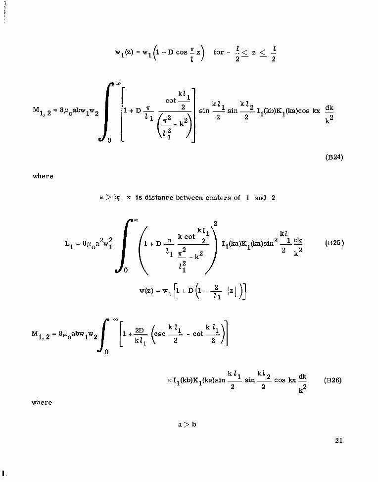
Formulas for M and L for the analyzed function wl(z) a r e as follows:
wl(z) = const
w2 = const throughout
21 l 2 dk Il(kb)Kl(ka) sin - sin - cos kx - 2 k2 2
M i , 2 = 8P0abw1w2
where
a > b; x is distance between centers of 1 and 2
20
k1 1 cot - R 2 L + D - '' sin - 12 Il(kb)Kl(ka)cos kx - dk
k2 2 2 s in -
where
a > b; x is distance between centers of 1 and 2
k l 2 1 dk Il(ka)Kl(ka)sin - -
k2 $1 * k2 2
--
w ( z ) = w l l + D 1 - - I z l ) ] [ ( 1"1 00
M1, = 8pOabwlw2[ [' +% (CSC - 2 11 - cot ")] 2
(B26) kl 2 sin - cos lor - X I,(kb)Kl(ka)sin - k2
k l l 2 2
where
21
I-

0327) L1 = 8p0a2w; 1-1 + E (,sc - 11 - cot - ")-/ Il(ka)Kl(ka)sin 2 k 1 1 - - dk
2 k2 kll 2
w(z) = w1 o(l - -t) for o < z < z1
1, lw f(kZ1)Il(kb)Kl(ka)sin M1, 2
= 8poabw
where
a > b; x is distance between x = 0 on coil 1 and center of coil 2
~ Il(ka)Kl(ka)sin O3 f(kl1)
- 4p0a w1 " 0 k2
Il(ka)Kl(ka)sin - I1 s i n 2
- 1 - cos k l1 sin kZ1 f(kZ1) = -[; 1 +
4- (k q2 I1
sin k l l - kZl tan @(k 11) = for - 2 < a< o
1 - COS kZ1 2 - -
22

REFERENCES
1. Panofsky, W. K. H. ; and Phillips, M. : Classical Electricity and Magnetism. Addison-Wesley Pub. Co., 1955, p. 138.
2. Smythe, W. R. : Static and Dynamic Electricity. Second Ed. , McGraw-Hill Book Co. , Inc., 1950, p. 267.
23

“The aeronautical and space activities o f the United States shall be conducted so as t o contribute . . . t o the expansion of human h o w l - edge of phenomena in the atmoJphere and space. T h e Administration shall provide for the widest practicable and appropriate dissemination of information concerning its actiuities and the results thereof .”
-NATIONAL AERONAUTICS AND SPACE ACT OF 1958
NASA SCIENTIFIC A N D TECHNICAL PUBLICATIONS
TECHNICAL REPORTS: important, complete, and a lasting contribution to existing knowledge.
TECHNICAL NOTES: of importance as a contribution to existing knowledge.
TECHNICAL MEMORANDUMS: Information receiving limited distri- bution because of preliminary data, security classification, or other reasons.
CONTRACTOR REPORTS: Technical information generated in con- nection with a NASA contract or grant and released under NASA auspices.
TECHNICAL. TRANSLATIONS: Information published in a foreign language considered to merit NASA distribution in English.
TECHNICAL REPRINTS: Information derived from NASA activities and initially published in the form of journal articles.
SPECIAL PUBLICATIONS: Information derived from or of value to NASA activities but not necessarily reporting the results .of individual NASA-programmed scientific efforts. Publications include conference proceedings, monographs, data compilations, handbooks, sourcebooks, and special bibliographies.
Scientific and technical information considered
Information less broad in scope but nevertheless
Details on the availability of these publications may be obtained from:
SCIENTIFIC AND TECHNICAL INFORMATION DIVISION
.NATIONAL AERONAUTICS AND SPACE ADMINISTRATION
Washington, D.C. 90546


![REGENERATIVE BRAKING SYSTEM IN ELECTRIC VEHICLES · REGENERATIVE BRAKING SYSTEM IN ELECTRIC VEHICLES ... REGENERATIVE BRAKING SYSTEM ... Regenerative action during braking[9].](https://static.fdocuments.net/doc/165x107/5adccef67f8b9a1a088c7cf0/regenerative-braking-system-in-electric-vehicles-braking-system-in-electric-vehicles.jpg)