Optimizing the Cooling Air Flow of Formula Car
12
Optimizing the Cooling Air Flow of a Formula Car using CFD Lasse Christoffersen, David Söderblom and Lennart Löfdahl Chalmers University of Technology, Göteborg, Sweden ABSTRACT In this case study the cooling airflow of the Ansys supported Chalmers Formula SAE 2007 race car has been improved by the use of Computational Fluid Dynamics. The car had at several occasions experienced over heating during test and the team was looking for ways to improve the cooling performance. The simulations that facilitated the improvements were based on the fully detailed race car where the geometry and fluid domain was resolved with over 40 million cells. The optimization process was performed in several steps tuning both the inlet and outlet of the cooling duct to the suit the exterior flow field. With subtle changes to the bodywork and cooling duct the cooling performance of the car was drastically improved with an over 200% increase in cooling air massflow. INTRODUCTION In motor racing the aim of the driver is almost always to utilize the vehicle to its maximum potential in order to travel a given course in the shortest possible amount of time. This means that the engine should be operating at the highest possible power output the vehicle dynamics and race course allows. To allow continuous operation at such a power output requires adequate engine cooling, which in turn, asks for a sufficient airflow through the heat exchangers of the cooling system. Most commonly the governing body dictates that the air flow through the cooling system has to be ram-driven and the aerodynamics of the cooling ducts and there location becomes extremely important to secure a sufficient flux of air. Furthermore, by optimizing the cooling ducts and airflow, the heat exchangers can be smaller leading to both decreased vehicle weight and aerodynamic drag that in turn will result in decreased lap times [1]. Chalmers University of Technology developed and produced a new car for the 2007 Formula Student competition, which is the British equivalent to the Formula SAE series. During testing it became obvious that the cooling capacity of the car was inadequate as overheating was experienced at several occasions. Therefore, the team wanted to find the reasons and solutions to these overheating problems. Since cooling systems relies on convective heat transfer, securing an appropriate flow of air to the radiator is fundamental to a good heat transfer rate [2]. A first step in the process of solving the problem of overheating was to improve the aerodynamic shape of the racecar in the vicinity of the cooling air inlets. As detailed CAD-data of the car was available it was decided to execute this work by the use of Computational Fluid Dynamics (CFD). Since the bodywork already had been built it was crucial that the necessary modifications did not involve major changes to the vehicle body. EASC 2009 4th European Automotive Simulation Conference Munich, Germany 6-7 July 2009 Copyright ANSYS, Inc.
description
Optimizing
Transcript of Optimizing the Cooling Air Flow of Formula Car
Optimizing the Cooling Air Flow of a Formula Car using CFD Lasse Christoffersen, David Söderblom and Lennart Löfdahl Chalmers University of Technology, Göteborg, Sweden ABSTRACT
In this case study the cooling airflow of the Ansys supported Chalmers Formula SAE 2007 race car has been improved by the use of Computational Fluid Dynamics. The car had at several occasions experienced over heating during test and the team was looking for ways to improve the cooling performance. The simulations that facilitated the improvements were based on the fully detailed race car where the geometry and fluid domain was resolved with over 40 million cells. The optimization process was performed in several steps tuning both the inlet and outlet of the cooling duct to the suit the exterior flow field. With subtle changes to the bodywork and cooling duct the cooling performance of the car was drastically improved with an over 200% increase in cooling air massflow. INTRODUCTION
In motor racing the aim of the driver is almost always to utilize the vehicle to its maximum potential in order to travel a given course in the shortest possible amount of time. This means that the engine should be operating at the highest possible power output the vehicle dynamics and race course allows. To allow continuous operation at such a power output requires adequate engine cooling, which in turn, asks for a sufficient airflow through the heat exchangers of the cooling system. Most commonly the governing body dictates that the air flow through the cooling system has to be ram-driven and the aerodynamics of the cooling ducts and there location becomes extremely important to secure a sufficient flux of air. Furthermore, by optimizing the cooling ducts and airflow, the heat exchangers can be smaller leading to both decreased vehicle weight and aerodynamic drag that in turn will result in decreased lap times [1]. Chalmers University of Technology developed and produced a new car for the 2007 Formula Student competition, which is the British equivalent to the Formula SAE series. During testing it became obvious that the cooling capacity of the car was inadequate as overheating was experienced at several occasions. Therefore, the team wanted to find the reasons and solutions to these overheating problems. Since cooling systems relies on convective heat transfer, securing an appropriate flow of air to the radiator is fundamental to a good heat transfer rate [2]. A first step in the process of solving the problem of overheating was to improve the aerodynamic shape of the racecar in the vicinity of the cooling air inlets. As detailed CAD-data of the car was available it was decided to execute this work by the use of Computational Fluid Dynamics (CFD). Since the bodywork already had been built it was crucial that the necessary modifications did not involve major changes to the vehicle body.
EASC 20094th European Automotive Simulation Conference
Munich, Germany6-7 July 2009
Copyright ANSYS, Inc.

Car Geometry The racecar is an open wheeled formula design built according to the Formula SAE 2007 regulations [3]. It is based on a tubular steel frame where the bodywork is not an integral part of the structure of the car. However, the team desired a retro-look the bodywork that was styled along the theme of the Lotus Type 49 from 1967 as seen in figure 1.
Figure 1. The Chalmers 2007 Formula Student entry.
Figure 2. The original sidepod geometry of the Chalmers 2007 Formula Student entry.
The power unit of the car consists of a super charged Yamaha FZ6 600cc. As required by the regulations the engine intake system is limited by an air restrictor of 19 mm in diameter. The maximum power output of this unit is 62 kW which leads to a required cooling capacity of the engine cooling system of around 60 kW. The cooling package of the car consists of only one radiator with an electric fan mounted to the back. The package is located in the right sidepod. In the initial design the radiator was placed in the sidepod without any ducting, however it was sealed to the sidepod walls as seen in figure 2. It was believed that the seal towards the walls of the sidepod would prevent the flow from spilling through the sides and hence force the air flowing through the sidepods to pass the radiator. Cooling Duct Design With a well designed engine cooling system the engine reaches a working temperature that is low enough to ensure proper combustion and prevent severe thermal stresses in the mechanical components of the engine as discussed by Stone [4]. Although the design of the engine cooling system is a delicate task with a range of parameters that needs to be balanced [5] one of the most fundamental issues is to secure a sufficient flow of cooling air to the heat exchanger. The heat rejection of a radiator is a function of velocity across the radiator core and a semi-empirical relation is given by the Petukhov and Popov correlation [6]:
0.40.023Re PrnNu = ⋅ (1)
Where n varies from 0.77 to 0.83 and is dependent on both the Reynolds and Prandtl number. The correlation shows that the heat rejection is growing asymptotically over Reynolds number. On the other hand, the drag or pressure drop across the radiator can be expressed as a combination of Darcy’s law and an inertial loss term which from Fluent [7] takes the form:
2212i ip v C vμ ρ
α⎛ ⎞Δ = − + ⋅⎜ ⎟⎝ ⎠ (2)
EASC 20094th European Automotive Simulation Conference
Munich, Germany6-7 July 2009
Copyright ANSYS, Inc.

The expression above agrees well with the description of the flow resistance through a radiator according to Kays and London [8]. As can be seen from equation 2, the flow resistance of the radiator is growing parabolic with increasing Reynolds number. From equations 1 and 2, it is evident that up to a certain point an increase in velocity is good for the heat rejection of the radiator but beyond the pressure drop becomes too large. Moreover, it can be seen that in order to achieve the highest heat rejection at the lowest possible drag the velocity distribution at the front face of the radiator must be uniform. Therefore, the purpose of the cooling duct is to ensure an even velocity distribution at the front face of the radiator and also balance the pressure distribution at the inlet and outlet such that the lowest overall drag can be achieved while maintaining a sufficient flux, see Harris and Recant [9]. To avoid separation at the inlet, which significantly reduces duct efficiency, the normal design of a cooling duct is with a diverging-converging channel with the radiator located at the widest section as illustrated in figure 3.
Figure 3. A diverging-converging cooling duct. The small inlet reduces the ram-pressure needed to build up a sufficient static pressure in front of the radiator. From equation 2 it may also be seen that the flow resistance of the radiator is mainly dependent on the Reynolds number and this makes it impossible to optimize the cooling duct for the entire velocity range in context. It is therefore necessary to reduce the sensitivity of the cooling duct to off design conditions. At the inlet side, the lip at the entry should be well rounded and Prior and Hall [10] found that a lip shape as the Küchemann Class A profile is suitable at low mach number flows for side mounted cooling ducts. The throat that is formed will reduce static inflow losses and increase operating range of the inlet. In addition, it will make the inlet more tolerable to off angle conditions of the incoming flow. Since the flow resistance through the radiator is Reynolds number dependent the cooling air inlets must be optimized towards the most significant mode of operation of the vehicle, in this specific case this is the average velocity. The reason for optimizing towards the average velocity is that despite that the cooling requirement is largest at maximum power which, occurs at maximum speed, the time scales of the change in speed are much smaller than the change in temperature of the engine due to its large thermal capacity. From heat exchanger selection schemes [5] the needed mass flow rate of the cooling air can be estimated. With this and the knowledge of the average velocity it is then possible to compute the idealized capture area of the cooling duct. This assumes however, that the oncoming flow is straight and that it has not been accelerated or disturbed in other ways due to the vehicle geometry. Unfortunately this is not the case. It can be expected that along the side ahead of the cooling duct a boundary layer is formed which will separate and form a horse shoe vortex at the junction between the cooling duct and chassis side. Since one vortex from each junction will go into the duct the effective inlet area is strongly reduced. The ideal shape and size of the inlet is based on the flow in front of the duct with considerations on the pressure needed to drive the flow through the radiator. Despite of this, the aforementioned method was used to determine the capture area of the cooling duct for the racecar. However, to achieve a smooth integration of the cooling duct with the body geometry, the capture area had to be slightly larger than what was found in theory. Although it was shown that the heat rejection from the radiator can be significantly increased with only a small increase in drag by inclining
EASC 20094th European Automotive Simulation Conference
Munich, Germany6-7 July 2009
Copyright ANSYS, Inc.

the radiator [11], this option was not considered in this study. The radiator was kept in its original position which is almost normal to the free stream.
CASE DEFINITION
For the study four base geometries were specified and used in cases designated 1, 2 ,3 and 4 respectively. In the cases the ducting geometry for the radiator was altered in steps. For the first case was the ducting configuration identical to the original vehicle. For the second case was the seal between the right sidepod wall and the radiator removed. The last two cases had an entirely new duct design according to the recommendations found in the subsection Cooling Duct Design. The difference between case 3 and 4 was that the latter had an inlet opening that was reduced by approximately 50% compared to case 3. The vehicle geometry can be seen in figures 4 and 5. The different cooling duct designs can be seen in figures 6 to 8.
Figure 4: The geometry used in the simulations.
Figure 5: The geometry used in the simulations as seen from behind.
Figure 6. The baseline geometry for case 1. The side of the body, the inner wall of the
sidepod and the seal that blocks off the flow around the radiator in the sidepod, has been highlighted.
EASC 20094th European Automotive Simulation Conference
Munich, Germany6-7 July 2009
Copyright ANSYS, Inc.

Figure 7. The sidepod geometry for the unsealed case, case 2.
Figure 8. The sidepod geometry for cases 3 and 4. Note the ducting towards the radiator.
NUMERICAL SETUP
To make the simulation and optimization as realistic as possible the fully detailed CAD geometry of the car was used. The geometry was prepared using ANSA from BetaCAE and from this the volume mesh was created using TGrid. To accurately capture surface forces prismatic layers were used on the body of the car. The complete hexahedral core mesh contained around 40 million cells and a section of it is illustrated in figure 9.
Figure 9. The mesh at the front section of the car.
EASC 20094th European Automotive Simulation Conference
Munich, Germany6-7 July 2009
Copyright ANSYS, Inc.

It has been shown in several studies, i.e. Elofsson and Bannister[12], Wiedemann [13] and Wäschle [14] that the relative motion between ground and vehicle including the effect of rotating wheels has a great influence on the entire flow field around the vehicle. As such, this was implemented in the simulations by modeling the ground as a moving wall and the tire walls as rotating wall. A Moving Reference Frame (MRF) was assigned for each rim and the region was defined as close to the wheel spokes as possible as recommended by Mlinaric [15] and Wäschle[14]. The cases were solved using Fluent 6.3.26 and the realizable k-epsilon model was used with second order discretization scheme for momentum, kinetic energy and dissipation rate. Although the k-epsilon model has several drawbacks in terms of physically modeling it has proven to give fairly accurate results in road vehicle aerodynamics applications with good stability and was therefore chosen [16]. The radiator was modeled as a porous media fluid zone which is basically a sink term added to the governing equations. The expression takes the form of equation 2. For the simulations of the car the velocity was set to 80 kph which is around the average the race car achieves in a straight line. All simulations were run isothermal and as a consequence the heat exchange from the radiator to the surrounding fluid was not predicted. In this study it was only pure aerodynamic effects that were of interest. A virtual wind tunnel was used for the simulation. This had a frontal inlet area of 60 m2 yielding a blockage ratio of 1.3%. The length of the tunnel was 50 m and the car was placed 4 car lengths behind the inlet which should be sufficiently far away to limit the interference effects between the car. Velocity inlet condition was used as inlet and symmetry condition was used for the side walls except the floor which, as previously mentioned was set with a translation velocity as the velocity inlet. Finally a pressure outlet condition was used for the exit of the tunnel. RESULTS
For all cases convergence was reached within about 3000 iterations. Convergence was defined with residuals below 0.001, stable body forces and stable mass flow rate through the radiator. Flow field investigations To obtain an overview of the flow behavior in each case flow field analysis are presented. Case 1 - baseline geometry As mentioned earlier case 1 is based on the original cooling system configuration and the analysis of this case sets the base point for the analysis of cases 2 to 4. In figure 12 and 13 the iso-surface of total pressure coefficient smaller than zero is shown. It can be seen that since there is only a radiator mounted in the right sidepod a strong asymmetric wake is formed. Furthermore a big recirculation zone in front of the radiator can be seen in figure 13. This recirculation zone is most likely created due to the back pressure created by the radiator. It is interesting to note that such a strong recirculation zone is present already at a free stream velocity of 80 kph. Since the flow resistance through the radiator is a function of velocity, as can be seen through equation 2, the recirculation zone will most likely grow with increasing free stream velocity. This will lead to that the air spillage out of the sidepod will increase from the already large level. The streamlines shown in figure 14 shows some of the spillage.
EASC 20094th European Automotive Simulation Conference
Munich, Germany6-7 July 2009
Copyright ANSYS, Inc.

Figure 12. Iso-surface of total pressure coefficient less than zero of the baseline geometry of case 1.
Figure 13. Iso-surface of total pressure coefficient less than zero of the baseline geometry of case 1. Note the recirculation zone in the sidepod.
Figure 14. Streamlines of case 1 released 200 mm in front of the front wheel centre and 150 mm from the ground. Case 2 - unsealed sidepod When the seal between the radiator and the sidewall is removed the wake of the car changes drastically, as seen in figures 15 and 16. This occurs because the airflow through the sidepod increases and exits as a jet in the aft section of the sidepod. The jet increases the energy of the wake by injecting air into it. The recirculation zone in front of the radiator as was noted in the baseline case is still present, however it has reduced significantly in size. From figure 17 it can also be seen that the spillage from the right sidepod has reduced compared to case 1.
EASC 20094th European Automotive Simulation Conference
Munich, Germany6-7 July 2009
Copyright ANSYS, Inc.

Figure 15. Iso-surface of total pressure coefficient less than zero of case 2.
Figure 16. Iso-surface of total pressure coefficient less than zero of case 2. Note that the recirculation zone in the sidepod has decreased in size compared to case 1.
Figure 17. Streamlines of case 2 released 200 mm in front of the front wheel centre and 150 mm from the ground. From figures 18 and 19 the flow velocity magnitude in a plane 290mm off the ground can be seen. The figures show cases 1 and 2 respectively. In figure 19 it can be seen that there is a significant flow of air next to the radiator. However it is believed that this flow actually has a positive effect on the mass flow rate through the radiator. The flow around the sides of the radiator creates a wake behind it which consequently helps to drag air through it.
EASC 20094th European Automotive Simulation Conference
Munich, Germany6-7 July 2009
Copyright ANSYS, Inc.

Figure 18. The in-plane velocity magnitude 290mm off the ground for case 1.
Figure 19. The in-plane velocity magnitude 290mm off the ground for case 2.
Case 3 - ducted sidepod With the cooling duct installed in the right sidepod the wake of the car obtains an asymmetrical shape close to that of case 1 as can be seen in the figures 20 and 21. The recirculation zone in the sidepod that was found in case 1 and 2 has almost disappeared. From the in-plane coefficient of pressure shown in figure 23 it can be noted that cooling duct causes a pressure recovery in front of the radiator as intended [17]. However, as spillage still occurs, the inlet opening should be made smaller in order to achieve a higher pressure recovery as discussed by Katz [18]
Figure 20. Iso surface of total pressure coefficient less than zero for case 3.
Figure 21. Iso surface of total pressure coefficient less than zero for case 3. Note that the recirculation zone in the sidepod that was discovered in case 1 and 2 is still present.
EASC 20094th European Automotive Simulation Conference
Munich, Germany6-7 July 2009
Copyright ANSYS, Inc.
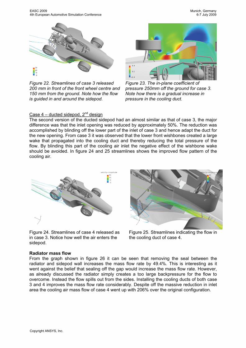
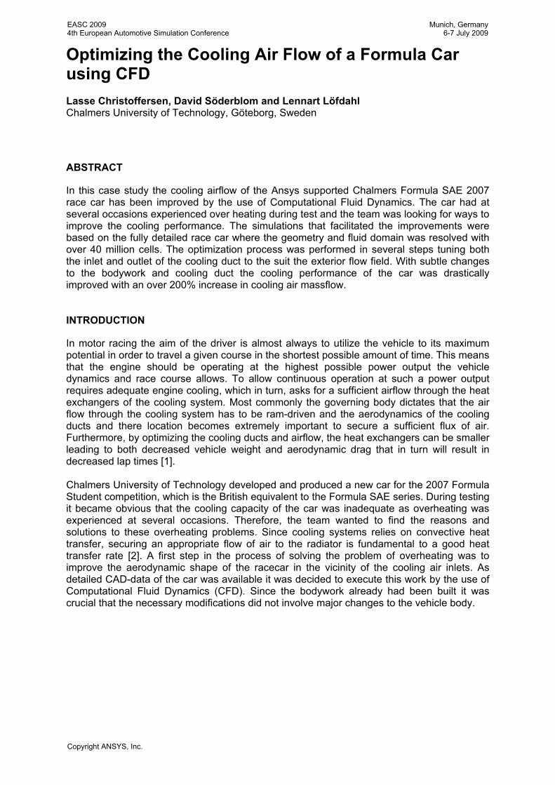
Figure 22. Streamlines of case 3 released 200 mm in front of the front wheel centre and 150 mm from the ground. Note how the flow is guided in and around the sidepod.
Figure 23. The in-plane coefficient of pressure 250mm off the ground for case 3. Note how there is a gradual increase in pressure in the cooling duct.
Case 4 – ducted sidepod, 2nd design The second version of the ducted sidepod had an almost similar as that of case 3, the major difference was that the inlet opening was reduced by approximately 50%. The reduction was accomplished by blinding off the lower part of the inlet of case 3 and hence adapt the duct for the new opening. From case 3 it was observed that the lower front wishbones created a large wake that propagated into the cooling duct and thereby reducing the total pressure of the flow. By blinding this part of the cooling air inlet the negative effect of the wishbone wake should be avoided. In figure 24 and 25 streamlines shows the improved flow pattern of the cooling air.
Figure 24. Streamlines of case 4 released as in case 3. Notice how well the air enters the sidepod.
Figure 25. Streamlines indicating the flow in the cooling duct of case 4.
Radiator mass flow From the graph shown in figure 26 it can be seen that removing the seal between the radiator and sidepod wall increases the mass flow rate by 49.4%. This is interesting as it went against the belief that sealing off the gap would increase the mass flow rate. However, as already discussed the radiator simply creates a too large backpressure for the flow to overcome. Instead the flow spills out from the sides. Installing the cooling ducts of both case 3 and 4 improves the mass flow rate considerably. Despite off the massive reduction in inlet area the cooling air mass flow of case 4 went up with 206% over the original configuration.
EASC 20094th European Automotive Simulation Conference
Munich, Germany6-7 July 2009
Copyright ANSYS, Inc.

Mass flow rate
0
0.05
0.1
0.15
0.2
0.25
[kg/
s]
Baseline
Unsealed
Ducted-case 3
Ducted-case 4
Figure 26. The mass flow rate of the four cases.
Drag and Lift Forces It is interesting to note that the cooling duct of case 3 has a positive effect on both the mass flow rate but also on the drag whereas the duct of case 4 only reduces drag slightly. As can be seen in figure 27 the cooling duct of case 3 decreases the drag by 8.7% or 51 drag counts over the baseline. It is, however interesting to note that the largest drag reduction come from removing the sealing in case 2. The drag reduction is close to 10% or 56 drag counts. This reduction happens as the flow passes around the sides of the radiator and is injected into the wake as previously mentioned.
Drag
0.000
0.100
0.200
0.300
0.400
0.500
0.600
0.700
Cd
Baseline
Unsealed
Ducted-case 3
Ducted-case 4
Lift
0.000
0.020
0.040
0.060
0.080
0.100
0.120
0.140
0.160
Cl
Baseline
UnsealedDucted-case 3
Ducted-case 4
Figure 27. The coefficient of drag for the four cases.
Figure 28. The coefficient of lift for the four cases.
For the coefficient of lift, illustrated in figure 28, it is at first noteworthy that the car produces positive lift despite that it is a racecar. Next; it is shown that when the seal is removed the lift decreases compared to case 1 and furthermore the lift distribution becomes more balanced with a front lift reduction from CLF = 0.199 to 0.101 and rear lift increase from CLR = -0.049 to -0.016. For case 3 and 4 the lift also decreases over the baseline, however, for both cases the front to rear lift distribution becomes more unbalanced. CONCLUSION
In this study it has been shown that ducting of cooling air flow can improve the mass flow rate through the radiator significantly. With the final design iteration of the cooling duct used in this case study the cooling air mass flow rate was increased by 206%.
EASC 20094th European Automotive Simulation Conference
Munich, Germany6-7 July 2009
Copyright ANSYS, Inc.

In order to solve the cooling problems it was recommended to the team to install the duct geometry of case 4 since this configuration offers the highest cooling air flux to drag ratio of the tested configurations. REFERENCES
[1] Agathangelou, A., Gascoyne, M., Aerodynamic Design Considerations of a Formula 1 Racing Car, SAE 980399, 1998.
[2] Incropera, F. P. “Introduction to heat transfer” 5th edition, Wiley 2007. [3] 2007 Formula SAE Rules, Society of Automotive Engineers, 2006. [4] Stone, R. Introduction to Internal Combustion Engines 3rd Edition, McMillan Press
LTD 1999, ISBN 0-333-74013-0. [5] Kuppan, T. Heat Exchanger Design Handbook, Marcel Dekker Inc, 2000, ISBN: 0-
8247-9787-6. [6] Shah, R. K., Sekulić, D. P., Fundamentals of Heat Exchanger Design, John Wiley &
Sons Inc. 2003, ISBN: 0-471-32171-0. [7] FLUENT 6.3 User’s Guide, Fluent Inc. 2006-09-20 [8] Kays, W.M. and London, L.A. Compact Heat Exchangers. McGraw-Hill Book
Company, 3rd edition, 1984. [9] Prior, B. J., Hall, C. N. Subsonic Wind-Tunnel Tests of Various Forms of Air Intake
Installed in a Fighter Type Aircraft, Aeronautical Research Council Reports and Memoranda No. 3134, September 1957.
[10] Harris, T. A., Recant, I, G, Investigation in the 7- by 10-Foot Wind Tunnel of Ducts for Cooling Radiators within an Airplane Wing, N.A.C.A. Report no. 743.
[11] Rivers, D. A., Poulter, J.E., and Lamont, P.J., Aerodynamics of Inclined Radiators on Grand Prix Cars, Royal Aeronautical Society, 1994.
[12] Elofsson, P, Bannister, M. “Drag Reduction Mechanisms Due to Moving Ground and Wheel Rotation in Passenger Cars”, SAE 2002-01-0531, 2002.
[13] Wiedemann, J. “The Influence of Ground Simulation and Wheel Rotation on Aerodynamic Drag Optimization – Potential for Reducing Fuel Consumption”, SAE 960672, 1996.
[14] Wäschle, A. “The Influence of Rotating Wheels on Vehicle Aerodynamics – Numerical and Experimental Investigations”, SAE 2007-01-0107, 2007.
[15] Mlinaric, P., “Investigation of the Influence of Tyre Deformation and Tyre Contact Patch on CFD Predictions of Aerodynamic Forces on a Passenger Car”. M.Sc. Thesis, Chalmers University of Technology, 2007.
[16] Versteeg, H. K. and Malalasekera, W., An Introduction to Computational Fluid Dynamics, Pearson 1995.
[17] Wolf, T. “Minimising the Cooling System Drag for the New Porsche 911 Carrera”, Conference Proceedings 5th MIRA Vehicle Aerodynamics Conference, 2004.
[18] Katz, J., Race Car Aerodynamics, Robert Bentley, 1995.
EASC 20094th European Automotive Simulation Conference
Munich, Germany6-7 July 2009
Copyright ANSYS, Inc.