Optimizing the Configuration and Control of a Novel Human...
8
Optimizing the Configuration and Control of a Novel Human-Powered Energy Harvesting System Vishwa Goudar * , Zhi Ren † , Paul Brochu † , Qibing Pei † and Miodrag Potkonjak * * Computer Science Department, University of California, Los Angeles † Department of Material Science and Engineering, University of California, Los Angeles Abstract—As sensor equipped wearable systems enter the mainstream, system longevity and power-efficiency issues hamper large scale and long-term deployment, despite substantial fore- seeable benefits. As power and energy efficient design, sampling, processing and communication techniques emerge to counter these issues, researchers are beginning to look on wearable energy harvesting systems as an effective counterpart solution. In this paper, we propose a novel harvesting technology to inconspicu- ously transduce mechanical energy from human foot-strikes and power low-power wearable systems in a self-sustaining manner. Dielectric Elastomers (DEs) are high-energy density electrostatic transducers that can transduce significant levels of energy from a user while appearing near-transparent to her, if configured and controlled properly. Towards this end, we propose DE-based harvester configuration that capitalizes on properties of human gait to enhance transduction efficiency, and further leverage these properties in an adaptive control algorithm to optimize the net energy produced by the system. We evaluate system performance from detailed analytical and empirical models of DE transduction behavior, and apply our control algorithm to the modeled DEs under experimentally collected foot pressure datasets from multiple subjects. Our evaluations show that the proposed system can achieve up to 120mJ per foot-strike, enough to power a variety of low-power wearable devices and systems. I. I NTRODUCTION As Wireless Sensor Network (WSN) systems and tech- niques mature and standardize, sensor integrated wearable systems are opening up new avenues in several fields, spanning medicine, environmental monitoring, participatory sensing, human-computer interaction and entertainment. However, their energy demands continue to limit operating lifetimes and sustain maintenance overhead, especially in the mobile context, as battery energy densities evolve at a significantly lower pace [1]. To alleviate this problem, several optimizations have been offered for wearable system design spanning energy-efficient wearable node configuration [2], communication power opti- mization [3], energy-efficient compressed sensing [4], power- efficient context-aware sensor subset selection [5] and plug- and-play systems that support heterogeneous harvesters [6], to name a few. In the context of low-power wearable systems that involve human locomotion, we propose the use of a leading- edge energy harvester technology to scavenge the energy produced by a user’s foot strikes and drive a target wearable system in a self-sustaining manner. Foot strikes have been estimated to yield significant amounts of energy - a 154-pound person can produce upwards of 7W per foot strike [1]. However, the portion of this that can be scavenged is limited by two factors. First, current energy transduction technologies are characterized by energy densities that are insufficient to capture such quantities of energy. Second, state-of-the-art transducer configurations are unable to transduce significant proportions of human energy output without causing discomfort to the user. For example, a hydraulic-amplified piezo-electric based foot-strike energy harvesting system was proposed in [7], capable of producing 675mW per foot-strike while adding significant heft to the shoe, thereby altering the user’s gait. In contrast, the authors of [8] proposed a piezo-electric based foot-strike energy har- vesting system that interfered minimally with the user’s gait and was capable of producing 10-20mW. Recently, a new class of harvesters have emerged with the promise of superior transduction ability and minimal impact on user comfort. Dielectric Elastomers (DEs) are high energy- density rubber-like materials that possess the ability to behave as energy generators, actuators and sensors. Their ability to yield 5 to 40 times the energy density of piezoelectrics [9] makes them more effective transducers. Their soft rubber-like nature further enables near-transparency of the harvesting sub- system to the user. However, while competing technologies transduce ambient energy by exploiting underlying physical phenomena (e.g. seebeck, photovoltaic and piezoelectric ef- fects), DEs transduce mechanical energy based on an electro- static principle. Hence, their configuration and control is key to the levels of energy that they may harvest. In this paper, we propose a DE harvester array configura- tion for improved transduction efficiency of the mechanical energy from foot pressure. We leverage the users plantar pressure profile to control the design of individual transducers in the array, such that the energy yield is more uniformly high across the foot despite spatial variations in the pressure profile. High efficiency is also achieved via direct transduction of input mechanical energy. Finally, its mechanical simplicity keeps system design and maintenance complexity to a minimum. We also propose a novel adaptive closed-loop DE transduction control paradigm that exploits characteristics of the user’s gait to maximize energy output. As electrostatic transducers, DE output is heavily reliant on the control timing during its transduction cycle, which will vary between foot steps owing to variability in the user’s gait. To maximize energy output, we propose an adaptive control algorithm that makes use of fool pressure sensors to predict optimal control timing of each harvester in the array, based on statistical characteristics of the user’s gait. The sensors are sampled to maximize the net energy harvested under sampling power constraints imposed by the power demands of the target system. We validate our proposed transducer configuration by ex- perimentally characterizing and modeling its behavior in detail. The resulting models, in conjunction with our proposed adap- tive control algorithm, are applied to experimentally collected datasets of foot pressure of multiple users to demonstrate that our DE based foot-strike energy harvesting system can yield 978-1-4799-1170-7/13/$31.00 c 2013 IEEE 75
Transcript of Optimizing the Configuration and Control of a Novel Human...

Optimizing the Configuration and Control of a NovelHuman-Powered Energy Harvesting System
Vishwa Goudar∗, Zhi Ren†, Paul Brochu†, Qibing Pei† and Miodrag Potkonjak∗∗Computer Science Department, University of California, Los Angeles
†Department of Material Science and Engineering, University of California, Los Angeles
Abstract—As sensor equipped wearable systems enter themainstream, system longevity and power-efficiency issues hamperlarge scale and long-term deployment, despite substantial fore-seeable benefits. As power and energy efficient design, sampling,processing and communication techniques emerge to counterthese issues, researchers are beginning to look on wearable energyharvesting systems as an effective counterpart solution. In thispaper, we propose a novel harvesting technology to inconspicu-ously transduce mechanical energy from human foot-strikes andpower low-power wearable systems in a self-sustaining manner.Dielectric Elastomers (DEs) are high-energy density electrostatictransducers that can transduce significant levels of energy froma user while appearing near-transparent to her, if configuredand controlled properly. Towards this end, we propose DE-basedharvester configuration that capitalizes on properties of humangait to enhance transduction efficiency, and further leveragethese properties in an adaptive control algorithm to optimizethe net energy produced by the system. We evaluate systemperformance from detailed analytical and empirical models ofDE transduction behavior, and apply our control algorithm tothe modeled DEs under experimentally collected foot pressuredatasets from multiple subjects. Our evaluations show that theproposed system can achieve up to 120mJ per foot-strike, enoughto power a variety of low-power wearable devices and systems.
I. INTRODUCTION
As Wireless Sensor Network (WSN) systems and tech-niques mature and standardize, sensor integrated wearablesystems are opening up new avenues in several fields, spanningmedicine, environmental monitoring, participatory sensing,human-computer interaction and entertainment. However, theirenergy demands continue to limit operating lifetimes andsustain maintenance overhead, especially in the mobile context,as battery energy densities evolve at a significantly lower pace[1]. To alleviate this problem, several optimizations have beenoffered for wearable system design spanning energy-efficientwearable node configuration [2], communication power opti-mization [3], energy-efficient compressed sensing [4], power-efficient context-aware sensor subset selection [5] and plug-and-play systems that support heterogeneous harvesters [6], toname a few. In the context of low-power wearable systems thatinvolve human locomotion, we propose the use of a leading-edge energy harvester technology to scavenge the energyproduced by a user’s foot strikes and drive a target wearablesystem in a self-sustaining manner.
Foot strikes have been estimated to yield significantamounts of energy - a 154-pound person can produce upwardsof 7W per foot strike [1]. However, the portion of this thatcan be scavenged is limited by two factors. First, currentenergy transduction technologies are characterized by energydensities that are insufficient to capture such quantities ofenergy. Second, state-of-the-art transducer configurations are
unable to transduce significant proportions of human energyoutput without causing discomfort to the user. For example,a hydraulic-amplified piezo-electric based foot-strike energyharvesting system was proposed in [7], capable of producing675mW per foot-strike while adding significant heft to theshoe, thereby altering the user’s gait. In contrast, the authorsof [8] proposed a piezo-electric based foot-strike energy har-vesting system that interfered minimally with the user’s gaitand was capable of producing 10-20mW.
Recently, a new class of harvesters have emerged with thepromise of superior transduction ability and minimal impacton user comfort. Dielectric Elastomers (DEs) are high energy-density rubber-like materials that possess the ability to behaveas energy generators, actuators and sensors. Their ability toyield 5 to 40 times the energy density of piezoelectrics [9]makes them more effective transducers. Their soft rubber-likenature further enables near-transparency of the harvesting sub-system to the user. However, while competing technologiestransduce ambient energy by exploiting underlying physicalphenomena (e.g. seebeck, photovoltaic and piezoelectric ef-fects), DEs transduce mechanical energy based on an electro-static principle. Hence, their configuration and control is keyto the levels of energy that they may harvest.
In this paper, we propose a DE harvester array configura-tion for improved transduction efficiency of the mechanicalenergy from foot pressure. We leverage the users plantarpressure profile to control the design of individual transducersin the array, such that the energy yield is more uniformly highacross the foot despite spatial variations in the pressure profile.High efficiency is also achieved via direct transduction of inputmechanical energy. Finally, its mechanical simplicity keepssystem design and maintenance complexity to a minimum.We also propose a novel adaptive closed-loop DE transductioncontrol paradigm that exploits characteristics of the user’sgait to maximize energy output. As electrostatic transducers,DE output is heavily reliant on the control timing during itstransduction cycle, which will vary between foot steps owingto variability in the user’s gait. To maximize energy output,we propose an adaptive control algorithm that makes use offool pressure sensors to predict optimal control timing of eachharvester in the array, based on statistical characteristics ofthe user’s gait. The sensors are sampled to maximize the netenergy harvested under sampling power constraints imposedby the power demands of the target system.
We validate our proposed transducer configuration by ex-perimentally characterizing and modeling its behavior in detail.The resulting models, in conjunction with our proposed adap-tive control algorithm, are applied to experimentally collecteddatasets of foot pressure of multiple users to demonstrate thatour DE based foot-strike energy harvesting system can yield
978-1-4799-1170-7/13/$31.00 c©2013 IEEE 75
upwards of 120mJ per foot-strike, thereby producing enoughenergy to independently power a number of wearable platformswhile the user walks [10], [11], [12].
II. RELATED WORK
Energy harvesting mechanisms may be classified into am-bient radiation, electromagnetic, electrostatic and piezoelec-tric transduction, among others [13]. Whereas solar radiationtransducers offer the most mature and impactful solutions,in the context of mobile devices and wearable systems,their placement requirements and the sporadic availability ofbright light hampers adoptability. Electromagnetic generatorsare most effective and widely popular at the macro-scale,however, they are obtrusive and difficult to miniaturize forthe targeted application domain. Although recently, kineticenergy harvesting with wearable electromagnetic generatorshas been proposed. RF radiation, thermoelectric and con-ventional air-gap electrostatic harvesters are limited in theiroutput capacity (µW to low mW range [1]) with electrostaticharvesters further hindered by their composition of movingparts. Finally, piezo-electrics have higher energy densitiesas compared to electrostatic and electromagnetic transducers,and are also well suited for harvesting the vibrational forcescommonly experienced by human bodies [13]. However, aswe shall see in section III-A, although DEs are electrostatictransducers, their superior material properties distinguish themfrom conventional transducers in this class, making them apromising new candidate.
In the wearable systems and body area networks commu-nity, it is generally agreed upon that energy harvesting poses animportant challenge and opportunity for self-sustenance [14].Aside from body heat transfer via the skin and vibration fromfoot strikes, proposed human-powered transduction alternativesinclude movement of knee joints, inertia from backpacks andchange in blood pressure. A wide array of human motionhas been found suitable for exploitation including cranking,shaking, pumping, pulling as well as the isometric forces ofsqueezing and pushing [1], [13]. However, human gait offerseasy pickings as the most innocuous source of human powerfor transduction, resulting in a long trail of harvesting designsand related patents going back to the mid 1920’s [15]. Twosuch designs were described in section I.
DEs are a relatively new entrant to the class of miniatur-ized generators. An excellent survey of the material proper-ties relevant to its transduction mechanism, various proposedtransducer configurations, capabilities in comparison to othercommon transducers, recent applications, and, operationalboundaries and lifetime issues are detailed in [9]. However,due to its basis in electrostatic transduction, maximizing theoutput of a DE generator, strongly relies on the transducerconfiguration and control methodology. We also note thatDEs require charging at high voltage so they may achievetheir output potential; However self-priming circuits have beenproposed that use an inverse charge pump to convert some ofthe DE voltage boost into charge, incrementally increasing thesource voltage from 10V to the kV range [16]. Finally, adaptivecontrol of DEs has been proposed in the context of actuation[17], however to the best of our knowledge, we are the first topropose an energy-maximizing adaptive control technique forDE generators.
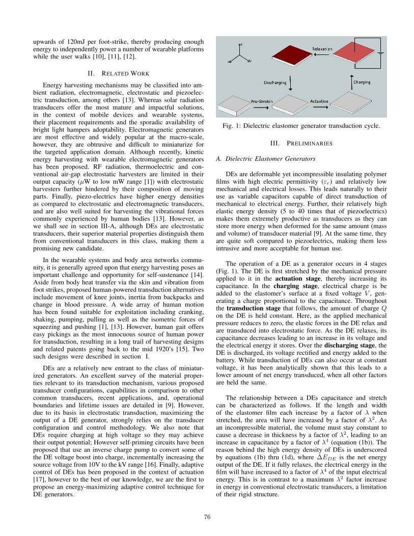
Fig. 1: Dielectric elastomer generator transduction cycle.
III. PRELIMINARIES
A. Dielectric Elastomer Generators
DEs are deformable yet incompressible insulating polymerfilms with high electric permittivity (εr) and relatively lowmechanical and electrical losses. This leads naturally to theiruse as variable capacitors capable of direct transduction ofmechanical to electrical energy. Further, their relatively highelastic energy density (5 to 40 times that of piezoelectrics)makes them extremely productive as transducers as they canstore more energy when deformed for the same amount (massand volume) of transducer material [9]. At the same time, theyare quite soft compared to piezoelectrics, making them lessintrusive and more acceptable for human use.
The operation of a DE as a generator occurs in 4 stages(Fig. 1). The DE is first stretched by the mechanical pressureapplied to it in the actuation stage, thereby increasing itscapacitance. In the charging stage, electrical charge is beadded to the elastomer’s surface at a fixed voltage V , gen-erating a charge proportional to the capacitance. Throughoutthe transduction stage that follows, the amount of charge Qon the DE is held constant. Here, as the applied mechanicalpressure reduces to zero, the elastic forces in the DE relax andare transduced into electrostatic force. As the DE relaxes, itscapacitance decreases leading to an increase in its voltage andthe electrical energy it stores. Over the discharging stage, theDE is discharged, its voltage rectified and energy added to thebattery. While transduction of DEs can also occur at constantvoltage, it has been analytically shown that this leads to alower amount of net energy transduced, when all other factorsare held the same.
The relationship between a DEs capacitance and stretchcan be characterized as follows. If the length and widthof the elastomer film each increase by a factor of λ whenstretched, the area will have increased by a factor of λ2. Asan incompressible material, the volume must stay constant tocause a decrease in thickness by a factor of λ2, leading to anincrease in capacitance by a factor of λ4 (equation (1b)). Thereason behind the high energy density of DEs is underscoredby equations (1b) thru (1d), where ∆EDE is the net energyoutput of the DE. If it fully relaxes, the electrical energy in thefilm will have increased to a factor of λ4 of the input electricalenergy. This is in contrast to a maximum λ2 factor increasein energy in conventional electrostatic transducers, a limitationof their rigid structure.
76
Loading Response Mid-stance Terminal Stance
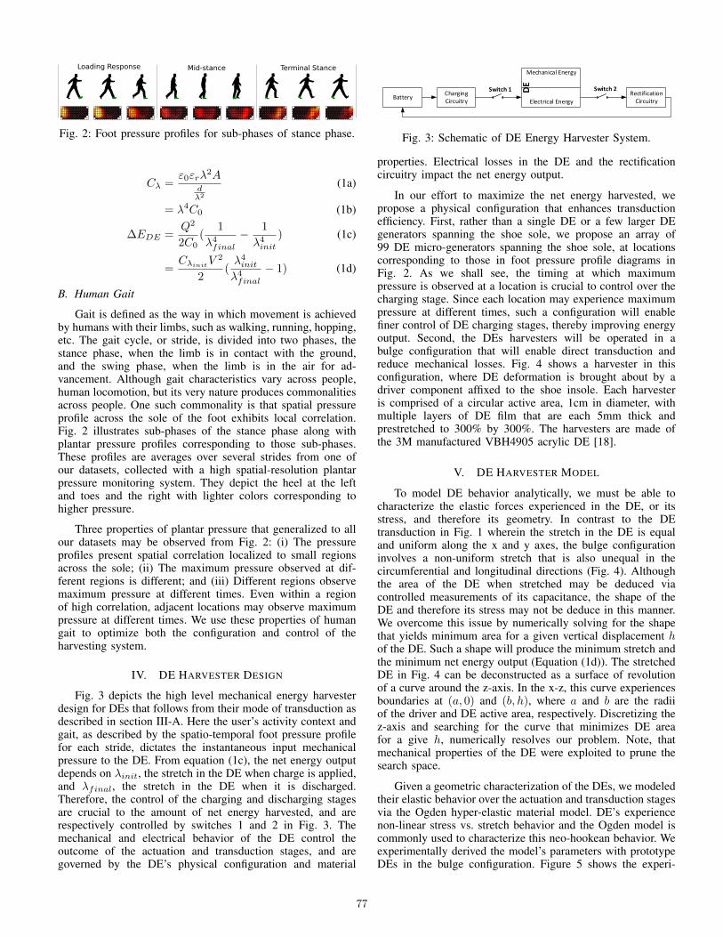
Fig. 2: Foot pressure profiles for sub-phases of stance phase.
Cλ =ε0εrλ
2Adλ2
(1a)
= λ4C0 (1b)
∆EDE =Q2
2C0(
1
λ4final− 1
λ4init) (1c)
=CλinitV
2
2(λ4initλ4final
− 1) (1d)
B. Human Gait
Gait is defined as the way in which movement is achievedby humans with their limbs, such as walking, running, hopping,etc. The gait cycle, or stride, is divided into two phases, thestance phase, when the limb is in contact with the ground,and the swing phase, when the limb is in the air for ad-vancement. Although gait characteristics vary across people,human locomotion, but its very nature produces commonalitiesacross people. One such commonality is that spatial pressureprofile across the sole of the foot exhibits local correlation.Fig. 2 illustrates sub-phases of the stance phase along withplantar pressure profiles corresponding to those sub-phases.These profiles are averages over several strides from one ofour datasets, collected with a high spatial-resolution plantarpressure monitoring system. They depict the heel at the leftand toes and the right with lighter colors corresponding tohigher pressure.
Three properties of plantar pressure that generalized to allour datasets may be observed from Fig. 2: (i) The pressureprofiles present spatial correlation localized to small regionsacross the sole; (ii) The maximum pressure observed at dif-ferent regions is different; and (iii) Different regions observemaximum pressure at different times. Even within a regionof high correlation, adjacent locations may observe maximumpressure at different times. We use these properties of humangait to optimize both the configuration and control of theharvesting system.
IV. DE HARVESTER DESIGN
Fig. 3 depicts the high level mechanical energy harvesterdesign for DEs that follows from their mode of transduction asdescribed in section III-A. Here the user’s activity context andgait, as described by the spatio-temporal foot pressure profilefor each stride, dictates the instantaneous input mechanicalpressure to the DE. From equation (1c), the net energy outputdepends on λinit, the stretch in the DE when charge is applied,and λfinal, the stretch in the DE when it is discharged.Therefore, the control of the charging and discharging stagesare crucial to the amount of net energy harvested, and arerespectively controlled by switches 1 and 2 in Fig. 3. Themechanical and electrical behavior of the DE control theoutcome of the actuation and transduction stages, and aregoverned by the DE’s physical configuration and material
BatteryElectrical Energy
Mechanical Energy
DE
Charging Circuitry
Rectification Circuitry
Switch 1 Switch 2
Fig. 3: Schematic of DE Energy Harvester System.
properties. Electrical losses in the DE and the rectificationcircuitry impact the net energy output.
In our effort to maximize the net energy harvested, wepropose a physical configuration that enhances transductionefficiency. First, rather than a single DE or a few larger DEgenerators spanning the shoe sole, we propose an array of99 DE micro-generators spanning the shoe sole, at locationscorresponding to those in foot pressure profile diagrams inFig. 2. As we shall see, the timing at which maximumpressure is observed at a location is crucial to control over thecharging stage. Since each location may experience maximumpressure at different times, such a configuration will enablefiner control of DE charging stages, thereby improving energyoutput. Second, the DEs harvesters will be operated in abulge configuration that will enable direct transduction andreduce mechanical losses. Fig. 4 shows a harvester in thisconfiguration, where DE deformation is brought about by adriver component affixed to the shoe insole. Each harvesteris comprised of a circular active area, 1cm in diameter, withmultiple layers of DE film that are each 5mm thick andprestretched to 300% by 300%. The harvesters are made ofthe 3M manufactured VBH4905 acrylic DE [18].
V. DE HARVESTER MODEL
To model DE behavior analytically, we must be able tocharacterize the elastic forces experienced in the DE, or itsstress, and therefore its geometry. In contrast to the DEtransduction in Fig. 1 wherein the stretch in the DE is equaland uniform along the x and y axes, the bulge configurationinvolves a non-uniform stretch that is also unequal in thecircumferential and longitudinal directions (Fig. 4). Althoughthe area of the DE when stretched may be deduced viacontrolled measurements of its capacitance, the shape of theDE and therefore its stress may not be deduce in this manner.We overcome this issue by numerically solving for the shapethat yields minimum area for a given vertical displacement hof the DE. Such a shape will produce the minimum stretch andthe minimum net energy output (Equation (1d)). The stretchedDE in Fig. 4 can be deconstructed as a surface of revolutionof a curve around the z-axis. In the x-z, this curve experiencesboundaries at (a, 0) and (b, h), where a and b are the radiiof the driver and DE active area, respectively. Discretizing thez-axis and searching for the curve that minimizes DE areafor a give h, numerically resolves our problem. Note, thatmechanical properties of the DE were exploited to prune thesearch space.
Given a geometric characterization of the DEs, we modeledtheir elastic behavior over the actuation and transduction stagesvia the Ogden hyper-elastic material model. DE’s experiencenon-linear stress vs. stretch behavior and the Ogden model iscommonly used to characterize this neo-hookean behavior. Weexperimentally derived the model’s parameters with prototypeDEs in the bulge configuration. Figure 5 shows the experi-
77

Fig. 4: DE harvester configuration.
mental setup for these stress-stretch measurements - A linearstage (Zaber linear stage model A-LSQ300A-E01) was used tomove a driver affixed load cell (Transducer Techniques MDBSeries) into the active area of the DE prototype that was firmlyfastened in place. The displacement h in the DE film wasmeasured as the displacement in the linear stage, and the inputmechanical pressure measured from the load cell together withthe DE’s geometric characterization were used to arrive at itsstress. A non-linear least squares fit produced the parametersof the Ogden model.
Eharv = LossFactckt(∆EDE − Elosselec) (2)
The net energy harvested is proportional to the differencebetween the net electrical energy generated by the DE andthe electrical losses of the material (equation (2)). Fromequation (1d), whereas λinit is arrived at with the Ogdenmodel solely from the mechanical pressure input at the timeof charging, λfinal depends on the transduction stage thatfollows. To model DE behavior over this stage, we modifiedthe transduction model described in [19] for the geometryinvolved in the bulge configuration. Here, starting from λinit,the net force that leads to a change in stretch is expressedin terms of the balance between the elastic, electrostatic,gravitational and residual mechanical pressure being appliedto the DE. This force balance equation is solved with a Runge-Kutta forth order method to produce the steady state stretchvalue, λfinal. Electrical losses modeled Elosselec include con-duction and dielectric losses in the material, and losses in thecharging circuitry. The net energy harvested also considersDC-DC conversion inefficiencies in the rectification circuit(LossFactckt).
VI. DE HARVESTER ARRAY CONFIGURATION ANDCONTROL OPTIMIZATION
A. Control Parameters
Based on the description of the DE transduction mecha-nism, we identify 4 parameters that can be crucial to the netenergy harvested.
1) Charge Timing: A key observation is that the initialstretch λinit that figures in equation (1d) is a function of thetiming of the applied charge. For example, if DEs at the toesare charged at the beginning of the stance phase when theyexperience no input mechanical pressure, λinit will be closeto 1 regardless of the user-applied pressure that follows duringthe stride. This will result in negative energy harvested due tothe electrical losses. Therefore it is imperative that charge beapplied as close to maximum stretch as possible to maximizethe energy output. Since maximum stretch will be observedat maximum input mechanical pressure (due to monotonicityof the stress-stretch curve), the ability to predict when this
(a) (b)
Fig. 5: (a) Prototype DE harvester, and, (b) Experimental Setupfor DE prototype stress-stretch measurements.
maximum pressure will be observed is key to optimal controlat the charging stage. In the following section, we will explorean adaptive control algorithm that makes use of a few footpressure samples to enable such prediction.
2) Input Pressure: While a higher input mechanical pres-sure will yield a higher stretch and potentially more net energyoutput, this parameter is controlled by users gait over theactuation and transduction stages. However, foot-strikes yielddistinct spatio-temporal properties that may be leveraged toreduce transduction in-efficiencies with an array configurationof DE micro-generators, as discussed in in section IV.
3) Harvester Thickness: A thicker DE film can withstandmuch more pressure without rupture, while a thinner onewill stretch more at comparable applied pressures. Therefore,thinner DE films can harvest more energy at acceptable levelsof applied pressure. Fig. 6 plots the stress-stretch data aswell as the best fit curves for our experimental measurementsfor 3 DE configurations, one with 3 DE layers, a secondwith 6 layers and a third with 9 layers. It is apparent thatthe configuration with more layers must experience morestress to achieve similar levels of strain. Further, differentregions of the foot see different levels of maximum plantarpressure (Fig. 2). To increase the energy yield of low inputpressure regions of the foot, such as the arches, we proposean adaptive harvester placement strategy. Here, the thicknessof a harvester in the array will depend on the amount ofpressure observed over the users gait at its location. Basedon the maximum pressure observed over a training dataset foreach DE location, decisions will be made to fit high pressurelocations with thicker harvesters and low pressure locationswith thinner ones. Specifically, to address harvester lifetimeand user-comfort issues, a location is occupied by the thinnestharvester for which the maximum observed pressure over thetraining dataset produces no more than a vertical displacementh of 9mm, as per the stress-stretch model. This is an acceptablelevel of compression for soft cushioned shoes [20].
4) Applied Voltage: Equation (1d) suggests that higherapplied voltages should yield higher net energy outputs, adinfinitum. However, since the applied voltage is related tothe applied charge, adding too much charge to the elastomerfilm will create large electrostatic forces on it, which willprevent full relaxation of the film at the end of the stancephase. As λfinal is driven away from 1 at higher appliedvoltages, extremely high voltages are undesirable. Figure 7shows the net energy output when a harvester is exposed to
78
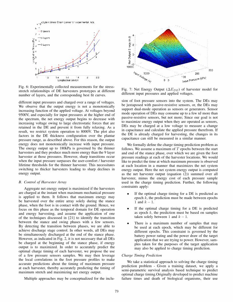
Fig. 6: Experimentally collected measurements for the stress-stretch relationships of DE harvesters prototypes at differentnumber of layers, and the corresponding best fit curves.
different input pressures and charged over a range of voltages.We observe that the output energy is not a monotonicallyincreasing function of the applied voltage. At voltages beyond9500V, and especially for input pressures at the higher end ofthe spectrum, the net energy output begins to decrease withincreasing voltage owing to large electrostatic forces that areretained in the DE and prevent it from fully relaxing. As aresult, we restrict system operation to 8000V. The plot alsofactors in the DE thickness configuration over the plantarpressure range, as described above. For this reason, the outputenergy does not monotonically increase with input pressure.The energy output up to 180kPa is governed by the thinnerharvesters and they produce much more energy than the 9 layerharvester at those pressures. However, sharp transitions occurwhen the input pressure surpasses the user-comfort / harvesterlifetime thresholds for the thinner harvester. This necessitatesswitching to thicker harvesters leading to sharp declines inenergy output.
B. Control of Harvester Array
Aggregate net energy output is maximized if the harvestersare charged at the instant when maximum mechanical pressureis applied to them. It follows that maximum energy maybe harvested over the entire array solely during the stancephase, when the foot is in contact with the ground. Hence, wefocus on this phase as the temporal domain for DE operationand energy harvesting, and assume the application of oneof the techniques discussed in [21] to identify the transitionbetween the stance and swing phases with a few sensors.By detecting the transition between phases, we are able toachieve discharge stage control. In other words, all DEs maybe simultaneously discharged at the end of the stance phase.However, as indicated in Fig. 2, it is not necessary that all DEsbe charged at the beginning of the stance phase, if energyoutput is to maximized. In order to accurately predict theoptimal charge timing of each harvester, we propose the useof a few pressure sensors samples. We may then leveragethe local correlations in the foot pressure profiles to makeaccurate predictions about the timing of maximum pressureat each harvester, thereby accurately predicting the timing ofmaximum stretch and maximizing net energy output.
Multiple approaches may be conceptualized for the inclu-
Fig. 7: Net Energy Output (∆EDE) of harvester model fordifferent input pressures and applied voltages.
sion of foot pressure sensors into the system. The DEs maybe juxtaposed with passive-resistive sensors, or, the DEs maysupport dual-mode operation as sensors or generators. Sensormode operation of DEs may consume up to a few nJ more thanpassive-resistive sensors, but not more; Since our goal is notto maximize energy output when they are operated as sensors,DEs may be charged at a low voltage to measure a changein capacitance and calculate the applied pressure therefrom. Ifthe DE is already charged for harvesting, the changes in itscapacitance can still be measured in a similar manner.
We formally define the charge timing prediction problem asfollows. We assume a maximum of T epochs between the startand end of the stance phase, over which we are given the footpressure readings at each of the harvester locations. We wouldlike to predict the time at which maximum pressure is observedat each location in a manner that maximizes the net systemenergy output. Here the net system energy output is computedas the net harvester output (equation (2)) summed over allharvester, minus the energy cost of each pressure sampleused in the charge timing prediction. Further, the followingconstraints apply:
• If the optimal charge timing for a DE is predicted asepoch k, the prediction must be made between epochs1 and k − 1.
• If the optimal charge timing for a DE is predictedas epoch k, the prediction must be based on samplestaken solely between 1 and k − 1.
• There is a maximum number of samples that maybe used at each epoch, which may be different fordifferent epochs. This constraint is governed by thebattery power rating and the power draw of the targetapplication that we are trying to power. However, sam-ples taken for the purposes of the target applicationmay also be applied to charge timing prediction.
Charge Timing Prediction
We take a statistical approach to solving the charge timingprediction problem - Given a training dataset, we apply asemi-parametric survival analysis based technique to predictoptimal charge timing.Originally developed to predict machinefailure times and death of biological organisms, their use
79

Algorithm 1 ctPred: Optimal Charge Timing PredictionInput: k value of next epoch, sj value of sample j,βj the cox coefficient for samples sj , and F0 thenon-parametric estimates of the cumulative hazard func-tion
1: F ← F0e
∑jβjsj
2: Sr ← e−F
3: for i← k to end of stance phase - 1 do4: Pr(i)← Sr(i)− Sr(i+ 1)5: end for6: Ep← epoch at which Pr(i) is maximum7: if Ep = k then8: Charge Harvester at epoch k9: end if
has expanded to several applications requiring time-to-eventprediction. Based on a training dataset, the survival rate S(t)of a harvester is the probability that its optimal charge timinghasn’t yet occurred. The hazard rate f(t) is the conditionalprobability that the optimal charge timing will occur at epoch t,under the condition that it hasn’t occurred yet. The cumulativehazard rate F (t) is the sum of the hazard rates less than orequal to t. And from equation (3a) it follows that it is thenegative log of the survival rate.
f(t) =S(t)− S(t+ ∆t)
∆tS(t)(3a)
F (t) =
t∑t′=0
f(t) (3b)
= −log(S(t)) (3c)
Cox regression, coxReg() is a semi-parametric survivalregression technique. Given a dataset of optimal charge timingfor a DE over several steps, and a set of covariates x1 thruxn, that signify a subset of samples, the algorithm constructsa cumulative hazard rate function based on a non-parametricbaseline estimate of the function, and multiplicative effectsparameter composed of a linear combination of the samplesxi. The coefficients βi are derived as maximum-likelihoodestimates for on the training set.
F (t) = F0(t)eβ1x1+β2x2+...+βnxn (4)
Algorithm 1 outlines the procedure used to decide whethera DE should be charged at the following epoch based onthe samples available so far. The algorithm is called foreach uncharged harvester and at each epoch, and is providedthe samples available thus far, along with the correspondingcox regression parameters. With these inputs, the algorithmcomputes the cumulative hazard function for the followingepoch k and converts the function to the corresponding survivalrate function Sr. While the survival rate function tells us theprobability that the optimal charge timing won’t have occurredat each future epoch, lines 3 thru 5 of the algorithm convertthis to the probability that optimal charge timing will occur ateach future epoch. If the highest probability co-incides withthe following epoch, a decision is taken to charge the DE. Thealgorithm waits until just before the optimal charge timingis expected for two reasons. First, this provides additionalinformation that is likely to lead to a better decision. Second,
Algorithm 2 Optimal Predictive Sample Subset SelectionInput: S0, set of available samples, C, set of energy costs ofsamples in S0, and H , set of harvestersOutput: S, selected predictive sample subset
1: S ← NULL2: loop3: spj ← −Cj ∀ sj ∈ S0
4: for all hi ∈ H , sj ∈ S0, k > t(sj) do5: CP ← coxReg(hi, k, (S ∪ sj))6: if AIC fails on (S ∪ sj) then7: Continue8: end if9: ∆E ← avgImp(hi, S, ctPred(hi, k, (S ∪ sj), CP ))
10: if ∆E > 0 then11: spj ← spj + ∆E12: end if13: end for14: sk ← {sj | spj ≥ spk∀sk ∈ S0}15: if spk ≤ 0 then16: return S17: end if18: S ← S ∪ sk19: S0 ← S0\ (sk∪ (sj | sj violates power constraints))20: if S0 is empty then21: return S22: end if23: end loop
we observed that with fewer epochs remaining until the endof the stance phase, it increases the kurtosis of the optimalcharge timing probability density function thereby improvingour expectation.
C. Offline Optimization
Given our use of the survival analysis technique, the chargetiming prediction problem stated in section VI-B turns into asample selection problem that offers the best predictions whileabiding by the constraints therein. We solve the problem withthe stepwise-regression based optimization in algorithm 2. Inthe absence of samples, each harvester’s timing is predictedfrom its baseline hazard functions. Else, each sample, sj , isevaluated via avgImp() that measures the improvement sjaffords to the prediction of harvester hi (line 9), averagedover training steps. This improvement contributes to sj’sprofit spj (lines 10 thru 12). The prediction’s improvementis measured in terms of the increase in energy output of hidue to the addition of sj into its predictive sample subsetfor epoch k. At each iteration, the most profitable sample isselected into the predictive subset (lines 14 thru 17). Note,that if a sample is available freely, due to its necessity inthe target application, its cost Cj is 0. Otherwise, its costcorresponds to the energy expended in acquiring the sample.Power constraints are observed by line 19, and overfitting isprevented by applying the Akaike Information Criterion (AIC)to evaluate goodness of fit before accepting a sample into aharvester’s predictive subset for an epoch (lines 6 thru 8). Forthe sake of brevity, we have implicitly assumed that lines 11and 18 include mechanisms to denote which harvester andepoch each included sample will be used to predict.
80

Fig. 8: The maximum energy harvestable from the left andright feet of a user in the plantar pressure dataset, averagedover strides, with uniformly thick DEs across the array (right),and those with location sensitive DE thickness (left)
VII. PERFORMANCE EVALUATION
We evaluate the system performance with experimentallycollected foot plantar pressure datasets by Hermes [10] from3 users. Hermes is a wireless low-power human balancemonitoring system, which measures foot plantar pressure viaa multi-sensory array comprised of ninety-nine passive resis-tive pressure sensors. While Hermes was used to collect thedatasets we use in our evaluation, the goal of our evaluation is,in part, to assess whether the designed system can be appliedto power Hermes in a self-sustaining manner as it monitor’sthe wearers gait. Two of the datasets correspond to the gaits oflighter individuals, one male and one female. The third datasetcorresponds to a heavier male individual. Each of the datasetsoffer several steps worth of data at each of the ninety-nineharvester locations. This allows us to derive performance at allharvesters and apply the predictive sample subset selection andcontrol algorithms, thereby evaluating the system net energyoutput. We divide each dataset into a training subset comprisedof 80% of the data and a testing subset comprised of the rest.
Figure 8 presents the maximum energy scavengable (withperfect charge timing prediction), averaged over the stridesin the datasets, for both feet of a single user. Here, themaximum achievable output with and without the location-specific thickness configuration are juxtaposed. While theareas that normally produce large amounts of plantar pressureproduce exactly the same amounts of energy, surroundingareas, that were previously anemic in their output begin to lookmore promising. To test the predictive sample subset selectionalgorithm, we leveraged the research in [21] towards power-constrained sub-sampling with Hermes. The authors therein,proposed a semantic accuracy preserving sampling strategythat reduced the energy consumption of Hermes from 72mJ to43mJ per stride, under power constraints of at most 5 sensorssampled at a time. We leverage the output of the algorithmproposed in that work and constrained our algorithm by thosesamples. Additional samples were allowed to be chosen. if apower constraints of 5 samples per epoch permitted this.
Fig. 9: Bar Plots for the prediction accuracy of different sampleselection and optimal charge timing prediction techniques overthe testing subsets of each of our datasets
Table I compares the average aggregate energy output ofour proposed system, under both DE configurations (withand without location-specific thickness), for each of thedatasets. Owing to the superior material properties of DEsand the accuracy of our algorithm, our system outperformsthe piezoelectric-driven system in [1] that produced 20mJ perstride. Also, across our datasets and with both our configura-tions, we are able to satisfy the energy demands of our targetapplications (43mJ). Furthermore, owing to our algorithm’s in-built penalties for overfitting, we observed minimal differencebetween performance over the training and testing subsets forall datasets ( <1%).
We also tested the necessity for a sampling subset selectionalgorithm. In figure 9, we compare the performance over thetesting subset of 3 sampling subset selection techniques: (i)Our proposed technique, (ii) an adaptive system where allavailable samples are provided to the cox-regression algorithm,and, (iii) an algorithm that estimates charge timing of eachharvester as the median epoch, over the training dataset, atwhich its net energy output was maximum. The comparison isshown for all 6 datasets. It is clear that an adaptive system canyield more energy. Furthermore, the prediction accuracy of thesecond technique over the training subset was more than 98%for each of the datasets. However, the accuracy over testingdoes not rise beyond 75%, clearly a case of overfitting.
Another question we sought to answer was whether there
TABLE I: Performance Comparison of Foot Strike EnergyHarvesting Output.
Scavenger Net Energy Net EnergyMechanism Output (mJ) Output (mJ)
- Layers - UniformUser 1, Left 107.1 91.5
User 1, Right 120.5 98.3User 2, Left 86.9 68.0
User 1, Right 81.9 69.5User 3, Left 90.0 71.8
User 3, Right 80.8 71.2
81

Fig. 10: Performance of our propose predictive sample subsetselection algorithm under different power constraints
was something inherent in the samples afforded by the algo-rithm in [21] that yielded such high outputs. As it turns out,the answer is yes. Figure 10 shows the prediction accuracyfrom using between 1 and 5 samples per epoch restricted tothe samples produced by [21]. It also shows the predictionaccuracy when the samples are randomly chosen at each epoch.Note that the sample subset selection algorithm was run onthe chosen samples for all cases. Both curves correspond toaverages across 3 of our datasets. The blue curve in figure 10shows that a few random samples per epoch are insufficient inproducing accurate predictions. In these cases, the predictionaccuracy depends mostly on the baseline hazard function as nosamples are chosen into the predictive subset. As the numberof samples per epoch increases beyond 22, the results improveto recognizable levels!
VIII. CONCLUSION
We have experimentally characterized and modeled anovel high energy-density harvesting technology to harvestfoot-strike energy and drive low-power wearable and mobilesystems. We laid out harvester configuration and controltechniques to leverage characteristics of the user’s gait andoptimize energy output. Towards optimized control, we haveproposed a novel and adaptive charge-timing prediction tech-nique and a predictive sample selection algorithm to aid in theadaptive control of the harvesters. Finally, we have validate theperformance of our algorithms over experimentally collecteddatasets of foot pressure produced by different users.
REFERENCES
[1] J. A. Paradiso and T. Starner, “Energy scavenging for mobile andwireless electronics,” IEEE Pervasive Computing, vol. 4, no. 1, pp. 18–27, Jan. 2005.
[2] I. Beretta, F. Rincon, N. Khaled, P. Grassi, V. Rana, D. Atienza,and D. Sciuto, “Model-based design for wireless body sensor networknodes,” in Proc. 13th Latin American Test Workshop (LATW), 2012, pp.1–6.
[3] M. Vallejo, J. Recas, and J. L. Ayala, “Channel analysis and dynamicadaptation for energy-efficient wbsns,” in Proc. 6th International Con-ference on Ubiquitous Computing and Ambient Intelligence. Springer-Verlag, 2012, pp. 42–49.
[4] H. Mamaghanian, N. Khaled, D. Atienza, and P. Vandergheynst,“Compressed sensing for real-time energy-efficient ecg compressionon wireless body sensor nodes,” IEEE Transactions on BiomedicalEngineering, vol. 58, no. 9, pp. 2456–2466, 2011.
[5] P. Zappi, D. Roggen, E. Farella, G. Troster, and L. Benini, “Network-level power-performance trade-off in wearable activity recognition: Adynamic sensor selection approach,” ACM Trans. Embed. Comput. Syst.,vol. 11, no. 3, pp. 68:1–68:30, Sep. 2012.
[6] D. Porcarelli, D. Brunelli, M. Magno, and L. Benini, “A multi-harvesterarchitecture with hybrid storage devices and smart capabilities for lowpower systems,” in Proc. Intl. Symp. on Power Electronics, ElectricalDrives, Automation and Motion (SPEEDAM), 2012, pp. 946–951.
[7] J. F. Antaki, G. E. Bertocci, E. C. Green, A. Nadeem, T. Rintoul, R. L.Kormos, and B. P. Griffith, “A gait-powered autologous battery chargingsystem for artificial organs.” Journal of American Society for ArtificialInternal Organs, vol. 41, no. 3, 1995.
[8] N. S. Shenck and J. A. Paradiso, “Energy scavenging with shoe-mounted piezoelectrics,” IEEE Micro, vol. 21, no. 3, pp. 30–42, May2001.
[9] R. D. Kornbluh, R. Pelrine, H. Prahlad, A. Wong-Foy, B. McCoy,S. Kim, J. Eckerle, and T. Low, “From boots to buoys: promises andchallenges of dielectric elastomer energy harvesting,” Polymer, vol.7976, no. 1, pp. 797 605–797 605–19, 2011.
[10] H. Noshadi, S. Ahmadian, H. Hagopian, J. Woodbridge, F. Dabiri,N. Amini, M. Sarrafzadeh, and N. Terrafranca, “HERMES - mobilebalance and instability assessment system,” in Proc. BIOSIGNALS,2010, pp. 264–270.
[11] T. Choudhury, G. Borriello, S. Consolvo, D. Haehnel, B. Harrison,B. Hemingway, J. Hightower, P. Klasnja, K. Koscher, A. Lamarca,J. Lester, J. Landay, L. Legrand, A. Rahimi, A. Rea, and D. Wyatt,“The Mobile Sensing Platform: An Embedded System for Capturingand Recognizing Human Activities,” IEEE Pervasive Computing, vol. 7,no. 2, pp. 32–41, 2008.
[12] E. Costanza, S. A. Inverso, E. Pavlov, R. Allen, and P. Maes, “eye-q:Eyeglass peripheral display for subtle intimate notifications,” in In Proc.Mobile HCI, year = 2006.
[13] P. Mitcheson, E. Yeatman, G. Rao, A. Holmes, and T. Green, “Energyharvesting from human and machine motion for wireless electronicdevices,” Proceedings of the IEEE, vol. 96, no. 9, pp. 1457 –1486,sept. 2008.
[14] M. Hanson, H. Powell, A. Barth, K. Ringgenberg, B. Calhoun, J. Aylor,and J. Lach, “Body area sensor networks: Challenges and opportunities,”Computer, vol. 42, no. 1, pp. 58 –65, jan. 2009.
[15] J. Paradiso, “Systems for human-powered mobile computing,” in Proc.43rd ACM/IEEE Design Automation Conference, 2006, pp. 645 –650.
[16] T. McKay, B. OBrien, E. Calius, and I. Anderson, “Self-priming di-electric elastomer generators,” Smart Materials and Structures, vol. 19,no. 5, p. 055025, 2010.
[17] T. A. Gisby, E. P. Calius, S. Xie, and I. A. Anderson, “An adaptivecontrol method for dielectric elastomer devices,” in Proc. SPIE Elec-troactive Polymer Actuators and Devices, 2008, pp. 69 271C–69 271C–8.
[18] “3M VHBTM tapes technical data sheet,” 3M, St. Paul, MN.[19] C. Jean-Mistral, S. Basrour, and J.-J. Chaillout, “Modelling of dielectric
polymers for energy scavenging applications,” Smart Materials andStructures, vol. 19, no. 10, p. 105006, 2010.
[20] Optimal performance index system. http://www.opistest.com/. [Online].Available: http://www.opistest.com/
[21] V. Goudar and M. Potkonjak, “Power constrained sensor sample selec-tion for improved form factor and lifetime in localized bans,” in Proc.3rd Conf. on Wireless Health. New York, NY, USA: ACM, 2012.
[22] V. Goudar, Z. Ren, P. Brochu, M. Potkonjak, and Q. Pei, “Drivinglow-power wearable systems with an adaptively-controlled foot-strikescavenging platform,” in 17th International Symposium on WearableComputers (ISWC), 2013.
[23] V. Goudar and M. Potkonjak, “Energy-efficient sampling schedules forbody area networks,” in Proc. IEEE Sensors, 2012, pp. 1–4.
[24] J. Wendt, V. Goudar, H. Noshadi, and M. Potkonjak, “Spatiotemporalassignment of energy harvesters on a self-sustaining medical shoe,” inProc. IEEE Sensors, 2012, pp. 1–4.
82


![Synergies or Trade-Offs? Optimizing a Virtual Urban Region ...€¦ · and Asami[2011, follow-up inHaque and Asami(2014)] that investigate differences in spatial configuration when](https://static.fdocuments.net/doc/165x107/6050aa975ecb864653574da0/synergies-or-trade-offs-optimizing-a-virtual-urban-region-and-asami2011-follow-up.jpg)