Abtech Aluminium Electrical Enclosures Abtech ZAG Junction Boxes
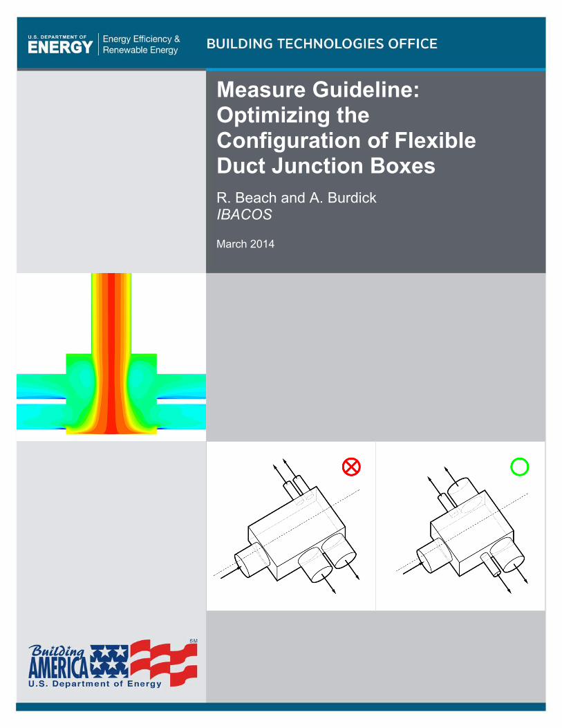
Measure Guideline: Optimizing the Configuration of Flexible Duct Junction Boxes R. Beach and A. Burdick IBACOS
March 2014

NOTICE
This report was prepared as an account of work sponsored by an agency of the United States government. Neither the United States government nor any agency thereof, nor any of their employees, subcontractors, or affiliated partners makes any warranty, express or implied, or assumes any legal liability or responsibility for the accuracy, completeness, or usefulness of any information, apparatus, product, or process disclosed, or represents that its use would not infringe privately owned rights. Reference herein to any specific commercial product, process, or service by trade name, trademark, manufacturer, or otherwise does not necessarily constitute or imply its endorsement, recommendation, or favoring by the United States government or any agency thereof. The views and opinions of authors expressed herein do not necessarily state or reflect those of the United States government or any agency thereof.
Available electronically at http://www.osti.gov/bridge
Available for a processing fee to U.S. Department of Energy and its contractors, in paper, from:
U.S. Department of Energy Office of Scientific and Technical Information
P.O. Box 62 Oak Ridge, TN 37831-0062
phone: 865.576.8401 fax: 865.576.5728
email: mailto:[email protected]
Available for sale to the public, in paper, from: U.S. Department of Commerce
National Technical Information Service 5285 Port Royal Road Springfield, VA 22161 phone: 800.553.6847
fax: 703.605.6900 email: [email protected]
online ordering: http://www.ntis.gov/ordering.htm
Printed on paper containing at least 50% wastepaper, including 20% postconsumer waste
iii
Measure Guideline: Optimizing the Configuration of Flexible Duct Junction Boxes
Prepared for:
The National Renewable Energy Laboratory
On behalf of the U.S. Department of Energy’s Building America Program
Office of Energy Efficiency and Renewable Energy
15013 Denver West Parkway
Golden, CO 80401
NREL Contract No. DE-AC36-08GO28308
Prepared by:
R. Beach and A. Burdick
IBACOS, Inc.
2214 Liberty Avenue
Pittsburgh, Pennsylvania 15222
NREL Technical Monitor: Michael Gestwick
Prepared under Subcontract No. KNDJ-0-40341-03
March 2014

iv
[This page left blank]
v
Contents List of Figures ............................................................................................................................................ vi Definitions .................................................................................................................................................. vii Abstract ..................................................................................................................................................... viii Junction Box Configuration Summary .................................................................................................... ix 1 Introduction ........................................................................................................................................... 1
1.1 Designing with Flexible Duct Junction Boxes.....................................................................1 1.2 Current Design Guidance .....................................................................................................2 1.3 Recommended Junction Box Configurations ......................................................................3 1.4 Risk Factors .........................................................................................................................4 1.5 Summary ..............................................................................................................................4
2 Decision-Making Criteria ..................................................................................................................... 5 2.1 Pressure Drop in an HVAC System .....................................................................................5 2.2 Choice of System Type and Configurations ........................................................................5 2.3 Materials and Labor .............................................................................................................6
3 Technical Description .......................................................................................................................... 7 3.1 General .................................................................................................................................7 3.2 Recommended Configurations.............................................................................................7
4 Measure Implementation ..................................................................................................................... 8 4.1 General Recommendations ..................................................................................................8 4.2 Rectangular Junction Box with Four Outlets .......................................................................8
4.2.1 Size of the Rectangular Junction Box ......................................................................9 4.2.2 Position of the Outlets with a Rectangular Junction Box ........................................9
4.3 Triangular Junction Box with Three Outlets .....................................................................11 4.3.1 Size of the Triangular Junction Box ......................................................................11 4.3.2 Position of the Outlets with a Triangular Junction Box .........................................12
4.4 Metal Wye for Two Outlets ...............................................................................................13 4.5 Mixed Configurations for More Than Four Outlets ..........................................................14
5 Verification Procedures and Tests ................................................................................................... 17 6 Summary ............................................................................................................................................. 17 References ................................................................................................................................................. 19
vi
List of Figures Figure 1. Three optimal junction box configurations, based on number of outlets ............................ 7 Figure 2. Left—An incorrect narrow box width. Right—A correct box width equal to twice the
inlet diameter. ....................................................................................................................................... 9 Figure 3. Left—An incorrect box with an outlet opposite the inlet. Right—A correct box with
outlets on only sides. ........................................................................................................................... 9 Figure 4. Left—An incorrect asymmetrical outlet placement. Right—Correctly placed
symmetrical outlets. ........................................................................................................................... 10 Figure 5. Left and center—Outlets incorrectly placed near the inlet. Right—Outlets correctly
placed one diameter away from the inlet. ........................................................................................ 10 Figure 6. Left—Longer outlets incorrectly placed in front of shorter ones. Right—Longer
outlets correctly placed at the back. ................................................................................................ 11 Figure 7. Left—An unnecessarily large triangular junction box. Center and right—Boxes
exhibiting minimal side lengths. ....................................................................................................... 12 Figure 8. Left—An outlet incorrectly placed at the front of the box, near the inlet. Right—An
outlet positioned correctly at the rear of the box. ........................................................................... 12 Figure 9. Left—The longer outlet incorrectly placed in front of the shorter one. Right—The
longer outlet placed at the back........................................................................................................ 13 Figure 10. Left—A triangular junction box splitting the airflow in two. Right—A more efficient
metal wye fitting for splitting the airflow in two. ............................................................................. 14 Figure 11. A combination of a rectangular box and a triangular box joined with a wye fitting ........ 14 Figure 12. A combination of two triangular boxes joined with a wye fitting ...................................... 15 Figure 13. A combination of a rectangular box and a wye fitting joined with a wye ......................... 15 Figure 14. A combination of a wye fitting and a triangular box joined with a wye ............................ 16
Unless otherwise noted, all figures and photos were created by IBACOS.
vii
Definitions
ACCA Air Conditioning Contractors of America
AHU Air handler unit
ANSI American National Standards Institute
EL Equivalent length
HVAC Heating, ventilation, and air conditioning
TEL Total equivalent length
viii
Abstract
This measure guideline is intended to offer additional recommendations to heating, ventilation, and air conditioning (HVAC) system designers for optimizing flexible duct, constant-volume HVAC systems using junction boxes within Air Conditioning Contractors of America (ACCA) Manual D guidance (Rutkowski 2009).
IBACOS used computational fluid dynamics software to explore and develop guidance to better control the airflow effects of factors that may impact pressure losses within junction boxes among various design configurations (Beach et al. 2013). These recommendations can help to ensure that a system aligns more closely with the design and the occupants’ comfort expectations. The recommendations also will help in developing design strategies that will minimize pressure drop and improve the performance of ducted distribution systems. Specifically, the recommendations described herein show how to configure a rectangular box with four outlets, a triangular box with three outlets, metal wyes with two outlets, and multiple configurations for more than four outlets.
Designers of HVAC systems, contractors who are fabricating junction boxes on site, and anyone using the ACCA Manual D process for sizing duct runs will find this measure guideline invaluable for more accurately minimizing pressure losses when using junction boxes with flexible ducts.
ix
Junction Box Configuration Summary
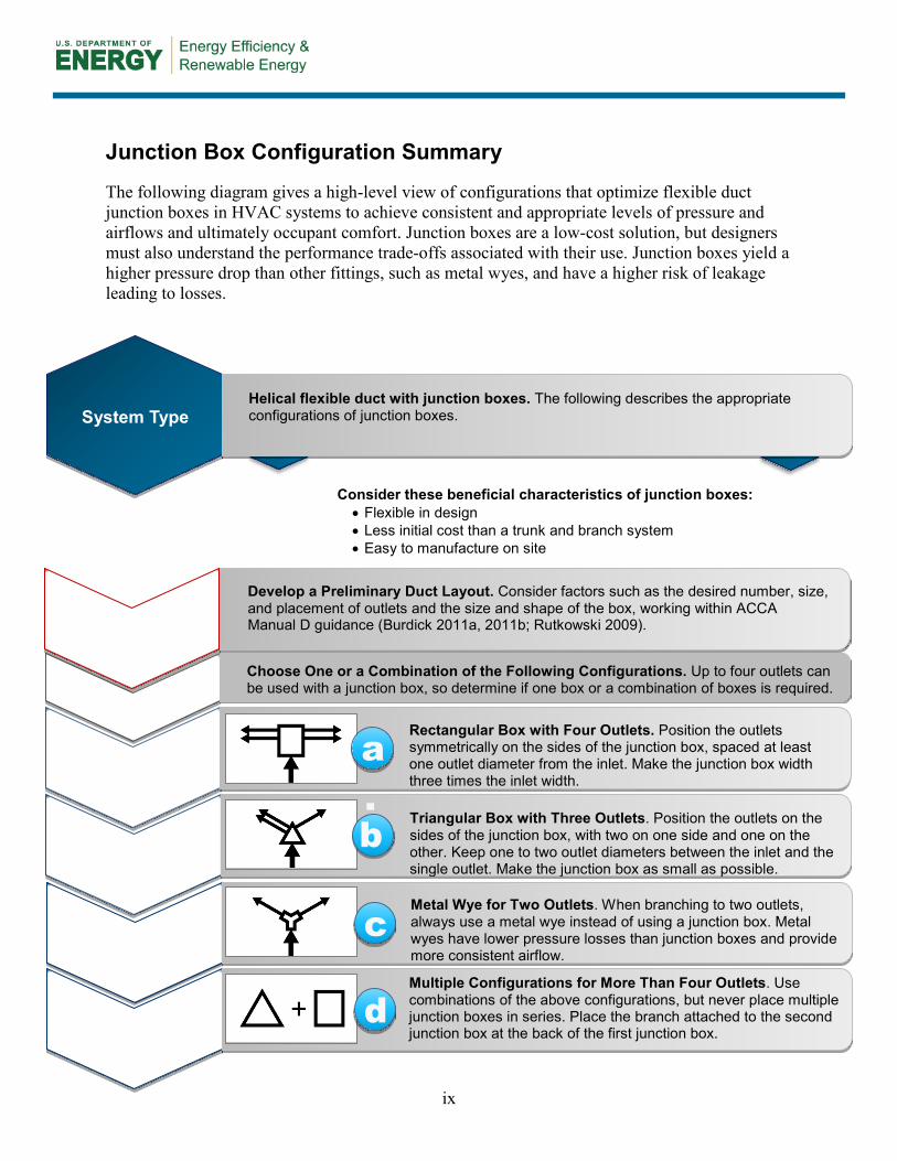
The following diagram gives a high-level view of configurations that optimize flexible duct junction boxes in HVAC systems to achieve consistent and appropriate levels of pressure and airflows and ultimately occupant comfort. Junction boxes are a low-cost solution, but designers must also understand the performance trade-offs associated with their use. Junction boxes yield a higher pressure drop than other fittings, such as metal wyes, and have a higher risk of leakage leading to losses.
ss
System Type Helical flexible duct with junction boxes. The following describes the appropriate configurations of junction boxes.
Choose One or a Combination of the Following Configurations. Up to four outlets can
be used with a junction box, so determine if one box or a combination of boxes is required.
Consider these beneficial characteristics of junction boxes: • Flexible in design • Less initial cost than a trunk and branch system • Easy to manufacture on site
Preliminary Duct Layout
Develop a Preliminary Duct Layout. Consider factors such as the desired number, size, and placement of outlets and the size and shape of the box, working within ACCA Manual D guidance (Burdick 2011a, 2011b; Rutkowski 2009).
Rectangular Box, Four Outlets
Rectangular Box with Four Outlets. Position the outlets symmetrically on the sides of the junction box, spaced at least one outlet diameter from the inlet. Make the junction box width three times the inlet width.
Triangular Box, Three Outlets
Triangular Box with Three Outlets. Position the outlets on the sides of the junction box, with two on one side and one on the other. Keep one to two outlet diameters between the inlet and the single outlet. Make the junction box as small as possible.
a.
Metal Wye, Two Outlets
Metal Wye for Two Outlets. When branching to two outlets, always use a metal wye instead of using a junction box. Metal wyes have lower pressure losses than junction boxes and provide more consistent airflow.
Configurations of
More Than Four Outlets
Multiple Configurations for More Than Four Outlets. Use combinations of the above configurations, but never place multiple junction boxes in series. Place the branch attached to the second junction box at the back of the first junction box.
b
c
d
1
1 Introduction
1.1 Designing with Flexible Duct Junction Boxes Flexible duct junction boxes are commonly used to split airflows in residential heating, ventilation, and air conditioning (HVAC) systems of insulated flexible ducts. Junction boxes typically are made of fiberglass duct board or insulated sheet metal.
IBACOS used computational fluid dynamics software to explore and develop guidance to better control the airflow effects of factors that may impact pressure losses within junction boxes among various design configurations (Beach et al. 2013). As a result, this measure guideline is intended to offer additional recommendations for optimizing flexible duct, constant-volume HVAC systems using junction boxes within ACCA Manual D guidance (Rutkowski 2009). These recommendations, which apply only to supply fittings and not return fittings, can help to ensure that a system aligns more closely with the design and the occupants’ comfort expectations. A discussion of trunk and branch design is beyond the scope of this measure guideline; however, for more system-level duct design information, see Burdick (2011a, 2011b).
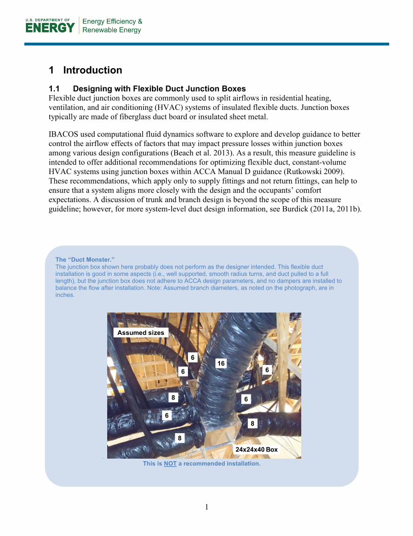
The “Duct Monster.” The junction box shown here probably does not perform as the designer intended. This flexible duct installation is good in some aspects (i.e., well supported, smooth radius turns, and duct pulled to a full length), but the junction box does not adhere to ACCA design parameters, and no dampers are installed to balance the flow after installation. Note: Assumed branch diameters, as noted on the photograph, are in inches.
. This is NOT a recommended installation.
What is WUFI?
166
6
6
6
68
8
8
24x24x40 Box
Assumed sizes
2
Designers of HVAC systems, contractors who are fabricating junction boxes on site, and anyone using the ACCA Manual D process for sizing duct runs will find this measure guideline invaluable for more efficiently minimizing pressure losses when using junction boxes.
Junction boxes are popular and, properly designed, can result in an HVAC system that performs well. However, junction boxes that are poorly designed can have high pressure losses relative to other duct fittings. That is, each junction box creates a higher resistance (e.g., duct friction) that may impede the ability of the air handler unit (AHU) to move the air through the ducts, which in turn may result in occupant comfort complaints. With any duct runout, balancing dampers are needed to adjust the pressure of airflow through the outlets because self-balancing systems are not realistic.
The appeal of junction boxes is that they are compact, are easily and quickly fabricated on site, and have a low material cost. Consequently, junction boxes are frequently used as a “one-size-fits-all” solution and a means to skip the principle of rightsizing of HVAC systems.
1.2 Current Design Guidance ACCA Manual D (Rutkowski 2009) describes a comprehensive set of American National Standards Institute (ANSI) recognized duct sizing principles and calculations for optimizing the design of residential duct systems. ACCA Manual D also provides information about the airflow resistance produced by various types of supply and return fittings as measured in equivalent length (EL). These EL values relate to the amount of pressure the AHU must overcome. They are conditional and typically are accompanied with the respective reference values of velocity and friction rate used to establish the published EL. If the airflow velocity or the friction rate differs from the ACCA reference values, refer to Section A3-3 of ACCA Manual D for adjusting the EL values (Rutkowski 2009, p. 146).
ACCA Manual D guidance allows for variation in the number of outlets, box sizes and shapes, and outlet locations; however, the guidance does not consider all factors that may impact pressure losses across a junction box. The performance of a system with junction boxes may not be acceptable if the standard of care is deficient for any design-installation task or if there is a general deficiency in the overall standard of care for the project. This includes the performance of accurate airway sizing calculations for loads (per ACCA Manual J [Rutkowski 2006]) and equipment selection (per ACCA Manual S [Rutkowski 1995]). Airway sizing calculations depend on the proper use of blower data, component pressure and material friction rate data, and ELs for flexible ducts and fittings.
Equivalent Length. For duct fittings, the airflow resistance produced by a fitting is equivalent to the quantity of feet of straight duct that produces the same resistance (Rutkowski 2009, p. 3).
Friction Rate. The pressure loss between two points in a duct system that are separated by a specific distance. Units are expressed in inches water column per 100 ft (IWC/100).
3
ASHRAE (2012) likewise offers guidance about junction box widths and lengths, pressure losses, and ELs. For example, ASHRAE standards recommend the use of an entrance fitting for stability and that the blower must be moving less than 2,250 cfm.
1.3 Recommended Junction Box Configurations
IBACOS’ recommendations for junction box configurations take into account the pressure variances resulting from factors such as box size and shape, the relative position and symmetry of outlets, and the number of outlets. A series of schematic diagrams and descriptions of supply fittings illustrates the optimized configurations. These configurations also should minimize balancing with the use of dampers.
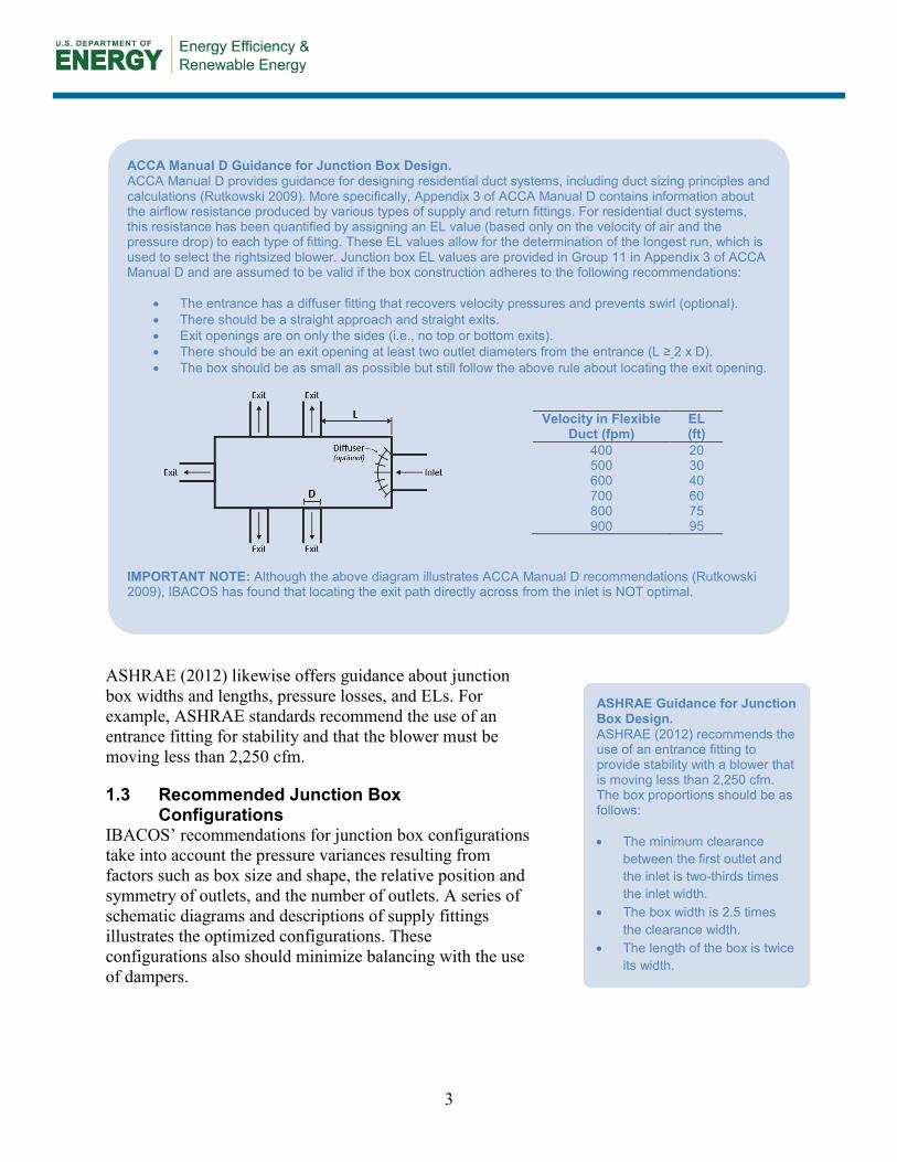
ACCA Manual D Guidance for Junction Box Design. ACCA Manual D provides guidance for designing residential duct systems, including duct sizing principles and calculations (Rutkowski 2009). More specifically, Appendix 3 of ACCA Manual D contains information about the airflow resistance produced by various types of supply and return fittings. For residential duct systems, this resistance has been quantified by assigning an EL value (based only on the velocity of air and the pressure drop) to each type of fitting. These EL values allow for the determination of the longest run, which is used to select the rightsized blower. Junction box EL values are provided in Group 11 in Appendix 3 of ACCA Manual D and are assumed to be valid if the box construction adheres to the following recommendations:
• The entrance has a diffuser fitting that recovers velocity pressures and prevents swirl (optional). • There should be a straight approach and straight exits. • Exit openings are on only the sides (i.e., no top or bottom exits). • There should be an exit opening at least two outlet diameters from the entrance (L ≥ 2 x D). • The box should be as small as possible but still follow the above rule about locating the exit opening.
Velocity in Flexible
Duct (fpm) EL (ft)
400 20 500 30 600 40 700 60 800 75 900 95
IMPORTANT NOTE: Although the above diagram illustrates ACCA Manual D recommendations (Rutkowski 2009), IBACOS has found that locating the exit path directly across from the inlet is NOT optimal.
ASHRAE Guidance for Junction Box Design. ASHRAE (2012) recommends the use of an entrance fitting to provide stability with a blower that is moving less than 2,250 cfm. The box proportions should be as follows: • The minimum clearance
between the first outlet and the inlet is two-thirds times the inlet width.
• The box width is 2.5 times the clearance width.
• The length of the box is twice its width.
4
1.4 Risk Factors If HVAC systems are not sized correctly with appropriate ELs as defined by ACCA Manual D (Rutkowski 2009), additional equipment may be needed to achieve the design goals. This could range from the need for larger equipment and larger duct sizes to a greater number of runs to accommodate increased system airflows, increasing energy use and possibly resulting in occupant comfort complaints. Another concern is the increased noise that results from the higher fan power needed to operate an improperly sized system.
Junction boxes are not necessarily the most energy-efficient option for an HVAC system. It is important to weigh their benefits as a low first-cost and easily installed option versus the benefits of using a trunk and branch system that will provide more certainty to EL values. ACCA Manual D procedures (Rutkowski 2009) process information provided by other calculation tools and information provided by manufacturers’ performance data. This measure guideline assumes that designers have an understanding of load calculations for system and room airflow requirements and duct run attributes such as airflow rate, velocity, and friction rate.
If proper balancing is not accomplished, an HVAC system may not function effectively. Installation and adjustment of balancing dampers are required to effectively deliver air through the duct system.
1.5 Summary A properly designed and rightsized HVAC system results from conservatively estimating pressure drops from junction boxes. Use of the appropriate number of outlets, box sizes and shapes, and outlet locations as described in this measure guideline, in conjunction with ACCA guidance and the selection of appropriate ELs, will help HVAC system designers meet their goals and ensure occupant comfort.
5
2 Decision-Making Criteria
When designing an HVAC system, it is important to rightsize the system for a variety of reasons, ranging from providing occupant comfort to minimizing material costs. Design of the entire HVAC system is beyond the scope of this measure guideline; however, as a system, each portion must have equal consideration in the design process. The use of optimal flexible duct junction box configurations will help to ensure that the entire HVAC system performs closer to design.
2.1 Pressure Drop in an HVAC System When designing an HVAC system, there is pressure loss from each component of the system. Static pressure is defined as the resistance to airflow due to restrictions created by components (e.g., duct friction), whereas available pressure is the difference between the static pressure and the pressure against which the selected equipment can deliver. This value is what is available in the design for duct and supply outlet pressure losses. The sum of all pressure losses is the total pressure drop, which must match the available static pressure of the equipment (Burdick 2011a).
Likewise, the friction rate is the pressure loss between two points in a duct system that are separated by a specific length. That is, it is the average pressure drop per 100 ft of duct in a system. Recommendations on EL values can be found in ACCA Manual D (Rutkowski 2009); however, the proper values must be chosen based on the pressure drop.
The total effective length (TEL) equals the measured length from the farthest supply outlet through the equipment and to the farthest return outlet, plus the ELs of all turns and fittings. Accurate determination of pressure drop and ELs is a key element of HVAC system design.
2.2 Choice of System Type and Configurations A decision must be made about whether to use a trunk and branch duct system or flexible duct junction boxes. Although a trunk and branch system initially may cost more than a system with junction boxes, it can provide greater certainty of EL values and greater efficiency.
At the component level where this measure guideline is focused, fitting selection plays an important role in both cost and EL. Consider, for example, metal wye fittings. ACCA Manual D assigns a 15-ft EL for a metal wye fitting, whereas a junction box receives a significantly higher EL of 95 ft for a reference velocity of 900 ft per minute (fpm). The technical report by Beach et al. (2013) discusses this issue in more detail.
Rightsizing an HVAC System with Load Calculations. Rightsizing involves the selection of appropriate HVAC equipment and designing the corresponding air distribution system to meet the accurate predicted loads of the house and the occupants’ comfort expectations. Systems designed by “rules of thumb” rather than load calculations may not achieve the design targets. Load calculations are dependent on the location, orientation, and construction of the building, as well as the indoor design conditions. It is important to perform accurate load calculations at the start of the design phase and to follow ACCA Manual D recommendations for EL values. Even then, when using flexible duct junction boxes, the EL values must be adjusted with balancing dampers later in the process. For more details on accurately predicting load calculations, see Burdick (2011b) and Rutkowski (2006).
6
On the other hand, junction boxes are flexible and can be quickly fabricated on site, but they add significantly more pressure to systems compared to trunk and branch systems. To account for the increased pressure drop resulting from the use of junction boxes, a designer may need to specify larger duct sizes than those in a trunk and branch system.
Also, junction boxes must be optimally configured to minimize pressure losses and the difficult task of balancing of dampers. Thus, the achievement of consistently even airflows and better air distribution for occupant comfort should be weighed against ease of installation and cost factors.
2.3 Materials and Labor Although pressure losses are high for flexible duct junction boxes relative to other standard duct fittings, they are preferred by contractors because flexible duct junction boxes are compact, are easily and quickly fabricated, and have a low material cost. Installing three or four ducts from one fitting instead of multiple tee or wye fittings reduces the installing contractor’s labor time and corresponding cost. Junction boxes typically are made of insulated sheet metal or fiberglass duct board that can readily be formed into angular shapes. First costs of the fiberglass duct board generally are lower than those of insulated sheet metal, and fiberglass duct board is easier to cut and work with than insulated sheet metal. Potential risks associated with fiberglass duct board include susceptibility to damage and tearing (i.e., fragility) and possible degradation over time, resulting in leakage.
Lightweight plastic duct might seem like a good choice of material because it can allow for a lightweight assembly appropriately sized for low airflows. Plastic duct is smoother and more efficient than wire helix, thereby creating less resistance and friction to airflows. However, current codes do not allow the use of plastic duct in HVAC systems due to potential flammability issues.
The choice of duct material as related to junction boxes must consider the friction factors of the different duct materials because increased friction or duct length add to the total pressure loss. Small junction box sizes are described in this guide to replicate what a production builder would likely build in an HVAC system where the minimal amount of material was used to construct a junction box.
Because flexible duct has a higher friction rate than the smooth inner surface of galvanized steel ductwork, this friction creates a resistance that affects the capacity of flexible ducts to carry air and ultimately lead to occupant comfort in a room. Therefore, the choice of materials greatly impacts the pressure drop as air flows through junction boxes (Burdick 2011a).
Junction boxes can be field fabricated on site from the design-driven dimensions, or they can be built in the shop and then sent to the job site with the installing contractor. In either case, the effort is to make the box as small as possible to conserve material and related costs while maintaining the requisite dimensions. Fabrication on the job site can have the added challenge of maintaining an appropriate work space in which to complete the boxes, whereas shop fabrication can offer a more controlled environment.
7
3 Technical Description
3.1 General This measure guideline offers advanced design recommendations to optimize flexible duct junction box configurations, with a focus on supply outlets. These configurations minimize variations and work hand in hand with the use of ELs chosen from ACCA Manual D (Rutkowski 2009). The benefits of these configurations are that they can minimize balancing and can bring a system closer to the intent of its design. To achieve a TEL for a system, a designer still needs to find the EL for each fitting per ACCA Manual D.
A designer should evaluate whether a trunk and branch system or the use of junction boxes is the best system for a specific project. Although a trunk and branch system can provide more certainty of EL values, junction boxes initially cost less and are easily manufactured on site. When choosing which junction box configuration to use, a designer should consider the size and shape of the box and the number, size, and relative position of the outlets. ACCA Manual D should be consulted for the ELs and values related to air velocity, volumetric flow rate, and friction rate of the ducts.
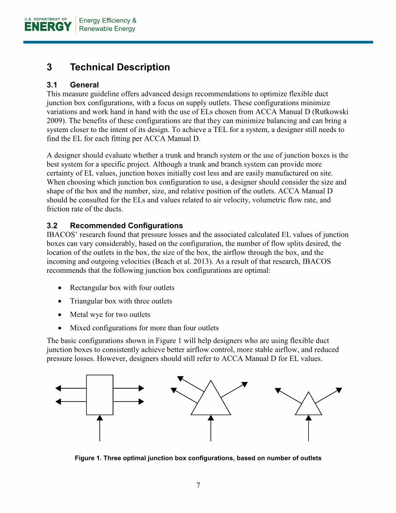
3.2 Recommended Configurations IBACOS’ research found that pressure losses and the associated calculated EL values of junction boxes can vary considerably, based on the configuration, the number of flow splits desired, the location of the outlets in the box, the size of the box, the airflow through the box, and the incoming and outgoing velocities (Beach et al. 2013). As a result of that research, IBACOS recommends that the following junction box configurations are optimal:
• Rectangular box with four outlets
• Triangular box with three outlets
• Metal wye for two outlets
• Mixed configurations for more than four outlets The basic configurations shown in Figure 1 will help designers who are using flexible duct junction boxes to consistently achieve better airflow control, more stable airflow, and reduced pressure losses. However, designers should still refer to ACCA Manual D for EL values.
Figure 1. Three optimal junction box configurations, based on number of outlets
8
4 Measure Implementation
IBACOS found that the junction box layouts shown in Figure 1 are optimal for achieving stable airflows and reduced pressure losses. However, several factors can affect the successful design of these layouts, such as the number, position, and spacing of the outlets and, in some cases, the size of the junction box.
4.1 General Recommendations All junction boxes should be laid out to maximize the geometric symmetry (balanced proportions—both side to side and front to back) and the symmetrical allocation of airflow. A symmetrical layout provides better control of the flow splits and minimizes the need for balancing.
Regardless of the configuration, all duct runs should have balancing dampers as recommended by ACCA Manual D (Rutkowski 2009). Balancing of airflows to the design values is essential for proper system operation.
The choice of junction box shape (i.e., rectangular or triangular) depends on the number of outlets. For the most consistent airflow, a rectangular box can accommodate four outlets, and a triangular box can accommodate three outlets. However, for two outlets, a metal wye is more effective than a junction box.
Any single junction box should have no more than four outlets. If more than four outlets are needed, then use a combination of rectangular or triangular boxes having four or three outlets, respectively, plus a metal wye for two outlets.
Finally, in high friction rate systems such as small-diameter homerun systems, pressure loss at the junction box appears to be a much smaller percentage of the total system pressure. Thus, junction boxes can be reasonable choices for those types of systems.
4.2 Rectangular Junction Box with Four Outlets As stated above, all duct runs used with rectangular junction boxes should have balancing dampers and symmetry in the placement of the outlets. The size of the junction box can also impact the effectiveness of the configuration.
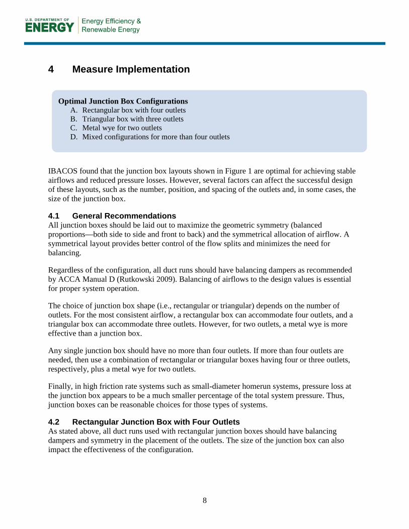
Optimal Junction Box Configurations A. Rectangular box with four outlets B. Triangular box with three outlets C. Metal wye for two outlets D. Mixed configurations for more than four outlets
9
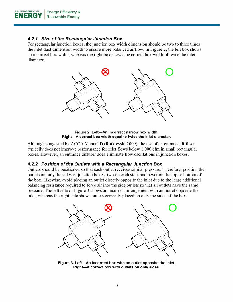
4.2.1 Size of the Rectangular Junction Box For rectangular junction boxes, the junction box width dimension should be two to three times the inlet duct dimension width to ensure more balanced airflow. In Figure 2, the left box shows an incorrect box width, whereas the right box shows the correct box width of twice the inlet diameter.
Figure 2. Left—An incorrect narrow box width. Right—A correct box width equal to twice the inlet diameter.
Although suggested by ACCA Manual D (Rutkowski 2009), the use of an entrance diffuser typically does not improve performance for inlet flows below 1,000 cfm in small rectangular boxes. However, an entrance diffuser does eliminate flow oscillations in junction boxes.
4.2.2 Position of the Outlets with a Rectangular Junction Box Outlets should be positioned so that each outlet receives similar pressure. Therefore, position the outlets on only the sides of junction boxes: two on each side, and never on the top or bottom of the box. Likewise, avoid placing an outlet directly opposite the inlet due to the large additional balancing resistance required to force air into the side outlets so that all outlets have the same pressure. The left side of Figure 3 shows an incorrect arrangement with an outlet opposite the inlet, whereas the right side shows outlets correctly placed on only the sides of the box.
Figure 3. Left—An incorrect box with an outlet opposite the inlet.
Right—A correct box with outlets on only sides.
10
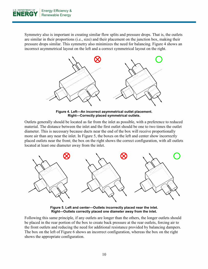
Symmetry also is important in creating similar flow splits and pressure drops. That is, the outlets are similar in their proportions (i.e., size) and their placement on the junction box, making their pressure drops similar. This symmetry also minimizes the need for balancing. Figure 4 shows an incorrect asymmetrical layout on the left and a correct symmetrical layout on the right.
Figure 4. Left—An incorrect asymmetrical outlet placement.
Right—Correctly placed symmetrical outlets.
Outlets generally should be located as far from the inlet as possible, with a preference to reduced material. The distance between the inlet and the first outlet should be one to two times the outlet diameter. This is necessary because ducts near the end of the box will receive proportionally more air than any near the inlet. In Figure 5, the boxes on the left and center show incorrectly placed outlets near the front; the box on the right shows the correct configuration, with all outlets located at least one diameter away from the inlet.
Figure 5. Left and center—Outlets incorrectly placed near the inlet. Right—Outlets correctly placed one diameter away from the inlet.
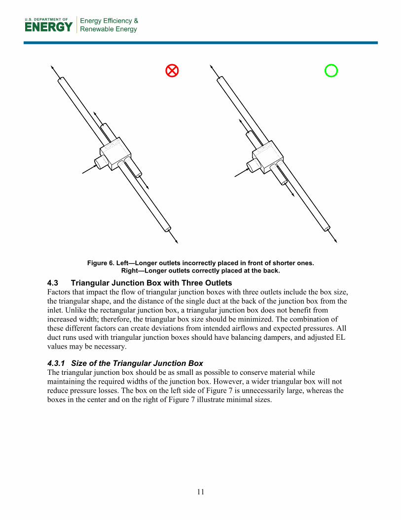
Following this same principle, if any outlets are longer than the others, the longer outlets should be placed in the rear portion of the box to create back pressure at the rear outlets, forcing air to the front outlets and reducing the need for additional resistance provided by balancing dampers. The box on the left of Figure 6 shows an incorrect configuration, whereas the box on the right shows the appropriate configuration.
11
Figure 6. Left—Longer outlets incorrectly placed in front of shorter ones. Right—Longer outlets correctly placed at the back.
4.3 Triangular Junction Box with Three Outlets Factors that impact the flow of triangular junction boxes with three outlets include the box size, the triangular shape, and the distance of the single duct at the back of the junction box from the inlet. Unlike the rectangular junction box, a triangular junction box does not benefit from increased width; therefore, the triangular box size should be minimized. The combination of these different factors can create deviations from intended airflows and expected pressures. All duct runs used with triangular junction boxes should have balancing dampers, and adjusted EL values may be necessary.
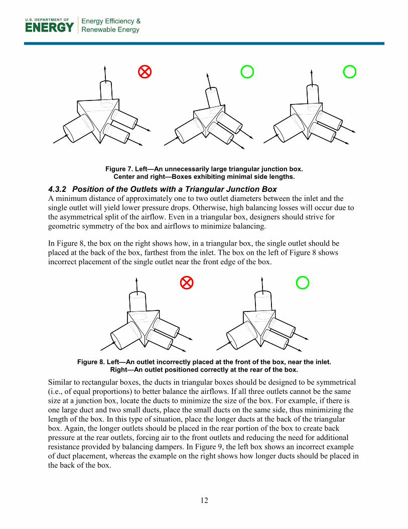
4.3.1 Size of the Triangular Junction Box The triangular junction box should be as small as possible to conserve material while maintaining the required widths of the junction box. However, a wider triangular box will not reduce pressure losses. The box on the left side of Figure 7 is unnecessarily large, whereas the boxes in the center and on the right of Figure 7 illustrate minimal sizes.
12
Figure 7. Left—An unnecessarily large triangular junction box. Center and right—Boxes exhibiting minimal side lengths.
4.3.2 Position of the Outlets with a Triangular Junction Box A minimum distance of approximately one to two outlet diameters between the inlet and the single outlet will yield lower pressure drops. Otherwise, high balancing losses will occur due to the asymmetrical split of the airflow. Even in a triangular box, designers should strive for geometric symmetry of the box and airflows to minimize balancing.
In Figure 8, the box on the right shows how, in a triangular box, the single outlet should be placed at the back of the box, farthest from the inlet. The box on the left of Figure 8 shows incorrect placement of the single outlet near the front edge of the box.
Figure 8. Left—An outlet incorrectly placed at the front of the box, near the inlet.
Right—An outlet positioned correctly at the rear of the box.
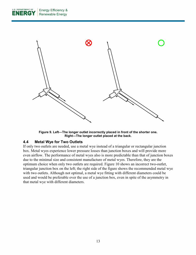
Similar to rectangular boxes, the ducts in triangular boxes should be designed to be symmetrical (i.e., of equal proportions) to better balance the airflows. If all three outlets cannot be the same size at a junction box, locate the ducts to minimize the size of the box. For example, if there is one large duct and two small ducts, place the small ducts on the same side, thus minimizing the length of the box. In this type of situation, place the longer ducts at the back of the triangular box. Again, the longer outlets should be placed in the rear portion of the box to create back pressure at the rear outlets, forcing air to the front outlets and reducing the need for additional resistance provided by balancing dampers. In Figure 9, the left box shows an incorrect example of duct placement, whereas the example on the right shows how longer ducts should be placed in the back of the box.
13
Figure 9. Left—The longer outlet incorrectly placed in front of the shorter one. Right—The longer outlet placed at the back.
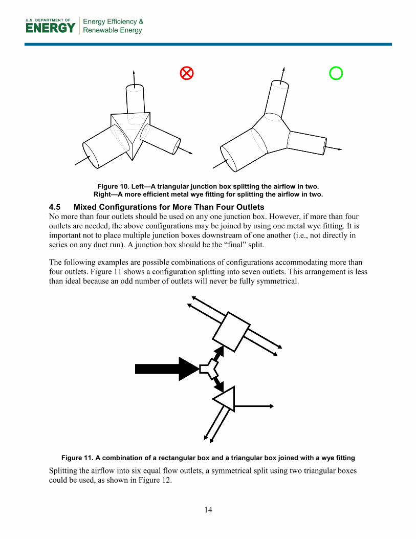
4.4 Metal Wye for Two Outlets If only two outlets are needed, use a metal wye instead of a triangular or rectangular junction box. Metal wyes experience lower pressure losses than junction boxes and will provide more even airflow. The performance of metal wyes also is more predictable than that of junction boxes due to the minimal size and consistent manufacture of metal wyes. Therefore, they are the optimum choice when only two outlets are required. Figure 10 shows an incorrect two-outlet, triangular junction box on the left; the right side of the figure shows the recommended metal wye with two outlets. Although not optimal, a metal wye fitting with different diameters could be used and would be preferable over the use of a junction box, even in spite of the asymmetry in that metal wye with different diameters.
14
Figure 10. Left—A triangular junction box splitting the airflow in two. Right—A more efficient metal wye fitting for splitting the airflow in two.
4.5 Mixed Configurations for More Than Four Outlets No more than four outlets should be used on any one junction box. However, if more than four outlets are needed, the above configurations may be joined by using one metal wye fitting. It is important not to place multiple junction boxes downstream of one another (i.e., not directly in series on any duct run). A junction box should be the “final” split.
The following examples are possible combinations of configurations accommodating more than four outlets. Figure 11 shows a configuration splitting into seven outlets. This arrangement is less than ideal because an odd number of outlets will never be fully symmetrical.
Figure 11. A combination of a rectangular box and a triangular box joined with a wye fitting
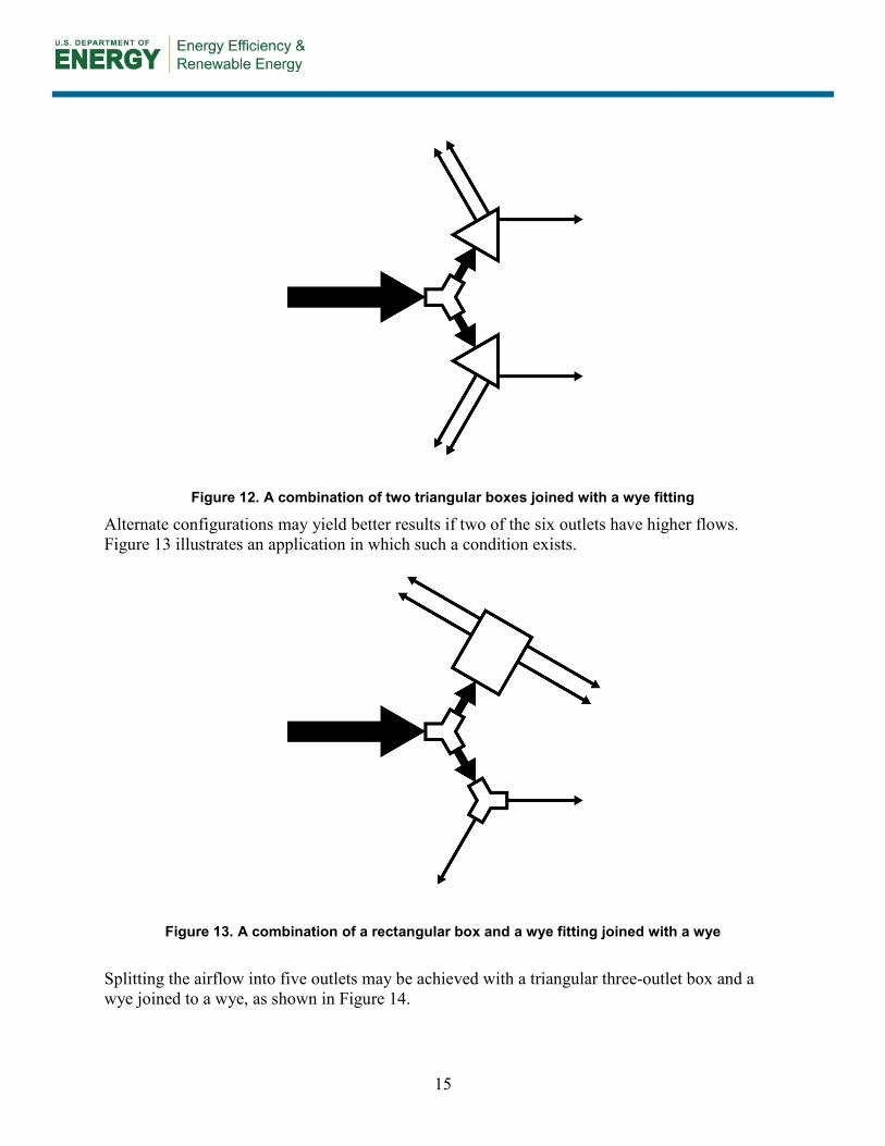
Splitting the airflow into six equal flow outlets, a symmetrical split using two triangular boxes could be used, as shown in Figure 12.
15
Figure 12. A combination of two triangular boxes joined with a wye fitting
Alternate configurations may yield better results if two of the six outlets have higher flows. Figure 13 illustrates an application in which such a condition exists.
Figure 13. A combination of a rectangular box and a wye fitting joined with a wye
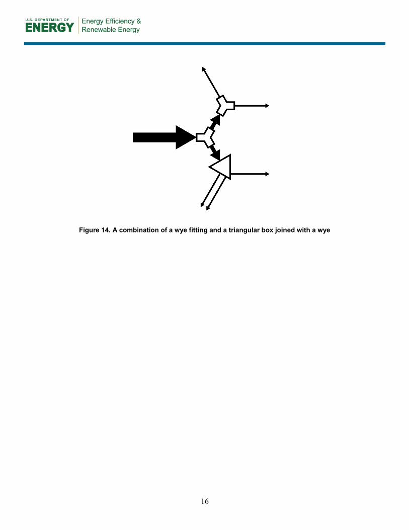
Splitting the airflow into five outlets may be achieved with a triangular three-outlet box and a wye joined to a wye, as shown in Figure 14.
16
Figure 14. A combination of a wye fitting and a triangular box joined with a wye
17
5 Verification Procedures and Tests
One often overlooked but critical step in implementing a successful and effective HVAC system is that the designer should clearly communicate with the contractor regarding how to build the junction boxes. More specifically, the designer should provide a detailed shop drawing of the junction box to the contractor. This step will help to ensure that the ELs remain valid in the as-built system and that the system corresponds with the intended design.
As mentioned, balancing of dampers is another critical step in ensuring that airflows are consistent and as designed. ACCA Manual D (Rutkowski 2009) requires that balancing dampers should be installed at all outlets and then adjusted for the desired airflows. If the airflows after balancing are within 10% of the design flow, then the balancing can be considered successful.
A Balancing Act: Balancing Airflow and Pressure with Dampers. Static pressure is a resistance to airflow due to restrictions created by components (e.g., duct friction), whereas available pressure is the difference between the static pressure and the pressure against which the selected equipment can deliver. This value is what is available in the design for duct and supply outlet pressure losses. In a well-designed system, the total pressure drop must not exceed the available static pressure of the equipment (Burdick 2011a). A duct system that is self-balancing would have to be sized so that the pressure drop for each circulation path is equal to the available static pressure. However, such a system is usually impractical because it would require complex and time-consuming calculations and nonstandard duct sizes, and the system could be noisy. Furthermore, a self-balancing system could compromise seasonal heating and cooling performance. In most cases, averaging the airflows between the heating and cooling requirements is a reasonable compromise (Rutkowski 2006). ACCA Manual D guidance (Rutkowski 2009) requires the installation of balancing dampers near each outlet. These dampers can be adjusted to restrict or allow airflow to a desired pressure level. However, because the duct system works as a complete system, the adjustment of pressure level at one outlet may change the pressure at another outlet. This makes balancing a difficult and time-consuming iterative process. Balancing also could be impossible if the duct runs are already enclosed by construction. Therefore, it is important to do the balancing prior to enclosing the ducts behind any walls or ceilings. Another alternative would be to place covered access holes in structural panels, which would allow access for balancing. ACCA also recommends the use of opposed blade dampers, with multiple blades, installed at the outlets. These devices are characterized by a pair of damper blades moving in opposite directions. Because so many factors can affect the pressure drop of each component of a system, correct balancing is necessary to ensure that the system functions as designed. For more details on balancing with dampers, see ACCA Manual D (Rutkowski 2009).
18
6 Summary
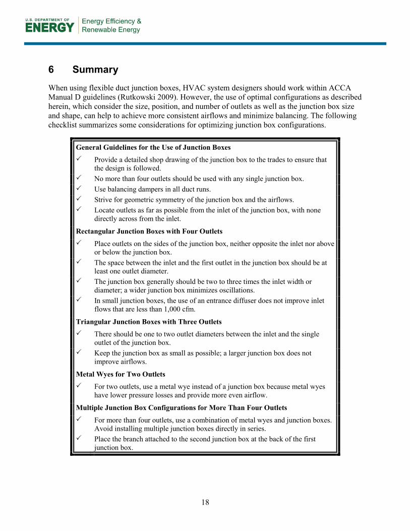
When using flexible duct junction boxes, HVAC system designers should work within ACCA Manual D guidelines (Rutkowski 2009). However, the use of optimal configurations as described herein, which consider the size, position, and number of outlets as well as the junction box size and shape, can help to achieve more consistent airflows and minimize balancing. The following checklist summarizes some considerations for optimizing junction box configurations.
General Guidelines for the Use of Junction Boxes Provide a detailed shop drawing of the junction box to the trades to ensure that
the design is followed. No more than four outlets should be used with any single junction box. Use balancing dampers in all duct runs. Strive for geometric symmetry of the junction box and the airflows. Locate outlets as far as possible from the inlet of the junction box, with none
directly across from the inlet.
Rectangular Junction Boxes with Four Outlets Place outlets on the sides of the junction box, neither opposite the inlet nor above
or below the junction box. The space between the inlet and the first outlet in the junction box should be at
least one outlet diameter. The junction box generally should be two to three times the inlet width or
diameter; a wider junction box minimizes oscillations. In small junction boxes, the use of an entrance diffuser does not improve inlet
flows that are less than 1,000 cfm.
Triangular Junction Boxes with Three Outlets There should be one to two outlet diameters between the inlet and the single
outlet of the junction box. Keep the junction box as small as possible; a larger junction box does not
improve airflows.
Metal Wyes for Two Outlets For two outlets, use a metal wye instead of a junction box because metal wyes
have lower pressure losses and provide more even airflow.
Multiple Junction Box Configurations for More Than Four Outlets For more than four outlets, use a combination of metal wyes and junction boxes.
Avoid installing multiple junction boxes directly in series. Place the branch attached to the second junction box at the back of the first
junction box.
19
References
ASHRAE (2012). 2012 ASHRAE Handbook: HVAC Applications. Atlanta, GA: ASHRAE.
Beach, R.; Prahl, D.; Lange, R. (2013). CFD Analysis of Flexible Duct Junction Box Design. Golden, CO: National Renewable Energy Laboratory. DOE/GO-102013-4297. http://apps1.eere.energy.gov/buildings/publications/pdfs/building_america/fluid_dynamics_flexduct.pdf.
Burdick, A. (2011a). Advanced Strategy Guideline: Air Distribution Basics and Duct Design. Golden, CO: National Renewable Energy Laboratory. NREL/SR-5500-53352. www.nrel.gov/docs/fy12osti/53352.pdf.
Burdick, A. (2011b). Strategy Guideline: Accurate Heating and Cooling Load Calculations. Golden, CO: National Renewable Energy Laboratory. NREL/SR-5500-51603. www.nrel.gov/docs/fy11osti/51603.pdf.
Rutkowski, H. (1995). Manual S—Residential Equipment Selection. Arlington, VA: Air Conditioning Contractors of America.
Rutkowski, H. (2006). Manual J—Residential Load Calculation, 8th edition, Version 2. Arlington, VA: Air Conditioning Contractors of America.
Rutkowski, H. (2009). Manual D—Residential Duct Systems, 3rd edition, Version 1.00. Arlington, VA: Air Conditioning Contractors of America.
DOE/GO-102014-4396 ▪ March 2014
Printed with a renewable-source ink on paper containing at least 50% wastepaper, including 10% post-consumer waste.
buildingamerica.gov