
OPTIMIZED DESIGN FOR HEAVY MOUND · PDF fileventuri scrubber, linear control, dust removal...
6
Xing, F., et al.: Optimized Design for Heavy Mound Venturi THERMAL SCIENCE, Year 2017, Vol. 21, No. 4, pp. 1873-1878 1873 OPTIMIZED DESIGN FOR HEAVY MOUND VENTURI by Futang XING * , Yuheng LI, Dan MEI, Shunfeng GUI, and Liya WANG Hubei Key Laboratory for Efficient Utilization and Agglomeration of Metallurgic Mineral Resources, Wuhan University of Science and Technology, Wuhan, China Original scientific paper https://doi.org/10.2298/TSCI161201102X The venturi scrubber is one of the most efficient gas cleaning devices for removal of contaminating particles in industrial flue-gas purification processes. The ve- locity of the gas entering the scrubber is one of the key factors influencing its dust-removal efficiency. In this study, the shapes of the heavy mound and tube wall are optimized, allowing the girth area to become linearly adjustable. The re- sulting uniformity of velocity distribution is verified numerically. Keywords: venturi scrubber, linear control, dust removal efficiency, optimization Introduction Numerous technologies are available for gas cleaning in different industries and power plants, including use of cyclones, settling chambers, fabric filters, electrostatic precipi- tators, and others, among which wet scrubbers are one of the most efficient devices for re- moving particles and gaseous contaminants from exhaust gases [1, 2]. These can be further categorized according to their configurations, which include spray-tower, mechanically aided, orifice, packed-bed, ionizing-wet, fiber-bed, moving-bed, tray, catenary-grid, condensation- growth, rod-deck, collision, ejector, and venturi scrubbers. The venturi scrubber is a highly efficient gas cleaning device that uses liquid drop- lets to remove dust particles with diameters ranging between 0.1 and 300 µm and absorb gas- eous contaminants, such as SO 2 , I 2 , and CH 3 I, from gaseous streams. A venturi scrubber has the following advantages: the structure is relatively simple and compact, the footprint is small, there are no rotating parts, it is easy to install and maintain, it exhibits high temperature and corrosion resistance, and it is capable of synergistic removal of both particulate and gase- ous pollutants [3]. A classical venturi scrubber consists of three main parts [4-8]: converging section, throat, and diffuser, as shown in fig. 1. The converging section is used to accelerate the gas to be cleaned to atomize the scrubbing liquid; the throat, located between the converging and diffuser sections, is where interaction of the liquid and gas takes place, and the diffuser per- mits deceleration of the gas to allow for some pressure recovery. The geometrical cross- section of a venturi scrubber can be either circular or rectangular. Venturi scrubbers, which have a successful history, are still a popular choice among gas cleaning devices because they are potentially capable of meeting future emission stand- ards with minimum modifications necessary to improve the collection of small particles. –––––––––––––– * Corresponding author, e-mail: [email protected]
Transcript of OPTIMIZED DESIGN FOR HEAVY MOUND · PDF fileventuri scrubber, linear control, dust removal...

Xing, F., et al.: Optimized Design for Heavy Mound Venturi THERMAL SCIENCE, Year 2017, Vol. 21, No. 4, pp. 1873-1878 1873
OPTIMIZED DESIGN FOR HEAVY MOUND VENTURI
by
Futang XING*, Yuheng LI, Dan MEI, Shunfeng GUI, and Liya WANG
Hubei Key Laboratory for Efficient Utilization and Agglomeration of Metallurgic Mineral Resources, Wuhan University of Science and Technology, Wuhan, China
Original scientific paper https://doi.org/10.2298/TSCI161201102X
The venturi scrubber is one of the most efficient gas cleaning devices for removal of contaminating particles in industrial flue-gas purification processes. The ve-locity of the gas entering the scrubber is one of the key factors influencing its dust-removal efficiency. In this study, the shapes of the heavy mound and tube wall are optimized, allowing the girth area to become linearly adjustable. The re-sulting uniformity of velocity distribution is verified numerically. Keywords: venturi scrubber, linear control, dust removal efficiency, optimization
Introduction
Numerous technologies are available for gas cleaning in different industries and power plants, including use of cyclones, settling chambers, fabric filters, electrostatic precipi-tators, and others, among which wet scrubbers are one of the most efficient devices for re-moving particles and gaseous contaminants from exhaust gases [1, 2]. These can be further categorized according to their configurations, which include spray-tower, mechanically aided, orifice, packed-bed, ionizing-wet, fiber-bed, moving-bed, tray, catenary-grid, condensation-growth, rod-deck, collision, ejector, and venturi scrubbers.
The venturi scrubber is a highly efficient gas cleaning device that uses liquid drop-lets to remove dust particles with diameters ranging between 0.1 and 300 µm and absorb gas-eous contaminants, such as SO2, I2, and CH3I, from gaseous streams. A venturi scrubber has the following advantages: the structure is relatively simple and compact, the footprint is small, there are no rotating parts, it is easy to install and maintain, it exhibits high temperature and corrosion resistance, and it is capable of synergistic removal of both particulate and gase-ous pollutants [3].
A classical venturi scrubber consists of three main parts [4-8]: converging section, throat, and diffuser, as shown in fig. 1. The converging section is used to accelerate the gas to be cleaned to atomize the scrubbing liquid; the throat, located between the converging and diffuser sections, is where interaction of the liquid and gas takes place, and the diffuser per-mits deceleration of the gas to allow for some pressure recovery. The geometrical cross-section of a venturi scrubber can be either circular or rectangular.
Venturi scrubbers, which have a successful history, are still a popular choice among gas cleaning devices because they are potentially capable of meeting future emission stand-ards with minimum modifications necessary to improve the collection of small particles.
–––––––––––––– * Corresponding author, e-mail: [email protected]

Xing, F., et al.: Optimized Design for Heavy Mound Venturi 1874 THERMAL SCIENCE, Year 2017, Vol. 21, No. 4, pp. 1873-1878
There are two main types of commercial venturi scrubbers. Namely, the constant-throat, Pease-Anthony [9], and variable-th-roat, McInnis-Bischoff [10] designs. To date, only a few studies have focused on the McInnis-Bischoff scrubber [11]. The main way in which current adjustable-throat venturi scrubbers can be modified is by adjusting the width of the throat.
The main factors affecting the dust-removal efficiency of ven-turi scrubbers are the liquid/gas ratio, particle size of the solid con-taminants, gaseous and liquid flow rates, and pressure drop. The present study analyzes the influence of gas velocity on the dust-removal efficiency of the McInnis-Bischoff-type scrubber. In a conventional scrubber, the profile of the heavy mound is parabolic, but that of the tube is linear. Therefore, the girth area varies with height of the mound. At certain flow rates, the velocity distribution will be non-uniform, which will cause loss of pressure. In this study, we propose a new design to improve the uniformity of gas velocity in these scrubbers.
Optimized mound design
If the throat area is set as S, then when the mound advances by an increment dx, then the throat area should be covered by area dS of the mound. Considering linear control, the re-lationship can be given:
d dS k x= (1)
The limiting conditions occur when the mound covers the throat entirely or not at all, which can be written as:
min max,mound throat max min,mound0, , , 0x x S S x x S= = = = = (2)
Therefore, k could be calculated:
throat
max
Skx
= (3)
Without loss of generality, the cross-section can be considered as a circle, i. e.:
2
moundπS r= (4) then
2 2
mound max mound
throat
π πr x rxk S
= = (5)
The profile of the heavy mound is therefore parabolic.
Optimized venturi tube design
When the mound travels a distance of dx, the non-covered throat area decreases by dSʹ, so:
d ' 'dS k x= (6)
Figure 1. Schematic of heavy mound venturi tube
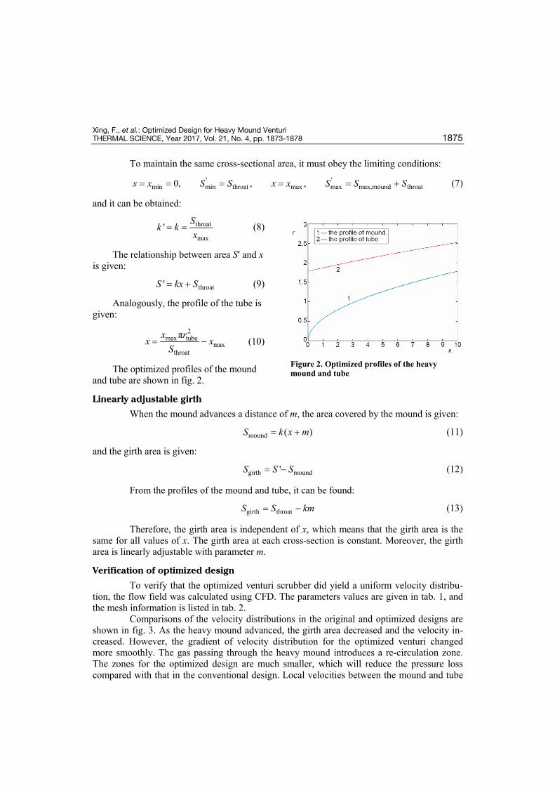
Xing, F., et al.: Optimized Design for Heavy Mound Venturi THERMAL SCIENCE, Year 2017, Vol. 21, No. 4, pp. 1873-1878 1875
To maintain the same cross-sectional area, it must obey the limiting conditions:
' 'min min throat max max max,mound throat0, , ,x x S S x x S S S= = = = = + (7)
and it can be obtained:
throat
max' Sk k
x= = (8)
The relationship between area Sʹ and x is given:
throat'S kx S= + (9)
Analogously, the profile of the tube is given:
2
max tubemax
throat
πx rx xS
= − (10)
The optimized profiles of the mound and tube are shown in fig. 2.
Linearly adjustable girth
When the mound advances a distance of m, the area covered by the mound is given:
mound ( )S k x m= + (11)
and the girth area is given:
girth mound'S S S= − (12)
From the profiles of the mound and tube, it can be found:
girth throatS S km= − (13)
Therefore, the girth area is independent of x, which means that the girth area is the same for all values of x. The girth area at each cross-section is constant. Moreover, the girth area is linearly adjustable with parameter m.
Verification of optimized design
To verify that the optimized venturi scrubber did yield a uniform velocity distribu-tion, the flow field was calculated using CFD. The parameters values are given in tab. 1, and the mesh information is listed in tab. 2.
Comparisons of the velocity distributions in the original and optimized designs are shown in fig. 3. As the heavy mound advanced, the girth area decreased and the velocity in-creased. However, the gradient of velocity distribution for the optimized venturi changed more smoothly. The gas passing through the heavy mound introduces a re-circulation zone. The zones for the optimized design are much smaller, which will reduce the pressure loss compared with that in the conventional design. Local velocities between the mound and tube
Figure 2. Optimized profiles of the heavy mound and tube

Xing, F., et al.: Optimized Design for Heavy Mound Venturi 1876 THERMAL SCIENCE, Year 2017, Vol. 21, No. 4, pp. 1873-1878
wall are listed in tab. 3. Theoretically, the velocity in the optimized design should be constant. However, the numerical results show slight differences due to the effect of the boundary lay-er. The fluctuation is relatively small for the optimized design.
Table 1. Parameters used in CFD modeling
Table 2. Meshes used in CFD modeling
Table 3. Local velocities for heavy mound at different heights
Parameter Value Parameter Value
Inlet diameter of converging section [m] 3 Gas flowrate [kgs–1] 350
Length of converging section [m] 3 Gas density [kgm–3] 1.185
Throat diameter [m] 2 Relative pressure [Pa] 0
Outlet diameter of diffuser [m] 4.6 Turbulent mode k-ε model
Length of diffuser [m] 4 Convergence criteria 1e−5
Height of heavy mound [m] 2
The minimum mesh size [mm] The number of grid The number of nodes
Before optimization 58 41536 38695
Heavy mound 31 9525 8720
After optimization 58 58159 54600
Heavy mound distance
[m]
Position from tube
wall at throat [m]
Numerical velocity after optimization
[ms–1]
Theoretical velocity after optimization
[ms–1]
Numerical velocity before optimization
[ms–1]
Theoretical velocity after optimization
[ms–1]
0 95.0292
99.0139
94.8096 99.0139
0.1 0.5 103.1540 109.257 107.6717
1 100.3500 119.768 115.9684
1.5 100.907 122.28 123.3617
0 112.1630
117.5791
113.077 117.5791
0.4 0.4 119.1420 126.14 127.4593
0.8 120.878 139.272 137.4301
1.2 113.454 145.262 146.9739
0.7
0 138.6010
144.7127
132.225 144.7127
0.4 142.791 157.139 160.032
0.8 148.96 182.959 176.0019
1.2 135.422 175.742 191.9658

Xing, F., et al.: Optimized Design for Heavy Mound Venturi THERMAL SCIENCE, Year 2017, Vol. 21, No. 4, pp. 1873-1878 1877
Figure 3. Comparison of velocity distributions of conventional (left) and optimized (right) venturi scrubber designs for mound distances of (a) 0.1 m, (b) 0.4 m, and (c) 0.7 m (for color image see journal web site)

Xing, F., et al.: Optimized Design for Heavy Mound Venturi 1878 THERMAL SCIENCE, Year 2017, Vol. 21, No. 4, pp. 1873-1878
Conclusion
An optimized design for a heavy mound venturi is proposed. The profiles of both the mound and tube are parabolic. Compared with the conventional structure, the girth area be-comes linearly adjustable, which has benefits for improving the efficiency and reducing the noise of the venturi tube. The CFD simulation verified that the optimized design exhibited a more uniform gas velocity distribution.
Acknowledgment
The author gratefully acknowledges the support of the Hubei Provincial Natural Sci-ence Foundation (2016CFC750).
References [1] Lim, K. S. et al., Prediction for Particle Removal Efficiency of a Reverse Jet Scrubber, Aerosol Sci., 12
(2006), 37, pp. 1826-1839 [2] Mayinger, F., Lehner, M., Operating Results and Aerosol Deposition of a Venture Scrubber in Self-
Priming Operation, Chem. Eng. Process, 34 (1995), 3, pp. 283-288 [3] Economopoulou, A. A., Harrison, R. M., Graphical Analysis of the Performance of Venturi Scrubbers
for Particle Abatement, Part I: Rapid Collection Efficiency Evaluation, Aerosol Sci. Technol., 41 (2007), 1, pp. 51-62
[4] Lehner, M., Aerosol Separation Efficiency of a Venturi Scrubber Working in Self-Priming Model, Aero-sol Sci. Technol., 28 (1998), 5, pp. 389-402
[5] Gamisan, X., et al., The Hydrodynamics of Ejector Venturi Scrubbers and their Modeling by an Annu-lar/Flow Boundary Layer Model, Chem. Eng. Sci., 57 (2002), 14, pp. 2707-2718
[6] Placek, T. D., Peters, L. K., Analysis of Particulate Removal in Venturi Scrubbers-Effect of Operating Variables on Performance, AIChE J., 27 (1981), 6, pp. 984-993
[7] Monabbati, M., et al., Test of Mathematical Modeling for the Design of High-Energy Scrubbers., Aero-sol. Sci., 20 (1989), 8, pp. 1441-1444
[8] Costa, M. A. M., et al., Performance of a Venturi Scrubber in the Removal of Fine Powder from a Con-fined Gas Stream, Mater, Res., 8 (2005), 2, pp. 177-179
[9] Pak, S. I., Chang, K. S., Performance Estimation of a Venturi Scrubber Using a Computational Model for Capturing Dust Particles with Liquid Spray, Hazard. Mater., 138 (2006), 3, pp. 560-573
[10] Steven, R., A Dimensional Analysis of Two-Phase Flow through a Horizontally Installed Venturi Flow Meter, Flow Meas. Instrum., 19 (2008), 6, pp. 342-349
[11] Emiroglu, M. E., Baylar, A., Study of the Influence of Air Holes along Length of Convergent-Divergent Passage of a Venturi Device on Aeration, Hydraul. Res., 41 (2003), 5, pp. 513-520
Paper submitted: December 1, 2016 © 2017 Society of Thermal Engineers of Serbia. Paper revised: March 1, 2017 Published by the Vinča Institute of Nuclear Sciences, Belgrade, Serbia. Paper accepted: March 21, 2017 This is an open access article distributed under the CC BY-NC-ND 4.0 terms and conditions.


![Scrubbing of HCl Gas from Synthesis Gas in a Multistage ... · Bubble Column Scrubber. Bangwoo Han et al. [14] have observed the HCl removal in a packed bed scrubber for four different](https://static.fdocuments.net/doc/165x107/5e1b55ca25edd10a785d1331/scrubbing-of-hcl-gas-from-synthesis-gas-in-a-multistage-bubble-column-scrubber.jpg)


