OPTIMIZE MRO - Ansys
4
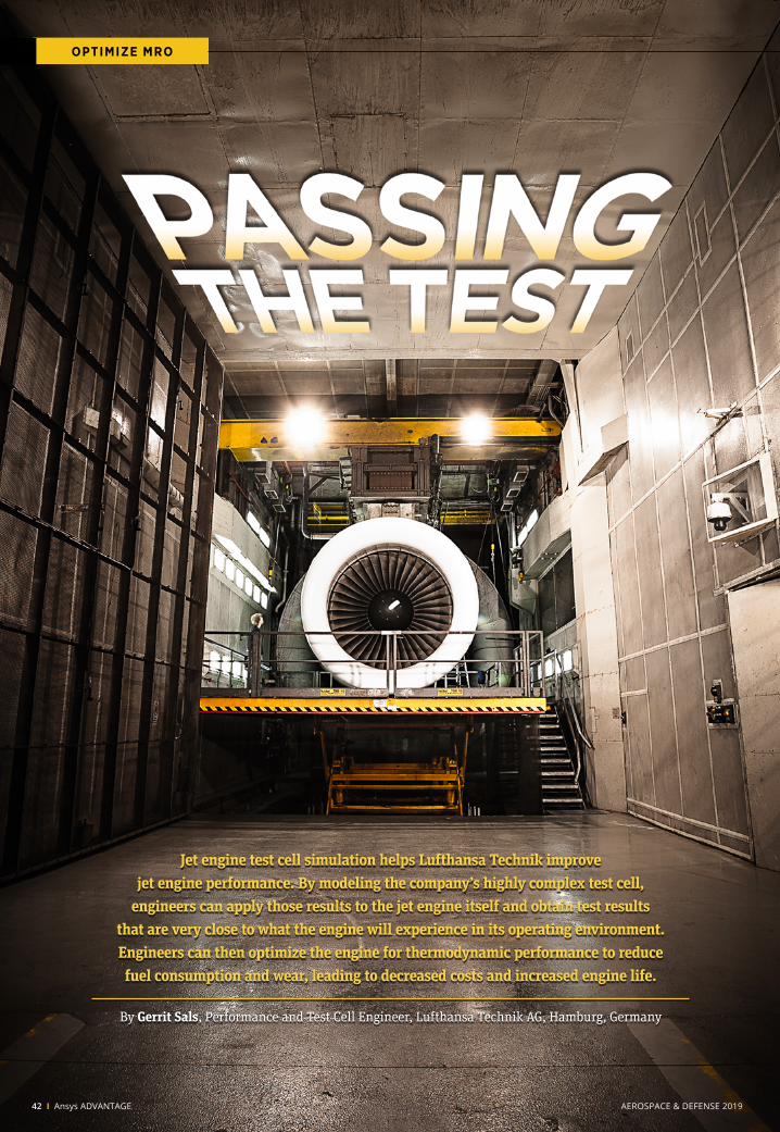
Jet engine test cell simulation helps Lufthansa Technik improve jet engine performance. By modeling the company’s highly complex test cell, engineers can apply those results to the jet engine itself and obtain test results that are very close to what the engine will experience in its operating environment. Engineers can then optimize the engine for thermodynamic performance to reduce fuel consumption and wear, leading to decreased costs and increased engine life. By Gerrit Sals, Performance and Test Cell Engineer, Lufthansa Technik AG, Hamburg, Germany OPTIMIZE MRO 42 I Ansys ADVANTAGE AEROSPACE & DEFENSE 2019
Transcript of OPTIMIZE MRO - Ansys
Jet engine test cell simulation helps Lufthansa Technik improve jet engine performance. By modeling the company’s highly complex test cell,
engineers can apply those results to the jet engine itself and obtain test results that are very close to what the engine will experience in its operating environment. Engineers can then optimize the engine for thermodynamic performance to reduce fuel consumption and wear, leading to decreased costs and increased engine life.
By Gerrit Sals, Performance and Test Cell Engineer, Lufthansa Technik AG, Hamburg, Germany
OPTIMIZE MRO
42 I Ansys ADVANTAGE AEROSPACE & DEFENSE 2019

Overhauling a typical commercial jet aircraft engine might cost about $2 million as an expert team inspects and services or replaces up to 40,000 parts. Such an overhaul could be necessary each time the engine flies between 2,000 and 10,000 flights. Overhauls can vary greatly in their work scope, which describes the engine components that are to be serviced or replaced. The work scope is vital because it largely determines the overhaul cost and the performance of the overhauled engine. Lufthansa Technik is improving the engine overhaul process by simulating individual engines at a very detailed level to quantify the relationship between the condition of specific components and the operating behavior of the engine. The insight gained from these simulations allows the team to develop a customized work scope in close consultation with the customer. This work scope might allow engineers to increase the thermodynamic engine performance, which reduces fuel consumption and wear, thereby decreasing future maintenance costs. The understanding acquired from simulation also makes it possible to obtain maximum use from thermo-dynamically as well as economically critical parts, for example, by operating expensive turbine blades for longer periods. Until recently, these simulations were based solely on the engine operating in the air or on the runway, in contrast to jet engine diagnosis and acceptance testing, which is performed in test cells where operating conditions can be significantly different. Lufthansa Technik engineers have long wanted to simulate engines as if they were operating on the company’s jet engine test cell. This would require modeling the test cell so the results could be used in modeling the engine. However, test cells are challenging to simulate due to the size and complexity of the geometry, the large range of length and velocity scales present, and flow Mach numbers ranging from near zero to transonic. Lufthansa Technik engineers have recently overcome these challenges by simulating one of the company’s test cells and validating the results against physical testing measurements. Once the team is able to use the test cell simulation results as input to the engine simulation, engineers will be able to better understand the results of diagnostic testing in the test cells, and will also be better able to predict the effects of different overhaul work procedures on acceptance testing. The result should be improvements in engine performance and more accurate overhaul work scoping with resulting cost reductions.
Optimizing the Overhaul ProcessLufthansa Technik AG is one of the world’s leading providers of aircraft maintenance, repair and overhaul services. To improve engine efficiency while avoiding unnecessary work during engine overhauls, detailed knowledge of the internal interactions in the engine is essential. Lufthansa Technik constantly monitors important components so they can be replaced as a function of their condition. Further efficiency improvement can be achieved by precisely determining how the condition of individual components will affect the engine behavior as a whole. By establishing this link between component condition and the operating behavior of the engine, it is possible to target critical components to address during overhaul.
Outer boundary conditions
Jet engine test cell simulation helps Lufthansa Technik improve jet engine performance. By modeling the company’s highly complex test cell,
engineers can apply those results to the jet engine itself and obtain test results that are very close to what the engine will experience in its operating environment. Engineers can then optimize the engine for thermodynamic performance to reduce fuel consumption and wear, leading to decreased costs and increased engine life.
By Gerrit Sals, Performance and Test Cell Engineer, Lufthansa Technik AG, Hamburg, Germany
Test CellInlet
Environment
TurbulenceScreen
BlastBasket
Interfaces
TestChamber
ExhaustStack
Part A
Part B Part C
Part D
The test cell was partitioned into five models joined with interfaces to enable simulation of the complex model.
42 I Ansys ADVANTAGE AEROSPACE & DEFENSE 2019 © 2017 ANSYS, Inc. Ansys ADVANTAGE I 43
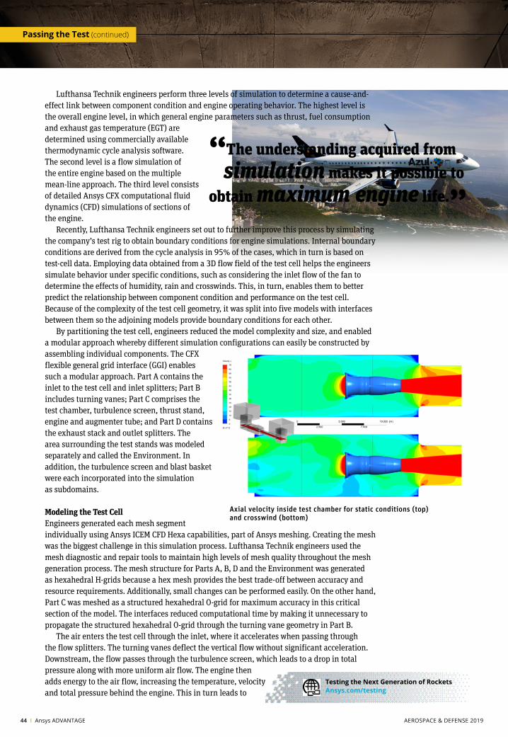
Lufthansa Technik engineers perform three levels of simulation to determine a cause-and-effect link between component condition and engine operating behavior. The highest level is the overall engine level, in which general engine parameters such as thrust, fuel consumption and exhaust gas temperature (EGT) are determined using commercially available thermodynamic cycle analysis software. The second level is a flow simulation of the entire engine based on the multiple mean-line approach. The third level consists of detailed Ansys CFX computational fluid dynamics (CFD) simulations of sections of the engine. Recently, Lufthansa Technik engineers set out to further improve this process by simulating the company’s test rig to obtain boundary conditions for engine simulations. Internal boundary conditions are derived from the cycle analysis in 95% of the cases, which in turn is based on test-cell data. Employing data obtained from a 3D flow field of the test cell helps the engineers simulate behavior under specific conditions, such as considering the inlet flow of the fan to determine the effects of humidity, rain and crosswinds. This, in turn, enables them to better predict the relationship between component condition and performance on the test cell. Because of the complexity of the test cell geometry, it was split into five models with interfaces between them so the adjoining models provide boundary conditions for each other. By partitioning the test cell, engineers reduced the model complexity and size, and enabled a modular approach whereby different simulation configurations can easily be constructed by assembling individual components. The CFX flexible general grid interface (GGI) enables such a modular approach. Part A contains the inlet to the test cell and inlet splitters; Part B includes turning vanes; Part C comprises the test chamber, turbulence screen, thrust stand, engine and augmenter tube; and Part D contains the exhaust stack and outlet splitters. The area surrounding the test stands was modeled separately and called the Environment. In addition, the turbulence screen and blast basket were each incorporated into the simulation as subdomains.
Modeling the Test CellEngineers generated each mesh segment individually using Ansys ICEM CFD Hexa capabilities, part of Ansys meshing. Creating the mesh was the biggest challenge in this simulation process. Lufthansa Technik engineers used the mesh diagnostic and repair tools to maintain high levels of mesh quality throughout the mesh generation process. The mesh structure for Parts A, B, D and the Environment was generated as hexahedral H-grids because a hex mesh provides the best trade-off between accuracy and resource requirements. Additionally, small changes can be performed easily. On the other hand, Part C was meshed as a structured hexahedral O-grid for maximum accuracy in this critical section of the model. The interfaces reduced computational time by making it unnecessary to propagate the structured hexahedral O-grid through the turning vane geometry in Part B. The air enters the test cell through the inlet, where it accelerates when passing through the flow splitters. The turning vanes deflect the vertical flow without significant acceleration. Downstream, the flow passes through the turbulence screen, which leads to a drop in total pressure along with more uniform air flow. The engine then adds energy to the air flow, increasing the temperature, velocity and total pressure behind the engine. This in turn leads to
“The understanding acquired from simulation makes it possible to obtain maximum engine life.”
Axial velocity inside test chamber for static conditions (top) and crosswind (bottom)
Passing the Test (continued)
44 I Ansys ADVANTAGE AEROSPACE & DEFENSE 2019
Testing the Next Generation of Rockets Ansys.com/testing
an acceleration of the air bypassing the engine, which is called the ejector effect. The exhaust gas then leaves the test cell through the aug- menter tube, blast basket and exhaust stack. Engineers simulated the test under two different sets of environmental conditions, which were used as boundary conditions. The first assumed no air movement at the inlet and outlet of the test cell, and the second assumed a 20 m/s crosswind at the inlet and outlet. While different wind directions and speeds are not used in testing, adjustments were made to the CFD model to account for crosswinds, and simulation was used to evaluate those adjustments. The external boundary conditions, which are needed only during the crosswind simulation, include an inlet in front, an outlet at the rear, and open-ings in the left, top and right of the model. The model’s internal outlet boundary (engine inlet) is dependent on the model’s internal inlet boundary (engine outlet). The mass flow of these boundaries is coupled through functions based on the static pressure and total temperature at the engine’s exhaust nozzle. The functions were derived using thermodynamic cycle analysis. This setup increases the accuracy of the model as the engine changes its operating point according to the test cell flow conditions.
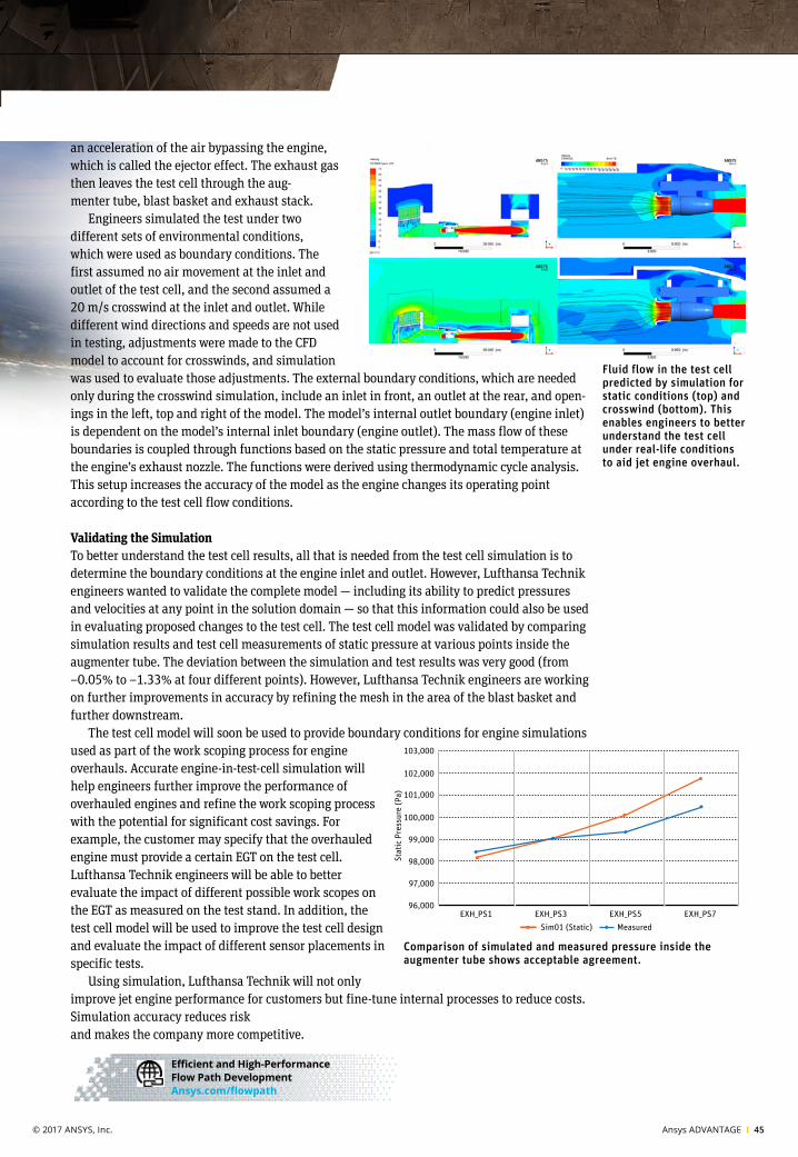
Validating the SimulationTo better understand the test cell results, all that is needed from the test cell simulation is to determine the boundary conditions at the engine inlet and outlet. However, Lufthansa Technik engineers wanted to validate the complete model — including its ability to predict pressures and velocities at any point in the solution domain — so that this information could also be used in evaluating proposed changes to the test cell. The test cell model was validated by comparing simulation results and test cell measurements of static pressure at various points inside the augmenter tube. The deviation between the simulation and test results was very good (from –0.05% to –1.33% at four different points). However, Lufthansa Technik engineers are working on further improvements in accuracy by refining the mesh in the area of the blast basket and further downstream. The test cell model will soon be used to provide boundary conditions for engine simulations used as part of the work scoping process for engine overhauls. Accurate engine-in-test-cell simulation will help engineers further improve the performance of overhauled engines and refine the work scoping process with the potential for significant cost savings. For example, the customer may specify that the overhauled engine must provide a certain EGT on the test cell. Lufthansa Technik engineers will be able to better evaluate the impact of different possible work scopes on the EGT as measured on the test stand. In addition, the test cell model will be used to improve the test cell design and evaluate the impact of different sensor placements in specific tests. Using simulation, Lufthansa Technik will not only improve jet engine performance for customers but fine-tune internal processes to reduce costs. Simulation accuracy reduces risk and makes the company more competitive.
103,000
102,000
101,000
100,000
99,000
98,000
97,000
96,000
Sim01 (Static) Measured
Stat
ic P
ress
ure
(Pa)
EXH_PS1 EXH_PS3 EXH_PS5 EXH_PS7
Fluid flow in the test cell predicted by simulation for static conditions (top) and crosswind (bottom). This enables engineers to better understand the test cell under real-life conditions to aid jet engine overhaul.
Comparison of simulated and measured pressure inside the augmenter tube shows acceptable agreement.
Efficient and High-Performance Flow Path Development Ansys.com/flowpath
Axial velocity inside test chamber for static conditions (top) and crosswind (bottom)
44 I Ansys ADVANTAGE AEROSPACE & DEFENSE 2019 © 2017 ANSYS, Inc. Ansys ADVANTAGE I 45