
Optimization of Turning Process Parameters for Mild Steel
6
IJSRD - International Journal for Scientific Research & Development| Vol. 3, Issue 11, 2016 | ISSN (online): 2321-0613 All rights reserved by www.ijsrd.com 102 Optimization of Turning Process Parameters for Mild Steel Prof. Alpesh R. Patel 1 Prof. Lalit S. Patel 2 Prof. Tejas C. Patel 3 1,3 Assistant Professor 2 Research Scholar 1 Government Engineering College, Valsad, Gujarat, India 2 Rai University, Ahmedabad, Gujarat, India 3 Shree Swami Atmanand Saraswati Institute of Technology, Surat, Gujarat, India Abstract— The present research paper is focused on the analysis of optimum cutting conditions to get lowest cutting forces in turning of mild steel material. The experimental result analysis showed that the optimum combination of various input factors as type of insert type, work piece material, Approach Angle, feed and depth of cut. Further, the confirmation tests are conducted and the results are found to be increased with increment of feed and depth of cut. Key words: Turning, Mild Steel, Lathe Machine, Cutting Forces, Optimization I. INTRODUCTION This project is on the analysis of the effect in change of different parameters in turning process. The various parameters that are important in turning are, A. Machining Feed: There are different feeds available on the lathe machine, which are varied to determine the effect of feed on the cutting forces. B. Depth of Cut: The depth of cut can be varied with the help of micrometer dial on the cross-slide. C. Approach Angle: Different approach angles will be taken for the analysis. Other tool geometry will be kept constant. Tool material will also be kept same. II. MACHINES/ INSTRUMENTS REQUIRED The details of machines and equipment available in workshop on which the project will be carried out are given below: A. Lathe Machine: Fig. 1: Lathe Machine Type Range of speeds (RPM) Range of feed Main motor Table feed motor(hp) HMT Lathe 32,52,88,150,250,420 710,1200 [0.05,0.06,0.07,0.10,0.13,0.15] [0.20,0.26,0.30,0.40,0.52,0.6] [0.83,1.04,1.25,1.65,2.08,2.5] 2 1 Table 1: Lathe Machine B. Dynamometer: For the measurement of cutting forces a three component strain gauge type lathe tool dynamometer is used for the present work. It consists of orthogonal ring and used to measure force values in three directions, one vertical direction two force components in longitude and transverse direction. The assembly consists of four octagonal rings arranged at right angles to each other and strain gauges which are fixed between two thick plates. Range of force measurement is 0-500 kg in all directions. Two rings are used to measure forces in feed direction and the other two in axial direction and all the four rings for the vertical component of cutting force. All the rings are identical in shape and can measure forces in three mutual perpendicular directions The Dynamometer is divided into the following subunits. Sensing unit: the sensing unit consists of four orthogonal rings with strain gauges cemented on arms. The unit accurately senses forces in three axes to the bridge circuit. Bridge balancing unit: The bridge balancing unit consists of power supply used to supply power to three bridge circuits. Measuring unit: A standard DC motors are provided to measure the output of the bridge unit directions in terms of kg. Some instructions are necessary for bridge balancing unit before performing the operations. Fig. 2: Sharp Dynamometer (Strain Gauge) The sensing unit of dynamometer should be in proper position on the lathe machine tool post. With help of
-
Upload
international-journal-for-scientific-research-and-development -
Category
Documents
-
view
16 -
download
4
description
The present research paper is focused on the analysis of optimum cutting conditions to get lowest cutting forces in turning of mild steel material. The experimental result analysis showed that the optimum combination of various input factors as type of insert type, work piece material, Approach Angle, feed and depth of cut. Further, the confirmation tests are conducted and the results are found to be increased with increment of feed and depth of cut.
Transcript of Optimization of Turning Process Parameters for Mild Steel
IJSRD - International Journal for Scientific Research & Development| Vol. 3, Issue 11, 2016 | ISSN (online): 2321-0613
All rights reserved by www.ijsrd.com 102
Optimization of Turning Process Parameters for Mild Steel Prof. Alpesh R. Patel1 Prof. Lalit S. Patel2 Prof. Tejas C. Patel3
1,3Assistant Professor 2Research Scholar 1Government Engineering College, Valsad, Gujarat, India
2Rai University, Ahmedabad, Gujarat, India 3Shree Swami Atmanand Saraswati Institute of Technology, Surat, Gujarat, India
Abstract— The present research paper is focused on the
analysis of optimum cutting conditions to get lowest cutting
forces in turning of mild steel material. The experimental
result analysis showed that the optimum combination of
various input factors as type of insert type, work piece
material, Approach Angle, feed and depth of cut. Further,
the confirmation tests are conducted and the results are
found to be increased with increment of feed and depth of
cut.
Key words: Turning, Mild Steel, Lathe Machine, Cutting
Forces, Optimization
I. INTRODUCTION
This project is on the analysis of the effect in change of
different parameters in turning process. The various
parameters that are important in turning are,
A. Machining Feed:
There are different feeds available on the lathe machine,
which are varied to determine the effect of feed on the
cutting forces.
B. Depth of Cut:
The depth of cut can be varied with the help of micrometer
dial on the cross-slide.
C. Approach Angle:
Different approach angles will be taken for the analysis.
Other tool geometry will be kept constant.
Tool material will also be kept same.
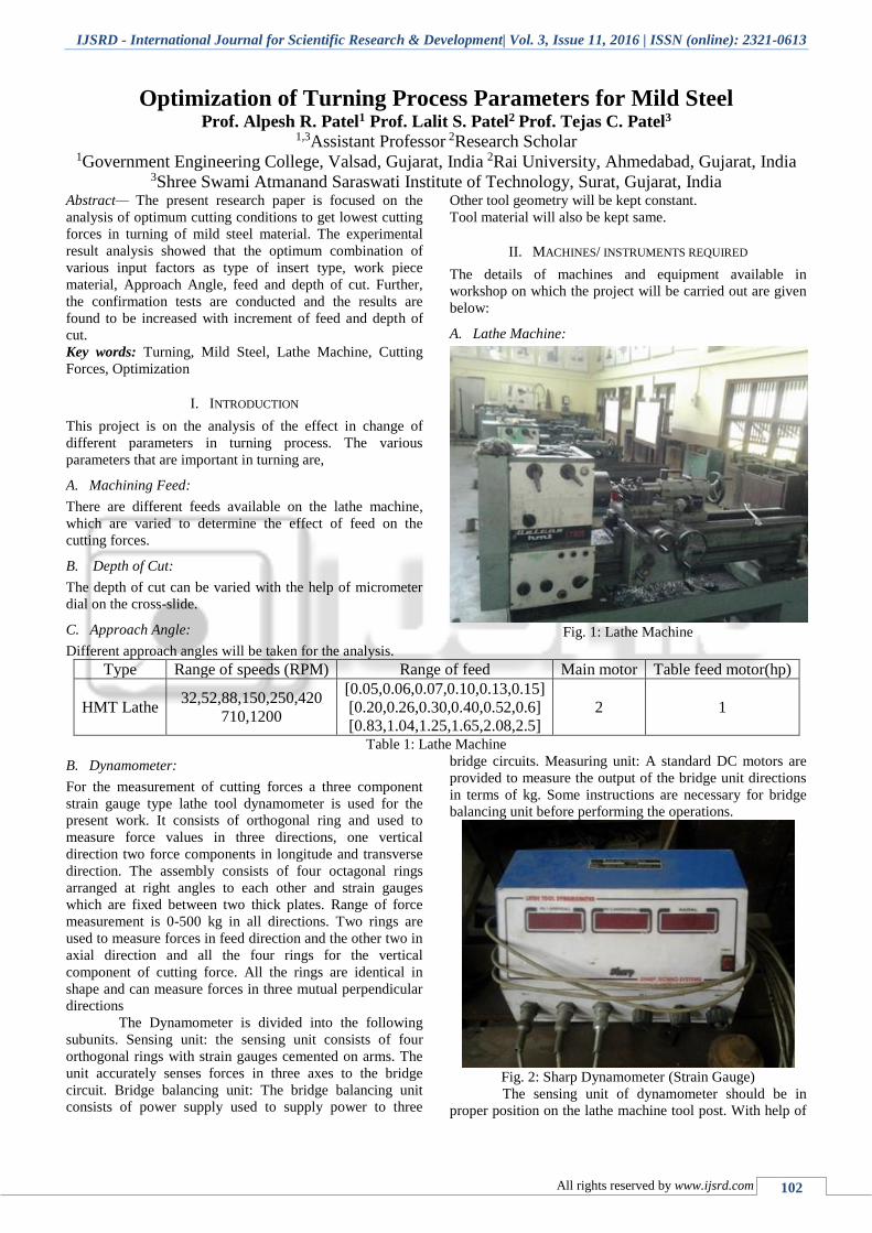
II. MACHINES/ INSTRUMENTS REQUIRED
The details of machines and equipment available in
workshop on which the project will be carried out are given
below:
A. Lathe Machine:
Fig. 1: Lathe Machine
Type Range of speeds (RPM) Range of feed Main motor Table feed motor(hp)
HMT Lathe 32,52,88,150,250,420
710,1200
[0.05,0.06,0.07,0.10,0.13,0.15]
[0.20,0.26,0.30,0.40,0.52,0.6]
[0.83,1.04,1.25,1.65,2.08,2.5]
2 1
Table 1: Lathe Machine
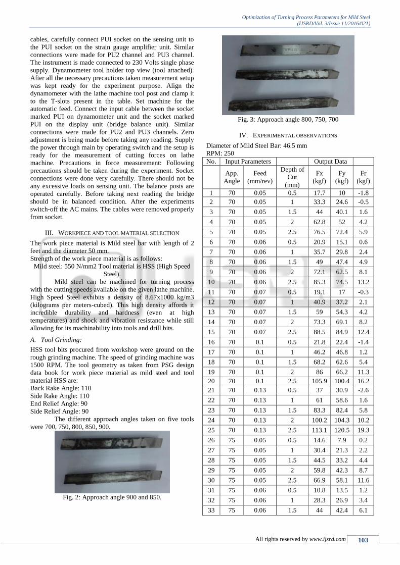
B. Dynamometer:
For the measurement of cutting forces a three component
strain gauge type lathe tool dynamometer is used for the
present work. It consists of orthogonal ring and used to
measure force values in three directions, one vertical
direction two force components in longitude and transverse
direction. The assembly consists of four octagonal rings
arranged at right angles to each other and strain gauges
which are fixed between two thick plates. Range of force
measurement is 0-500 kg in all directions. Two rings are
used to measure forces in feed direction and the other two in
axial direction and all the four rings for the vertical
component of cutting force. All the rings are identical in
shape and can measure forces in three mutual perpendicular
directions
The Dynamometer is divided into the following
subunits. Sensing unit: the sensing unit consists of four
orthogonal rings with strain gauges cemented on arms. The
unit accurately senses forces in three axes to the bridge
circuit. Bridge balancing unit: The bridge balancing unit
consists of power supply used to supply power to three
bridge circuits. Measuring unit: A standard DC motors are
provided to measure the output of the bridge unit directions
in terms of kg. Some instructions are necessary for bridge
balancing unit before performing the operations.
Fig. 2: Sharp Dynamometer (Strain Gauge)
The sensing unit of dynamometer should be in
proper position on the lathe machine tool post. With help of
Optimization of Turning Process Parameters for Mild Steel
(IJSRD/Vol. 3/Issue 11/2016/021)
All rights reserved by www.ijsrd.com 103
cables, carefully connect PUI socket on the sensing unit to
the PUI socket on the strain gauge amplifier unit. Similar
connections were made for PU2 channel and PU3 channel.
The instrument is made connected to 230 Volts single phase
supply. Dynamometer tool holder top view (tool attached).
After all the necessary precautions taken measurement setup
was kept ready for the experiment purpose. Align the
dynamometer with the lathe machine tool post and clamp it
to the T-slots present in the table. Set machine for the
automatic feed. Connect the input cable between the socket
marked PUI on dynamometer unit and the socket marked
PUI on the display unit (bridge balance unit). Similar
connections were made for PU2 and PU3 channels. Zero
adjustment is being made before taking any reading. Supply
the power through main by operating switch and the setup is
ready for the measurement of cutting forces on lathe
machine. Precautions in force measurement: Following
precautions should be taken during the experiment. Socket
connections were done very carefully. There should not be
any excessive loads on sensing unit. The balance posts are
operated carefully. Before taking next reading the bridge
should be in balanced condition. After the experiments
switch-off the AC mains. The cables were removed properly
from socket.
III. WORKPIECE AND TOOL MATERIAL SELECTION
The work piece material is Mild steel bar with length of 2
feet and the diameter 50 mm.
Strength of the work piece material is as follows:
Mild steel: 550 N/mm2 Tool material is HSS (High Speed
Steel).
Mild steel can be machined for turning process
with the cutting speeds available on the given lathe machine.
High Speed Steel exhibits a density of 8.67x1000 kg/m3
(kilograms per meters-cubed). This high density affords it
incredible durability and hardness (even at high
temperatures) and shock and vibration resistance while still
allowing for its machinability into tools and drill bits.
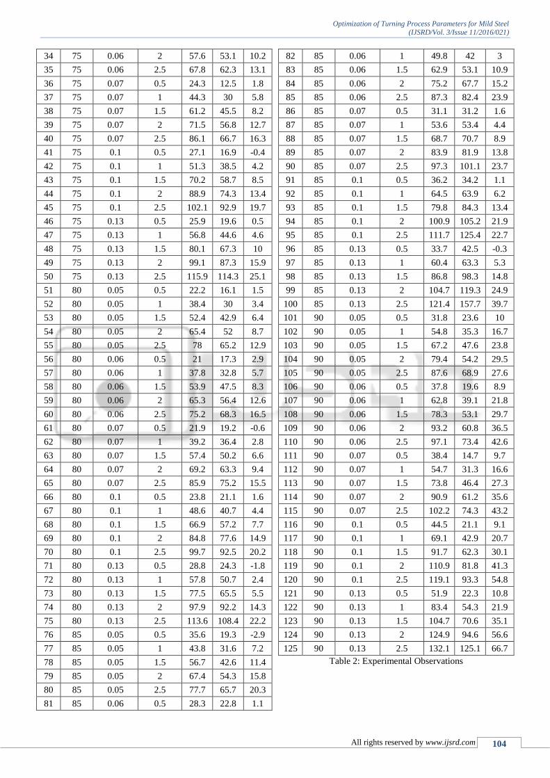
A. Tool Grinding:
HSS tool bits procured from workshop were ground on the
rough grinding machine. The speed of grinding machine was
1500 RPM. The tool geometry as taken from PSG design
data book for work piece material as mild steel and tool
material HSS are:
Back Rake Angle: 110
Side Rake Angle: 110
End Relief Angle: 90
Side Relief Angle: 90
The different approach angles taken on five tools
were 700, 750, 800, 850, 900.
Fig. 2: Approach angle 900 and 850.
Fig. 3: Approach angle 800, 750, 700
IV. EXPERIMENTAL OBSERVATIONS
Diameter of Mild Steel Bar: 46.5 mm
RPM: 250
No. Input Parameters Output Data
App.
Angle
Feed
(mm/rev)
Depth of
Cut
(mm)
Fx
(kgf)
Fy
(kgf)
Fr
(kgf)
1 70 0.05 0.5 17.7 10 -1.8
2 70 0.05 1 33.3 24.6 -0.5
3 70 0.05 1.5 44 40.1 1.6
4 70 0.05 2 62.8 52 4.2
5 70 0.05 2.5 76.5 72.4 5.9
6 70 0.06 0.5 20.9 15.1 0.6
7 70 0.06 1 35.7 29.8 2.4
8 70 0.06 1.5 49 47.4 4.9
9 70 0.06 2 72.1 62.5 8.1
10 70 0.06 2.5 85.3 74.5 13.2
11 70 0.07 0.5 19.1 17 -0.3
12 70 0.07 1 40.9 37.2 2.1
13 70 0.07 1.5 59 54.3 4.2
14 70 0.07 2 73.3 69.1 8.2
15 70 0.07 2.5 88.5 84.9 12.4
16 70 0.1 0.5 21.8 22.4 -1.4
17 70 0.1 1 46.2 46.8 1.2
18 70 0.1 1.5 68.2 62.6 5.4
19 70 0.1 2 86 66.2 11.3
20 70 0.1 2.5 105.9 100.4 16.2
21 70 0.13 0.5 37 30.9 -2.6
22 70 0.13 1 61 58.6 1.6
23 70 0.13 1.5 83.3 82.4 5.8
24 70 0.13 2 100.2 104.3 10.2
25 70 0.13 2.5 113.1 120.5 19.3
26 75 0.05 0.5 14.6 7.9 0.2
27 75 0.05 1 30.4 21.3 2.2
28 75 0.05 1.5 44.5 33.2 4.4
29 75 0.05 2 59.8 42.3 8.7
30 75 0.05 2.5 66.9 58.1 11.6
31 75 0.06 0.5 10.8 13.5 1.2
32 75 0.06 1 28.3 26.9 3.4
33 75 0.06 1.5 44 42.4 6.1
Optimization of Turning Process Parameters for Mild Steel
(IJSRD/Vol. 3/Issue 11/2016/021)
All rights reserved by www.ijsrd.com 104
34 75 0.06 2 57.6 53.1 10.2
35 75 0.06 2.5 67.8 62.3 13.1
36 75 0.07 0.5 24.3 12.5 1.8
37 75 0.07 1 44.3 30 5.8
38 75 0.07 1.5 61.2 45.5 8.2
39 75 0.07 2 71.5 56.8 12.7
40 75 0.07 2.5 86.1 66.7 16.3
41 75 0.1 0.5 27.1 16.9 -0.4
42 75 0.1 1 51.3 38.5 4.2
43 75 0.1 1.5 70.2 58.7 8.5
44 75 0.1 2 88.9 74.3 13.4
45 75 0.1 2.5 102.1 92.9 19.7
46 75 0.13 0.5 25.9 19.6 0.5
47 75 0.13 1 56.8 44.6 4.6
48 75 0.13 1.5 80.1 67.3 10
49 75 0.13 2 99.1 87.3 15.9
50 75 0.13 2.5 115.9 114.3 25.1
51 80 0.05 0.5 22.2 16.1 1.5
52 80 0.05 1 38.4 30 3.4
53 80 0.05 1.5 52.4 42.9 6.4
54 80 0.05 2 65.4 52 8.7
55 80 0.05 2.5 78 65.2 12.9
56 80 0.06 0.5 21 17.3 2.9
57 80 0.06 1 37.8 32.8 5.7
58 80 0.06 1.5 53.9 47.5 8.3
59 80 0.06 2 65.3 56.4 12.6
60 80 0.06 2.5 75.2 68.3 16.5
61 80 0.07 0.5 21.9 19.2 -0.6
62 80 0.07 1 39.2 36.4 2.8
63 80 0.07 1.5 57.4 50.2 6.6
64 80 0.07 2 69.2 63.3 9.4
65 80 0.07 2.5 85.9 75.2 15.5
66 80 0.1 0.5 23.8 21.1 1.6
67 80 0.1 1 48.6 40.7 4.4
68 80 0.1 1.5 66.9 57.2 7.7
69 80 0.1 2 84.8 77.6 14.9
70 80 0.1 2.5 99.7 92.5 20.2
71 80 0.13 0.5 28.8 24.3 -1.8
72 80 0.13 1 57.8 50.7 2.4
73 80 0.13 1.5 77.5 65.5 5.5
74 80 0.13 2 97.9 92.2 14.3
75 80 0.13 2.5 113.6 108.4 22.2
76 85 0.05 0.5 35.6 19.3 -2.9
77 85 0.05 1 43.8 31.6 7.2
78 85 0.05 1.5 56.7 42.6 11.4
79 85 0.05 2 67.4 54.3 15.8
80 85 0.05 2.5 77.7 65.7 20.3
81 85 0.06 0.5 28.3 22.8 1.1
82 85 0.06 1 49.8 42 3
83 85 0.06 1.5 62.9 53.1 10.9
84 85 0.06 2 75.2 67.7 15.2
85 85 0.06 2.5 87.3 82.4 23.9
86 85 0.07 0.5 31.1 31.2 1.6
87 85 0.07 1 53.6 53.4 4.4
88 85 0.07 1.5 68.7 70.7 8.9
89 85 0.07 2 83.9 81.9 13.8
90 85 0.07 2.5 97.3 101.1 23.7
91 85 0.1 0.5 36.2 34.2 1.1
92 85 0.1 1 64.5 63.9 6.2
93 85 0.1 1.5 79.8 84.3 13.4
94 85 0.1 2 100.9 105.2 21.9
95 85 0.1 2.5 111.7 125.4 22.7
96 85 0.13 0.5 33.7 42.5 -0.3
97 85 0.13 1 60.4 63.3 5.3
98 85 0.13 1.5 86.8 98.3 14.8
99 85 0.13 2 104.7 119.3 24.9
100 85 0.13 2.5 121.4 157.7 39.7
101 90 0.05 0.5 31.8 23.6 10
102 90 0.05 1 54.8 35.3 16.7
103 90 0.05 1.5 67.2 47.6 23.8
104 90 0.05 2 79.4 54.2 29.5
105 90 0.05 2.5 87.6 68.9 27.6
106 90 0.06 0.5 37.8 19.6 8.9
107 90 0.06 1 62.8 39.1 21.8
108 90 0.06 1.5 78.3 53.1 29.7
109 90 0.06 2 93.2 60.8 36.5
110 90 0.06 2.5 97.1 73.4 42.6
111 90 0.07 0.5 38.4 14.7 9.7
112 90 0.07 1 54.7 31.3 16.6
113 90 0.07 1.5 73.8 46.4 27.3
114 90 0.07 2 90.9 61.2 35.6
115 90 0.07 2.5 102.2 74.3 43.2
116 90 0.1 0.5 44.5 21.1 9.1
117 90 0.1 1 69.1 42.9 20.7
118 90 0.1 1.5 91.7 62.3 30.1
119 90 0.1 2 110.9 81.8 41.3
120 90 0.1 2.5 119.1 93.3 54.8
121 90 0.13 0.5 51.9 22.3 10.8
122 90 0.13 1 83.4 54.3 21.9
123 90 0.13 1.5 104.7 70.6 35.1
124 90 0.13 2 124.9 94.6 56.6
125 90 0.13 2.5 132.1 125.1 66.7
Table 2: Experimental Observations
Optimization of Turning Process Parameters for Mild Steel
(IJSRD/Vol. 3/Issue 11/2016/021)
All rights reserved by www.ijsrd.com 105
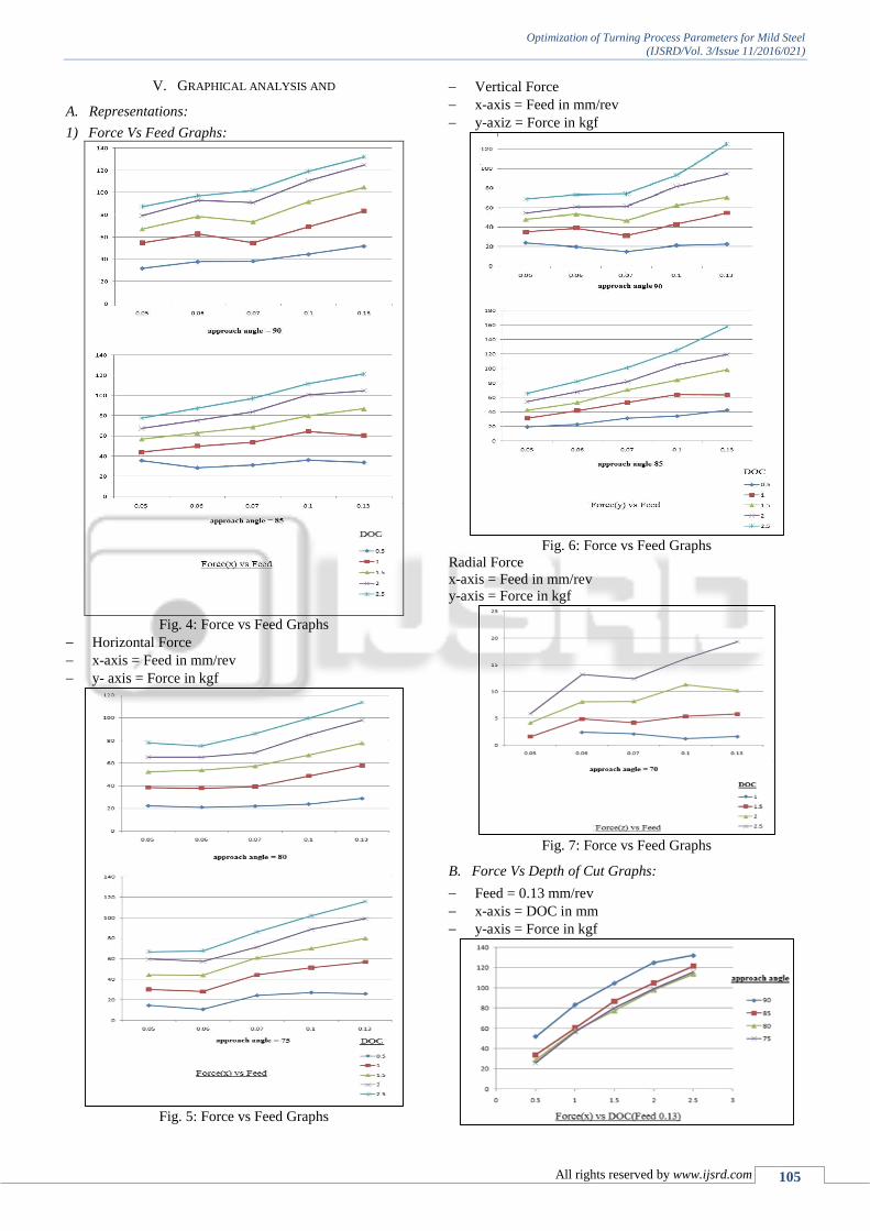
V. GRAPHICAL ANALYSIS AND
A. Representations:
1) Force Vs Feed Graphs:
Fig. 4: Force vs Feed Graphs
Horizontal Force
x-axis = Feed in mm/rev
y- axis = Force in kgf
Fig. 5: Force vs Feed Graphs
Vertical Force
x-axis = Feed in mm/rev
y-axiz = Force in kgf
Fig. 6: Force vs Feed Graphs
Radial Force
x-axis = Feed in mm/rev
y-axis = Force in kgf
Fig. 7: Force vs Feed Graphs
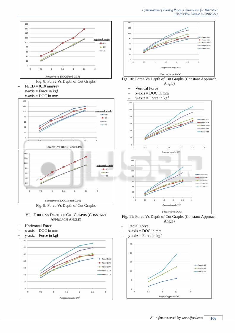
B. Force Vs Depth of Cut Graphs:
Feed = 0.13 mm/rev
x-axis = DOC in mm
y-axis = Force in kgf
Optimization of Turning Process Parameters for Mild Steel
(IJSRD/Vol. 3/Issue 11/2016/021)
All rights reserved by www.ijsrd.com 106
Fig. 8: Force Vs Depth of Cut Graphs
FEED = 0.10 mm/rev
y-axis = Force in kgf
x-axis = DOC in mm
Fig. 9: Force Vs Depth of Cut Graphs
VI. FORCE VS DEPTH OF CUT GRAPHS (CONSTANT
APPROACH ANGLE)
Horizontal Force
x-axis = DOC in mm
y-axiz = Force in kgf
Fig. 10: Force Vs Depth of Cut Graphs (Constant Approach
Angle)
Vertical Force
x-axis = DOC in mm
y-axiz = Force in kgf
Fig. 11: Force Vs Depth of Cut Graphs (Constant Approach
Angle)
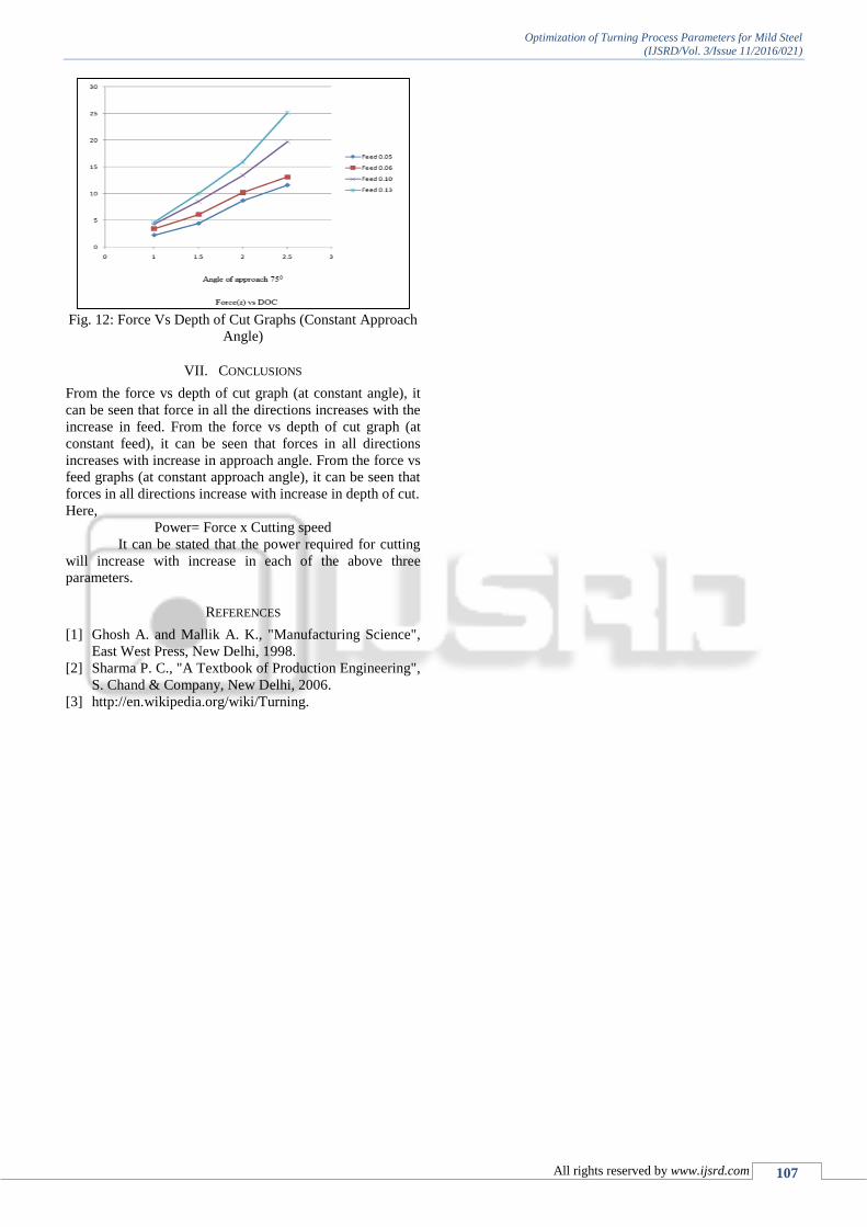
Radial Force
x-axis = DOC in mm
y-axiz = Force in kgf
Optimization of Turning Process Parameters for Mild Steel
(IJSRD/Vol. 3/Issue 11/2016/021)
All rights reserved by www.ijsrd.com 107
Fig. 12: Force Vs Depth of Cut Graphs (Constant Approach
Angle)
VII. CONCLUSIONS
From the force vs depth of cut graph (at constant angle), it
can be seen that force in all the directions increases with the
increase in feed. From the force vs depth of cut graph (at
constant feed), it can be seen that forces in all directions
increases with increase in approach angle. From the force vs
feed graphs (at constant approach angle), it can be seen that
forces in all directions increase with increase in depth of cut.
Here,
Power= Force x Cutting speed
It can be stated that the power required for cutting
will increase with increase in each of the above three
parameters.
REFERENCES
[1] Ghosh A. and Mallik A. K., "Manufacturing Science",
East West Press, New Delhi, 1998.
[2] Sharma P. C., "A Textbook of Production Engineering",
S. Chand & Company, New Delhi, 2006.
[3] http://en.wikipedia.org/wiki/Turning.


![Optimization of Cutting Parameters for surface roughness ... · Er. Sandeep Kumar et al. [4] investigated the effects of speed feed and depth of cut on MRR during CNC turning of Mild](https://static.fdocuments.net/doc/165x107/5f04b0627e708231d40f371a/optimization-of-cutting-parameters-for-surface-roughness-er-sandeep-kumar-et.jpg)

