Optimization of magnetron sputter-deposition …...Optimization of magnetron sputter-deposition...
28
Opmizaon of magnetron spuer-deposion process of thin film coangs on a moving cylindrical substrate PhD. Student Seminar 07/04/2016 Supervisors : A. Lacoste M. Mantel A. Bes C. Vachey Thomas LE COZ
Transcript of Optimization of magnetron sputter-deposition …...Optimization of magnetron sputter-deposition...
Optimization of magnetron sputter-deposition process of thin film coatings on a moving
cylindrical substratePhD. Student Seminar 07/04/2016
Supervisors : A. Lacoste M. Mantel A. Bes C. Vachey
Thomas LE COZ
Outline
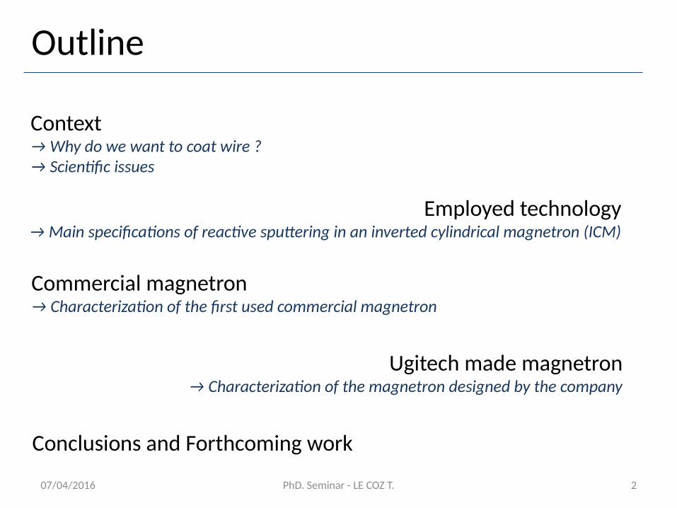
Context→ Why do we want to coat wire ?→ Scientific issues
Employed technology→ Main specifications of reactive sputtering in an inverted cylindrical magnetron (ICM)
2PhD. Seminar - LE COZ T.07/04/2016
Commercial magnetron→ Characterization of the first used commercial magnetron
Ugitech made magnetron→ Characterization of the magnetron designed by the company
Conclusions and Forthcoming work
Context
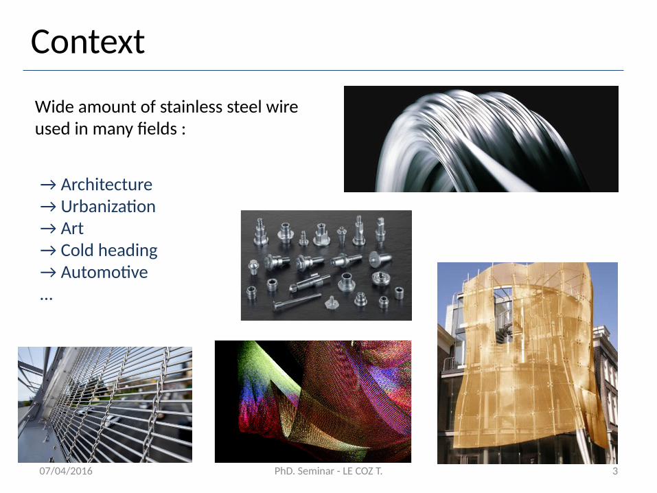
Wide amount of stainless steel wire used in many fields :
→ Architecture→ Urbanization→ Art→ Cold heading→ Automotive…
3PhD. Seminar - LE COZ T.07/04/2016
Context
4
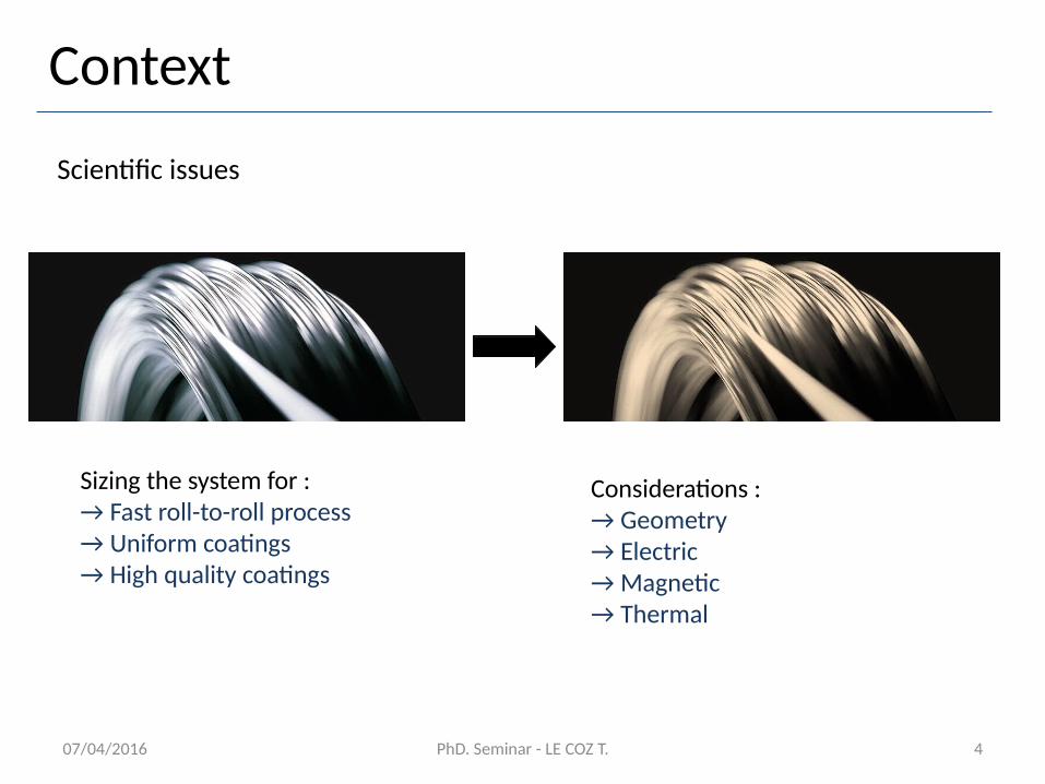
Scientific issues
Sizing the system for :→ Fast roll-to-roll process→ Uniform coatings→ High quality coatings
Considerations : → Geometry→ Electric→ Magnetic→ Thermal
PhD. Seminar - LE COZ T.07/04/2016
5
Employed technology
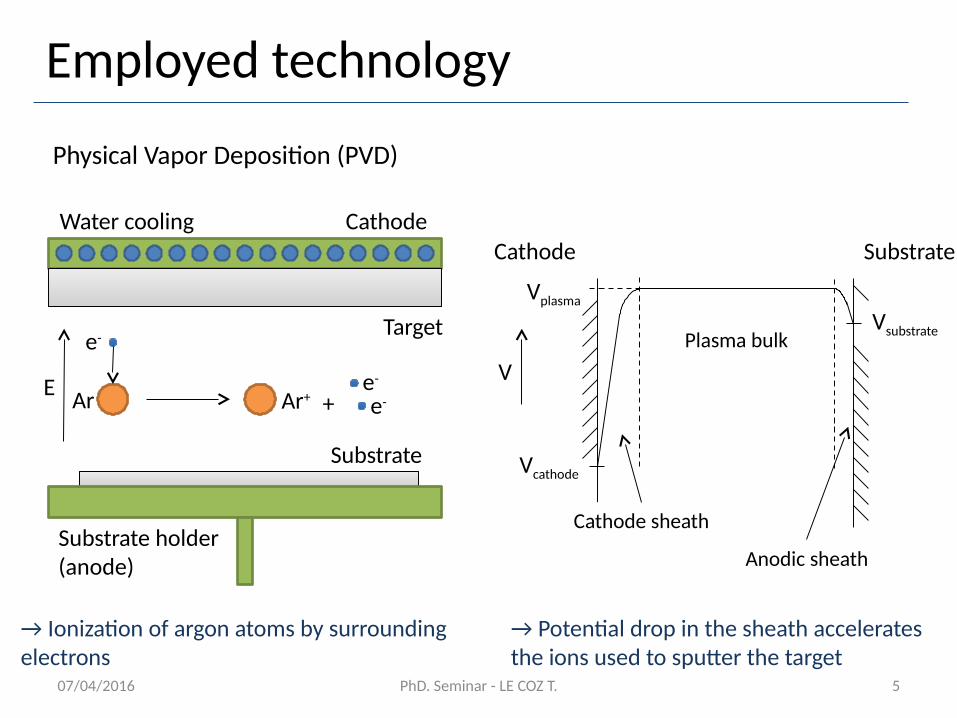
Physical Vapor Deposition (PVD)
E
Target
Substrate
CathodeWater cooling
Substrate holder (anode)
e-
Ar Ar+e-
e-+
Vsubstrate
Vcathode
Vplasma
Plasma bulk
Cathode sheath
Anodic sheath
SubstrateCathode
V
→ Ionization of argon atoms by surrounding electrons
→ Potential drop in the sheath accelerates the ions used to sputter the target
PhD. Seminar - LE COZ T.07/04/2016
6
Employed technology
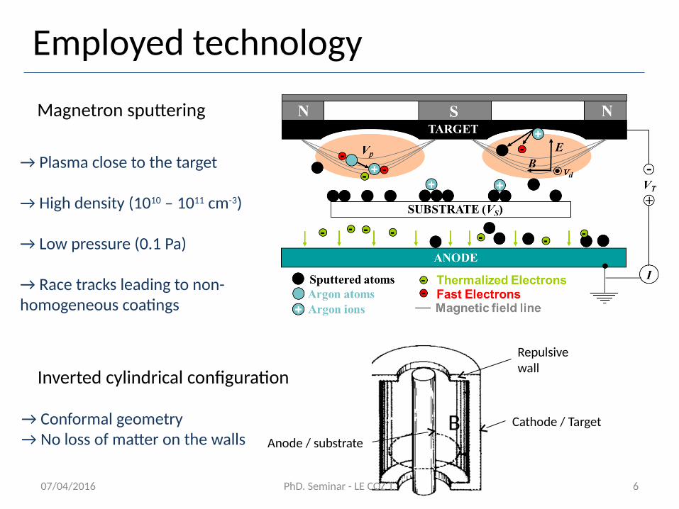
Magnetron sputtering
→ Plasma close to the target
→ High density (1010 – 1011 cm-3)
→ Low pressure (0.1 Pa)
→ Race tracks leading to non-homogeneous coatings
Inverted cylindrical configuration
B
Repulsive wall
Cathode / Target
Anode / substrate
→ Conformal geometry→ No loss of matter on the walls
PhD. Seminar - LE COZ T.07/04/2016
7
Employed technology
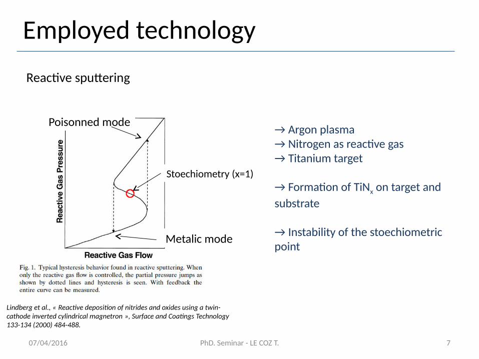
Reactive sputtering
Lindberg et al., « Reactive deposition of nitrides and oxides using a twin- cathode inverted cylindrical magnetron », Surface and Coatings Technology 133-134 (2000) 484-488.
Metalic mode
Poisonned mode→ Argon plasma→ Nitrogen as reactive gas→ Titanium target
→ Formation of TiNx on target and substrate
→ Instability of the stoechiometric point
Stoechiometry (x=1)
PhD. Seminar - LE COZ T.07/04/2016
8
Employed technology
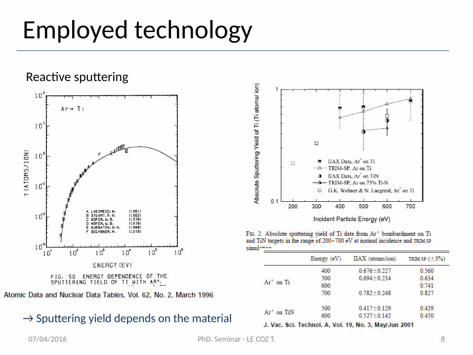
Reactive sputtering
PhD. Seminar - LE COZ T.
→ Sputtering yield depends on the material
07/04/2016
PhD. Seminar - LE COZ T. 9
Commercial magnetron
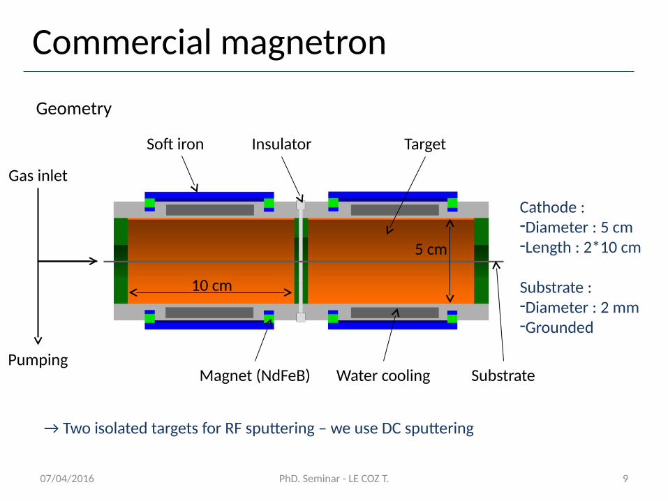
Geometry
Target
Water coolingMagnet (NdFeB) Substrate
Insulator
5 cm
10 cm
Cathode : -Diameter : 5 cm-Length : 2*10 cm
Substrate :-Diameter : 2 mm-Grounded
Gas inlet
Pumping
→ Two isolated targets for RF sputtering – we use DC sputtering
07/04/2016
Soft iron
07/04/2016 PhD. Seminar - LE COZ T. 10
Commercial magnetron
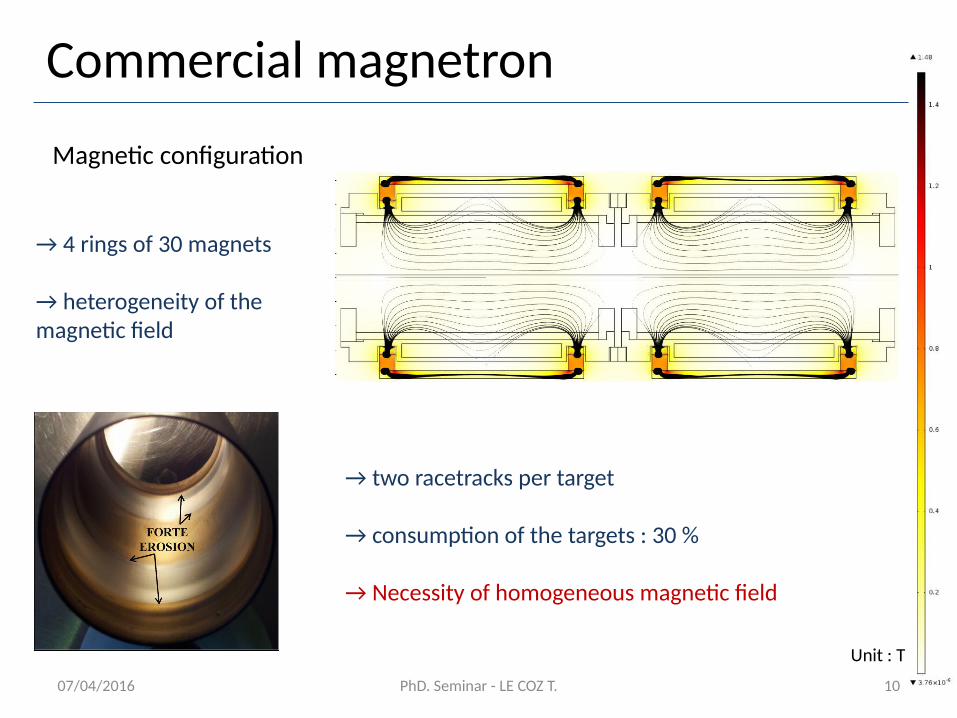
Magnetic configuration
Unit : T
→ 4 rings of 30 magnets
→ heterogeneity of the magnetic field
→ two racetracks per target
→ consumption of the targets : 30 %
→ Necessity of homogeneous magnetic field
07/04/2016 PhD. Seminar - LE COZ T. 11
Commercial magnetron
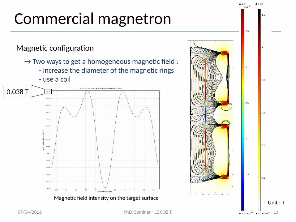
Magnetic configuration
→ Two ways to get a homogeneous magnetic field :- increase the diameter of the magnetic rings- use a coil
Unit : TMagnetic field intensity on the target surface
0.038 T
07/04/2016 PhD. Seminar - LE COZ T. 12
Commercial magnetron
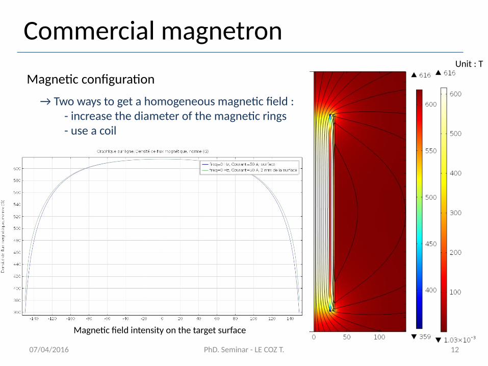
Magnetic configuration
→ Two ways to get a homogeneous magnetic field :- increase the diameter of the magnetic rings- use a coil
Unit : T
Magnetic field intensity on the target surface
07/04/2016 PhD. Seminar - LE COZ T. 13
Commercial magnetron
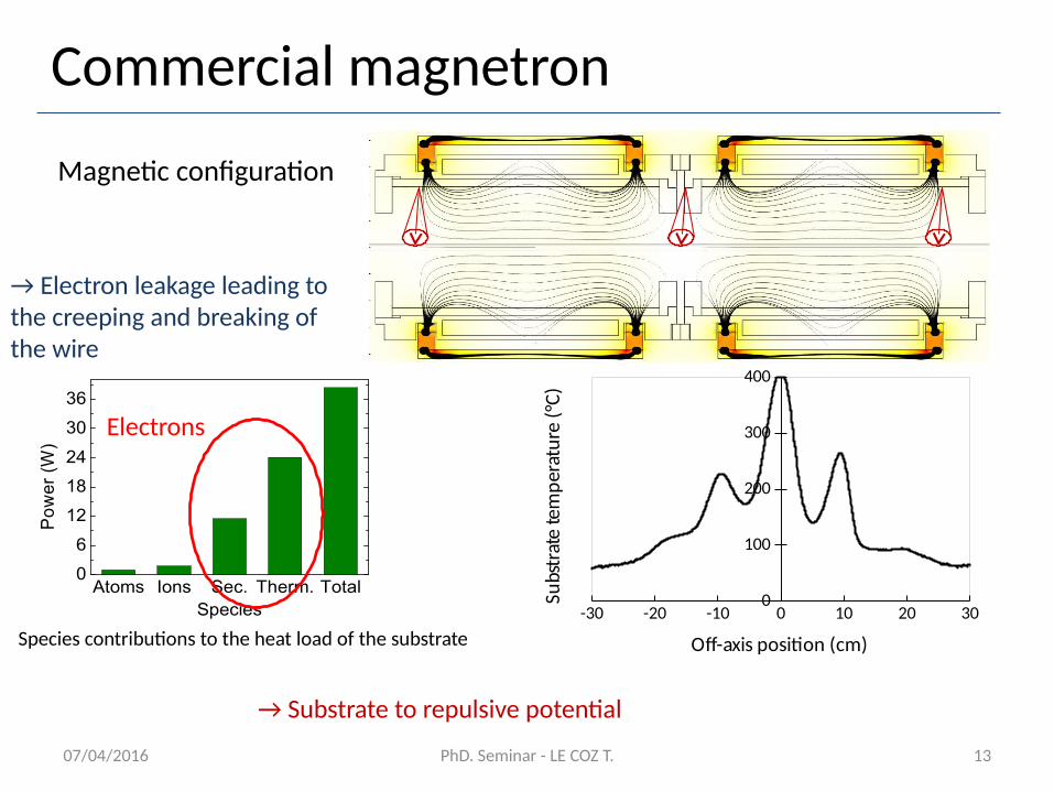
Magnetic configuration
→ Electron leakage leading to the creeping and breaking of the wire
Atoms Ions Sec. Therm. Total0
6
12
18
24
30
36
VA = 0 V
Po
wer
(W
)
Species
Electrons
-30 -20 -10 0 10 20 300
100
200
300
400
Off-axis position (cm)
Subs
trat
e te
mpe
ratu
re (°
C)
Species contributions to the heat load of the substrate
→ Substrate to repulsive potential
07/04/2016 PhD. Seminar - LE COZ T. 14
Commercial magnetron
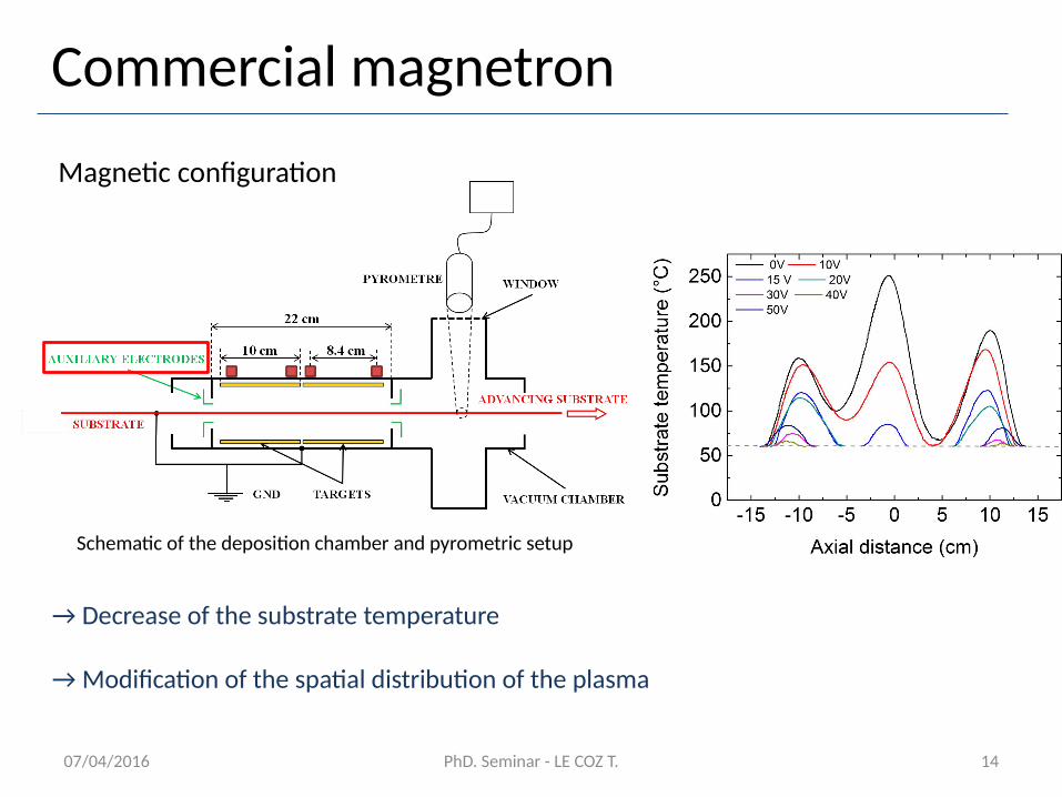
Magnetic configuration
→ Decrease of the substrate temperature
→ Modification of the spatial distribution of the plasma
Schematic of the deposition chamber and pyrometric setup
07/04/2016 PhD. Seminar - LE COZ T. 15
Commercial magnetron
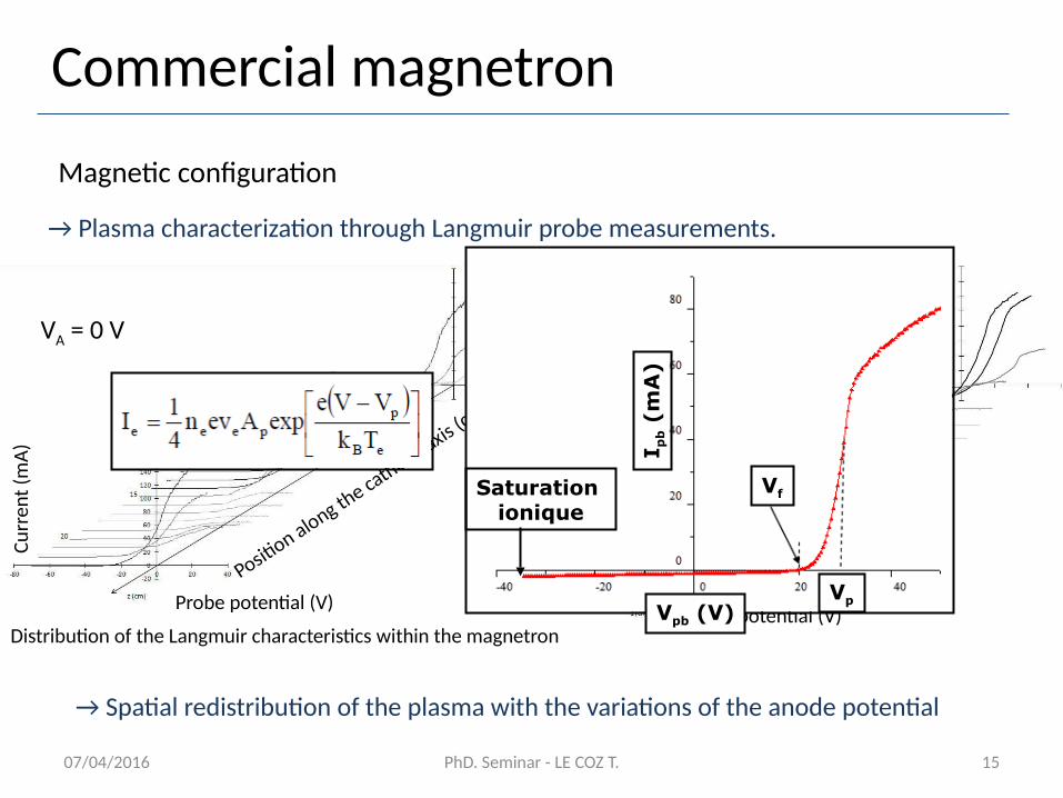
Magnetic configuration
→ Plasma characterization through Langmuir probe measurements.
VA = 0 V VA = 30 V
Distribution of the Langmuir characteristics within the magnetron
Position along the cathode axis (
cm)
Probe potential (V)
Curr
ent (
mA) Positi
on (cm)
Probe potential (V)
Curr
ent (
mA)
→ Spatial redistribution of the plasma with the variations of the anode potential
Vf
Vp
Saturation ionique
I pb (
mA
)
Vpb (V)
07/04/2016 PhD. Seminar - LE COZ T. 16
Commercial magnetron
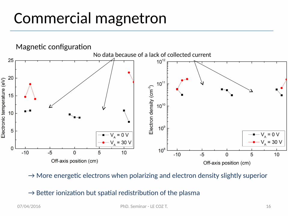
Magnetic configuration
→ More energetic electrons when polarizing and electron density slightly superior
→ Better ionization but spatial redistribution of the plasma
No data because of a lack of collected current
07/04/2016 PhD. Seminar - LE COZ T. 17
Commercial magnetron
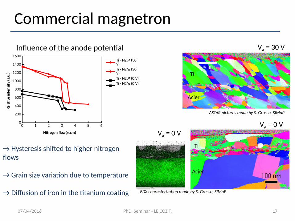
Influence of the anode potential
C Ti
Acier
Acier
Ti
VA = 0 V
→ Hysteresis shifted to higher nitrogen flows
→ Grain size variation due to temperature
→ Diffusion of iron in the titanium coating
ASTAR pictures made by S. Grosso, SIMaP
VA = 0 V
EDX characterization made by S. Grosso, SIMaP
VA = 30 V
0 1 2 3 4 5 60
200
400
600
800
1000
1200
1400
1600Ti - N2↗ (30 V)Ti - N2↘ (30 V)Ti - N2↗ (0 V)Ti - N2↘ (0 V)
Nitrogen flow(sccm)
Relat
ve in
tens
ity (a
.u.)
07/04/2016 PhD. Seminar - LE COZ T. 18
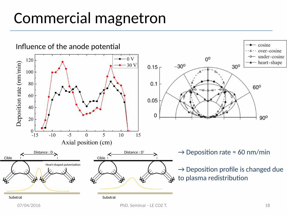
→ Deposition rate ≈ 60 nm/min
→ Deposition profile is changed due to plasma redistribution
Cible
Substrat
Heart-shaped pulverization
Distance : DCible
Substrat
Distance : D’
Commercial magnetron
Influence of the anode potential
07/04/2016 PhD. Seminar - LE COZ T. 19
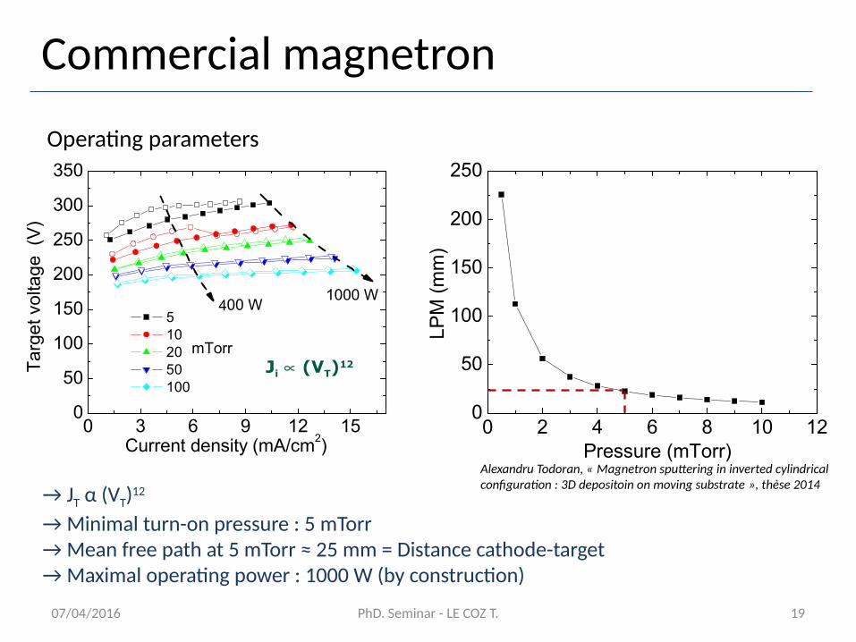
0 3 6 9 12 150
50
100
150
200
250
300
350
mTorr
500 W 5 10 20 50 100
Ta
rge
t vo
ltag
e (
V)
Current density (mA/cm2)
1000 W
Ji (VT)12
4
0 2 4 6 8 10 120
50
100
150
200
250
LP
M (
mm
)Pressure (mTorr)
→ JT α (VT)12
→ Minimal turn-on pressure : 5 mTorr→ Mean free path at 5 mTorr ≈ 25 mm = Distance cathode-target→ Maximal operating power : 1000 W (by construction)
Alexandru Todoran, « Magnetron sputtering in inverted cylindrical configuration : 3D depositoin on moving substrate », thèse 2014
Commercial magnetron
Operating parameters
0 1 2 3 4 5 6225230235240245250255260265270
N2↗ (30 V)
Nitrogen flow (sccm)
Cath
ode
pote
ntial
(V)
07/04/2016 PhD. Seminar - LE COZ T. 20
Commercial magnetron
Operating parameters
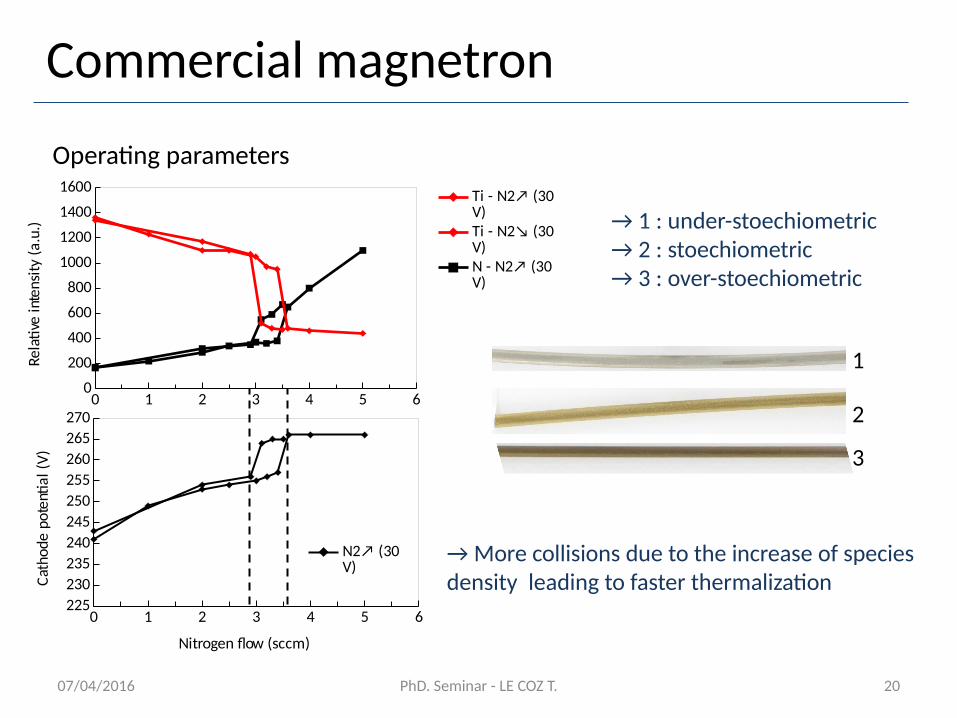
1 2 3
1
3
2
→ More collisions due to the increase of species density leading to faster thermalization
→ 1 : under-stoechiometric → 2 : stoechiometric→ 3 : over-stoechiometric
0 1 2 3 4 5 60
200
400
600
800
1000
1200
1400
1600 Ti - N2↗ (30 V)Ti - N2↘ (30 V)N - N2↗ (30 V)
Rela
tive
inte
nsity
(a.u
.)
07/04/2016 PhD. Seminar - LE COZ T. 21
Commercial magnetron
Intermediate conclusion
→ Necessity of homogeneous magnetic field
→ Control of the substrate temperature by polarizing auxiliary electrodes …
→ … which influences the plasma distribution within the reaction chamber
→ Low deposition rate
→ Power input limited
→ Unstable conditions for stoechiometric coatings
07/04/2016 PhD. Seminar - LE COZ T. 22
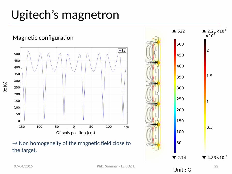
Ugitech’s magnetron
Magnetic configuration
Unit : G
→ Non homogeneity of the magnetic field close to the target.
Off-axis position (cm)
Bz (G
)
150
07/04/2016 PhD. Seminar - LE COZ T. 23
Ugitech’s magnetron
Magnetic configuration
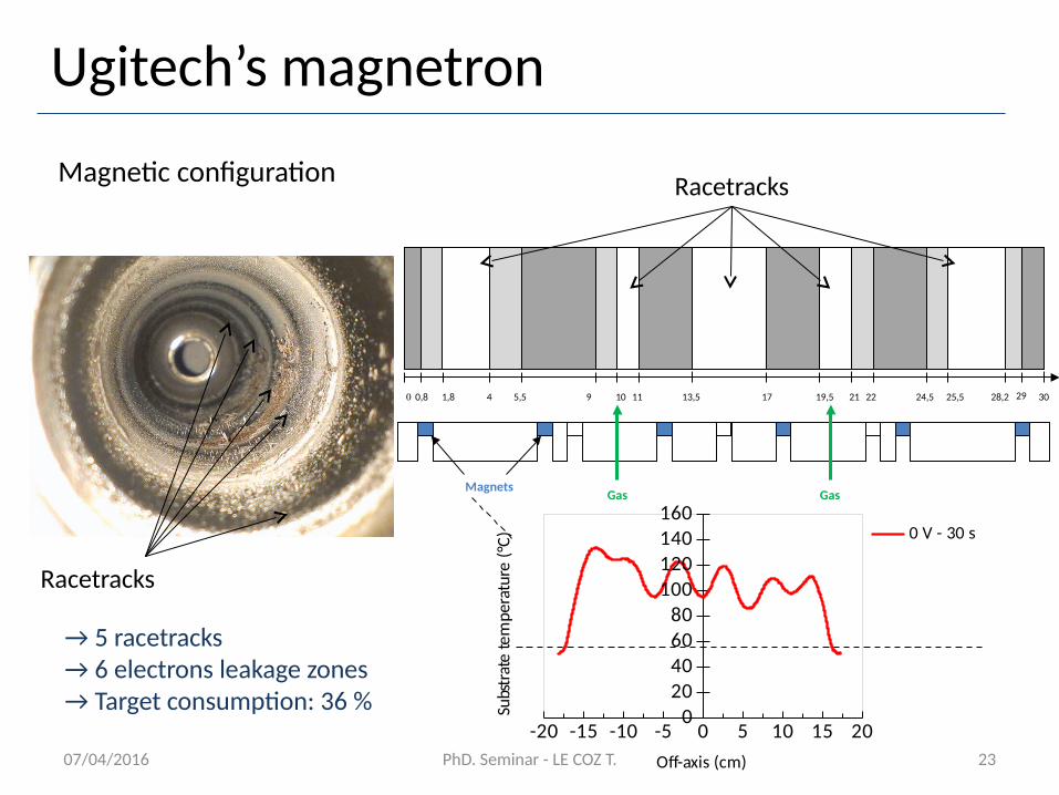
0 0,8 1,8 4 5,5 9 10 11 13,5 17 19,5 21 22 24,5 25,5 28,2 29 30
Gas GasMagnets
Racetracks
Racetracks
-20 -15 -10 -5 0 5 10 15 200
20406080
100120140160
0 V - 30 s
Off-axis (cm)
Subs
trat
e te
mpe
ratu
re (°
C)
→ 5 racetracks → 6 electrons leakage zones→ Target consumption: 36 %
07/04/2016 PhD. Seminar - LE COZ T. 24
Ugitech’s magnetron
Operating parameters
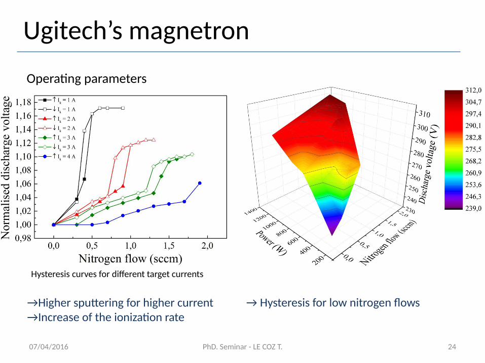
→Higher sputtering for higher current→Increase of the ionization rate
Hysteresis curves for different target currents
→ Hysteresis for low nitrogen flows
07/04/2016 PhD. Seminar - LE COZ T. 25
Ugitech’s magnetron
Operating parameters
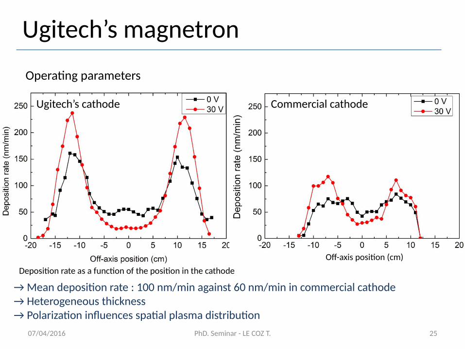
→ Mean deposition rate : 100 nm/min against 60 nm/min in commercial cathode→ Heterogeneous thickness→ Polarization influences spatial plasma distribution
Deposition rate as a function of the position in the cathode
Commercial cathodeUgitech’s cathode
Off-axis position (cm)
07/04/2016 PhD. Seminar - LE COZ T. 26
Ugitech’s magnetron
Titanium nitride coatings
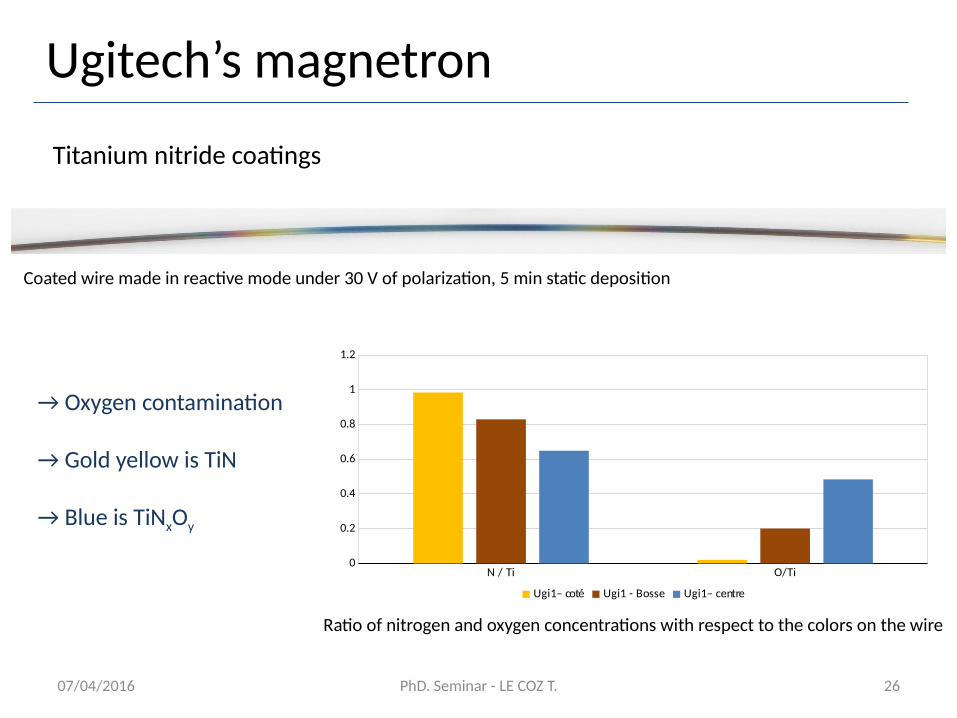
→ Oxygen contamination
→ Gold yellow is TiN
→ Blue is TiNxOy
N / Ti O/Ti0
0.2
0.4
0.6
0.8
1
1.2
Ugi1– coté Ugi1 - Bosse Ugi1– centre
Ratio of nitrogen and oxygen concentrations with respect to the colors on the wire
Coated wire made in reactive mode under 30 V of polarization, 5 min static deposition
07/04/2016 PhD. Seminar - LE COZ T. 27
Ugitech’s magnetron
Intermediate conclusions
→ Necessity of homogeneous magnetic field
→ Control of the substrate temperature by polarizing auxiliary electrodes …
→ … which influences the plasma distribution within the reaction chamber
→ Deposition rate greater than for the commercial cathode
→ Unknown limit of power input – grater than that for the commercial cathode
→ Unstable conditions for stoechiometric coatings
→ Oxygen contamination – Unknown origin
07/04/2016 PhD. Seminar - LE COZ T. 28
Forthcoming work
→ Sizing of a coil
→ Study the influence of the diameter of the targets
→ Modeling of the sputtering process
→ Modeling of the gas dynamics
→ Find the origin of the oxygen contamination
→ Ultimately design a new optimized magnetron