Optimization of isothermal transformation period for ...
19
313 Metallurgy and Foundry Engineering – Vol. 43, 2017, No. 4, pp. 313–331 http://dx.doi.org/10.7494/mafe.2017.43.4.313 Prashant Parhad, Ajay Likhite, Jatin Bhatt, Dilip Peshwe 1 Optimization of isothermal transformation period for austempered ductile iron Optymalizacja okresu przemiany izotermalnej podczas hartowania izotermalnego żeliwa ciągliwego perlitycznego Abstract The present paper examines and compares the influence of austempering parameters such as temperature and time on the isothermal transformation and microstructural changes of ductile iron. To identify the compositional and structural changes during an isothermal transformation, a very wide austempering period is chosen at a transformation temperature for the precise de- termination of the process window. XRD, optical, and scanning electron microscopic techniques are exploited to identify and analyze the changes in the austempered structure, at austemper- ing temperatures of 250°C and 400°C. The various structural parameters like austenite volume fraction (V g , its carbon content (C g ), lattice parameter, and the average cell size of the ferrite are ascertained. Electron backscattered diffraction (EBSD) analysis is used to identify the carbide pre- cipitation obtained due to the austempering Stage-II reaction. It is noticed that, at the end of the austempering Stage-II reaction, there is a significant reduction in the volume fraction of stabilized austenite and it’s carbon content, as the microstructure at this stage not only contains ausferrite but also additional precipitated iron carbides. With an increase in austempering time, the aus- tenite and ferrite volume fraction increase until the austenite becomes stabilized with sufficient carbon. The increase in the lattice parameter of the austenite during austempering corresponds to the rise in carbon content within the austenite. A rise in the austempering temperature leads to a reduction in the volume fraction of the ferrite and an increase in the stabilized austenite volume fraction. The optimum isothermal transformation period for austempered ductile iron is established, based on the period during which the maximum content of the austenite volume fraction, its carbon, the lattice parameter, and the average cell size of the ferrite are maintained. Keywords: ADI, stabilized austenite, process window, EBSD, austempering Streszczenie W pracy przedstawiono badania dotyczące wpływu parametrów hartowania izotermicznego takich jak temperatura i czas na izotermiczną transformację i zmiany mikrostrukturalne żeliwa Prashant Parhad Associate Professor: Kavikulguru Institute of Technology and Science, Department of Mechanical Engineering, Ramtek, India, Ajay Likhite Associate Professor, Jatin Bhatt Associate Professor, Dilip Peshwe Profes- sor: Visvesvaraya National Institute of Technology, Department of Metallurgy and Materials Engineering, Nagpur, India; [email protected]
Transcript of Optimization of isothermal transformation period for ...

313
Metallurgy and Foundry Engineering – Vol. 43, 2017, No. 4, pp. 313–331http://dx.doi.org/10.7494/mafe.2017.43.4.313
Prashant Parhad, Ajay Likhite, Jatin Bhatt, Dilip Peshwe1
Optimization of isothermal transformation period for austempered ductile iron
Optymalizacja okresu przemiany izotermalnej podczas hartowania izotermalnego żeliwa ciągliwego perlitycznego
AbstractThe present paper examines and compares the influence of austempering parameters such as temperature and time on the isothermal transformation and microstructural changes of ductile iron. To identify the compositional and structural changes during an isothermal transformation, a very wide austempering period is chosen at a transformation temperature for the precise de-termination of the process window. XRD, optical, and scanning electron microscopic techniques are exploited to identify and analyze the changes in the austempered structure, at austemper-ing temperatures of 250°C and 400°C. The various structural parameters like austenite volume fraction (Vg, its carbon content (Cg), lattice parameter, and the average cell size of the ferrite are ascertained. Electron backscattered diffraction (EBSD) analysis is used to identify the carbide pre-cipitation obtained due to the austempering Stage-II reaction. It is noticed that, at the end of the austempering Stage-II reaction, there is a significant reduction in the volume fraction of stabilized austenite and it’s carbon content, as the microstructure at this stage not only contains ausferrite but also additional precipitated iron carbides. With an increase in austempering time, the aus-tenite and ferrite volume fraction increase until the austenite becomes stabilized with sufficient carbon. The increase in the lattice parameter of the austenite during austempering corresponds to the rise in carbon content within the austenite. A rise in the austempering temperature leads to a reduction in the volume fraction of the ferrite and an increase in the stabilized austenite volume fraction. The optimum isothermal transformation period for austempered ductile iron is established, based on the period during which the maximum content of the austenite volume fraction, its carbon, the lattice parameter, and the average cell size of the ferrite are maintained.
Keywords: ADI, stabilized austenite, process window, EBSD, austempering
StreszczenieW pracy przedstawiono badania dotyczące wpływu parametrów hartowania izotermicznego takich jak temperatura i czas na izotermiczną transformację i zmiany mikrostrukturalne żeliwa
Prashant Parhad Associate Professor: Kavikulguru Institute of Technology and Science, Department of Mechanical Engineering, Ramtek, India, Ajay Likhite Associate Professor, Jatin Bhatt Associate Professor, Dilip Peshwe Profes-sor: Visvesvaraya National Institute of Technology, Department of Metallurgy and Materials Engineering, Nagpur, India; [email protected]

314
sferoidalnego. W celu określenia zmian strukturalnych i składu chemicznego podczas przemiany izotermalnej został dobrany bardzo szeroki okres hartowania izotermalnego, co pozwoliło na pre-cyzyjne określenie warunków procesu. Zastosowano techniki takie jak dyfrakcja promieniowania rentgenowskiego (XRD), mikroskopia świetlna i skaningowa mikroskopia elektronowa, aby ziden-tyfikować i przeanalizować zmiany strukturalne po hartowaniu w temperaturach 250°C i 400°C. Określono różne czynniki strukturalne, takie jak udział objętościowy austenitu (Vg), zawartość węgla w austenicie (Cg), stała sieciowa oraz średnia wielkość komórki elementarnej ferrytu. Dy-frakcję elektronów wstecznie rozproszonych (EBSD) zastosowano do zidentyfikowania wydzieleń węglików powstałych wskutek reakcji drugiego etapu podczas hartowania izotermalnego. Nie zauważono, aby z końcem reakcji drugiego etapu hartowania izotermalnego nastąpił widoczny spadek udziału objętościowego ustabilizowanego austenitu i zawartości w nim węgla, ponieważ mikrostruktura na tym etapie nie tylko zawiera ausferryt, lecz również wydzielenia węglików że-laza. Wraz z wydłużeniem czasu hartowania udział objętościowy austenitu i ferrytu wzrasta aż do momentu, kiedy austenit zostanie ustabilizowany odpowiednią ilością węgla. Zwiększenie sta-łych sieciowych austenitu w trakcie hartowania izotermalnego prowadzi do zmniejszenia udziału objętościowego żelaza i wzrostu udziału ustabilizowanego austenitu. Optymalny okres transfor-macji izotermalnej hartowanego żelaza sferoidalnego został określony na podstawie okresu, pod-czas którego maksymalna zawartość udziału objętościowego austenitu, zawartego w nim węgla, stałej sieciowej i średniej wielkości komórki elementarnej ferrytu była utrzymana.
Słowa kluczowe: ADI, stabilizowany austenit, warunki procesu, EBSD, hartowanie izotermalne
1. Introduction
Austempered ductile iron (usually known as ‘ADI’) has gained recognition among pro-ducers as an important structural material. Though ADI is a well-known material, con-tinuous research has been carried out to improve its properties and to understand the mechanism that governs ADI formation [1, 2]. ADI is produced by subjecting ductile iron (DI) to austempering heat treatment that involves austenitization and isothermal transformation in the bainitic temperature region, followed by air-cooling. The subse-quent microstructure of the ADI matrix mainly consists of acicular ferrite and the carbon stabilized austenite. During the isothermal transformation, an alloy passes through three segments. In the first segment, the nucleation of the ferrite takes place at the graphite/austenite interface. As the solubility of the carbon in ferrite is very low, it rejects the car-bon in the surrounding austenite. Thus, the growth of ferrite causes an enrichment of carbon in the austenite with the passage of austempering time. This leads to the gradual stabilization of austenite so that it will exist in the structure even after cooling. But, due to short austempering time, a very small amount of carbon diffusion takes place in the austenite in this stage; hence, the stability of the austenite is not sufficient, as it gets transformed to martensite during cooling). In the second segment, the concentration of carbon in the austenite gradually increases to its maximum equilibrium level, as more

315
and more carbon is rejected from the ferrite to the surrounding austenite, causing its thermal stability; by which, the martensitic transformation is avoided during the cooling to room temperature. This segment is characterized by the presence of a unique ausfer-ritic structure; in general, this is believed to be the best structure that is responsible for the attribution of remarkable properties in the ADI. In the third and last segment, the amount of the stabilized austenite starts to decline because of its further transformation into the ferrite and iron carbide [3]. Hence, depending upon the isothermal transforma-tion time, some amount of martensite or number of carbides can appear, resulting in a degradation of the mechanical properties [4]. The combination of plasticity and tough-ness are the most-desirable properties required in wide applications, such as parts in automotive, construction, agriculture, and railroad components worldwide. In ADI, these properties are obtained when the austenite volume fraction, its carbon content, and lattice parameter are at their maximum levels. This coincides with the second segment of the isothermal transformation period and is recognized as the “optimum isothermal transformation period” [5].
Rundman reported [6] that reducing the austenitization temperature from 927°C to 871°C lowers the matrix carbon content by 0.16 wt.%, which results in an increase in the rate of the ausferrite reaction by about a factor of two. Tanaka and Kage [7] explained the thermodynamic reason behind this increase in the reaction rate. However, once the aus-tenitization temperature is selected, it is the austempering temperature and time that decides the final microstructure be obtained at the end of the heat-treatment process. Therefore, an understanding of the relationship between the austempering transforma-tion and the resultant microstructure developed under variable austempering conditions is essential to appreciate and optimize the austempering parameters (such as tempera-ture and time). The transformation response of DI during austempering depends on the very complex interaction between ductile iron chemistry, austempering temperature, and time. These factors affect both the nucleation of the Stage-I reaction and austenite decomposition during the Stage-II reaction.
ADI is identified as a sustainable green alternative materia; l hence, understanding the exact mechanism of its ausferritic structure and optimizing the best combinations of the heat treatment parameters will boost the use this perspective material for vari-ous applications. Though adequate information and data is available now in the process-ing window of ADI, the overall work has been initiated for the in-depth understanding of ausferritic transformations in ADI. Hence, the aim of this work is to recognize the exact mechanism of ausferrite transformation and also determine the optimum range of the transformation period. The emphasis is given on the co-relationship between the aus-tenite volume fraction, its carbon content, the lattice parameter, and the average cell size of the ferrite obtained by subjecting DI to lower and higher austempering temperatures of 250°C and 400°C for varying durations.

316
2. Experimental
The chemical composition of ductile iron used for this investigation is given in Table 1.
Table 1. Chemical composition [wt.%] of ductile iron
Grade C.E %C %Si %Mn %P %S %Cr %Ni %Cu %Mg %Fe
DI (C0) 4.23 3.53 2.50 0.44 0.045 0.010 0.037 0.008 0.56 0.050 balance
The DI specimens of the stated composition are then subjected to austempering heat treatment (as shown in Figure 1).
To investigate the structural and compositional changes during the isothermal transformation, a wide range of austempering durations (particularly at 250°C, TA = 1 h to 8 h at an interval of 1 h, and at 400°C, TA = 2 h to 10 h at an interval of 2 h) were cho-sen. After holding the specimens for the specified duration, they are air-cooled from the austempering temperature to room temperature.
Fig. 1. Schematic of austempering treatment
The metallographic samples were prepared from test specimens after heat treat-ment to investigate the changes in microstructure (the complete details of the sample preparation have been described in our previous work) [8]. The X-ray diffraction (XRD) technique was used to determine the amount of carbon-stabilized austenite and its car-bon content. To compute the carbon stabilized austenite content of the ADI, a simple method described by Senczyk [9] and an equation proposed by Aranzabal [10] for calcu-lating the carbon dissolved in austenite is used. Then, the austenite lattice parameter (ag) is determined by the well-known equation stated by Cullity [11], while the average size of the ferrite cell is calculated by using Equation (1) [11].
900
250
AustemperingAustenitization
1 2 3 4 5 6 7 8 10Time (Hr)
Tem
pera
ture
(o C)
1Hr400
Air cooling
10Hr
6Hr
4Hr
2Hr
8Hr
900
250
AustemperingAustenitization
1 2 3 4 5 6 7 8 10
Time (Hr)
Tem
pera
ture
(o C)
1Hr400
Air cooling
10Hr
6Hr
4Hr
2Hr
8Hr
317
d = 0 9.cos
λβ θ
(1)
where: d – average particle size of ferrite [nm], l – wavelength [nm], β – diffraction line broadening, measured in the middle of its maximal inten-
sity [rad], θ – the angle of the interference line determined from the diffraction pattern in [°].
Vickers hardness test is used to measure the bulk hardness of the heat-treated speci-men. Details of the sample preparation, measurement conditions (and determination of carbon content), lattice parameter, and volume fraction of the austenite have all been described in previous works [8].
3. Results and discussion
The austempering transformation in DI is represented by a two-stage reaction; one with austenite (g) decomposing to acicular ferrite (a) and high carbon austenite (gHC) (i.e., g → a + gHC) followed by two, further high carbon austenite decomposition to ferrite and carbide (i.e., gHC → a + carbides).
3.1. Austempering temperature and time
To develop the desired microstructure in ADI, the proper selection of austempering tem-perature is an important step. The ferrite and carbon-enriched austenite are the typical constituents of DI heat treated at a higher temperature [12]. If the temperature is low, then it retards the rejection of carbon from the ferrite, therefore resulting in the forma-tion of transitional carbides within the ferrite [13]. Hence, at a lower temperature, the structure consists of small amounts of austenite ≤10%, while at a high temperature, it can be as high as 40%. The correct austempering time should result in structures free from martensite (characteristics of a too-short holding time) and precipitated carbides (characteristics of a too-long holding time) as the results in degradation of mechanical properties [14].
DI austempered at 250°C
The as-cast microstructure of the ductile iron consists of graphite nodules embedded in ferritic envelops with the pearlitic matrix as shown in Figure 2a, while Figure 2b illus-trates the microstructure in an unetched condition revealing the uniform distribution of graphite nodules dispersed throughout the matrix. A nodule count of 512 nods/mm2 is obtained for a cylindrical specimen of 20 mm in diameter.

318
a) b)
Fig. 2. As-cast microstructure of ductile iron: a) graphite nodules embedded in ferritic envelope with pearlitic matrix [8]; b) graphite nodules uniformly distributed in matrix (unetched condition)
Fig. 3. Effect of austempering time on average cell size of ferrite austempered at 250°C and 400°C
The austempering temperature and time influences both the transformation kinet-ics as well as the mechanism of transformation; hence, their response is extremely com-plicated. At the lower temperature, the nucleation rate was high, but the diffusion and growth rates were low; therefore, a significant amount of ferrite nucleation took place,
250°C
400°C
319
and finer cell sizes of the ferrite were accordingly obtained. This effect is evident in Fig-ure 3, which shows the influence of austempering time on the average cell size of ferrite austempered at 250°C and 400°C. The cell size of the ferrite obtained in DI austempered at 250°C (blue dots) is much smaller as compared to 400°C.
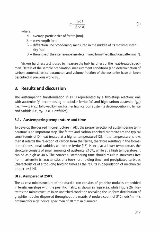
For DI austempered at 250°C, the acicular ferrite needles begin to nucleate in the first segment of austempering, primarily at the graphite/austenite interface (as these are potent sites for nucleation and growth). This effect is evident in optical image Figure 4a, while the acicular morphology of ferrite is revealed in SEM image Figure 4b. The calculat-ed values of the austenite lattice parameter, its carbon concentration, and the amounts of stabilized austenite as well as ferrite at changing austempering durations are reported in Table 2.
a) b)
Fig. 4. Microstructure of DI -250-1 h (etched with 2% Nital): a) optical microscope – black arrow indicating growth of ferrite on graphite-austenite interface; b) SEM image
The effect of the austempering duration on (a) the lattice parameter and carbon content of austenite, (b) the volume fraction of C-stabilized austenite, and (c) the average cell size of the ferrite is revealed in Figures 5–7, respectively. The entire mechanism of this austempering transformation is discussed in detail in research paper [8].
It was observed that, beyond 3 h of isothermal transformation up to a 6 h duration:a) the lattice parameter and carbon content of austenite essentially remain unvarying
(i.e., ag = 6.234 ± 0.006 and %C = 1.71 ± 0.125);b) the content of C-stabilized austenite reduces marginally but stays steady in essence
(i.e., %C-stabilized austenite = 19.94 ± 2.95);c) similarly, the average cell size of ferrite = 18.34 ± 2.10 nm; d) the hardness of the specimens remain almost stable (HV10 = 596 ± 25) in this seg-
ment.
face

320
Tabl
e 2.
Sum
mar
y of
pro
pert
ies a
nd X
RD a
naly
sis o
f DI 2
50 a
nd D
I400
Aus
t.
tim
e [h
r]%
C in
Vg
a (g
)Å%
R. A
uste
n-it
eCe
ll si
ze o
f a
[nm
]H
ardn
ess
(HV
10)
% F
erri
teM
arte
nsit
eIr
on c
arbi
de
250°
C40
0°C
250°
C40
0°C
250°
C40
0°C
250°
C40
0°C
250°
C40
0°C
250°
C40
0°C
250°
C40
0°C
250°
C40
0°C
11.
14*
3.6
*4.
9*
11.2
6*
523
*83
.1*
133
*lo
w*
21.
622.
033.
623.
647.
2219
.34
16.2
824
.450
648
280
.78
68.6
612
917
7lo
wtr
aces
31.
84*
3.63
*22
.89
*36
.57
*46
7*
65.1
1*
108
*lo
w*
41.
812.
063.
633.
6417
.46
23.7
720
.93
29.4
257
345
570
.54
64.2
3tr
aces
128
781
trac
es
517
8*
3.63
*17
.37
*10
.45
*59
3*
70.6
3*
trac
es*
985
*
61.
592.
183.
623.
6416
.99
27.0
816
.24
36.6
562
243
271
.01
60.9
2tr
aces
trac
es10
07tr
aces
71.
531.
833.
613.
638
11.7
310
.97
16.2
916
.27
490
469
76.2
777
.03
trac
estr
aces
1465
700
8*
1.72
*3.
62*
10.7
8*
36.7
1*
491
*77
.22
**
*77
5
10*
1.68
*3.
62*
10.2
4*
29.3
9*
445
*77
.76
**
*73
1
* sp
ecim
en n
ot p
repa
red
and,
hen
ce, n
ot a
naly
zed

321
Fig. 5. Dependence of austenite lattice parameter and ‘C’ content in austenite on austempering transformation time [8]
Fig. 6. Dependence of % of carbon-stabilized Austenite on austempering transformation time [8]
Fig. 7. Effect of transformation duration on at 250°C average particle size of ferrite

322
This duration of 3–6 h is the time between the completion of Stage-I and onset of the Stage-II reaction, and it is recognized as the optimum duration of the process win-dow. This process window is characterized by the retention of the maximum fraction of C-stabilized austenite and high carbon content in the ADI matrix and is identified as the second segment of the isothermal transformation period.
In many research papers, the bad effect of precipitation of the iron carbide in the ausferritic matrix due to extended duration was discussed. However, very few research-ers have provided physical proof of the existence of it. In this investigation, iron car-bide precipitates are detected, probably for the first time by the EBSD technique. Very short peaks of iron carbide are detected in the XRD analysis at 2θ values of 44.53° and 44.95° corresponding to planes (220) and (031), respectively, at transformation durations of 5 h to 7 h (please refer to Figure 8). For further confirmation on whether or not the carbides are formed, the EBSD analysis of DI austempered at 250°C for 7 h is studied.
Fig. 8. XRD patterns of the specimen austempered
EBSD analysis disclosed that the fine precipitation of iron carbides took place at the ferrite/austenite interface (Fig. 9, yellow dots). The microstructure obtained at 7 h of iso-thermal holding comprises a low volume fraction of austenite (11.73 wt.%) and high

323
content of ferrite (73.27 wt.%) as well as carbides (5.9 wt.%). Lengthening duration again continues the dissociation of C-stabilized austenite; as a result, the microstructure of the specimen at 8 h shows a significant amount of ferrite and number of iron carbides. In the XRD pattern, the presence of austenite is not detected; hence, the volume fraction of austenite, its carbon content and accordingly its lattice parameter is not determined for the DI 250 8 h specimen. During the transformation of austenite into ferrite, local supersaturation of the g solid solution with carbon happens, which is caused by the con-tinuous diffusion of carbon atoms into the non-transformed austenite, resulting in the precipitation of the iron carbide. The results of the ADI matrix investigated at the dif-ferent austempering times agree well with the observations of earlier research works [5, 7, 15]. It has been found that ferrite grows by displacive transformation; however, car-bon atoms diffuse into the surrounding austenite or precipitate as carbides shortly once the growth is arrested [16, 17]. The precipitation of carbides locally reduces the carbon content of the parent austenite and increases the driving force for further ferrite growth.
Fig. 9. Showing Iron carbide precipitate (yellow dots) at ferrite /austenite interface [8]
Thus, the precipitation of cementite results in a rise in the volume fraction of the acicular ferrite. The growth of the ferrite is diffusionless; however, any excess carbon in the supersaturated ferrite soon partitions into the residual austenite or precipitates with-in the ferrite in the form of carbides [18, 19]. It was also identified that the average cell size of the ferrite also starts reducing very significantly starting at the seventh hour of the
Iron carbide

324
holding period. This effect is attributed to the start of the Stage-II reaction that results in the dissociation of ghc into ferrite and carbides.
The volume fraction remains nearly constant up to 6 h; further on, it starts to decline due to the start of carbide precipitation. Hence, the transformation interval of 6 h is the limit between the second and third transformation segments. Therefore, it is confirmed that, during the isothermal transformation of the DI in the first segment, the volume frac-tion of carbon stabilized the austenite, and the average cell size of the ferrite increases as the isothermal reaction proceeds to 3 h. In the second segment, it reaches its maxi-mum and then remains approximately constant (3–6 h). Eventually at the third segment, the volume fraction of the austenite as well as the ferrite cell size reduces due to the dissociation of C-stabilized austenite into ferrite and iron carbide (7–8 h). Hence, it is concluded that the range of the isothermal transformation duration is divided into three distinct segments, and the optimum isothermal duration for DI austempered at 250°C is obtained during the second segment (which ranges from 3 h to 6 h).
DI austempered at 400°C
At a higher temperature, the nucleation rate is slow, but the diffusion rate is fast; accord-ingly, fewer ferrite cells nucleate and grow fairly, leading to a coarser cell size. This effect is evident in Figure 3. As already mentioned, the austempering transformation begins with the nucleation of ferrite, and its growth, preferentially at the graphite nodule which is the potential site of nucleation. The findings given in Table 2 as well as the graphs shown in Figure 10 point out that, at 2 h, the concentration of carbon in the austenite is 2.025 wt.%, and the corresponding lattice parameter size is 3.637 Å.
Fig. 10. Dependence of austenite lattice parameter size and ‘C’ content in austenite on Austem-pering Transformation Time

325
For DI austempered at 400°C, the calculated values of the austenite lattice param-eter, its carbon concentration, the volume fractions of stabilized austenite, as well as the ferrite for the considered transformation durations are reported in Table 2. Figure 10 shows the effect of austempering time on the lattice parameter and carbon content of the austenite at 400°C.
The diffusion of carbon atoms from the areas of ferrite into the austenite took place due to the low solubility of the carbon in the ferrite; therefore, carbon concentra-tion in the austenite g increases from 2.025 wt.% to 2.06 wt.% (see Tab. 2 and Fig. 10) as the transformation progresses from 2 h to 4 h. The gradual increase in carbon con-tent of the austenite leads to a rising of the stabilized austenite fraction from 19.34% to 23.27% (Fig. 11); correspondingly, the lattice parameter increases from 3.637 Å to 3.638 Å (see Fig. 10 and Tab. 2).
Fig. 11. Dependence of % C-stabilized austenite and average cell size of Ferrite on Austempering Transformation Time
At 2 h of transformation duration, the microstructure of the ADI comprises a high-volume fraction of ferrite (65.66%) and a little martensite, with a moderate content of C-stabilized austenite resulting in a matrix hardness of 482 HV10. With an increase in duration to 4 h, the matrix transformed to a structure that has improved austenite and reduced ferrite contents (61.23%) with almost no shreds of evidence of martensite, resulting in a reduction of the matrix hardness to 455 HV10. The XRD patterns of the specimen austempered at 400°C under investigation are shown in Figure 12. As the austenite becomes thermally stable with carbon, a negligible amount of martensite is observed when the DI is air cooled to room temperature after an isothermal holding
19,34 23,77
27,08
10,78 10,24
24,4
29,42
36,65 36,71 29,39
0
5
10
15
20
25
30
35
40
0
5
10
15
20
25
30
35
40
2 4 6 8 10
% c
-sta
biliz
ed a
uste
nite
Austempering time Hr % residual austenite Vs austempering…
Av.c
ell s
ize
Fe
rrite
(nm
)
AV. Partical size of ferrite

326
as compared to DI austempered at 250°C. Hence, a transformation duration of 4 h is specified as the dividing limit between the first and second transformation segments (see Fig. 10).
Fig. 12. XRD patterns of specimen austempered at 400°C
Further, as a transformation dwell time of 6 h is reached, the g solid solution contains a nearly saturated content of carbon by now (approximately 2.184 wt.%) with an increase in the lattice parameter size to 3.644 Å. Due to the stabilization of austenite and lowering of Ms temperature below room temperature at this duration, the martensitic transformation did not occur during cooling. Hence, the microstructure of the ADI obtained at 6 h comprises the highest amounts of stabilized austenite content (27.08%), with a much-coarser ferritic cell (36.65 nm) and the lowest ferrite content (57.92%), resulting in the lowest hardness (432 HV10) of the specimen. In the transformation period ranging from 4 h to 6 h, the ADI matrix contains a very high amount of the carbon stabilized austenite without martensite and iron carbides (see Tab. 2 and Fig. 10), which is accepted to be the most-favored micro-structure of ADI, offering unique properties such as toughness coupled with strength. The microstructure with the maximum austenite content is shown in Figure 13.

327
Fig. 13. Complete ausferritic structure obtained at DI-400 at 6 h of austempering duration
Hence, beyond 4 h of isothermal transformation up to a 7 h duration, it is observed that:
- the lattice parameter and carbon content of the austenite essentially remain un-varying (i.e., %C = 2.03 ± 0.16 and ag = 6.634 ± 0.007);
- the content of the C-stabilized austenite in essence stays steady (i.e., %C-stabilized austenite = 25.42 ± 1.65);
- average cell size of ferrite, keep on constant (i.e., average grain size of ferrite = 34.2 ± 2.51 nm);
- the hardness of the specimens also almost remains stable (HV10 = 452 ± 18) in this segment; this duration of austempering transformation from 4–7 h is known as the optimum isothermal transformation period.
Now, the driving force for the further transformation of austenite into the ferrite is almost negligible (due to the supersaturation of carbon). Therefore, after 7 h, the volume fraction of the stabilized austenite reduces as a consequence of the continuing trans-formation into the ferrite and iron carbide. When the transformation dwell time of 6 h is exceeded, the austenite lattice parameter starts decreasing a little bit (Tab. 2). This reduction is an indication of iron carbide precipitation on the bainitic ferrite/austenite interface. Iron carbide precipitates were detected in the XRD patterns of the specimen austempered at 7 h and 8 h (Figs. 8 and 12). It was also observed that the average ferritic cell size also starts reducing onwards of 7 h of holding (Fig. 11) due to the start of the Stage-II reaction. Accordingly, at 8 h of the holding period, the microstructure consists of a low volume fraction of austenite (10.78%) and high content of ferrite (74.22%) as well as carbides, resulting into another increase in hardness (491 HV10).
Hence, at a higher austempering temperature, it is also confirmed that the range of the isothermal transformation duration is split into three different segments, and the optimum isothermal duration for the DI austempered at 400°C ranges from 4 h to 7 h.

328
3.2. Comparison of isothermal transformation between DI austempered at austempering temperatures of 250°C and 400°C
The austempering temperature influences the driving force for austenite/ferrite transfor-mation; in this way, it ends up in completely different sizes of ferrite needles and differ-ent kinetics of the ausferrite transformation. The average cell size of the ferrite obtained at 400°C for all austempering periods was found to be much higher than that of the DI austempered at 250°C (Tab. 2). At the higher temperature, the nucleation rate of the fer-rite is less; however, the diffusion rate was high. Consequently, a fewer number of cells nucleate and grow reasonably, resulting in a coarser cell size. This effect is evident in Fig-ure 3, which shows the impact of austempering time on the average cell size of ferrite austempered at 250°C and 400°C. Similarly, the volume fraction of the carbon-stabilized austenite was found to be greater at higher austempering temperature. The first rea-son for this is the lower quantity of ferrite to be formed due to less ferrite nucleation; hence, a greater amount of austenite remained untransformed. The other reason is that, at higher temperatures, the austenite gets stabilized due to the higher diffusion rate of the carbon; hence, more austenite is retained. This effect is evident in Figure 14, which il-lustrates the effect of austempering time on the residual austenite content austempered at 250°C and 400°C.
Fig. 14. Effect of austempering time on residual austenite content austempered at 250°C and 400°C
Because of the supersaturation of austenite with high carbon content at the higher temperature in the ADI, the lattice parameter of the austenite was found to be more than that of the ADI austempered at the lower temperature.

329
Due to the slow diffusion rate at 250°C, the carbon is trapped in the ferrite, which makes the presence of the transitional carbides throughout the transformation within the ferrite cell (which isn’t discovered in the DI austempered at 400°C).
The optimum isothermal transformation period at the lower temperature (250°C) was found in a shorter amount of time (3–6 h), whereas it expands from 4 h to 7 h for the higher temperature. At the lower austempering temperature, the Stage-I reaction rate is accelerated due to the higher driving force [7]; hence, ausferritic transformation begins early, and process window eventually starts much earlier (i.e., at 3 h, compared to higher one that starts at 4 h). Many researchers suggest the limiting range of Mn would be 0.18–0.5% [20]. But during solidification, Mn segregates to the cell boundaries where it forms carbides and retards the austempering reaction. Hence, it is advisable to restrict the manganese level in ADI to less than 0.3% [21]. The Mn level present in the material under investigation is 0.44%, which is little higher than normal. This could be the reason for the extended duration required for the start of the process window.
The optimum process window is the duration of the isothermal transformation, where the matrix consists of a very negligible amount of martensite and iron carbide. Martensite was obtained when the austempering duration was short and the austenite does not be-come thermally stable by the required carbon content. Whereas carbides are formed due to extended isothermal transformation due to the dissociation of high carbon austenite into the ferrite and iron carbides, the system approaches the metastable equilibrium be-tween the ferrite and iron carbide [7]. This dissociation involves microstructural as well as compositional change and, hence, requires a large activation barrier. During the transforma-tion at the lower temperature, the transitional carbides (Fe2C, Fe7C3) are present, and the magnitude of grain boundary area is increased. At such a site, the creation of a nucleus will either relax the lattice strain or destroy a defect, both of which liberate energy and reduce the activation barrier (net free energy to form the nucleus) required for their precipita-tion [22]. Due to the decrease in the activation barrier, the precipitation of iron carbide initiates at a short austempering duration. Hence, the optimum process window ends at the shorter period of 6 h at the lower austempering temperature. Transitional carbides were absent at the higher temperature; hence, to overcome the matrix’s incompatibility and higher activation barrier, a longer transformation period is required. Ultimately, an extend-ed process window of 4 h to 7 h is obtained. The other reason for this is due to an increase in the diffusion distance. The number of cells and cell boundaries are more at the lower austempering temperature, and less time will be required for the diffusion of carbon at the ferrite/austenite interface. Thus, a shorter period of time is required to start the dissociation of high carbon austenite into the ferrite and carbides and vice versa.
4. Conclusions
The volume fraction of carbon stabilized austenite obtained at a higher austem-pering temperature was found to be greater compared to that observed at a lower

330
austempering temperature. Similarly, the lattice parameter of the austenite and the fer-ritic cell size were also larger than the corresponding parameter at the lower austemper-ing temperature. On the other hand, the hardness was found to be lower in this case.
The range of the isothermal transformation duration is divided into three distinct segments. The optimum isothermal duration for DI austempered at 400°C is obtained from 4 to 7 h. For DI austempered at 250°C, this ranges from 3 h to 6 h.
It is verified that, at the end of the austempering reaction, the microstructure con-sists of not only ausferrite but additionally precipitated iron carbides. The amounts of ferrite and austenite increase, whereas that of the martensite decreases with austemper-ing time.
During the transformation at the lower temperature where the transitional carbides such as (Fe2C, Fe7C3) are present and the diffusion distance is smaller, an optimum pro-cess window is obtained at a shorter period of 3 h to 6 h, while transitional carbides were absent at the higher temperature; hence, to overcome the matrix incompatibility, a greater period is required, and the obtained process window is from 4 h to 7 h.
Acknowledgments
The authors are thankful to Prof. S.U. Pathak, Department of Metallurgy and Materials Engineering, VNIT Nagpur, for their guidance and support. We are obliged to Principal, Dr. Patel Bhaskar, and the Management of Kavikulguru Institute of Technology and Sci-ence, Ramtek, for their support.
References
[1] Ductile Iron Data for Designing Engineer. Rio Tinto Iron & Titanium Inc., Montreal 1990[2] Metzioff K.E., Fang L.Y., Loper C.R.: AFS Transactions, 47 (1995), 103–112[3] Voigt R.C., Loper C.R.: Austempered ductile iron – process control and quality assurance. Proceedings of
the 1st International Conference on Austempered Ductile Iron, ASM, (1984), 83–90[4] Janowak J.F., Gundlach R.B.: Development of a ductile iron for commercial austempering. Transactions
AFS, 86 (1983), 377–386[5] Vĕchet S., Kohout J., Bokůvka O.: Fatigue properties of nodular cast iron. Únavové vlastnosti tvárné
litany, Zilinska univerzita, Zilina 2002[6] Rouns T.N., Rundman K.B.: Constitution of austempered ductile iron and the kinetics of austempering.
AFS Transactions, 95 (1987), 851–874 [7] Tanaka Y., Kage H.: J. Development and Application of Austempered Spheroidal Graphite Cast Iron. Ma-
terials Transactions, 33, 6 (1992), 543–557[8] Parhad P., Likhite A., Bhatt J., Peshwe D.: The Effect of Cutting Speed and Depth of Cut on Surface Rough-
ness During Machining of Austempered Ductile Iron. Transactions of the Indian Institute of Metals, 68, 1 (2015), 99–108
[9] Senczyk D.: Laboratorium z rentgenografii structuralnej. Politechnika Poznańska, Poznań 1974[10] Aranzabal J., Gutierrez I., Rodriguez-Ibabe J.M., Urcola J.J.: Influence of the Amount and Morphology
of Retained Austenite on the Mechanical Properties of an Austempered Ductile Iron. Metallurgical and Materials Transactions A, (1997), 1143–1156
[11] Cullity B.D.: Elements of X-Ray Diffraction. Addison–Wesley Publishing Company, Reading, MA, USA 1956.
[12] Keough J.R.: An ADI Market Primer. Foundry Management and Technology, 123, 11 (1995), 28–31[13] Seshan S.: ADI – the under-exploited wonder cast iron. Transaction of Indian Foundryman, National
Seminar, SG-50. Golden Jubilee Celebration, 84–92 (1998)[14] Fuller A.G.: Effects of Graphite Form on Fatigue Properties of Pearlitic Ductile Irons. AFS Transactions,
77–102A (1997), 527–538[15] Navara E., Zimba J.: Ausferritic Ferrous Alloys – a Challenge to Industry and Research. Acta Metallurgica
Slovaca, 10, 1 (2004), 244–252[16] Christian J.W.: The Theory of Transformations in Metals and Alloys. Pergamon Press, Oxford – New York
1965, 778–786[17] Bhadeshia H.K.D.H.: Bainite in steels: transformations, microstructure and properties. Institute of Mate-
rials, London 1992[18] Takahashi M., Bhadeshia H.K.D.H.: A Model for the Microstructure of Some Advanced Bainitic Steels.
Materials Transaction of the Japan Institute of Metals, 32 (1991), 689–696[19] Thomson R.C., James J.S., Putman D.C.: Modelling microstructural evolution and mechanical properties
of austempered ductile iron. Materials Science and Technology, 16, 11–12 (2000), 1412–1419[20] Ductile Iron Society: Ductile Iron Data for Design Engineers. http://www.ductile.org/didata/pdf/dida-
ta2.pdf, 9[21] Durhamfoundary, austempered ductile iron castings. http://www.durhamfoundry.com/austempered_
ductile_iron.htm [22] Polishetty A.: Machinability and microstructural studies on phase transformations in Austempered Duc-
tile Iron. A thesis submitted to Auckland University of Technology, Aucland 2011


![Thermodynamic analysis and isothermal bainitic ...Thermodynamic analysis and isothermal bainitic transformation kinetics in lean medium-Mn… 1713 13 researchofNavarro-Lopezetal.[15],theauthorsshowed](https://static.fdocuments.net/doc/165x107/60cef82ff3529d050f7f528c/thermodynamic-analysis-and-isothermal-bainitic-thermodynamic-analysis-and-isothermal.jpg)