Optimization of Induction Length and Flow Rates of...
61
Optimization of Induction Length and Flow Rates of Acetylene in Diesel Engine A THESIS SUBMITTED IN THE PARTIAL FULFILLMENT OF THE REQUIREMENTS FOR THE DEGREE OF Master of Technology in MECHANICAL ENGINEERING [Specialization: Thermal Engineering] By VENKATA SAIKUMAR MEDA 209ME3223 Under the Guidance of Dr. S MURUGAN Department of Mechanical Engineering National Institute of Technology, Rourkela Orissa-769008
Transcript of Optimization of Induction Length and Flow Rates of...

Optimization of Induction Length and Flow Rates of Acetylene in Diesel Engine
A THESIS SUBMITTED IN THE PARTIAL FULFILLMENT OF THE REQUIREMENTS FOR THE DEGREE OF
Master of Technology in
MECHANICAL ENGINEERING
[Specialization: Thermal Engineering] By
VENKATA SAIKUMAR MEDA
209ME3223
Under the Guidance of Dr. S MURUGAN
Department of Mechanical Engineering National Institute of Technology, Rourkela
Orissa-769008

This is to certify that the thesis entitled,
Acetylene in Diesel Engine” Submitted
of the requirements for the award of
Engineering” with specialization in
Technology, Rourkela (India) is an authentic work carried out by him under my supervision and
guidance.
To the best of my knowledge, the matter embodied in the thesis has not been submitted to any
other University / Institute for the award of any Degree or Diploma.
Date:
CERTIFICATE
This is to certify that the thesis entitled, “Optimization of Induction Length and Flow Rates of
Submitted by Mr. Venkata Saikumar Meda in Partial fulfilment
for the award of Master of Technology Degree in
with specialization in “Thermal Engineering” at the National Institute of
is an authentic work carried out by him under my supervision and
To the best of my knowledge, the matter embodied in the thesis has not been submitted to any
tute for the award of any Degree or Diploma.
Dr. S. MURUGAN
Department of Mechanical
National Institute of Technology
Rourkela-769008
Induction Length and Flow Rates of
n Partial fulfilment
Degree in “Mechanical
the National Institute of
is an authentic work carried out by him under my supervision and
To the best of my knowledge, the matter embodied in the thesis has not been submitted to any
MURUGAN
Department of Mechanical Engineering
Technology, Rourkela
769008
ACKNOWLEDGEMENT
First and foremost, I express my deep sense of gratitude and respect to my supervisor
Dr. S.Murugan, Associate Professor, Department of Mechanical Engineering, for his invaluable
guidance and suggestions during my research study. I consider myself extremely fortunate to
have had the opportunity of associating myself with him for one year. This thesis was made
possible by his patience and persistence.
After the completion of this thesis, I experience feeling of achievement and satisfaction. I wish to
express my deep gratitude to all those who extended their helping hands towards me in various
ways during my short tenure at NIT Rourkela.
I express my sincere thanks to Professor R. K. Sahoo, HOD, Department of Mechanical
Engineering, NIT Rourkela for providing me the necessary facilities in the department.
I would like to thank The Department of Mechanical Engineering has provided the support
and equipment I have needed to produce and complete my thesis.
I convey my heart full thanks to Prakash Ramakrishnan and Pritinika Behera, who helps for
getting flow ideas about project, Gandhi Pullagura and Dulari Hansdah, who helped while
conducting experiments and all those who helped me in completion of this work.
I would like to thank M/s. SKP Gas Suppliers, Rourkela without which I can’t complete my
experimental work and highly appreciate for their good response when in need.
Last but not least, I am especially indebted to my parents for their love, sacrifice, and support.
They are my first teachers after I came to this world and have set great examples for me about
how to live, study, and work. This work is dedicated to my parents.
VENKATA SAIKUMAR MEDA
209ME3223

ABSTRACT
The conventional petroleum fuels for internal combustion engines will be available for few years
only, due to tremendous increase in the vehicular population. Moreover, these fuels cause serious
environmental problems by emitting harmful gases into the atmosphere at higher rates.
Generally, pollutants released by engines are CO, NOx, Unburnt hydrocarbons, smoke and
limited amount of particulate matter. At present, alternative fuels like methyl esters of vegetable
oil (commonly known as biodiesels), alcohols etc.which are in the form of liquid and hydrogen,
acetylene, CNG, LPG etc. in gaseous fuels are in the line to replace the petroleum fuels for IC
engines
In the present study an experimental investigation was carried out with acetylene as an
alternative fuel in a compression ignition engine. Initially acetylene was inducted with 2lpm at
different locations viz., 24cm, 40cm, 56cm and 70cm away from the intake manifold of the
engine and diesel injected conventionally in the cylinder. The combustion, performance and
emission characteristics of the diesel engine were evaluated, compared with diesel fuel operation.
Based on the performance and emission parameters, the location of induction was optimized
which was 56cm away from the engine manifold.
Further, with the optimum induction location of 56 cm, different flow rates of acetylene viz .,
2lpm, 3lpm, 4lpm and 5lpm were inducted while diesel was injected as main fuel. The
combustion, performance and emission characteristics of the diesel engine were evaluated,
compared with diesel fuel operation. The brake thermal efficiency of the engine while inducting
with 3lpm it was found to be increased 0.5% than that of diesel. The emissions such as CO, UHC
and NO are within the limits and better values than other flow rates. At 3lpm the heat energy
shared by acetylene is 18.5% and it reduces diesel consumption by 19.5%. Based on the
performance and emissions it was found that acetylene can be inducted at an optimum flow rate
of 3lpm.
Keywords: Dual Fuel Mode, Acetylene fueled engine, Induction length, Induction Flow Rates

CONTENTS Page no.
Certificate ii
Acknowledgement iii
Abstract iv
Contents v
Nomenclature vii
List of Tables viii
List of Figures ix
Chapter 1 Introduction 1
1.1 General Introduction 2 1.2 Significance of Alternative Fuels 3 1.3 Possible Alternative Fuels 4 1.3.1 Solid Fuels 4 1.3.2 Liquid Fuels 4 1.3.3 Gaseous Fuels 4 1.4 The Merits of Gaseous Fuel 5 1.5 The Demerits of Gaseous Fuel 5 1.6 Acetylene Gas 5 1.6.1 Reaction for Production 6 1.6.2 Reaction in Combustion 6 1.6.3 Physical and Combustion Properties Gaseous Fuels and Diesel 7 1.7 Motivation for the Project 8 Chapter 2 Literature Survey 9
Chapter 3 Experimentation 16
3.1 Dual Fuel Mode 17 3.2 Present Study 17 3.3 Accessories using for Conducting Experiment 19 3.2.1 Acetylene Cylinder 19 3.2.2 Pressure Regulator 19 3.2.3 Flow Meter 20 3.2.4 Flame Arrester or Flash Back Arrestor 21 3.4 Engine Setup 22 3.5 Uncertainty Analysis 23

Chapter 4 Results and Discussions-I Optimization of Induction Length 25 4.1 Combustion Parameters 26 4.1.1 Pressure Crank Angle Diagram 26 4.1.2 Heat Release Rate 26 4.1.3 Peak Cylinder Pressure 27 4.1.4 Ignition Delay 28 4.2 Performance Parameters 28 4.2.1 Brake Thermal Efficiency 28 4.2.2 Exhaust Gas Temperature 29 4.2.3 Brake Specific Energy Consumption 30 4.3 Emission Parameters 31 4.3.1 Carbon Monoxide 31 4.3.2 Unburnt Hydrocarbons 32 4.3.3 Nitric Oxide 32
Chapter 5 Results and Discussions-II Optimization of Induction Flow Rates 34
5.1 Combustion Parameters 35 5.1.1 Pressure Crank Angle Diagram 35 5.1.2 Heat Release Rate 35 5.1.3 Peak Cylinder Pressure 36 5.1.4 Ignition Delay 37 5.2 Performance Parameters 37 5.2.1 Brake Thermal Efficiency 38 5.2.2 Exhaust Gas Temperature 38 5.2.3 Brake Specific Energy Consumption 39 5.2.4 Volumetric Efficiency 40 5.3 Emission Parameters 40 5.3.1 Carbon Monoxide 40 5.3.2 Unburnt Hydrocarbons 41 5.3.3 Nitric Oxide 42 5.3.4 Smoke Density 42 5.4 Energy Share of Acetylene 43
Chapter 6 Conclusions and Future Work 45
6.1 Conclusion 46 6.2 Future Work 47 Chapter 7 References 48

NOMENCLATURE
C2H2 Acetylene gas
DF Diesel fuel
CI Compression ignition
BP Brake power
BSEC Brake specific Energy consumption
BTE Brake thermal efficiency
EGT Exhaust gas temperature
TFC Total fuel consumption
NOx Oxides of nitrogen
UHC Unburned hydrocarbon
CO Carbon monoxide
CO2 Carbon dioxide
ID Ignition delay
HRR Heat release rate
BTDC Before top dead centre
lpm Liters per minute
CA Crank angle
rpm Revolution per minute

LIST OF TABLES S.No Description Page No
1.1 Comparison of Physical and Combustion Properties of C2H2, H2 and CNG 7
1.2 Physical and Combustion Properties of Diesel 7
3.1 Engine Technical Specifications 22
3.2 List of Instruments used for measuring Various Parameters and Measurement Techniques 24

LIST OF FIGURES S.No Description Page No 3.1 Acetylene Gas Induction at Different Locations 18
3.2 Acetylene Cylinder 19
3.3 Pressure Regulator 20
3.4 Flow Meter 20
3.5 Flash Back Arrestor 21
3.6 Experimental Setup 23
4.1 Variation of Cylinder Pressure with Crank Angle 26
4.2 Variation of Heat Release Rate with Crank Angle 27
4.3 Variation of Peak Cylinder Pressure with Load 27
4.4 Variation of Ignition Delay with load 28
4.5 Variation Brake Thermal Efficiency with Load 29
4.6 Variation of Exhaust Gas Temperature with Load 30
4.7 Variation of Brake Specific fuel Consumption 30
4.8 Variation of Carbon monoxide with Load 31
4.9 Variation of Unburnt hydrocarbons with Load 32
4.10 Variation of Nitric oxide with Load 33
5.1 Variation of Cylinder Pressure with Crank Angle 35
5.2 Variation of Heat Release Rate with Crank Angle 36
5.3 Variation of Peak Cylinder Pressure with Load 36
5.4 Variation of Ignition Delay with Load 37
5.5 Variation of Brake Thermal Efficiency with Load 38
5.6 Variation of Exhaust Gas Temperature with Load 39
5.7 Variation of Brake specific Energy consumption with Load 39
5.8 Variation of volumetric efficiency with Load 40

5.9 Variation of Carbon Monoxide with Load 41
5.10 Variation of Unburnt Hydrocarbons with Load 41
5.11 Variation of Nitric Oxide with Load 42
5.12 Variation of smoke density with Load 43
5.13 Variation of Energy Share of Acetylene with Load 44

CHAPTER 1
INTRODUCTION

1.1. General Introduction
Depletion of fossils fuels and environmental degradation initiated the researchers throughout the
world to search for a suitable alternative fuel for diesel engine in the last two decades. The
enormous growth of the world’s population during the last decade, technical developments and
increase in standard of living in the developed nations led to the twin crisis of fossil fuel
depletion and environmental degradation resulting local air pollution to global warming,
climatic changes and sea level rise. The search for an alternative fuel promises a harmonious
correlation with sustainable development, energy conservation and management, efficiency and
environmental preservation. Therefore, any attempt to reduce the consumption of petroleum
based possible alternative fuels will be the most welcome.
Hence fuels which are renewable, clean burning and can be produced easily are being
investigated as alternative fuels. Over few decades, a lot of research has gone into use of
alternative fuels in IC engines. Vegetable oils seem to be a forerunner as they are renewable and
easily available. In an agricultural country like India use of vegetable oil would be economical
because of large productivity and reduced dependability on import of petroleum products [26].
But because of high viscosity and poor atomization of straight vegetable oils leads to improper
mixing and causes improper combustion. Further to reduce viscosity problem researchers went
for biodiesels of vegetable oils. The cost of production and performance losses shows other
alternative to use gaseous fuels as alternative fuels in IC engines.
One approach in this direction is to utilize the gaseous fuels like biogas, LPG (liquefied
petroleum gas), LNG (liquefied natural gas), hydrogen and acetylene gas. They have a high self-
ignition temperature; hence they cannot be used directly in diesel engines [10]. Diesel engines
however can be made to use a considerable amount of gaseous fuels in dual fuel mode without
incorporating any major changes in engine construction. It is possible to trace the origin of the
dual fuel engines to Rudolf Diesel, who patented an engine running on essentially the dual fuel
principle. In dual fuel mode gaseous fuel called primary fuel is either inducted along with intake
air or injected directly into the cylinder and compressed but does not auto-ignite due to its very
high self-ignition temperature. Ignition of homogeneous mixture of air and gas is achieved by
timed injection of small quantity of diesel called pilot fuel near the end of the compression
stroke. The pilot diesel fuel auto-ignites first and acts as a deliberate source of ignition for the
primary fuel–air mixture. The combustion of the gaseous fuel occurs by the flame initiation by
auto-ignition of diesel pilot injection at unspecified location in the combustion chamber. This
ignition source can develop into propagation flame, similar to spark ignition (SI) engine
combustion. Thus, dual fuel engine combines the features of both SI and CI (compression
ignition) engine in a complex manner [1].So using of gaseous fuel in CI engine means the engine
is running on dual fuel mode. This work proves the use of acetylene gas as an alternative fuel
without a large investment. This method involves burning of acetylene gas along with diesel of
little quantity in engines.
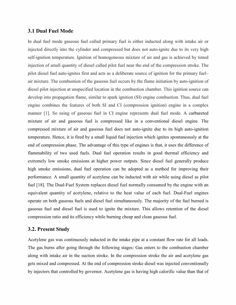
1.2 Significance of Alternative Fuels
All these years there have always been some IC engines fuelled with non gasoline or diesel oil
fuels. However, there numbers have been relatively small .Because of the high cost of petroleum
products; some developing countries are trying to use alternate fuels for their vehicles. Another
reason motivating the development of alternate fuels for the IC engine is concern over the
emission problem of gasoline engines. Combined with other air-polluting systems, the large
number of automobiles is a major contributor to the air quality problem of the world. Quite a lot
of improvements have been made in reducing emissions given off by an automobile engine. If a
35% improvement made over a period of years, it is to be noted that during the same time the
lifting the improvement. Lot of efforts has gone into for achieving the net improvement in
cleaning up automobile exhaust. However, more improvements are needed to bring down the
ever-increasing air pollution due to automobile population [27]
One more reason for alternate fuel development is the fact that large percentage of crude oil must
be imported from other countries which control the larger oil fields. As of now many alternate
fuels have been used in limited quantities in automobiles. Quite often, fleet vehicles have been
used for testing (e.g. Taxies, delivery vans and utility company trucks). This allows for
comparison with similar gasoline- fuelled vehicles, and simplifies fuelling of these vehicles.

1.3 Possible Alternative Fuels So many fuels are readily available to replace the fossil fuels in IC Engines. Fuels can be
classified in to 3 forms, viz. Solid, liquid and gaseous fuels.
1.3.1 Solid Fuels- These fuels are nowadays uses in trains and some external combustion
engines like boilers. Some examples for solid fuels are coal and coke.
1.3.2 Liquid Fuels- Vegetable oils have been found to be a potential alternative to diesel. They
have properties comparable to diesel and can be used to run a compression ignition engine with
minor modifications. Alcohols (methanol, ethanol) are also used as fuels in IC engines due to
their high volatility [29].
Gaseous fuels and its significance in engines and in future are clearly discussed in the next steps
1.3.3 Gaseous Fuels
Gaseous fuels are the best suited for IC engines since physical delay is almost nil. However, as
fuel displaces equal amount of air the engines may have poor volumetric efficiency. There are
quite few gaseous fuels that can be used as alternative fuels. Gaseous fuels are the most
convenient requiring the least amount of handling and simplest and most maintenance free
burner systems. Gas is delivered "on tap" via a distribution network and so is suited to a high
population or industrial density. However large consumers do have gas holders and some
produce their own gas.
The following are the types of gaseous fuels:
(A) Fuels naturally found in nature:
Natural gas, Methane from coal mines
(B) Fuel gases made from solid fuel
Gases derived from Coal, Gases derived from waste and Biomass, from other industrial
processes (Blast furnace gas)
(C) Gases made from petroleum
Liquefied Petroleum gas (LPG), Refinery gases, Gases from oil gasification
(D) Gases from some fermentation process

1.4 The Merits of Gaseous Fuels
Some of the merits of gaseous fuels are as follows
i. Gaseous fuels burn very clean
ii. Generally very clean burning. Little soot.
iii. Easy to burn - No grinding or atomization. Excellent mixing
iv. No problems with erosion or corrosion
v. No ash problems
vi. The gas is easy to clean. E.g. if sulphur is present, it may be easily removed prior to
combustion.
vii. Simplest combustion plant of all - Burners
viii. Can be started up and shut down very easily and quickly.
1.5 The Demerits of Gaseous Fuel
Some of the demerits of gaseous fuels are as follows i. Problems with distribution and storage
ii. Explosion risk and very volatile.
iii. Relatively costly. Offset by cheaper and more efficient plant. 1.6 Acetylene Gas
Acetylene (C2H2) is not an air gas, but a synthesis gas generally produced from the
reaction of calcium carbide with water. It was burnt in "acetylene lamps" to light homes and
mining tunnels in the 19th century. A gaseous hydrocarbon, it is colorless, has a strong garlic
odor, is unstable, highly combustible, and produces a very hot flame (over 3000°C or 5400°F)
when combined with oxygen. Acetylene is conventionally produced by reacting calcium carbide
with water. The reaction is spontaneously occurring and can be conducted without any
sophisticated equipment or apparatus. Such produced acetylene has been utilized for lighting in
mine areas, by street vendors, etc. People often call such lighting sources “carbide light” or
“carbide lamps”. Industrial uses of acetylene as a fuel for motors or lighting sources, however,
have been nearly nonexistent. In modern times, the use of acetylene as a fuel has been largely
limited to acetylene torches for welding or welding-related applications. In most such
application, acetylene is generally handled in solution form such as acetylene dissolved in
acetone for example.

1.6.1 Reaction for Production Calcium carbonate reacts with graphite in nature and forms as calcium carbide rocks. These
reactions (i & ii) are taking place naturally. For production of acetylene, calcium carbide should
mix with normal water. So anyone can produce acetylene gas if one can have a gas collecting
container and storage device. In welding shops acetylene is producing in acetylene gas
generators by following this equation only [8].
CaCO3+C (graphite) CaC2 (i)
CaC2+H2O Ca (OH) 2+C2H2 (ii)
1.6.2 Reactions in Combustion
The clean burning nature of acetylene is self evident from the stoichiometric equation (iii)
C2H2+ 2.5 O2 2CO2 + H2O (iii)
Acetylene can explode without the presence of oxygen or air, since it is an unstable substance
which can decompose. In the presence of oxygen, the combustion of acetylene has an even
greater energy release (heat of combustion at 1atm, 20oC) [8]
C2H2 2C+H2+ 8.7kJ/g (iv)
C2H2+ 2.5 O2 2CO2 (g) + H2O (l) + 50kJ/g (v)
The reaction proceeds spontaneously at any temperature and pressure conditions and easily goes
to completion without leaving any residues other than the desired combustion products, namely
carbon dioxide and water. Further, the reaction ideally takes place in a gaseous phase without
any need for catalytic assistance. The gas-phase reaction has several advantages over
heterogeneous reactions such as gas-liquid, gas-solid, and solid-liquid reaction. For example the
gas phase reaction does not require much effort for mixing necessary ingredients, assuring proper
ratios, or handling by products of combustion. Such advantages become very significant in fuel
applications for combustion engines where liquid fuels such as gasoline have been
conventionally used, and gasoline (liquid-phase) and air (gas-phase) intercontact in an engine for
combustion reaction purpose.

1.6.3 Physical and Combustion Properties of Gaseous Fuels and Diesel
Some properties are essential to check before using the fuels in internal combustion engines.
Table 1.1 gives the comparison of physical and combustion properties of acetylene, hydrogen
and CNG gas and the properties of diesel, the pilot fuel were showed in table 1.2.
Table 1.1.Comparison of Physical and Combustion Properties of C2H2, H2 and CNG [20, 24]
Properties Acetylene Hydrogen CNG
Composition C2H2 H2 CH4:86.4-90%; C2H6:3-6%; C3H8:0.35-2%
Density, kg/m3(At 1 atm & 20
o C) 1.092 0.08 0.72
Auto ignition temp( K) 598 845 723
Stoichiometeric air fuel ratio, (kg/kg) 13.2 34.3 17.3
Flammability Limits (Volume %) 2.5-8.1 4-74.5 5.3-15
Flammability Limits (equivalence ratio) 0.3-9.6 0.1-6.9 0.4-1.6
Lower Calorific Value (kJ/kg) 48,225 120,000 45,800
Ignition energy (MJ) 0.019 0.02 0.28
Adiabatic flame temperature(K) 2500 2400 2214
Flame speed(m/s) 1.5 3.5 0.38
Table 1.2 Physical and Combustion Properties of Diesel Properties Diesel
Formula C12 H26
Density, kg/m3(At 1 atm & 20
o C) 840
Auto ignition temp( K) 527
Stoichiometeric air fuel ratio, (kg/kg) 14.5
Flammability Limits (Volume %) 0.6-5.5
Lower Calorific Value (kJ/kg) 42,500
Adiabatic flame temperature(K) 2200
Flame speed(m/s) 0.3

Acetylene gas is having low density, high auto ignition temperature and very little ignition
energy which are close to that of hydrogen. The calorific value of acetylene gas is more than that
of diesel fuel and sufficient flammability limits. So acetylene gas can be used as an alternative
fuel for diesel engine.
1.7 Motivation for the Project
Gaseous fuels are good for clean burning and are abaundantly available in nature but little costly.
Many researchers have worked with hydrogen gas as an alternative fuel. when comapred to
hydrogen,acetylene gas also having almost similar combustion properties like flame speed,
ignition energy, adiabatic flame temperature and flammability limits etc. Auto ignition
temperature also less than that of hydrogen and production, storage cost of acetylene is also less
than that of hydrogen. So many favourable qualities made us to do project with acetylene as
alternative fuel for diesel engine.
Some researchers studied acetylene in diesel engine with different induction techniques like
manifold induction,manifold injection, port injection etc. The present work deals with induction
of acetylene gas, with a flow rate of 2lpm which is lowest calibration in used flow meter, at
different locations viz., 24cm, 40cm, 56cm and 70cm of intake pipe away from the engine intake
manifold and determined the optimum location at which acetylene gas can be inducted. Further,
optimum induction location was taken as constant and inducted acetylene gas at different flow
rates viz., 2lpm, 3lpm, 4lpm and 5lpm to find out optimum flow rates of acetylene gas by
comparing combustion, performance and emisssion characterstics.

CHAPTER 2
LITERATURE SURVEY

G.Nagarajan and T.Lakshamanan [1] conducted experiments on a diesel engine aspirated
acetylene along with air at different flow rates without dual fuel mode. They carried out the
experiment on a single cylinder, air cooled, direct injection (DI), compression ignition engine
designed to develop the rated power output of 4.4 kW at 1500 rpm under variable load condition.
Acetylene aspiration results came with a lower thermal efficiency reduced Smoke, HC and CO
emissions, when compared with baseline diesel operation. With acetylene induction, due to the
high combustion rates, the NO emission significantly increased. Peak pressure and maximum
rate of pressure rise also increased in the dual fuel mode of operation due to the higher flame
speed. It was concluded that induction of acetylene could significantly reduce smoke, CO and
HC emissions with a small penalty on efficiency.
Swami Nathan et al. [2] conducted experiments on sole acetylene fuel in HCCI mode and shown
the results with high thermal efficiencies in a wide range of BMEP. The thermal efficiencies
were comparable to the base diesel engine and a slight increase in brake thermal efficiency was
observed with optimized EGR operation. The intake charge temperature and amount of EGR
have to be controlled based on the output of engine and at high BMEPs hot EGR leads to knock.
The values of NOx, smoke are reduced by HCCI combustion, but HC emissions are more
compared with base line diesel fuel.
T.Lakshamanan et al [3] conducted experiments to study the performance and emission
characteristics of DI diesel engine in dual fuel mode of operation by aspirating acetylene gas at
constant 3lpm in the inlet manifold for various loads, with diesel as an ignition source. The brake
thermal efficiency in dual fuel mode was found as lower than diesel operation at full load, as a
result of continuous induction of acetylene in the intake. They state that acetylene would
compete with hydrogen in the near future for use of alternative fuel in internal combustion
engines. It was suggested that by applying certain techniques like, TMI, TPI the thermal
efficiency can be improved with a reduced NOx emissions level.
Wulff et al [4] studied the behavior of diesel at different power conditions and speeds by
sending acetylene as primary fuel and diesel as secondary fuel as dual fuel mode at different
power outputs and different speeds and achieved positive results like reduction in NOx, HC and
CO emissions compared to base line diesel fuel.

T.Lakshamanan et al [6] studied the performance and emissions characteristics of acetylene
fueled engine at different flow rates by using timed manifold injection technique. The study
revealed that the optimum condition in manifold injection technique was 10o ATDC with
injection duration of 90o crank angle and resulted a marginal increase in brake thermal efficiency
was noticed for all gas flow rates. NOx emission decreased according to the flow rates and slight
increased in smoke levels. The reduction in HC, CO, CO2 emissions were also observed.
T. Lakshmanan et.al [7] conducted experiments with acetylene which was injected in the intake
manifold in a single cylinder diesel engine, with a gas flow rate of 240 g/h, start of injection time
is 10oaTDC and 90o CA (9.9 ms) duration, operated in dual fuel mode. In order to decrease the
NOx emissions from acetylene diesel engine, cooled EGR was employed. The cylinder pressure,
brake thermal efficiency and emissions such as NOx, smoke, CO, HC, CO2 and exhaust gas
temperature were studied. Dual fuel operation with acetylene induction coupled with cooled
EGR results in lowered NOx emissions and improved part load performance
John W.H. Price [8] described the explosion of an acetylene gas cylinder, which occurred in
1993 in Sydney. The failure caused severe fragmentation of the cylinder and resulted in a fatality
and property damage. The paper also described the failure and the circumstances surrounding it.
He examined the nature of the explosion which occurred and sought an explanation of the events.
He gave more information to prevent accidents regarding while using acetylene and the reactions
take place in combustion and safety precautions.
T.Lakshmanan [9] conducted experiments with the gas flow rate was fixed at 110 g/h, 180 g/h
and 240 g/h. The combustion, performance and emission parameters were studied for the above
flow rates by varying the load from low load to full load. Results show that NOx, HC and CO
emissions reduced when compared to diesel operation due to leaner operation. A marginal
increase in smoke emission was observed and brake thermal efficiency was nearer to diesel
operation. On the whole it is concluded that without loss in thermal efficiency, safe operation of
acetylene is possible in timed port injection technique. Reduced NOx, HC and CO emission
levels, with marginal increase in smoke emission level were achieved.

G.A.Rao et al [10] studies are with LPG in diesel engine in dual fuel mode.LPG carburetor is
incorporated on the intake side of the engine. The LPG energy substitution could be done up to
50% at lower loads and up to 20% at higher loads. The engine performance is better on pure
diesel up to engine loads of about 35%.at higher loads; the dual fuel mode is superior to the pure
diesel mode of operation, compared to that of pure diesel operation.
B.B.Sahoo et al [12] reviewed on the effect of engine parameters while using gaseous fuels in
dual fuel mode. He considered that the engine operating and design parameters, namely, load,
speed, pilot fuel injection timing, pilot fuel mass, compression ratio, inlet manifold conditions,
and type of gaseous fuel, that play an important role in the performance of dual-fuel diesel
engines. There was a minor reduction in power output and higher BSFC for the engines. Lower
peak cylinder pressure was noticed for a dual-fuel engine compared to the normal diesel engine
at a given load condition, which is encouraging since no danger exists for the engine structure.
The rate of Pressure rise increases with increase in load and is always higher than that of diesel
fuel case. Combustion duration is longer compared to diesel operation at low load. Lower NOx
and drastic decrease in soot emissions with all gaseous fuels. But, at all load conditions, CO and
HC emissions are considerably high compared to the diesel case. With respect to engine speed,
the thermal efficiency improves with increasing engine speed. Maximum combustion pressure is
slightly higher than the diesel fuelling level at constant engine speed. The rate of pressure rise
decreases with increase in engine speed and is higher than that of diesel operation. While
considering the pilot fuel injection timing, higher thermal efficiency is achieved by advancing
the injection timing. The maximum cylinder pressure and rate of pressure rise are higher for the
advanced injection timing compared with diesel operation. Advancing the injection timing at
medium and high loads led to early knocking. Higher NOx emission, and a lower CO and UBHC
emissions are noticed with advance injection timing. There is an improvement in thermal
efficiency and torque output by increasing the amount of pilot fuel. Early knocking is noticed
with increase in the amount of pilot fuel at high loads. Increasing the pilot fuel and reducing
primary fuel reduces the knocking phenomena. By increasing the amount of pilot fuel, higher
NOx and reductions in CO and UBHC were noticed. EGR technique improves the brake thermal
efficiency and more than 50% causes the deterioration of combustion characteristics. Increasing
the mass of gaseous fuel, the combustion noise and maximum pressure increases for methane,
CNG and LPG.

Mohamed Y.E. Selim [13] investigated the effects of differences in gas composition on engine
performance, knocking and ignition limits and combustion noise characteristics of a dual fuel
engine. The dual fuel engine uses Diesel fuel as pilot fuel, while the main fuel is the gaseous fuel
injected in the intake manifold. In the present study, they used three gaseous fuel namely pure
methane (CH4), compressed natural gas (CNG) and liquefied petroleum gas (LPG). The effects
of some engine operating and design parameters e.g. load, speed, compression ratio, pilot fuel
injection timing and pilot fuel mass on the combustion characteristics for the three gases,
performance, knocking and ignition limits and combustion noise of the dual fuel engine shall be
studied.
Mohamed Y.E. Selim [14] conducted experiments on single cylinder, naturally aspirated, four
stroke, Ricardo E6 engine converted to run as dual fuel engine on diesel and gaseous fuel of LPG
or methane. The data for each cycle of operation were analyzed for the maximum pressure, the
maximum rate of pressure rise that representing the combustion noise, and indicated mean
effective pressure. The cycle-to-cycle variation is expressed as the mean value, standard
deviation, and coefficient of variation of these three parameters. It was found that the type of
gaseous fuel and engine operating and design parameters affected the combustion noise and its
cyclic variation and these effects have been presented in this paper.
Karim [15] did an extensive research to understand the nature of the combustion process in the
dual fuel mode in CI engine. He used variety of gases like methane, ethane, propane, butane,
hydrogen, ethylene, and acetylene as primary fuel. He proved that the performance of dual fuel
engines, irrespective of the type of gaseous fuel employed, is better at medium and high loads.
However, it has been reported that at low outputs efficiency is slightly inferior to the base line
diesel engine. Researchers have stressed the need to control the quantity of both pilot and
gaseous fuel depending on load conditions for better performance.
Das [17] suggested that hydrogen could be used in both SI engine and CI engine without any
major modification in the existing system. He studied different modes of hydrogen induction by
carburetion, continuous manifold injection (CMI), timed manifold injection (TMI), low pressure
direct injection (LPDI), and high pressure direct injection (HPDI); and suggested to use manifold

injection method for induction of gases to avoid undesirable combustion phenomenon (back fire)
and rapid rate of pressure rise.
M. Senthil Kumar et al [18] concluded that hydrogen can be inducted along with air to improve
the performance and reduce hydrocarbons and smoke emissions of a Jatropha oil fuelled
compression ignition engine with cleared dual fuel mode concept. The most significant
environmental penalty will be an increase of NO emission. The amount of hydrogen that can be
added depends on the output. At full load 7% of the total mass of fuel admitted has to be
hydrogen for optimal performance. At low outputs it is not advantages to use hydrogen
induction.
Murari Mohon Roy et al [21] Two types of producer gases were used in their study in diesel
engine, one with low hydrogen content (H2 =13.7%) and the other with high hydrogen content
(H2 = 20%). The engine was tested for use as a co- generation engine. Experiments were carried
out at a constant injection pressure and injection quantity for different fuel–air equivalence ratios
and at various injection timings. The experimental study was to optimize the injection timing to
maximize the engine power at different fuel–air equivalence ratios without knocking and within
the limits of the maximum cylinder pressure. Better combustion, engine performance, and
exhaust emissions (except NOx) were obtained with the high H2-content producer gas than with
the low H2-content producer gas, especially under leaner conditions. Moreover, a broader
window of fuel–air equivalence ratio was found with highest thermal efficiencies for the high
H2-content producer gas.
M.A. Escalante Soberanis et al. [22] presented the most significant advances and developments
made on the technical adaptations in the internal combustion engines which operate with
mixtures of gas/hydrogen, doing more emphasis in the fuel injection and cooling systems. To
understand such technical adaptations, it is necessary to know the chemical and physical
characteristics of hydrogen, and the processes relate with the chemical reaction between air and
hydrogen, from a point of view of the thermo-chemistry and the chemical kinetics, as well as the
ratios of the mixtures in the combustion process. Also, it mentioned the advantages and
disadvantages of the integration of hydrogen as a fuel, such as the pre-ignition, spontaneous
ignition, knocking and backfire, also the advances in the research to avoid these phenomena

during the combustion. Finally, it suggested the best conditions of the ratio-mixtures in the
internal combustion engines when they are fed with hydrogen.
L.M Das [23] shows the techniques with which hydrogen gas can induct into the diesel engine
and effect of engine parameters with induction technique has been discussed in this paper.
From all the literature that was noticed acetylene was inducted in different ways i.e., manifold
induction, port induction, direct injection in dual fuel mode. Some researchers induct hydrogen
and varied according to load and compared with diesel and some other vegetable oils. But there
was a lack of literature about where they inducted gaseous fuel along with air away from the
engine manifold. The present work is to contribute some past data and experience for the future
investigations.

CHAPTER 3
EXPERIMENTATION
3.1 Dual Fuel Mode
In dual fuel mode gaseous fuel called primary fuel is either inducted along with intake air or
injected directly into the cylinder and compressed but does not auto-ignite due to its very high
self-ignition temperature. Ignition of homogeneous mixture of air and gas is achieved by timed
injection of small quantity of diesel called pilot fuel near the end of the compression stroke. The
pilot diesel fuel auto-ignites first and acts as a deliberate source of ignition for the primary fuel–
air mixture. The combustion of the gaseous fuel occurs by the flame initiation by auto-ignition of
diesel pilot injection at unspecified location in the combustion chamber. This ignition source can
develop into propagation flame, similar to spark ignition (SI) engine combustion. Thus, dual fuel
engine combines the features of both SI and CI (compression ignition) engine in a complex
manner [1]. So using of gaseous fuel in CI engine represents dual fuel mode. A carbureted
mixture of air and gaseous fuel is compressed like in a conventional diesel engine. The
compressed mixture of air and gaseous fuel does not auto-ignite due to its high auto-ignition
temperature. Hence, it is fired by a small liquid fuel injection which ignites spontaneously at the
end of compression phase. The advantage of this type of engines is that, it uses the difference of
flammability of two used fuels. Dual fuel operation results in good thermal efficiency and
extremely low smoke emissions at higher power outputs. Since diesel fuel generally produce
high smoke emissions, dual fuel operation can be adopted as a method for improving their
performance. A small quantity of acetylene can be inducted with air while using diesel as pilot
fuel [18]. The Dual-Fuel System replaces diesel fuel normally consumed by the engine with an
equivalent quantity of acetylene, relative to the heat value of each fuel. Dual-Fuel engines
operate on both gaseous fuels and diesel fuel simultaneously. The majority of the fuel burned is
gaseous fuel and diesel fuel is used to ignite the mixture. This allows retention of the diesel
compression ratio and its efficiency while burning cheap and clean gaseous fuel.
3.2. Present Study
Acetylene gas was continuously inducted in the intake pipe at a constant flow rate for all loads.
The gas burns after going through the following stages: Gas enters to the combustion chamber
along with intake air in the suction stroke. In the compression stroke the air and acetylene gas
gets mixed and compressed. At the end of compression stroke diesel was injected conventionally
by injectors that controlled by governor. Acetylene gas is having high calorific value than that of

diesel and it compensates some of the energy by diesel. So there was a reduction in diesel
consumption and diesel acts as pilot fuel to initiates the combustion reaction at the end of the
compression stroke of diesel engine.
pilot fuel and continues with primary fuel. Here acetylene as a primary fuel for the engine and
diesel as a pilot fuel. In the present study
acetylene as an alternative fuel in a compression ignition engine.
at different locations viz., 24cm, 40cm, 56cm and 70cm away from the intake manifold of the
engine shown in below fig 3.1 and diesel injected conventionally in the cylinder
taken as constant flow rate because
measurement of 2lpm.
Fig 3.1.Acetylene
The combustion, performance and emission characteristics of the diesel engine were evaluated,
compared with diesel fuel operation. Based
location of induction was optimized
rates of acetylene viz., 2lpm, 3lpm, 4lpm
main fuel. The combustion, performance and emission characteristics of the diesel engine were
evaluated, compared with diesel fuel oper
parameters, the flow rate of acetylene
e of the energy by diesel. So there was a reduction in diesel
consumption and diesel acts as pilot fuel to initiates the combustion reaction at the end of the
compression stroke of diesel engine. In dual fuel mode the combustion reaction is start with
and continues with primary fuel. Here acetylene as a primary fuel for the engine and
In the present study an experimental investigation was
as an alternative fuel in a compression ignition engine. Initially acetylene was inducted
s viz., 24cm, 40cm, 56cm and 70cm away from the intake manifold of the
shown in below fig 3.1 and diesel injected conventionally in the cylinder
taken as constant flow rate because the flow meter used in the study had least value of
Fig 3.1.Acetylene Gas Induction at Different Locations
The combustion, performance and emission characteristics of the diesel engine were evaluated,
compared with diesel fuel operation. Based on the performance and emission parameters,
location of induction was optimized. Further, with the optimum induction location, different flow
rates of acetylene viz., 2lpm, 3lpm, 4lpm and 5lpm were inducted while diesel was injected as
main fuel. The combustion, performance and emission characteristics of the diesel engine were
evaluated, compared with diesel fuel operation. Based on the performance and emission
flow rate of acetylene was optimized.
e of the energy by diesel. So there was a reduction in diesel
consumption and diesel acts as pilot fuel to initiates the combustion reaction at the end of the
In dual fuel mode the combustion reaction is start with
and continues with primary fuel. Here acetylene as a primary fuel for the engine and
carried out with
Initially acetylene was inducted
s viz., 24cm, 40cm, 56cm and 70cm away from the intake manifold of the
shown in below fig 3.1 and diesel injected conventionally in the cylinder. This 2lpm was
the flow meter used in the study had least value of
The combustion, performance and emission characteristics of the diesel engine were evaluated,
on the performance and emission parameters, the
location, different flow
5lpm were inducted while diesel was injected as
main fuel. The combustion, performance and emission characteristics of the diesel engine were
on the performance and emission

3.3. Accessories using for Conducting Experiment
By considering the drawbacks of gaseous fuel some preventive methods should be adopted while
using them. There was a need of using accessories to avoid accidents when experiment is
carrying on. Accessories used in the experiment are shown below with figures.
a. Acetylene cylinder
b. Pressure regulator
c. Flow meter
d. Flash back arrestor
e. Hose pipe
3.3.1 Acetylene Cylinder
The 3 feet brown colored acetylene cylinder contains 5.5 kg of acetylene i.e. 5 cubic meter of
acetylene gas in compressed state. The density of acetylene gas is 1.092 kg/m3. Full cylinder
contains gas at a pressure of 15bar and the gas can allow outside by using pressure regulator. The
acetylene cylinder connected with pressure regulator, flow meter, flash back arrestor and hose
pipe is shown in fig 3.2.
Fig 3.2 Acetylene cylinder
3.3.2 Pressure Regulator
The pressure regulator used to regulate the pressure in the flow passage. It connects between
high pressure cylinder and low pressure hose pipe that connect to the inlet manifold of engine.

Fig 3.3 Pressure Regulator
The used pressure regulator shown in fig 3.3 which is two stage pressure reducer and the limits
are as follows:
High pressure side (cylinder side): 0- 40 bar
Low pressure side (engine side): 0- 2.5 bar
3.3.3 Flow Meter
A gas flow meter is used to measure the flow rate of gases with which gas is flowing through
that. Gases are more difficult to measure than liquids, as measured volumes are highly affected
by temperature and pressure. Gas meters measure a defined volume, regardless of the pressurized
quantity or quality of the gas flowing through the meter. Temperature, pressure and heating value
compensation must be made to measure actual amount and value of gas moving through a meter.
The flow meter is connected between pressure regulator and flash back arrestor is shown in fig
3.4.
Fig 3.4 Flow meter

The calibration limits of flow meter are 2lpm to 40lpm and least count of used flow meter is
1lpm.
3.3.4 Flame Arrester or Flash Back Arrestor
A flashback arrestor or flame arrestor is a device used here to stop the flame from burning
back up into the equipment and causing damage or explosions. The two main types are dry
and wet. Each has its own advantages and disadvantages. Most oxy-fuel flashback arrestors
are the dry type.
a) Dry type: Dry flashback arrestors typically use a combination of methods to stop
flashback. This is the type that is typically found on most workshops, home or portable
oxy-fuel kits as they work just as effectively with any orientation, need very little
maintenance, and are often small and light enough to be installed between the torch and
hoses.
b) Wet type: Liquid seal flame arrestors are liquid barriers following the principle of a
siphon where the liquid stops the entering deflagration and/or detonation and
extinguishes the flame; they work by bubbling the gas through a non-flammable and
ideally non-gas-absorbing liquid, which is typically water. They stop the flame by
preventing it from reaching the submerged intake. These devices are normally very
effective at stopping flashbacks from reaching the protected side of the system.
The flash back arrestor was connected between flow meter and hose pipe is shown in fig 3.5
Fig 3.5.Flash Back Arrestor

3.4 Engine Setup
A single cylinder, four stroke, air-cooled and naturally aspirated DI diesel engine designed to
develop a power of 4.4kw at 1500 rpm was used for the experimental study. Acetylene was
introduced into intake manifold along with air by a non return valve arrangement through a
flashback arrestor. The flow of acetylene was controlled by pressure regulator and was measured
by a calibrated gas flow meter. The air flow was measured by a pressure drop across a sharp
edge orifice of the air surge chamber and by sensors. Fuel consumption was determined by using
a calibrated burette with an accuracy of 0.1 CC. The pressure time history of cylinder was
measured by a pressure transducer, which was mounted on the cylinder head. The crankshaft
position was obtained using a crankshaft angle sensor to determine cylinder pressure as a
function of the CA. The CA signal was obtained from an angle-generating device mounted on
the main shaft. A laptop is provided with data acquisition system to collect the data from all
sensors and stored for offline calculations. The exhaust gas constituents CO, CO2, HC, NO, O2
were measured by AVL gas analyzer and smoke density can be measure by AVL smoke meter.
A schematic diagram of experimental arrangement is shown in Fig 3.6 and technical
specifications of the engine are given in Table 3.1.
Table 3.1 Engine Technical Specifications
Make/Model Kirloskar TAF 1 Brake power, kW 4.4 Rated speed, rpm 1500 Bore [mm] 87.5 Stroke [mm] 110 Compression Ratio 17.5:1 Nozzle Opening pressure [bar] 200 Injection Timing [BTDC ,oCA] 23

3.5 Uncertainty Analysis Every experiments is not very accurate and having some errors.
experiments can arise from instrument selection, condition, calibration, environment,
observation, reading and test planning. Uncertainties analysis is needed to
the experiments. An uncertainty analysis was performed using the method described by
The list of instruments used for measuring various parameters and measurement techniques are
presented in Table 3.2. The total percentage of
given below:
Total percentage uncertainty of this experiment is
= Square root of { (uncertainty of TFC)
(uncertainty of brake thermal efficiency)
(uncertainty of UBHC)2 + (uncertainty of NO)
smoke number)2 + (uncertainty of EGT)
flow meter)2+(uncertainty in pressure regulator)
Fig 3.6 .Experimental setup
Every experiments is not very accurate and having some errors. Errors and uncertainties in the
experiments can arise from instrument selection, condition, calibration, environment,
observation, reading and test planning. Uncertainties analysis is needed to prove the accuracy of
the experiments. An uncertainty analysis was performed using the method described by
The list of instruments used for measuring various parameters and measurement techniques are
The total percentage of uncertainty of this experiment is calculated as
Total percentage uncertainty of this experiment is
(uncertainty of TFC)2 + (uncertainty of BP)2 + (uncertainty of BSFC)
(uncertainty of brake thermal efficiency)2 + (uncertainty of CO)2 + (uncertainty of CO
+ (uncertainty of NO)2 + (uncertainty of O2)2 + (uncertainty of AVL
+ (uncertainty of EGT)2 + (uncertainty of pressure pick up)2
ty in pressure regulator)2 }
Errors and uncertainties in the
experiments can arise from instrument selection, condition, calibration, environment,
prove the accuracy of
the experiments. An uncertainty analysis was performed using the method described by Holman.
The list of instruments used for measuring various parameters and measurement techniques are
uncertainty of this experiment is calculated as
+ (uncertainty of BSFC)2 +
+ (uncertainty of CO2)2 +
+ (uncertainty of AVL 2+(uncertainty in

=√{(1.5 )2 +(0.2) 2 +(1.5) 2+(1.0) 2+(0.03) 2+(0.15) 2+(0.2) 2+(0.2) 2+ (1.0)2 + (1.0) 2+(0.15) 2 +
(1.0) 2+(0.5)2+(0.5)2} = ± 3.027
Using the calculation procedure, the total uncertainty for the whole experimentation is obtained
to be ± 3.027
Table 3.2 List of Instruments used for measuring Various Parameters and Measurement Techniques
Instrument Purpose Make and model Measurement techniques Exhaust gas analyzer Measurement of HC, CO,
CO2, O2, NO emissions AVL 444 CO, CO2 - NDIR principle
(non depressive infra infra-red sensor), HC – FID (Flame Ionization detector), NOx-CLD (Chemiluminescence detector), O2 - electrochemical sensor
Smoke meter Measurement of smoke emissions
AVL 437C Hatridge smokemeter
Pressure transducer and charge amplifier
Measurement of cylinder pressure
Type 5395A, Kistler Instruments, Winterthur,
Switzerland
Type 1100A3, Cr-Ni-St.seal
Crank angle encoder Legion Brothers Magnetic pick up type Load indicator Loading device

CHAPTER 4
RESULTS AND DISCUSSIONS -I
OPTIMIZATION OF INDUCTION LENGTHS
4.1Combustion Parameters
4.1.1 Pressure Crank Angle Diagram
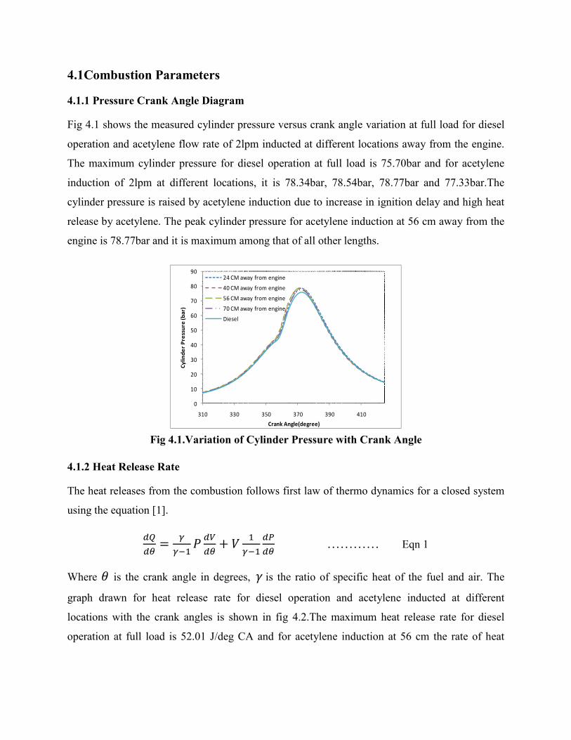
Fig 4.1 shows the measured cylinder pressure versus crank angle variation at full load for diesel
operation and acetylene flow rate of 2lpm inducted at different locations away from the engine.
The maximum cylinder pressure for diesel operation at full load is 75.70bar and for acetylene
induction of 2lpm at different locations, it is 78.34bar, 78.54bar, 78.77bar and 77.33bar.The
cylinder pressure is raised by acetylene induction due to increase in ignition delay and high heat
release by acetylene. The peak cylinder pressure for acetylene induction at 56 cm away from the
engine is 78.77bar and it is maximum among that of all other lengths.
0
10
20
30
40
50
60
70
80
90
310 330 350 370 390 410
Cylin
der
Pres
sure
(bar
)
Crank Angle(degree)
24 CM away from engine
40 CM away from engine
56 CM away from engine
70 CM away from engine
Diesel
Fig 4.1.Variation of Cylinder Pressure with Crank Angle
4.1.2 Heat Release Rate
The heat releases from the combustion follows first law of thermo dynamics for a closed system
using the equation [1].
��
���
�
�����
�� �
�
���
��
�� ………… Eqn 1
Where is the crank angle in degrees,����is the ratio of specific heat of the fuel and air. The
graph drawn for heat release rate for diesel operation and acetylene inducted at different
locations with the crank angles is shown in fig 4.2.The maximum heat release rate for diesel
operation at full load is 52.01 J/deg CA and for acetylene induction at 56 cm the rate of heat

release is marginally increased to 52.08 J/deg CA. For the remaining acetylene induction lengths
it is less due to improper mixing and getting less energy share of acetylene fuel [3].
-10
0
10
20
30
40
50
60
270 290 310 330 350 370 390 410
Hea
t Rel
ease
Rat
e(J/
deg
CA)
Crank Angle(degree)
24 CM away from engine40 cm away from engine56 cm away from engine70 cm away from engineDiesel
Fig 4.2.Variation of Heat Release Rate with Crank Angle
4.1.3 Peak Cylinder Pressure
The graph drawn between Peak cylinder pressure and load for diesel and acetylene flow rate of
2lpm inducted at different locations is shown in fig 4.3. The range of peak cylinder pressure for
diesel operation is from 54.91bar to 75.70bar for no load to full load. And for acetylene
induction of 2lpm it is in the range is of 55.61bar to78.77bar i.e. peak pressure is increased by
about 4% to diesel operation at full load due to increase in ignition delay [18]. The peak cylinder
pressures for acetylene induction (2lpm) are more than that of diesel operation at full load and
they are 78.34bar, 78.54bar, 78.77bar and 77.33bar for 24cm, 40cm, 56cm and 70cm
respectively.
50
55
60
65
70
75
80
85
0 1000 2000 3000 4000
Peak
Cyl
inde
r Pr
essu
re(b
ar)
Load(watt)
24 CM away from engine
40 CM away from engine
56 CM away from engine
70 CM away from engine
Diesel
Fig 4.3.Variation of Peak Cylinder Pressure with Load

4.1.4 Ignition Delay
The variation of ignition delay with load is shown in fig 4.4 for diesel and acetylene inducted at
different locations. Ignition delay is the time taken (deg CA) between start of injection of fuel
and start of ignition. The ignition delay for diesel in the range of 15.05oCA to 11.293oCA from
no load to full load. While acetylene induction at 2lpm in diesel engine, the ignition delay
becomes higher than that of diesel for the entire load spectrum due to improper mixing of diesel
and air in presence of acetylene gas [3]. The values of ID for acetylene induction at full load are
12.1oCA, 12.1oCA, 12.1oCA, and 12.4oCA for 24 cm, 40 cm, 56 cm and 70 cm respectively.
10
11
12
13
14
15
16
17
0 1000 2000 3000 4000
Ign
itio
n D
ela
y(d
eg
CA
)
Load(watt)
24 CM away from engine40 CM away from engine56 CM away from engine70 CM away from engineDiesel
Fig 4.4.Variation of Ignition Delay with load
4.2 Performance Parameters
The term performance usually means how well an engine is doing its work in relation to the
input energy or how effectively it provides useful energy in relation to some other comparable
engines [27]. Some performance parameters were compared between diesel and acetylene
induction at a flow rate of 2lpm inducted at different locations away from intake manifold was
discussed below.
4.2.1 Brake Thermal Efficiency
The graph shown in fig 4.5 is drawn between load and brake thermal efficiency of diesel engine
when acetylene is inducted at different locations. The brake thermal efficiency is decreasing
while acetylene is inducted as supplementary fuel. The brake thermal efficiency is marginally

decreasing with acetylene induction of 2lpm irrespective of length due to high combustion rate
and fast energy release [3].
0
5
10
15
20
25
30
35
0 1000 2000 3000 4000
Brak
e Th
erm
al E
ffic
ienc
y(%
)
Load(watt)
24 CM away from engine
40 CM away from engine
56 CM away from engine
70 CM away from engine
Diesel
Fig 4.5.Variation Brake Thermal Efficiency with Load
As the induction distance increases away from engine 24 cm, 40 cm, 56 cm and 70 cm the brake
thermal efficiency is increasing but up to 56 cm and it is decreasing later like 28.54%, 29.30%,
29.62% and 29.06%. The reason may be due to the time for mixing of gas and air is increasing
and diesel may unable to mix properly with air alone. So diesel role in giving heat input is
reducing.
4.2.2 Exhaust Gas Temperature
The graph shown in fig 4.6 is drawn between load and exhaust gas temperature. The exhaust gas
temperature is increasing with acetylene induction when compared to diesel operation may be
due to more energy input with acetylene gas. The EGT is in the range of 120oC to 366oC for
diesel operation and it is 144oC to 385oC for acetylene induction for 2lpm. The exhaust gas
temperature reached to 385oC while gas inducting at 56 cm away from the engine and it is more
compared to other distances at full load. The increase in exhaust gas temperature while inducting
acetylene gas at 56 cm is may be due to high heat release by diesel due to consumption of diesel
is more at that location. So EGT graph is useful for optimizing the location at which acetylene
gas can be inducted in the intake pipe along with air.

0
50
100
150
200
250
300
350
400
450
0 500 1000 1500 2000 2500 3000 3500 4000
Exh
aust
gas
Te
mp
era
ture
(°C
)
Load(watt)
24 CM away from engine
40 CM away from engine
56 CM away from engine
70 cm away from engine
Pure Diesel
Fig 4.6.Variation of Exhaust Gas Temperature with Load
4.2.3 Brake Specific Energy Consumption
The variation of brake specific energy consumption with load for all locations is shown in fig
4.7. As the induction of acetylene provides more energy share compared to that of diesel, the
brake specific energy consumption increases. BSFC for diesel is in the range of 21.8 MJ/kw.hr to
11.7 MJ/kw.hr for no load to full load. The distance of acetylene induction is away from the
engine the energy consumption is more compared to that of diesel operation. But while using
acetylene gas at 2lpm the diesel consumption is reduced 6 % to the normal diesel operation.
10
12
14
16
18
20
22
24
26
0 1000 2000 3000 4000
BS
EC
(Mj/
kw
.hr)
Load(watt)
24 CM away from engine
40 CM away from engine
56 CM away from engine
70 CM away from engine
diesel
Fig 4.7.Variation of Brake Specific Energy Consumption with Load

4.3 Emission Parameters
Internal combustion engines generate undesirable emissions during the combustion process.
Some emissions that exhausted from engine are discussed below and after the results were
compared between diesel and acetylene induction of 2lpm are as follows.
4.3.1 Carbon Monoxide
Carbon monoxide present in the exhaust gas is due to unavailability of oxygen during the
combustion process. Poor mixing, local rich regions and incomplete combustion will also be the
source for CO emissions [27] .The carbon monoxide values for diesel are in range of 0.02% to
0.01% and it is getting more while inducting 2lpm of acetylene gas. Some amount of acetylene
gas replacing air in the intake pipe that leads to insufficient of air for proper combustion and fuel
becomes rich mixture. This may be the reason for getting more CO emissions while using
acetylene gas as fuel. Fig 4.8 shows that the CO emission values are getting high for acetylene
induction of 2lpm irrespective of induction length and for induction length of 56cm the CO
values are reducing with load compared to other induction lengths. But at full loads the values of
CO are getting same as diesel operation. At low loads acetylene induction results in more CO
emissions due to improper mixing and availability of rich mixture at some places in the
combustion cylinder. The CO values are same for all induction lengths (0.01%) and it is same for
diesel operation at full load.
0
0.005
0.01
0.015
0.02
0.025
0.03
0.035
0.04
0.045
0 1000 2000 3000 4000
Ca
rbo
n M
on
oxi
de
(%)
Load (watt)
24 CM away from engine40 CM away from engine56 CM away from engine70 CM away from engineDiesel
Fig 4.8.Variation of Carbon Monoxide with Load

4.3.2 Unburnt Hydrocarbons
Because of non homogeneity of fuel air mixture some local spots in the combustion chamber will
be too lean to combust properly. Other spots may be too rich, without enough oxygen to burn all
the fuel. With under mixing some fuel particles in fuel rich zone never react due to lack of
oxygen. By induction of acetylene at 2lpm, there was a little replacement of intake air by
acetylene which causes low volumetric efficiency and leads to improper mixing of fuel [27]. The
HC emissions for diesel are in the range of 22 to 14ppm and by acetylene induction these values
are raised to range of 28ppm to 16ppm which is 15 % increase in HC emissions. The fig 4.9 is
the graph drawn on unburnt hydrocarbon emissions for different induction length of acetylene
and for diesel. It shows that, if the acetylene induction from 56 cm away from engine gives less
UHC (12ppm) when compared to other induction lengths(13,12.5,16ppm) and more over for
simple diesel(14ppm) operation also.
0
5
10
15
20
25
30
0 1000 2000 3000 4000
Un
bu
rnt
Hy
dro
carb
on
s(p
pm
)
Load(watt)
24 CM away from engine40 CM away from engine56 CM away from engine70 CM away from engineDiesel
Fig 4.9.Variation of Unburnt Hydrocarbons with Load
4.3.3 Nitric Oxide
NOx emissions were resulted by attaining very high temperatures in the combustion chamber. In
cylinder pressure and fuel air ratio also decides the NOx Emission in the exhaust gas [27]. By the
fig 4.10 the values of NO emissions for diesel are in the range of 115ppm to 502ppm from no
load to full load and for acetylene induction of 2lpm the values are 560ppm, 533ppm, 518ppm
and 520ppm at full load for 24 cm, 40 cm, 56 cm and 70 cm away from engine respectively. As
the induction distance increases away from the engine the NO emissions are decreasing up to 56

cm and slightly increasing later. The increasing in NO emissions is due to increase in
temperature and in cylinder pressure when compared to that of diesel operation [3].
0
100
200
300
400
500
600
0 1000 2000 3000 4000
Nit
ric
Oxo
de
(pp
m)
Load(watt)
24 CM away from engine40 CM away from engine56 CM away from engine24 CM away from engineDiesel
Fig 4.10.Variation of Nitric oxide with Load
All the above graphs for performance, combustion and emission parameters shows the
comparison between the simple diesel operation and acetylene induction at different lengths
away from the engine intake manifold. For optimizing the length of induction of acetylene the
performance, combustion and emission parameter were analyzed. The peak pressure is
increasing while using acetylene but at while acetylene induction at 56 cm the peak pressure
decreases slightly compared to other induction lengths. The thermal efficiency is marginally
increasing and diesel consumption was reduced 6 % to diesel operation while acetylene
induction at56 cm with a flow rate of 2lpm. While considering emission parameters the CO,
UHC and NO Emissions are less for acetylene induction at 56 cm is low when compared with
other induction lengths. Most of the parameters are useful to suggest the optimum length of
acetylene induction i.e. at 56 cm away from the engine.

CHAPTER 5
RESULTS AND DISCUSSIONS-II
OPTIMIZATION OF
INDUCTION FLOW RATES

5.1 Combustion Parameters
5.1.1 Pressure Crank Angle Diagram The fig 5.1 shows the variation of cylinder pressure with crank angle. The peak pressure for
diesel operation at full load is 75.7bar at 12 degrees after TDC. Peak pressure for different flow
rates are 78.77 bar at 11 degrees after TDC for 2lpm of acetylene induction, 80 bar at 10 degrees
after TDC for 3lpm of acetylene induction, 86.89 bar at 7.5 degrees after TDC for 4lpm of
acetylene induction, 87.5 bar at 8.5 degrees after TDC for 5lpm of acetylene induction. The
advancement in attaining peak pressure is due to high rate of pressure rise while inducting
acetylene gas compared to that of diesel operation. The advancement in peak pressures while
inducting gas because of instantaneous combustion i.e. in first stage of combustion the acetylene
gets fired and burnt very quickly and for second stage the diesel was burned progressively [1].
0
10
20
30
40
50
60
70
80
90
100
310 330 350 370 390 410
Co
mb
ust
ion
Pre
ssu
re(b
ar)
Crank Angle(deg)
2 LPM
3 LPM
4 LPM
5 LPM
Diesel
Fig 5.1.Variation of Cylinder Pressure with Crank Angle
5.1.2 Heat Release Rate
The graph is drawn between heat release rate and crank angle is shown in fig 5.2 below. The
combustion of acetylene takes place in four stages; first stage is pre-oxidation reaction of the gas,
second stage is combustion of pilot fuel, third stage is premixed combustion phase and the fourth
stage is diffusion combustion phase [9]. The heat release rate for acetylene injection show a brief
premixed combustion phase, followed by slightly higher diffusion combustion phase than diesel
fuel. The highest rate of heat release for diesel is 52 J/deg CA and is marginally decreases to the
acetylene flow rate of 2lpm. The heat release rate for 3lpm, 4lpm, 5lpm are 44.70 J/deg CA,
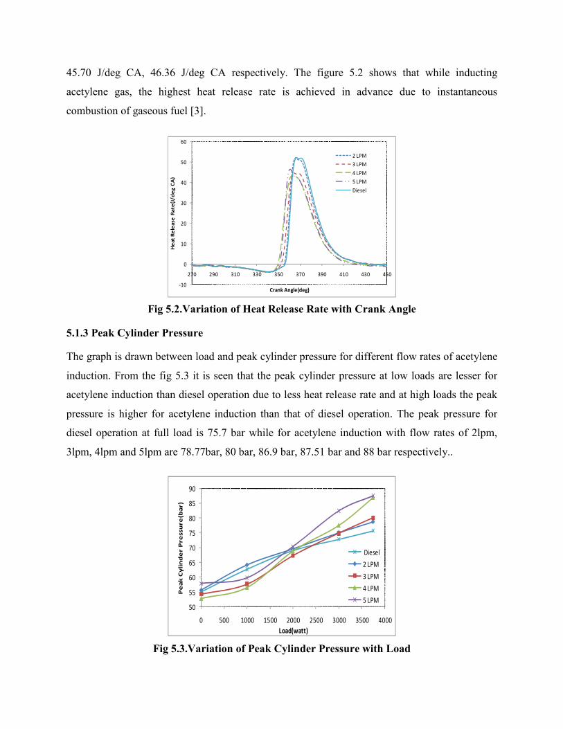
45.70 J/deg CA, 46.36 J/deg CA respectively. The figure 5.2 shows that while inducting
acetylene gas, the highest heat release rate is achieved in advance due to instantaneous
combustion of gaseous fuel [3].
-10
0
10
20
30
40
50
60
270 290 310 330 350 370 390 410 430 450
He
at R
ele
ase
Rat
e(J
/de
g C
A)
Crank Angle(deg)
2 LPM3 LPM4 LPM5 LPMDiesel
Fig 5.2.Variation of Heat Release Rate with Crank Angle
5.1.3 Peak Cylinder Pressure
The graph is drawn between load and peak cylinder pressure for different flow rates of acetylene
induction. From the fig 5.3 it is seen that the peak cylinder pressure at low loads are lesser for
acetylene induction than diesel operation due to less heat release rate and at high loads the peak
pressure is higher for acetylene induction than that of diesel operation. The peak pressure for
diesel operation at full load is 75.7 bar while for acetylene induction with flow rates of 2lpm,
3lpm, 4lpm and 5lpm are 78.77bar, 80 bar, 86.9 bar, 87.51 bar and 88 bar respectively..
50
55
60
65
70
75
80
85
90
0 500 1000 1500 2000 2500 3000 3500 4000
Pe
ak
Cy
lin
de
r P
ress
ure
(ba
r)
Load(watt)
Diesel
2 LPM
3 LPM
4 LPM
5 LPM
Fig 5.3.Variation of Peak Cylinder Pressure with Load

5.1.4 Ignition Delay
The graph is drawn between load and ignition delay for different flow rates of acetylene
induction along with air is shown in fig 5.4. Ignition delay is the time taken in crank angle
between start of injection of diesel fuel and start of ignition [27]. The ignition delay for normal
diesel is in the range of 17oCA to 12.7oCA from no load to full load and for acetylene induction
ignition delay is high at low loads and low at high loads when compared to that of diesel
operation. As the flow rate of acetylene increases, the ID also increasing up to 3lpm and further
increasing flow rate, ID decreases. Ignition delays are12.1oCA for 2lpm, 10.1oCA for both 3 and
4lpm, 7.2oCA for 5lpm. At low loads the ignition delays for acetylene induction is greater than
baseline diesel operation may be due to inability of diesel fuel to mix with air in presence of
acetylene gas. But at full loads may be due to overlapping of valve openings and high diffusion
rate of acetylene results low ignition delays when compared to baseline diesel operation.
0
2
4
6
8
10
12
14
16
18
20
0 1000 2000 3000 4000
Ign
itio
n D
ela
y(d
eg
CA
)
Load(watt)
Diesel2 LPM3 LPM4 LPM5 LPM
Fig 5.4.Variation of Ignition Delay with Load
5.2 Performance Parameters The term performance usually means how well an engine is doing its work in relation to the
input energy or how effectively it provides useful energy in relation to some other comparable
engines [27]. Some performance parameters were compared between diesel and acetylene
induction at a different flow rates inducted at 56 cm away from intake manifold was discussed
below.

5.2.1 Brake Thermal Efficiency
The below graph is drawn between load and brake thermal efficiencies of diesel engine operated
with acetylene gaseous fuel induction at different flow rates is shown in fig 5.5. By acetylene
fuel induction of 2lpm, thermal efficiency is reduced by 1% for acetylene than that of diesel
operation. Further by increasing flow rate at 3lpm, it increases by 0.5% i.e. greater than simple
diesel operation further by increasing flow rate the values of thermal efficiencies are slightly
decreasing i.e. 4lpm and 5lpm thermal efficiencies are 30.68% and 30.12%. Overall by induction
of acetylene gaseous fuel thermal efficiency is increasing than simple diesel operation due to
high heat release rate which leads to high peak pressure and better utilization of heat input [18].
0
5
10
15
20
25
30
35
0 1000 2000 3000 4000
Bra
ke T
he
rmal
Eff
icie
ncy
(%)
Load(watt)
Diesel
2 LPM
3 LPM
4 LPM
5 LPM
Fig 5.5.Variation of Brake Thermal Efficiency with Load
5.2.2 Exhaust Gas Temperature
The fig 5.6 shows the graph drawn between exhaust gas temperatures and load. The exhaust gas
temperature range for diesel is 120o C to 322o C at no load and full load. The exhaust gas
temperatures for 2lpm, 3lpm, 4lpm and 5lpm are 340 o C, 351 o C, 368 o C and386 o C
respectively. As the flow rate is increasing, the exhaust gas temperature increases because of
attaining high peak pressures with flow rates.

0
50
100
150
200
250
300
350
400
450
0 1000 2000 3000 4000
Exh
au
st G
as T
em
pe
ratu
re(°
C)
Load(watt)
Diesel
2 LPM
3 LPM
4 LPM
5 LPM
Fig 5.6.Variation of Exhaust Gas Temperature with Load
5.2.3 Brake Specific Energy Consumption
Brake specific energy consumption is defined as the amount of energy consumed per unit brake
power. So, it is better to find out the heat energy developed by entire fuels for that load. It is seen
from the fig 5.7 that the brake specific energy consumption (BSEC) is lower for acetylene
induction because of better combustion of acetylene gas which has compensated for the
additional energy supplied for the same output. The BSEC for diesel operation is 21.88 MJ/kw.hr
for 25% load and at full load is 11.736 MJ/kw.hr. The values of BSEC for acetylene induction
with flow rates of 2lpm, 3lpm, 4lpm and 5lpm are 12.48 MJ/kw.hr, 11.61 MJ/kg.hr, 11.7
MJ/kw.hr and 11.95 MJ/kw.hr. As the flow rates increases BSEC increases as heat energy input
increases by acetylene for the same output but diesel consumption reduces accordingly.
10
12
14
16
18
20
22
24
26
0 1000 2000 3000 4000
BS
EC
(Mj/
kw
.hr)
Load(watt)
Diesel
2 LPM
3 LPM
4 LPM
5 LPM
Fig 5.7.Variation of Brake specific Energy consumption with Load

5.2.4 Volumetric Efficiency
Volumetric efficiency indicates the breathing ability of the engine. So the engine must be able to
take in as much air as possible [27].The volumetric efficiency for diesel is about 76% at no load
and 66.4% at full load. The most dominant reason is that acetylene as being a gas it displaces
some of the air that would otherwise be inducted [26] i.e. while inducting acetylene in the intake
pipe along with air, some amount of air was replaced by acetylene gas resulting in reduction in
volumetric efficiencies at every load. The graph is drawn between volumetric efficiency and load
for diesel and different flow rates of acetylene is shown in fig 5.8. As the acetylene flow rates
increases, volumetric efficiency decreases for entire load spectrum.
64
66
68
70
72
74
76
78
0 1000 2000 3000 4000
Vo
lum
etr
ic E
ffic
ien
cy(%
)
Load(watt)
Diesel2 LPM3 LPM4 LPM5 LPM
Fig 5.8.Variation of volumetric efficiency with Load
5.3 Emission Parameters
5.3.1 Carbon Monoxide
Carbon monoxide is present in the exhaust gas is due to unavailability of oxygen for complete
combustion process. Higher concentration of CO in the exhaust is a clear indication of
incomplete combustion of the pre-mixed mixture. The CO levels were higher due to combustion
inefficiencies [28]. Some amount of acetylene gas replacing air in the intake pipe that leads to
unavailability of air for proper combustion. The graph is drawn for showing the CO emission
variation at different flow rates of acetylene with load is shown in fig 5.9. At low loads, as flow
rates of acetylene increasing the CO values are also increasing due to unavailability of oxygen
and at full loads they are reaching that of the diesel value (0.01%).

0
0.02
0.04
0.06
0.08
0.1
0.12
0.14
0 1000 2000 3000 4000
Car
bo
n M
on
oxi
de
(%)
Load (watt)
Diesel
2 LPM
3 LPM
4 LPM
5 LPM
Fig 5.9.Variation of Carbon Monoxide with Load
5.3.2 Unburnt Hydrocarbons
The graph is drawn between load and unburnt hydrocarbon for diesel operation and different
flow rates of acetylene induction is shown in fig 5.10. There is an increase in HC emission with
addition of acetylene because of the increase in intake of hydrocarbons with the charge i.e. as the
flow rate of acetylene increases such that it replaces some amount of air accordingly and that
leads to improper combustion [26]. The HC value for diesel operation at full load is 14ppm and
for 3lpm, 4lpm and 5lpm of acetylene flow rates are 12ppm, 18ppm, 22ppm and 13ppm
respectively.
0
5
10
15
20
25
30
35
40
45
50
0 1000 2000 3000 4000
Un
bu
rnt
Hyd
roca
rbo
ns(
pp
m)
Load(watt)
Diesel
2 LPM
3 LPM
4 LPM
5 LPM
Fig 5.10.Variation of Unburnt Hydrocarbons with Load

5.3.3 Nitric Oxide
The below graph is drawn between nitric oxide emissions and load for diesel and all acetylene
flow rates is shown in fig 5.11. At low loads the NO values are lesser than that of diesel
emissions due to reduction in premixed burning rate [26]. According to zeldovich principle NO
values in emissions are depend upon reaction temperatures and peak cylinder pressures. As the
flow rate of acetylene gas increases the reaction temperatures and peak cylinder pressures are
increases accordingly and that leads to NO emissions. NO emission for baseline diesel operation
is 502ppm at full load and for different flow rates of acetylene induction 2lpm, 3lpm, 4lpm and
5lpm are 518ppm, 545ppm, 612ppm and 683ppm respectively. But at low loads with acetylene at
a flow rate of 3lpm is getting lower values of NO.
0
100
200
300
400
500
600
700
800
0 1000 2000 3000 4000
Nit
ric
Ox
ide
(pp
m)
Load(watt)
Diesel
2 LPM
3 LPM
4 LPM
5 LPM
Fig 5.11.Variation of Nitric Oxide with Load
5.3.4 Smoke Density
The variation of smoke with load is shown in fig 5.12. Generally smoke is formed by the
pyrolysis of HC in the fuel-rich zone, mainly under load conditions. In diesel engines operated
with heterogeneous mixtures, most of the smoke is formed in the diffusion flame. The amount of
smoke present in the exhaust gas depends on the mode of mixture formation, the combustion
processes and the quantity of fuel injected before ignition occurs [1]. The smoke level increases
with increase in load and at full load it is 36% and it is observed that by induction of acetylene
gas the smoke density is reducing marginally.

0
5
10
15
20
25
30
35
40
0 1000 2000 3000 4000
Smo
ke D
en
sity
(%)
Load(Watt)
Diesel
2 LPM
3 LPM
4 LPM
5 LPM
Fig 5.12.Variation of smoke density with Load
5.4 Energy Share of Acetylene
The graph is drawn between load and energy share of acetylene for different flow rates 2lpm to
5lpm is shown in fig 5.13. The calorific value of diesel is 43800 kJ/kg and acetylene is 48,225
kJ/kg. The engine is converting that heat energy into brake power. While inducting acetylene
some amount of heat input is shared by acetylene and it reduces consumption of diesel fuel for
constant brake power. The energy share of acetylene for 2lpm is in the range of 27.5 % to 11.5%
from no load to full load and it reduces diesel consumption of about 6 % at full load. The energy
share of acetylene for 3lpm is in the range of 41 % to 18.5% from no load to full load and it
reduces 19.5 % of diesel consumption at full load. The energy share of acetylene for 4lpm is in
the range of 54.5 % to 24.5% from no load to full load and it reduces diesel consumption of
about 24.5 % at full load. The energy share of acetylene for 5lpm is in the range of 60 % to 30%
from no load to full load and it reduces diesel consumption of about 28.8 % at full load.

0
10
20
30
40
50
60
70
0 1000 2000 3000 4000
En
erg
y S
ha
re o
f A
cety
len
e(%
)
Load (watt)
2 LPM
3 LPM
4 LPM
5 LPM
Fig 5.13.Variation of Energy Share of Acetylene with Load
All the above graphs are showing the comparison of combustion, performance and emission
parameters between different flow rates and diesel at each load. The brake thermal efficiency for
3lpm of acetylene induction is 30.99% which is greater than that of diesel operation. In emission
results unburnt hydro carbons are less for 3lpm as 10ppm at 75 % load and 12ppm at full load.
NO emission is 545ppm which is in limits of emission standards. Smoke is less compared to that
of diesel operation. The energy share of acetylene at a flow rate of 3lpm is 18.5 % at full load
and it reduces 19.5% of diesel consumption. By considering these performance and emission
parameters 3lpm is considered as a optimum flow rate with which acetylene can induct in the
intake pipe along with air to get good results.

CHAPTER 6
CONCLUSIONS AND
FUTURE WORK
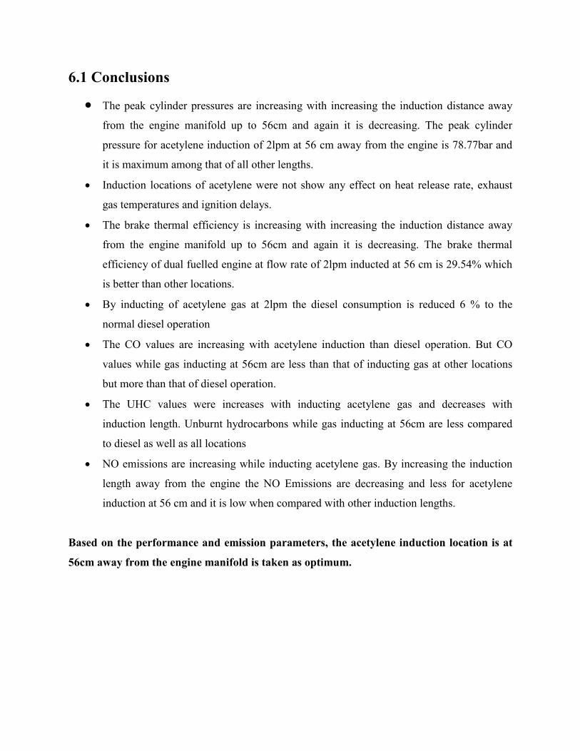
6.1 Conclusions
• The peak cylinder pressures are increasing with increasing the induction distance away
from the engine manifold up to 56cm and again it is decreasing. The peak cylinder
pressure for acetylene induction of 2lpm at 56 cm away from the engine is 78.77bar and
it is maximum among that of all other lengths. • Induction locations of acetylene were not show any effect on heat release rate, exhaust
gas temperatures and ignition delays.
• The brake thermal efficiency is increasing with increasing the induction distance away
from the engine manifold up to 56cm and again it is decreasing. The brake thermal
efficiency of dual fuelled engine at flow rate of 2lpm inducted at 56 cm is 29.54% which
is better than other locations.
• By inducting of acetylene gas at 2lpm the diesel consumption is reduced 6 % to the
normal diesel operation
• The CO values are increasing with acetylene induction than diesel operation. But CO
values while gas inducting at 56cm are less than that of inducting gas at other locations
but more than that of diesel operation.
• The UHC values were increases with inducting acetylene gas and decreases with
induction length. Unburnt hydrocarbons while gas inducting at 56cm are less compared
to diesel as well as all locations
• NO emissions are increasing while inducting acetylene gas. By increasing the induction
length away from the engine the NO Emissions are decreasing and less for acetylene
induction at 56 cm and it is low when compared with other induction lengths.
Based on the performance and emission parameters, the acetylene induction location is at
56cm away from the engine manifold is taken as optimum.
• The peak pressure is increasing with increased flow rate of acetylene due to instantaneous
combustion of gaseous fuel in first stage of combustion.
• The brake thermal efficiency for 3lpm of acetylene induction is 30.99% and is more than
that of diesel operation and other flow rates of acetylene induction.
• Exhaust gas temperatures are increasing with increasing acetylene flow rates as peak
pressures are increasing and heat input also increasing with increasing flow rate.
• Volumetric efficiency is continuously decreasing along with the flow rates as some
amount of intake air is replaced by acetylene gas.
• CO levels are increasing with acetylene induction flow rates as it replaces intake air and
leads to unavailability of sufficient air for proper combustion. Those values are low at
3lpm flow rate than other flow rates.
• UHC levels are increasing with acetylene flow rates due to improper combustion. Flow
rate of 3lpm is getting lower UHC when compared to other flow rates.
• NO values are lesser for acetylene induction at low loads and higher than diesel at full
loads. The NO value for 3lpm is less than that of other flow rates of acetylene.
• Smoke levels are decreasing with acetylene flow rates marginally.
• The energy share of acetylene at a flow rate of 3lpm is 18.5 % at full load and it reduces
19.5% of diesel consumption.
Based on performance and emission parameters, the optimum flow rate of acetylene
induction is 3lpm.
6.2 Future Work In the present investigation the acetylene induction location and induction flow rate was
optimized experimentally for the single cylinder, 4 stroke, air cooled diesel engine. But the
present investigation is useful for only single cylinder engine having same technical
specifications. Some mathematical proof has to be derived for the present work and incorporated
for the high level engine and for different gaseous fuels. The mixing strength of gaseous fuel
while inducting along with air has to be checked by CFD analysis and suggest the best location
of induction for proper mixing of gaseous fuels with air that will avoid carburetor arrangement.

CHAPTER 7
REFERENCES

1) G.Nagarajan, T.Lakshmanan, Experimental Investigation on Dual Fuel Operation of Acetylene in a DI Diesel Engine, fuel processing technology 91(2010)496-503.
2) S.Swami Nathan, J.M.Mallikarjuna, A.Ramesh, Effect of charge temperature and exhaust gas re-circulation on combustion and emission characteristics of acetylene fuelled HCCI engine, Fuel89(2010)515-521
3) T.Lakshmanan, G.Nagarajan, Performance and Emission of Acetylene-aspirated diesel engine, vol3,number 2,june 2009,Jordan journal of mechanical and industrial engineering
4) wulff et al, Dual Fuel composition including acetylene for use with diesel and other internal combustion engines, patent no: US 6,287,351 B1,patent date:Sep11,2001
5) Okjoo Park, Peter S.Veloo et al., Combustion characteristics of alternative gaseous fuels,. proceedings of combustion institute (2010).
6) T.Lakshmanan, G.Nagarajan, Experimental investigation of timed manifold injection of acetylene in direct injection diesel engine in dual fuel mode, Energy 35(2010),3172-3178
7) T.Lakshmanan, G.Nagarajan, Study on using acetylene in dual fuel mode with exhaust gas recirculation, Energy 2011, 1-7.
8) John W.H.Price, An acetylene cylinder explosion: A most probable cause analysis , Engineering Failure Analysis 13 (2006) 705–715
9) T.Lakshmanan, G.Nagarajan, Experimental investigation of port injection of acetylene in DI diesel engine in dual fuel mode, Energy 2011.
10) Performance evaluation of a dual fuel engine(Diesel+LPG), G.A.Rao, A.V.S.Raju et al. Indian Journal of Science and Technology, vol no:3, march 2010
11) K.Sudheesh, K.M.Mallikarjuna, Effect of cooling water flow direction on performance of an acetylene fuelled HCCI engine, Indian journal of engineering and material sciences, vol 17, apr 2010, pp79-85
12) B.B.Sahoo, N.Sahoo et al. Effect of engine parameters and type of gaseous fuel on the performance of dual-fuel gas diesel engine- A critical Review, Renewable and sustainable energy reviews13(2009) 1151-1184.
13) Mohamed Y.E.Selim, Sensitivity of dual fuel engine combustion and knocking limits to gaseous fuel composition, Energy Conversion and Management 45(2004)411-425
14) Mohamed Y.E.Selim , Effect of engine parameters and gaseous fuel type on the cyclic variability of dual fuel engines, Fuel 84 (2005) 961–971

15) G.A. Karim, N.P.W. Moore, The knock in dual-fuel engines- Proc Instn Mech Engrs, Vol. 181, 1966-67, 453-466.
16) H.E. Saleh, Effect of variation in LPG composition on emissions and performance in a
dual fuel diesel engine, Fuel 87 (2008) 3031–3039
17) L.M. Das, Hydrogen engine research and development (R&D) programs in Indian Institute of Technology (IIT). Int. J. Hydrogen Energy, Vol. 27, 2002, 953-965
18) M. Senthil Kumar et al, Use of hydrogen to enhance the performance of a vegetable oil fuelled compression ignition engine-�International Journal of Hydrogen Energy 28 (2003) 1143–1154
19) Stanislaw Szwaja, Karol Grab-Rogalinski, Hydrogen combustion in a compression ignition engine, international journal of hydrogen energy 34 (2009) 4413–4421
20) C.M. White, R.R. Steeper, A.E. Lutz, The hydrogen-fueled internal combustion engine: a technical review- International Journal of Hydrogen Energy 31 (2006) 1292 – 1305
21) Murari Mohon Roy, Eiji Tomita, Nobuyuki Kawahara, Yuji Harada, Atsushi Sakane, Performance and emission comparison of a supercharged dual-fuel engine fueled by producer gases with varying hydrogen content, international journal of hydrogen energy34(2009) 7811–7822
22) M.A. Escalante Soberanis, A.M. Fernandez, A review on the technical adaptations for internal combustion engines to operate with gas/hydrogen mixtures- international journal of hydrogen energy xxx(2009)1–7
23) L.M.Das, Fuel induction techniques for a hydrogen operated engine, International Journal Hydrogen Energy, vol 15 no11 pp 833-842,1990
24) V Edwin Geo et.al, Studies on dual fuel operation of rubber seed oil and its bio diesel with hydrogen as inducted fuel, International Journal Hydrogen Energy 33(2008) 6357-6367
25) N.R.Banapurmath et al, Experimental investigations of a four-stroke single cylinder direct injection diesel engine operated on dual fuel mode with producer gas as inducted fuel and honge oil and its methyl ester(HOME) as injected fuels, Renewable Energy 33 (2008) 2007-2018.
26) K.Purushotham et.al, Performance ,combustion and emission characteristics of compression ignition engine operating on neat orange oil, Renewable Energy 34 (2009) 242–245
27) Ganesan V. Internal combustion engine. 3rd ed. Singapore: McGraw Hill Book Company; 2007

28) Heywood JB. Internal combustion engine fundamentals. Singapore: McGraw Hill Book
Company; 1998
29) R.K.Rajput, Thermal Engineering, seventh edition
30) Website-http://encyclopedia.airliquide.com.


