Optimization of Axial Compressor for the instability measurement … · 2016-09-09 · Optimization...
5
International Journal of Scientific & Engineering Research, Volume 7, Issue 1, Januar-2016 ISSN 2229-5518 IJSER © 2016 http://www.ijser.org Optimization of Axial Compressor for the instability measurement of Fluid MU SOHAIL (M.Umer Sohail) Abstract—Control and Modeling for stall and surge phenomenon in axial flow compressors have received great importance in recent times. In power generation plant and aerospace propulsion compression system are prone to the aerodynamic instabilities of stall and surge. In aero engine compressors higher pressure ratio has always been a growing stipulates which has over involved by diverse rotating stall and surge of aerodynamic instability. Due to interrupted mass flow variation in compressor, plenum, throttle i.e. in whole pumping system, surge may occur. Stall can be described by a wave travelling about the boundary of the machine. Blades become overheated due to decrease of pressure rise in the compressor, which is being caused by fluid instabilities i.e. stall and surge. These instabilities of fluid result mechanical damage to the compressor. The objectives of this research are to restrain stall and surge, to enlarge steady working of the axial flow compressors and to expand the stable fluid flow. This review report surveys the most recent optimization research literature on stall and surge effects in axial compressor. Success of this research field will significantly improve the efficiency of the axial compressor and aero-engine performance in future. Index Terms—Bifurcation analysis, FDM, Compressor Flow chart , Centrifugal Compressor, Axial Flow compressor, FDM, Moore-Greitzer Model (MGM), Multiple Time Scale (MTS) —————————— —————————— 1 INTRODUCTION Compressor is a mechanical instrument which employs high pressure of compressible fluid during the channel of the fluid through the compressor by decreasing the fluid specific volume. Compressor fundamental objective is to transport fluid at higher pressure by compressing the fluid than its orig- inal pressure. Compressor is classified as positive displace- ment and dynamic compressor. A rise in pressure prior to dis- charge occurred in positive displacement compressor in such a way when specified amount of fluid is allowed to enter in a compressor for compression and volume is mechanically de- creased. The air flow remains fundamentally stable with varia- tion in discharge pressure at steady speed e.g. reciprocating compressor, vane compressors and rotary compressors [3] Figure 1(Compressor flow char) When the impellers rotate at very high speeds velocity energy is being imparted to continuously flowing fluid in dynamic compressors. Impellers and discharge diffusers changes veloc- ity energy into pressure energy. Dynamic compressor consists of centrifugal compressors and axial compressors. Compres- sion is achieved in centrifugal compressor by applying inertial forces to the gas by means of rotating impellers. A centrifugal compressor consists of one of more stages. Each stage consists of rotating element and stationary element i.e. impeller and diffusers respectively. In centrifugal compressor, fluid enters the impellor axially and discharges radially at right angle to the axis of rotation. Centrifugal compressors are used in heli- copter and small aircraft applications because it has higher single-stage pressure ratio than axial compressors [4] Figure 2 (Centrifugal Compressor) 2 AXIAL FLOW COMPRESSOR Particularly above 5 Megawatt axial compressors are most- ly used in gas turbine purpose. In axial flow compressor fluid enters the compressor and also exits from the gas turbine in ———————————————— M.Umer Sohail is currently pursuing PhD degree in Aerospace engineering in IST, Pakistan, PH-0092-3445266876. E-mail: [email protected] 828 IJSER
Transcript of Optimization of Axial Compressor for the instability measurement … · 2016-09-09 · Optimization...

International Journal of Scientific & Engineering Research, Volume 7, Issue 1, Januar-2016 ISSN 2229-5518
IJSER © 2016
http://www.ijser.org
Optimization of Axial Compressor for the instability measurement of Fluid
MU SOHAIL (M.Umer Sohail)
Abstract—Control and Modeling for stall and surge phenomenon in axial flow compressors have received great importance in recent
times. In power generation plant and aerospace propulsion compression system are prone to the aerodynamic instabilities of stall and
surge. In aero engine compressors higher pressure ratio has always been a growing stipulates which has over involved by diverse rotating
stall and surge of aerodynamic instability. Due to interrupted mass flow variation in compressor, plenum, throttle i.e. in whole pumping
system, surge may occur. Stall can be described by a wave travelling about the boundary of the machine. Blades become overheated due
to decrease of pressure rise in the compressor, which is being caused by fluid instabilities i.e. stall and surge. These instabilities of fluid
result mechanical damage to the compressor. The objectives of this research are to restrain stall and surge, to enlarge steady working of
the axial flow compressors and to expand the stable fluid flow. This review report surveys the most recent optimization research literature
on stall and surge effects in axial compressor. Success of this research field will significantly improve the efficiency of the axial compressor
and aero-engine performance in future.
Index Terms—Bifurcation analysis, FDM, Compressor Flow chart , Centrifugal Compressor, Axial Flow compressor, FDM, Moore-Greitzer
Model (MGM), Multiple Time Scale (MTS)
—————————— ——————————
1 INTRODUCTION
Compressor is a mechanical instrument which employs
high pressure of compressible fluid during the channel of the
fluid through the compressor by decreasing the fluid specific
volume. Compressor fundamental objective is to transport
fluid at higher pressure by compressing the fluid than its orig-
inal pressure. Compressor is classified as positive displace-
ment and dynamic compressor. A rise in pressure prior to dis-
charge occurred in positive displacement compressor in such a
way when specified amount of fluid is allowed to enter in a
compressor for compression and volume is mechanically de-
creased. The air flow remains fundamentally stable with varia-
tion in discharge pressure at steady speed e.g. reciprocating
compressor, vane compressors and rotary compressors [3]
Figure 1(Compressor flow char)
When the impellers rotate at very high speeds velocity energy
is being imparted to continuously flowing fluid in dynamic
compressors. Impellers and discharge diffusers changes veloc-
ity energy into pressure energy. Dynamic compressor consists
of centrifugal compressors and axial compressors. Compres-
sion is achieved in centrifugal compressor by applying inertial
forces to the gas by means of rotating impellers. A centrifugal
compressor consists of one of more stages. Each stage consists
of rotating element and stationary element i.e. impeller and
diffusers respectively. In centrifugal compressor, fluid enters
the impellor axially and discharges radially at right angle to
the axis of rotation. Centrifugal compressors are used in heli-
copter and small aircraft applications because it has higher
single-stage pressure ratio than axial compressors [4]
Figure 2 (Centrifugal Compressor)
2 AXIAL FLOW COMPRESSOR
Particularly above 5 Megawatt axial compressors are most-
ly used in gas turbine purpose. In axial flow compressor fluid
enters the compressor and also exits from the gas turbine in ————————————————
M.Umer Sohail is currently pursuing PhD degree in Aerospace engineering in IST, Pakistan, PH-0092-3445266876. E-mail: [email protected]
828
IJSER
International Journal of Scientific & Engineering Research, Volume 7, Issue 1, Januar-2016 ISSN 2229-5518
IJSER © 2016
http://www.ijser.org
axial direction. The axial flow compressors have higher cross
sectional flow area per mass flow rate and also possess lower
frontal areas i.e. diameter. The efficiency of axial flow com-
pressor is quite higher than the centrifugal compressor thus it
is generally being given more preference over centrifugal
compressors. When high intake volume of flow is required
and also when head required is low than axial compressors
are ideal under these circumstances [5]. Gases or fluid are be-
ing continuously pressurized in an axial flow compressor. Ax-
ial flow is airfoil rotating based compressor where fluid enters
and leaves axially in the compressor. Therefore it is different
from centrifugal and mixed flow compressors where fluid
flows radially to the compressor. In axial compressors rotor
blades wield torque on the fluid which amplifies the velocity
of the fluid as it flows through the compressor. To achieve a
large pressure rise several rows of airfoils are required in axial
compressor that also make them more complex [6]. Fluid is
compressed in axial flow compressor to obtain high pressure
ratio by first accelerating and then diffusing the fluid. Fluid is
initially accelerated in rotor which is a row of rotating blades.
This accelerated fluid is than diffused into the stator where
velocity increase gained is being converted into pressure in-
crease. There are numerous stages of compressor. Stage is the
combination of rotor followed by stator. IGV (Inlet Guide
Vanes) are further rows of stationary blades that are used in
compressor inlet. IGV are used to ensure that at desired flow
angles fluid penetrates in the first stage rotor [7]. For the fluc-
tuating flow requirement of the engine, Inlet Guided Vanes
are also pitching variable so that it can be adjusted. At the exit
of the compressor EGV’s is another diffuser. The basic pur-
pose of the EGV is to control fluid velocity entering the com-
bustors [8]. There are two parameters in which gas turbine
depends. First is increase in pressure ratio as well as second is
raise in firing temperature [9]
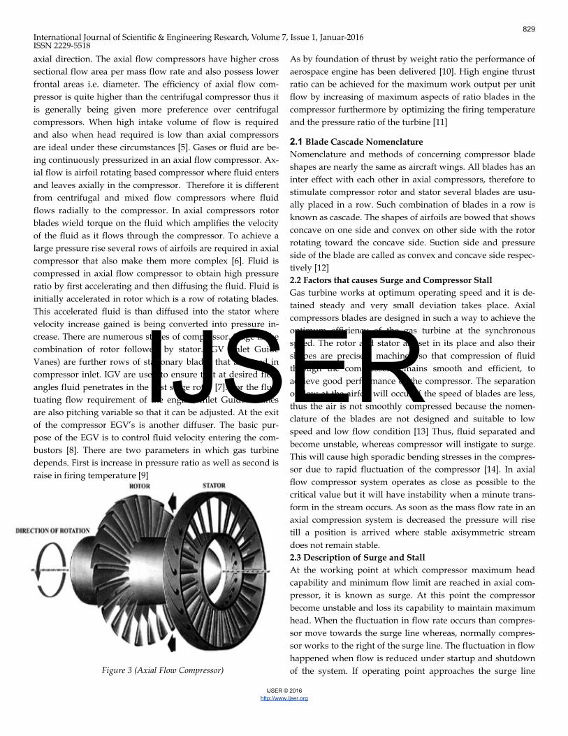
Figure 3 (Axial Flow Compressor)
As by foundation of thrust by weight ratio the performance of
aerospace engine has been delivered [10]. High engine thrust
ratio can be achieved for the maximum work output per unit
flow by increasing of maximum aspects of ratio blades in the
compressor furthermore by optimizing the firing temperature
and the pressure ratio of the turbine [11]
2.1 Blade Cascade Nomenclature
Nomenclature and methods of concerning compressor blade
shapes are nearly the same as aircraft wings. All blades has an
inter effect with each other in axial compressors, therefore to
stimulate compressor rotor and stator several blades are usu-
ally placed in a row. Such combination of blades in a row is
known as cascade. The shapes of airfoils are bowed that shows
concave on one side and convex on other side with the rotor
rotating toward the concave side. Suction side and pressure
side of the blade are called as convex and concave side respec-
tively [12]
2.2 Factors that causes Surge and Compressor Stall
Gas turbine works at optimum operating speed and it is de-
tained steady and very small deviation takes place. Axial
compressors blades are designed in such a way to achieve the
optimum efficiency of the gas turbine at the synchronous
speed. The rotor and stator are set in its place and also their
shapes are precisely machined so that compression of fluid
through the compressor remains smooth and efficient, to
achieve good performance of the compressor. The separation
of flow at the airfoil will occur if the speed of blades are less,
thus the air is not smoothly compressed because the nomen-
clature of the blades are not designed and suitable to low
speed and low flow condition [13] Thus, fluid separated and
become unstable, whereas compressor will instigate to surge.
This will cause high sporadic bending stresses in the compres-
sor due to rapid fluctuation of the compressor [14]. In axial
flow compressor system operates as close as possible to the
critical value but it will have instability when a minute trans-
form in the stream occurs. As soon as the mass flow rate in an
axial compression system is decreased the pressure will rise
till a position is arrived where stable axisymmetric stream
does not remain stable.
2.3 Description of Surge and Stall
At the working point at which compressor maximum head
capability and minimum flow limit are reached in axial com-
pressor, it is known as surge. At this point the compressor
become unstable and loss its capability to maintain maximum
head. When the fluctuation in flow rate occurs than compres-
sor move towards the surge line whereas, normally compres-
sor works to the right of the surge line. The fluctuation in flow
happened when flow is reduced under startup and shutdown
of the system. If operating point approaches the surge line
829
IJSER

International Journal of Scientific & Engineering Research, Volume 7, Issue 1, Januar-2016 ISSN 2229-5518
IJSER © 2016
http://www.ijser.org
than the impeller instigate to work in stall and recirculation of
flow begins. [15]. Operational changes should be made by us-
ing control system to operate the compressor out of the surge
line. Otherwise surge cycle will keep on repeating itself [16].
The flows can be on the whole categorized as stable rotating
stall, deep surge & classic surge. Part of the compressor annu-
lus operates in stalled flow when the machine experiences
rotating stall [17]. This is also referred as stall cell. Almost half
of the wheel speed stall cell rotates around the annulus. If the
pressure rises, average mass flow remains constant and flow
also remains steady than there will have steady rotating stall
whereas flow moves in a context with the stall cell [18]. Steady
rotating stall has lower pressure ascend than the design point
[19]. Surge is a variation of mass flow & pressure rise along
the length of axial compressor [20], with a frequency inferior
to related by channel of a stall cell.
3 FLUID DYNAMIC MODEL
Numerous considerations have been dedicated for the re-
search of airflow & turbo-machine combustion because when
a turbo machines works close to optimal working value and
parameter the flow became unstable. Large stress on the en-
gine has been developed due to these instabilities. To facilitate
recuperate the original operations from these instabilities
sometimes engine needs to be turned off. Thus to avoid these
circumstances presently jet engines are being run away from
optimal operating values. But, when they are run away from
optimal parameter values they consume more fuel and engine
weight [21]. The performance of axial flow compressors is be-
ing limited due to fluid dynamic instabilities such as rotating
stall and surge. Consider the schematic of the axial compres-
sion system. It consists of a compressor, a pipe leading the free
stream flow into a plenum, a plenum, throttle and its exit duct.
In this model for the description of pressure rise the compres-
sor is replaced by the combination of actuator disk and a con-
stant area duct having length “Lc”. Similarly throttle is also
replaced by the combination of actuator disk and a constant
area duct having length “Lt” [22]
Figure 4 (FDM "\control volume for the compression system")
The following hypotheses are taken in considerations before
going on the derivation of the model. A situation, in which
any of these assumptions is no more valid, can bring the re-
sults from the model in question.
The oscillations happening in the structure have been modeled
to those of a Helmholtz resonator. It describes as all the K.E of
oscillation is possessed by the fluid motion in the compressor
and throttle ducts whereas all the P.E is possessed in the ple-
num by the compression of the gas.
Low Inlet Mach number is being subjected to the compression
system. Thus as compare to the ambient pressure, pressure
rises are minute. As the oscillation related to surge is usually
associated as reasonably low frequency, thus the flow in the
duct is incompressible having density taken as equal to the
ambient value. Thus at any instant all the fluid particles will
have the same axial velocity in one of these ducts. It means it
will have fully developed flow.
Area of the plenum is larger than the compressor duct, thus
velocities and fluid accelerations in the plenum are insignifi-
cant [23] Whereas pressure in the plenum is assume to be uni-
form spatially, but changing with time.
The flow field is considered as irrotational
The effects of viscosity have not been taken into account.
Body forces acting on the control volume have not been con-
sidered.
The inertia in the throttle duct has been neglected. This is gen-
erally a good assumption since throttle curves are usually
steep and the fluctuations in mass flow rate of throttle are
smaller than those through the compressor.
The flow is considered to be one-dimensional, and only the axial component of velocity is responsible for the transport processe.
4 BIFURCATION OF THE SURGE AND ROTATING STALL
During the research of axial compressors a very significant di-
lemma arises while flow instability that either it will experi-
ence rotating stalls or surge. To analyze this dilemma linear
compression system model was being investigated by
Greitzer. He accomplished that for a specified compressor sys-
tem there is a non dimensional parameter. The system re-
sponse is depended on this NDP. This parameter is denoted
by “B” [24]
The value of B” is the compressor characteristics which verify
the mode of instability. If the value of B lies above than the
critical value than it will exhibit surge oscillation. If the value
of B lies lower than the critical value than it will reveal initial
transient to the steady flow [25]
Here,
830
IJSER

International Journal of Scientific & Engineering Research, Volume 7, Issue 1, Januar-2016 ISSN 2229-5518
IJSER © 2016
http://www.ijser.org
a = speed of sound
U = rotor speed
Lc = effective length of compressor duct
Ac = compressor flow area
Vp = Plenum Volume
5 BRIEF OF POST STALL:
To explain post stall, Greitzer developed two dimensional theories in axial compression system that elaborate the devel-opment of rotating stall amplitude, mass flow and pressure rise during compression. He investigated that both surge and rotating stall exit in equilibrium form. This concluded that amplitude of rotating stall during steady state is dissimilar from unsteady flow. Thus in both cases performance of the compressor differs instantaneously. Furthermore it was also analyzed that surge and rotating stall of the system not only depends upon the parameter of “B” but also depends upon the length to radius of the radius of the compressor. Higher the value of B, higher will be the surge and vice versa.
.
6 MOORE- GREITZER MODEL:
For the understanding the mechanism of fluid instabilities
numerous models and methods have been proposed. Moore-
Greitzer model is one of the renowned and universally accept-
ed models to understand the mechanism of fluid instabilities.
It comprises of compressor working in a channel & discharg-
ing to a downstream plenum [26]. The dimension of plenum is
larger than compressor and its duct so that in plenum velocity
and fluid acceleration is negligible considered. The pressure in
the plenum is uniform at probably changeable in instance. At
the plenum exit the flow is constrained by the throttle.
7 STABILITY OF AXIAL FLOW COMPRESSOR
Various techniques have been examined and introduced for
axial compressor fluid stability and rotor casing treatment
such as passive control techniques (PCT) and active control of
rotating stall (ACRS). PCT by using screen is being carried out
to manage the flow disorder ingoing in the compressor. By
using this technique, it has increased stable flow range as well
as peak pressure rise up to 15% to 20%. In Axial compressor
for rotor casing treatment, over the tips of rotors consist of
groves. ACRS consist of two approaches. 1st approach is
based on the control of model wave, whereas 2nd approach is
based on simulating the flow directly into the rising stall cell.
Greitzer introduced an air injection system by developing a
range of separately controlled valves. These controlled valves
are installed near the tips of the first rotor where stall cells
generally first appears and all these controlled valves are
equally spaced from each other.
8 CONCLUSIONS
This work is deduced, after studying and analysed different
authors/ researchers work on the axial compressor instability.
The generalized effect of compressor characteristic under cu-
bic nonlinearity on the behavior of Limit Cycle Oscillations
has been measured. By means of MTS method, estimated solu-
tions are obtained. From these solutions, stability criterion and
the necessary condition for sustained limit cycle oscillations is
derived. Salient results concluded from this research are listed
as under
The behavior of surge oscillations is significantly dependent
on the choice of compressor characteristic. By treating the
compressor characteristic used in the MGM in a generic man-
ner, it has been found that a small change in and β effects
the dynamics of the system significantly. The amplitude of
surge oscillations exhibits supercritical bifurcation for the sta-
ble limit cycle.
Method of Multiple Time Scales has successfully captured the quali-
tative and quantitative aspects of the surge phenomena. The analyti-
cal solution obtained via MTS method is well in agreement with the
numerical solution.
References
[1] N Ananthkrishnan. "Global stability and control analysis of axial compressor
stall and surge phenomena using bifurcation methods”, Proceedings of the
Institution of Mechanical Engineers Part A Journal of Power and Energy, 2003
[2] M. Alamir. "Nonlinear robust controller for rotating stall and surge in axial
flow compressors", Proceedings of the 39th IEEE Conference on Decision and
Control (Cat # 00CH37187), 2000
[3] Mulyandasari, V. (2008, March). KLM Technology. Retrieved from
http://www.scribd.com/doc/131820344/Engineering-Design-Guidelines-
Compressors-KLM-Technology-group#scribd
Figure 5Moore-Greitzer Model)
831
IJSER

International Journal of Scientific & Engineering Research, Volume 7, Issue 1, Januar-2016 ISSN 2229-5518
IJSER © 2016
http://www.ijser.org
[4] Mulyandasari, V. (2011). Johor Bahru, Malaysia: KLM TECHNOLOGY
GROUP
[5] Anthony Giampaolo. (2006). Gas Turbine Handbook : Principles and Practic-
es (Vol. 3rd). India: The Fairmont Press, Inc.
[6] Avinash. (2014). tractionmech8. Retrieved from
https://tractionmech8.wordpress.com/2014/04/page/4
[7] P.Boyce, D. M. (n.d.). Chaoter 2. In Axial Flow Compressors Gas Turbine
Engineering handbook, 2012
[8] www.docstoc.com
[9] seca.doe.gov
[10] Boyce, Meherwan “An Overview of Gas Turbines”. Gas Turbine Engineer-
ing, 2012
[11] www.netl.doe.gov
[12] P.Boyce, D. M. (n.d.). Chaoter 2. In Axial Flow Compressors (p. chapter 2).
[13] Emirates Aviation College, Aerospace & Academia Studies
[14] Pawan. (2012, January 28). Retrieved December 13, 2014, from control.com:
http://www.control.com/thread/1327739889
[15] Ghanlbariannaeeni Ali Ghazanfarihashemi “Protecting a compressor from
surge”, 2012
[16] Short, Marsha (2008). Application Guideline for Centrifugal Compressor
Surge Control Systems.
[17] F.E. McCaughan. “Bifurcation Analysis of Axial Flow Compressor Stability”
SIAM Journal on Applied Mathematics, 1990
[18] Bjorn Birnir,”Basic Control for the Viscour Moore-Greitzer Partial Differential
Equation” SIAL Journal on control and Optimization, 2000
[19] McCaughan, F.E., and Hong Xiao Xue. “Stability of fully Developed Rotating
Stall” Volume 1 Turbomachinery, 1992
[20] Badmus, “Nonlinear control of surge in axial compression system”,
[21] Bjorn Birnir, S. H. (n.d.). Derivation of the Viscus Moore-Greitzer Equation for
Aeroengine Flow.
[22] Sivaramkrishnan Malathi, Ananth and A. Kushari. “A Parametric Investiga-
tion of Geometric Variation on Fluid Dynamic Instabilities in Axial Compres-
sion Systems” International Journal of rotating machinery, 2012
[23] Amit Kumar, N. B Ananathkrishnan “Mutimodel Solutions to Augmented
Moore-Greitzer Model and Rotating Stall”. 43rd AIAA Aerospace Science
Meeting and Exhit., 2005
[24] Sean Humbert, A. K. (1998). Dynamics and Control of entrained solutions in
multi-mode Moore Greitzer Model
[25] M.Ismail. (1995). Rotating stall in axial flow compressor.
[26] HU, Jun and Leonhard Fottner. “Calculations of Effetcs of Rotating Inlet Dis-
tortion on Flow Instabilities in Compression Systems” 1995
[27] Robert Biollo and Ernesto Benini “Recent advances in transonic axial com-
pressors aerodynamics” 2013
Further References: [28] Ramnath, R.V., Multiple Scales Theory and Aerospace Applications. AIAA
Education Series, ed. J.A. Schetz. 2010: American Institute of Aeronautics and
Astronautics, Inc.
[29] Maqsood, A. and T.H. Go, Multiple time scale analysis of aircraft longitudinal
dynamics
with aerodynamic vectoring. Nonlinear Dynamics, 2012. 69: p. 731–742. 27.
Greitzer, E.M. and F.K. Moore, A Theory of Post-Stall Transients in Axial
Compression
Systems: Part II–Application. Journal of Engineering for Gas Turbines and
Power, April 1986
832
IJSER