Optimization of Air Induction System for Acoustic Performance · Optimization of Air Induction...
16
Optimization of Air Induction System for Acoustic Performance Sri Siva Sai Meduri QuEST Global Services Pte Ltd Sundaram V, Sathish Kumar S FCA Engineering India Pvt Ltd GT CONFERENCE INDIA 2015 – Pune, India. Dec 07, 2015. ©2015 FCA US LLC
Transcript of Optimization of Air Induction System for Acoustic Performance · Optimization of Air Induction...

Optimization of Air Induction System for Acoustic Performance Sri Siva Sai Meduri QuEST Global Services Pte Ltd
Sundaram V, Sathish Kumar S FCA Engineering India Pvt Ltd
GT CONFERENCE INDIA 2015 – Pune, India.
Dec 07, 2015.
©2015 FCA US LLC
Agenda
2
Overview
About Air Induction system
Engine Model Validation
Build Air Induction System
Transmission Loss Simulation
Snorkel Noise Simulation
Optimization of Air Induction system
Testing the Optimized Model
Results and Conclusion
©2015 FCA US LLC Dec 07, 2015 GT CONFERENCE INDIA 2015

Overview
3
Here we discuss the design and optimization of air induction
system for better NVH performance.
1D model is build and simulated for transmission loss and snorkel
noise in GT-POWER.
Key factors which control the design of air induction system to
attenuate the noise are identified during simulation.
Optimized air induction system model is developed for a chosen
engine noise.
©2015 FCA US LLC Dec 07, 2015 GT CONFERENCE INDIA 2015

About Air Induction system
4
Air Induction System fulfil a number of roles in an overall vehicle design
which are:
channel air to the engine;
filter particulates;
enhance engine performance through wave action tuning;
reduce noise.
• Clean Air
• Volumetric efficiency
Engine Performance
Air Induction System Design
• Less cabin noise
• Meet Regulatory norms
Acoustics
©2015 FCA US LLC Dec 07, 2015 GT CONFERENCE INDIA 2015

1D Modeling Flow Chart
5
Fig. 1D simulation Flow Chart
Design
CAD data 1D
Simulation Optimization
Testing Good
Correlation
Post
Process
Yes
Optimized
Design
No
Meeting the
Targets
Tune the system
Not Meeting the
Targets

Engine Model Validation
6
Engine GT-POWER Model is validated for the following parameters:
Volumetric efficiency
Brake power, Brake torque
Air flow rate, Gas flow rate
Gas flow temperature and others.
Throttle body
Intake
Manifold
Engine crank train
Exhaust
system
• Air Induction system to be added at throttle entry.
©2015 FCA US LLC Dec 07, 2015 GT CONFERENCE INDIA 2015
7
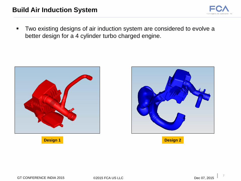
Build Air Induction System
Two existing designs of air induction system are considered to evolve a
better design for a 4 cylinder turbo charged engine.
Design 1 Design 2
©2015 FCA US LLC Dec 07, 2015 GT CONFERENCE INDIA 2015

8
Build Air Induction System Cont..
GEM3D
Shell
Discretization
©2015 FCA US LLC Dec 07, 2015 GT CONFERENCE INDIA 2015
GEM3D
General Flow Split
Discretization
Shell Discretization
• More Effective way to do acoustic analysis for
accurate results at higher frequency
• Time consumed to run the system level analysis
is more.
Flow Split Discretization
• Good enough to do acoustic analysis for
accurate results at low and mid range
frequency.
• Time consumed to run the system level
analysis is less.

9
Build Air Induction System Cont..
©2015 FCA US LLC Dec 07, 2015 GT CONFERENCE INDIA 2015
GT-ISE GEM3D
The dirty side, clean side ducts are modelled as pipe components. The air filter
box and resonators are modelled as flow split components.
Design 1
Design 2
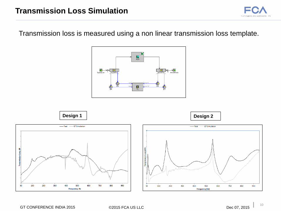
Transmission Loss Simulation
10
Transmission loss is measured using a non linear transmission loss template.
Design 1 Design 2
©2015 FCA US LLC Dec 07, 2015 GT CONFERENCE INDIA 2015
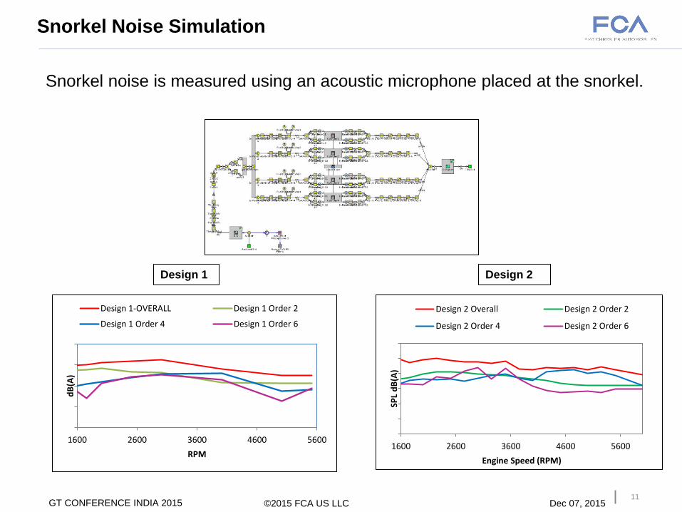
Snorkel Noise Simulation
11
Snorkel noise is measured using an acoustic microphone placed at the snorkel.
Design 1 Design 2
©2015 FCA US LLC Dec 07, 2015 GT CONFERENCE INDIA 2015
1600 2600 3600 4600 5600
SPL
dB
(A)
Engine Speed (RPM)
Design 2 Overall Design 2 Order 2
Design 2 Order 4 Design 2 Order 6
1600 2600 3600 4600 5600
dB
(A)
RPM
Design 1-OVERALL Design 1 Order 2
Design 1 Order 4 Design 1 Order 6
12
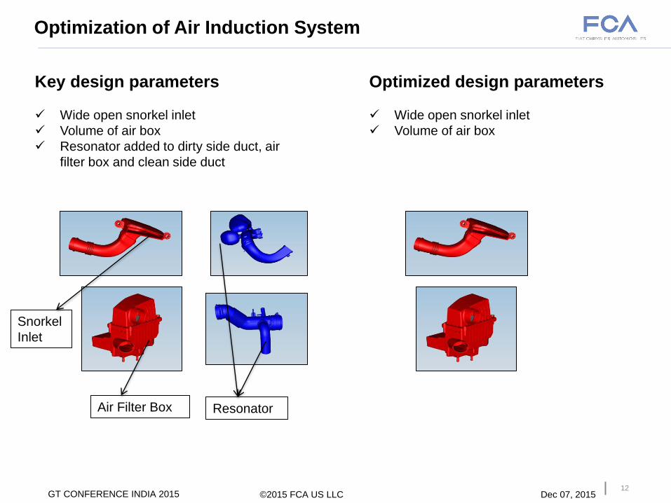
Key design parameters
Wide open snorkel inlet
Volume of air box
Resonator added to dirty side duct, air
filter box and clean side duct
Optimization of Air Induction System
©2015 FCA US LLC Dec 07, 2015 GT CONFERENCE INDIA 2015
Optimized design parameters
Wide open snorkel inlet
Volume of air box
Resonator Air Filter Box
Snorkel
Inlet
13
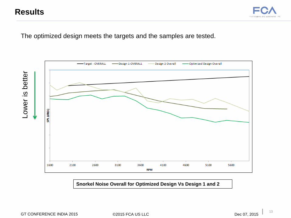
Results
The optimized design meets the targets and the samples are tested.
Snorkel Noise Overall for Optimized Design Vs Design 1 and 2
Low
er
is b
ett
er
©2015 FCA US LLC Dec 07, 2015 GT CONFERENCE INDIA 2015

14
Results
The optimized design meets the targets and the samples are tested.
Order Snorkel Noise for Optimized Design Vs Design 1 and Design 2
Low
er
is b
ett
er
©2015 FCA US LLC Dec 07, 2015 GT CONFERENCE INDIA 2015
1600 2600 3600 4600 5600
dB
(A)
Engine Speed (RPM)
Design 1 Order 2 Design 2 Order 2
Optimized Design Order 2 Target - OREDER 2
1600 2600 3600 4600 5600
dB
(A)
Engine Speed (RPM)
Design 1 Order 4 Design 2 Order 4
Optimized Design Order 4 Target - ORDER 4
1600 2600 3600 4600 5600
dB
(A)
Engine Speed (RPM)
Design 1 Order 6 Design 2 Order 6
Optimized Design Order 6
1600 2600 3600 4600 5600
SPL
dB
(A)
Engine Speed (RPM)
Design 1 Order 8 Design 2 Order 8
Optimized Design Order 8

15
Conclusion
• 1D Simulation results are in good correlation with test results.
• Key factors to reduce the snorkel noise are identified with transmission loss
and snorkel noise results for the existing designs.
• Design optimization approach detailed here provides best possible combination
of air induction system sub components for a chosen engine.
• This effectively reduces time and cost involved in testing several iterations.
©2015 FCA US LLC Dec 07, 2015 GT CONFERENCE INDIA 2015
16 ©2015 FCA US LLC Dec 07, 2015 GT CONFERENCE INDIA 2015