
Optimization for Unity* Software and Virtual Reality: Run ...
34
Optimization for Unity* Software and Virtual Reality: Run-Time Generated Content by Alejandro Castedo Echeverri Optimizing for high performance has been a constant in game development since the birth of the industry. While developers have always tried to push hardware to its limits, optimization techniques became especially prominent when mobile gaming went mainstream. Popular engines such as Unity* software and Unreal* were originally designed for PC games, and had many shortcomings when designers used them to deliver high-performance experiences on older hardware. New techniques and tricks were required and quickly became commonplace. Today, we are experiencing a similar awakening, with virtual reality (VR) being such a resource-hungry medium that we need to constantly innovate to ensure optimal VR experiences.
Transcript of Optimization for Unity* Software and Virtual Reality: Run ...

Optimization for Unity* Software and Virtual Reality: Run-Time Generated
Content by Alejandro Castedo Echeverri
Optimizing for high performance has been a constant in game development since the birth of the industry. While developers have always tried to push hardware to its limits, optimization techniques became especially prominent when mobile gaming went mainstream. Popular engines such as Unity* software and Unreal* were originally designed for PC games, and had many shortcomings when designers used them to deliver high-performance experiences on older hardware. New techniques and tricks were required and quickly became commonplace. Today, we are experiencing a similar awakening, with virtual reality (VR) being such a resource-hungry medium that we need to constantly innovate to ensure optimal VR experiences.
This article presents techniques that VR developers can use when designing VR experiences and videogames. It also shows the gains that these techniques bring to the table.
Project Overview The work presented utilizes the Unity software engine, but the techniques can be applied in other engines as well. To help you understand performance bottlenecks and find possible solutions, we make use of different performance applications, such as the Unity Profiler, Unity Frame Debugger, and Intel® Graphics Performance Analyzers (Intel® GPA). This project uses a Dell XPS 8910 with an Intel® Core™ i7-6700 processor and an NVIDIA GeForce* GTX 970 graphics processing unit (GPU). This setup is close to the standard minimum specs for PC VR. The software stack uses:
● Unity 2018.1.2f1 ● Simplygon* UI ● Steam*VR plugin for Unity software ● Microsoft Visual Studio* Community ● Intel® GPA
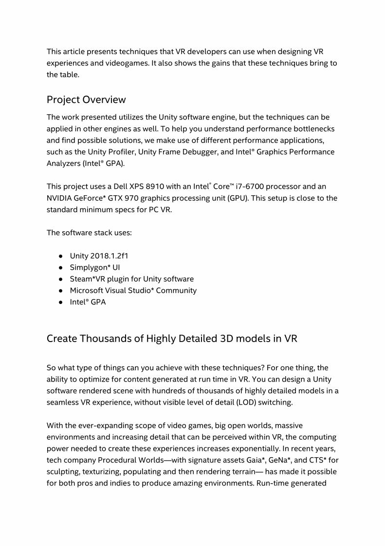
Create Thousands of Highly Detailed 3D models in VR So what type of things can you achieve with these techniques? For one thing, the ability to optimize for content generated at run time in VR. You can design a Unity software rendered scene with hundreds of thousands of highly detailed models in a seamless VR experience, without visible level of detail (LOD) switching. With the ever-expanding scope of video games, big open worlds, massive environments and increasing detail that can be perceived within VR, the computing power needed to create these experiences increases exponentially. In recent years, tech company Procedural Worlds—with signature assets Gaia*, GeNa*, and CTS* for sculpting, texturizing, populating and then rendering terrain— has made it possible for both pros and indies to produce amazing environments. Run-time generated
content akin to the likes of Minecraft* has become a powerful tool to create vast and interesting worlds. You want to be able to move up close to these detailed models in your game world and observe them with clarity. And you want a lot of them.
Figure 1: The goal for this exercise is a Unity* software rendered scene with hundreds of thousands of highly detailed models, in a seamless VR experience.
The project presented here takes advantage of some inherent VR design choices, such as non-continuous locomotion (teleport or similar), even though most of this can be adapted for regular smooth locomotion as well, with a few variations.
Performance Testing Setup
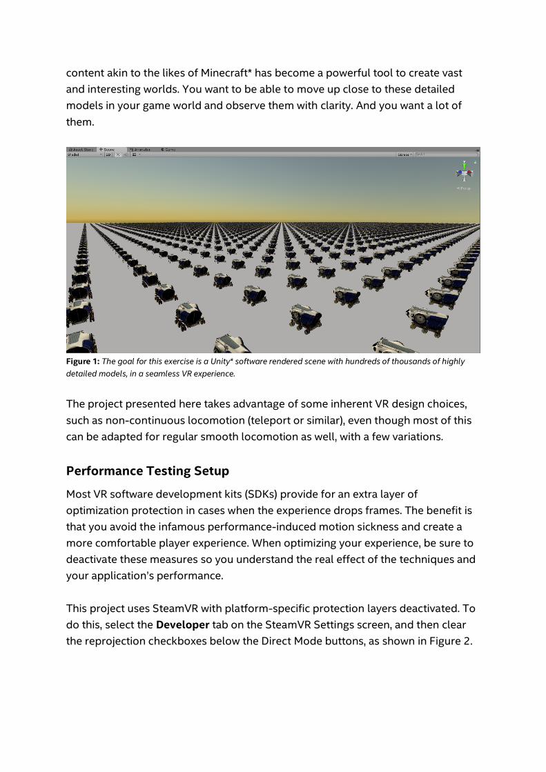
Most VR software development kits (SDKs) provide for an extra layer of optimization protection in cases when the experience drops frames. The benefit is that you avoid the infamous performance-induced motion sickness and create a more comfortable player experience. When optimizing your experience, be sure to deactivate these measures so you understand the real effect of the techniques and your application’s performance. This project uses SteamVR with platform-specific protection layers deactivated. To do this, select the Developer tab on the SteamVR Settings screen, and then clear the reprojection checkboxes below the Direct Mode buttons, as shown in Figure 2.
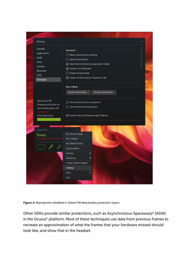
Figure 2: Reprojection disabled in Steam*VR deactivates protection layers. Other SDKs provide similar protections, such as Asynchronous Spacewarp* (ASW) in the Oculus* platform. Most of these techniques use data from previous frames to recreate an approximation of what the frames that your hardware missed should look like, and show that in the headset.

Starting Point: Choosing a Model Selection
This project uses some high-poly, high-definition models to show in VR. Applying an array of techniques, one by one, will further optimize the output generated in Unity software. These models are so heavy and complex that one could expect to be able to show only a handful of them on the screen at the same time. This project focuses on raw, big optimizations. You can do anything presented here with the tools and programming techniques shown. The NASA exploration vehicle is freely available to anyone directly from NASA at the NASA 3D Resources site. The original model is 404,996 polygons. You can see the performance hit that the PC is taking when you add the object in its raw form into an empty scene with directional light. At this point, showing more than three of these exploration vehicles on the screen at the same time will start dropping frames.
Figure 3: NASA exploration vehicle model viewed in Play Mode in Unity* software. Performance statistics can be seen in the upper right corner monitor. You can see that the number of polygons is now much higher than the original. This is due to shader passes. The ship is using the standard shader from Unity software
and a single directional light. Another thing to take into account is the number of draw calls, or batches, that the model requires to be drawn. You can see what’s happening from Intel GPA software in Figure 4. After capturing a frame from its graphics monitor you can analyze it in the graphics frame analyzer.
Figure 4: Intel® GPA Graphics Frame Analyzer reveals draw calls for the NASA exploration vehicle. The Intel® Graphics Frame Analyzer shows more than 200 draw calls for this vehicle. All of the small draw calls for each of the little components of the ship add up. This is problematic when trying to spawn many of the objects on the screen, especially if you are making a mobile VR game. The big blue rectangles are VR-specific steps for the rendering. Unity software automatically batches small meshes before sending them to the GPU, resulting in a considerable number in Saved by Batching. You can, directly in Unity software, combine all the little pieces into one single mesh to reduce the number of draw calls, or you can do it with Simplygon at the same time as you generate LODs. Either way, combining the meshes shows a good improvement for the final goal. Combining meshes reduces the number of draw calls to one, and now the Unity scene doesn’t start dropping frames until you put more than seven spaceships into the scene—this is a 2x improvement already. The design has hit a hard limit, however, as the GPU cannot accept any more polygons and vertices.
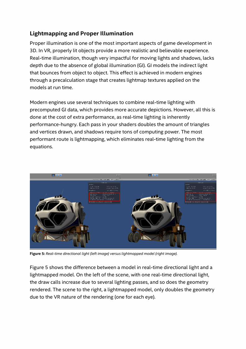
Lightmapping and Proper Illumination Proper illumination is one of the most important aspects of game development in 3D. In VR, properly lit objects provide a more realistic and believable experience. Real-time illumination, though very impactful for moving lights and shadows, lacks depth due to the absence of global illumination (GI). GI models the indirect light that bounces from object to object. This effect is achieved in modern engines through a precalculation stage that creates lightmap textures applied on the models at run time. Modern engines use several techniques to combine real-time lighting with precomputed GI data, which provides more accurate depictions. However, all this is done at the cost of extra performance, as real-time lighting is inherently performance-hungry. Each pass in your shaders doubles the amount of triangles and vertices drawn, and shadows require tons of computing power. The most performant route is lightmapping, which eliminates real-time lighting from the equations.
Figure 5: Real-time directional light (left image) versus lightmapped model (right image). Figure 5 shows the difference between a model in real-time directional light and a lightmapped model. On the left of the scene, with one real-time directional light, the draw calls increase due to several lighting passes, and so does the geometry rendered. The scene to the right, a lightmapped model, only doubles the geometry due to the VR nature of the rendering (one for each eye).

With a lightmapped model and combined mesh, you can easily increase the scene count to 22 spaceships with no frame drops, by saving all the extra light passes. This results in an extra 3x increase in performance, without losing visual quality. In most cases, indirect lighting creates a much more believable and immersive representation.
Figure 6: Lightmapped model and batching allows 22 spaceships in the scene with no frame drops, representing a 3x increase in performance.
Run-Time Lightmapping So far, so good, but there is one problem. Lightmapping in Unity software is a process that takes place in the editor, meaning you have to make objects static, bake the scene, and create the lightmaps. Only then can you run the scene, which shows the baked lighting. But what happens if you want to create run-time generated content? Can you save lightmaps into your prefabs? Unfortunately, this is not automatic in Unity software anymore. Before Unity 5, you could bake and drag objects into the assets folder, creating prefabs that contained the lightmapping information as it was stored in each renderer. Starting with Unity 5, lightmapping information is no longer stored in the renderers, but you can achieve the same result with a bit of scripting magic. To be able to retrieve lightmapping information, you need to save a reference to the specific lightmap texture and the lightmapScaleOffset for each of the renderers. These parameters point to which lightmap texture to use, as well as the position in the UV map. (UV mapping is the 3D modeling process of projecting a 2D

image to a 3D model's surface for texture mapping.) As such, you need to save this set of data when baking so it can be used later in your instantiated prefab. You can save this data with the following code: [System.Serializable] struct RendererInfo { public Renderer renderer; public int lightmapIndex; public Vector4 lightmapOffsetScale; } [SerializeField] RendererInfo[] m_RendererInfo; [SerializeField] Texture2D[] m_Lightmaps; The preceding code can be used to create an array of all the lightmap textures used by the object in m_Lightmaps. For each renderer in the object, this code saves the renderer’s reference in a struct. It also creates an index pointing to which lightmap to use in m_Lightmaps and its lightmapScaleOffset, which saves the coordinates of the lightmap to use in UV space. Calling UnityEditor.Lightmapping.Bake(); bakes the lighting. Notice that each of the fields is serialized to save the data. UnityEditor.PrefabUtility.ReplacePrefab(gameObject, targetPrefab); updates the prefab. static void ApplyRendererInfo(RendererInfo[] infos, int[] lightmapOffsetIndex) { for (int i = 0; i < infos.Length; i++) { var info = infos[i]; info.renderer.lightmapIndex = lightmapOffsetIndex[info.lightmapIndex]; info.renderer.lightmapScaleOffset = info.lightmapOffsetScale; } LightmapSettings.lightmapsMode = LightmapsMode.NonDirectional; LightmapSettings.lightmaps = combinedLightmaps;
} With this data at hand, you just have to instantiate your prefabs and apply the code above during each object’s Awake function. In the snippet above, combinedLightmaps is an array containing all the lightmaps to use, including m_Lightmaps (for your prefabs) and whatever lightmaps you might have baked into the scene before run time. Make sure to properly calculate the lightmapindex of the lightmap to use. Incorrect calculations might lead to duplicates in the lightmaps and an overuse of memory. Notice only one array (m_Lightmaps) is used for the lightmaps and the lightmap mode is set to “NonDirectional.” If you want to save directional lightmaps, you have to extend this and keep two arrays—one for color and one for direction. You can extract both of those from this struct: LightmapData. You can download the complete lightmapping script above from the attached code sample. The origins of this script are from this post in the Unity forums, where Joachim Ante (CTO at Unity Technologies) explains part of the process. Much discussion arose in that forum post with very complicated solutions and editor scripts. The information has been condensed into the simplest script possible.
Level of Detail LOD is a common technique used to optimize performance in video games. LOD requires several 3D models per object that can be switched according to some predefined behavior. For example, LOD can be set up so that at further distances, the game shows less-detailed models than when coming close to the object. Later, this article explains a useful workflow to achieve good and consistent results with this concept. The example VR design improves upon this idea, and the project creates a system within Unity software to improve performance even further.
LOD System for VR Unity software offers a convenient LOD system for swapping models built in the engine. The Unity LOD system works out of the box for most situations. It does, however, have a drawback: It is expensive when used in many objects as it does
distance-check calculations often. This LOD system also switches between assets, given the percentage of screen the object fills. A simpler distance-based LOD system is preferable if you want to check only the distance to the room-scale space instead of the main camera in-game. (Room scale is a design paradigm for VR experiences that allows users to freely walk around a play area with their real-life motion reflected in the VR environment.) LOD switching breaks VR immersion when you move around in room scale. The Unity software system also provides a blend feature to make the effect look less jarring when swapping models. Again, this feels strange in VR. For all these reasons, it is best to write a simple LOD system with desired features in C# inside Unity software. The LOD system makes the object switch based on the distance from the headset, but eliminates the constant distance checks by utilizing the locomotion system—in this case, teleporting (virtual navigation). It will only switch models when teleporting, and you won’t have LOD switching when moving in room scale. This reduces the performance cost and also eliminates the need for blending. A simple event system in C# ties the LOD system to the teleport system, as shown in the following example code. The method for switching the LOD meshes is based on distance, and subscribed to an event contained in an LOD manager script. Each object is responsible for subscribing to the LOD manager event, so you don’t need to keep track of them. using System.Collections; using System.Collections.Generic; using UnityEngine; public class LODManager : MonoBehaviour { public static LODManager Instance { get; private set; } public delegate void LODChange(); public static event LODChange LODrefresh; void Awake() { if (Instance != null && Instance != this) { Destroy(gameObject); }
Instance = this; } public void UpdateLOD() { LODrefresh(); } } The LOD manager is written as a singleton (a software design pattern that restricts the instantiation of a class to one object). You can easily access the LOD manager from anywhere in the game code. In the following example, it is during teleport. void Teleport(Vector3 whereto) { //Teleport Player code //... LODManager.Instance.UpdateLOD(); } In the following code, the LOD system attached to each object LOD group contains a simple distance check function and subscribes to the LOD manager. public class LODSystem : MonoBehaviour { public MeshRenderer[] lods; public float[] distances; GameObject SceneCamera; private float distance; private void OnEnable() {
LODManager.LODrefresh += DistanceCheck; } private void OnDisable() { LODManager.LODrefresh -= DistanceCheck; } void Start () { SceneCamera = GameObject.FindGameObjectWithTag("MainCamera"); DistanceCheck (); } public void DistanceCheck() { /distance = Vector3.Distance (SceneCamera.transform.position, transform.position); int n = 0; for (int i = 0; i < lods.Length; i++) { lods[i].enabled = false; if (distance > distances[i]) n = i; } lods[n].enabled = true; } }
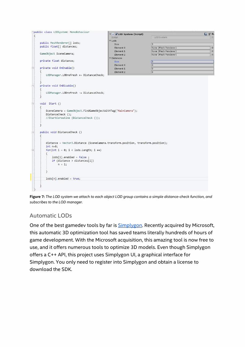
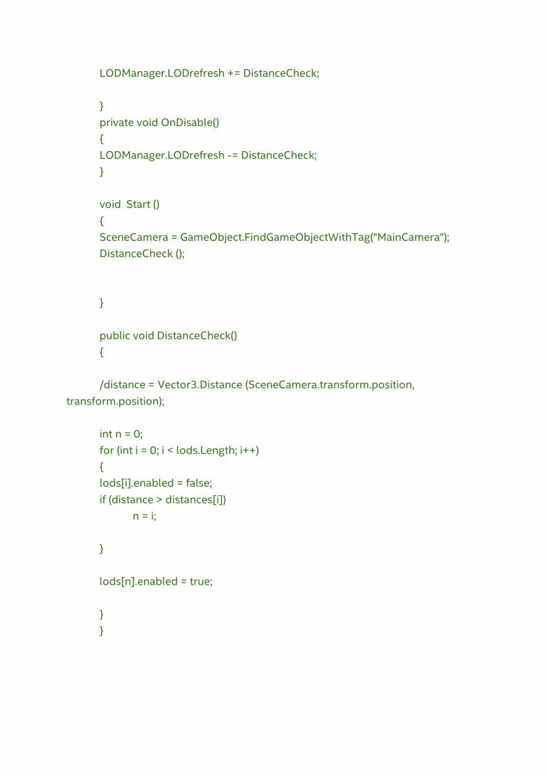
Figure 7: The LOD system we attach to each object LOD group contains a simple distance-check function, and subscribes to the LOD manager.
Automatic LODs
One of the best gamedev tools by far is Simplygon. Recently acquired by Microsoft, this automatic 3D optimization tool has saved teams literally hundreds of hours of game development. With the Microsoft acquisition, this amazing tool is now free to use, and it offers numerous tools to optimize 3D models. Even though Simplygon offers a C++ API, this project uses Simplygon UI, a graphical interface for Simplygon. You only need to register into Simplygon and obtain a license to download the SDK.

Figure 8: The Simplygon* download page. From the Simplygon UI, choose Local. (The grid option is to use a centralized server for Simplygon clients.) The interface is easy to use; dragging and dropping a model into the scene view will load it. Use the tools in the right panel to process different LODs.
Figure 9: Simplygon* user interface has options for different LOD profiles and optimization tools.
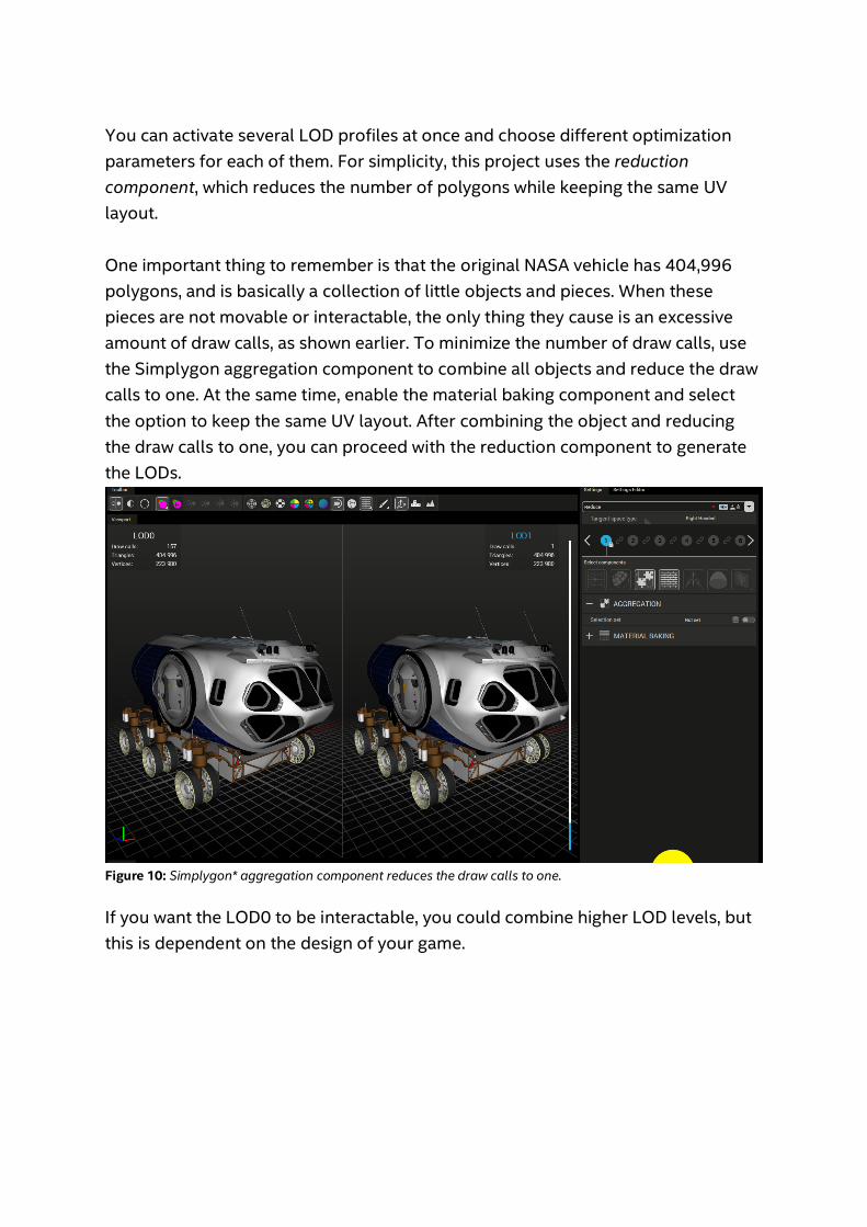
You can activate several LOD profiles at once and choose different optimization parameters for each of them. For simplicity, this project uses the reduction component, which reduces the number of polygons while keeping the same UV layout. One important thing to remember is that the original NASA vehicle has 404,996 polygons, and is basically a collection of little objects and pieces. When these pieces are not movable or interactable, the only thing they cause is an excessive amount of draw calls, as shown earlier. To minimize the number of draw calls, use the Simplygon aggregation component to combine all objects and reduce the draw calls to one. At the same time, enable the material baking component and select the option to keep the same UV layout. After combining the object and reducing the draw calls to one, you can proceed with the reduction component to generate the LODs.
Figure 10: Simplygon* aggregation component reduces the draw calls to one.
If you want the LOD0 to be interactable, you could combine higher LOD levels, but this is dependent on the design of your game.
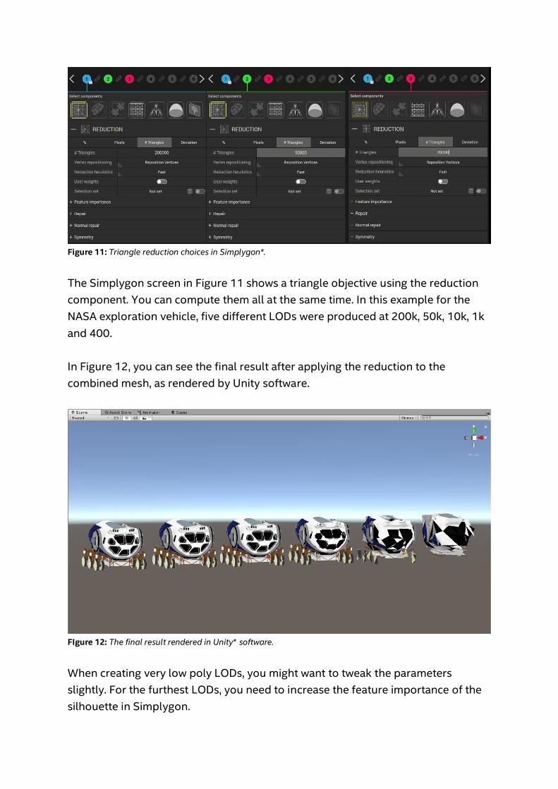
Figure 11: Triangle reduction choices in Simplygon*. The Simplygon screen in Figure 11 shows a triangle objective using the reduction component. You can compute them all at the same time. In this example for the NASA exploration vehicle, five different LODs were produced at 200k, 50k, 10k, 1k and 400. In Figure 12, you can see the final result after applying the reduction to the combined mesh, as rendered by Unity software.
FIgure 12: The final result rendered in Unity* software. When creating very low poly LODs, you might want to tweak the parameters slightly. For the furthest LODs, you need to increase the feature importance of the silhouette in Simplygon.
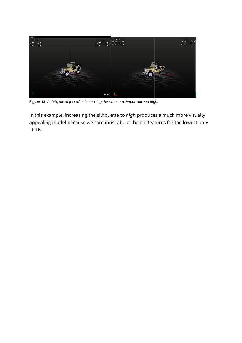
Figure 13: At left, the object after increasing the silhouette importance to high. In this example, increasing the silhouette to high produces a much more visually appealing model because we care most about the big features for the lowest poly LODs.

Figure 14: Silhouette set to high. To see what using these LODs together with the LOD system script achieves in terms of performance, a real-time light is used to discern the actual performance gain. You need to create a prefab with the different LOD levels inside, and then choose some parameters for the LOD system according to your level and design.
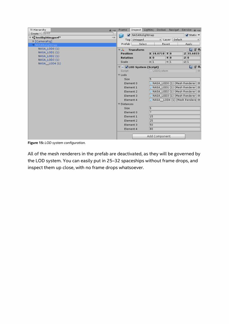
Figure 15: LOD system configuration.
All of the mesh renderers in the prefab are deactivated, as they will be governed by the LOD system. You can easily put in 25–32 spaceships without frame drops, and inspect them up close, with no frame drops whatsoever.
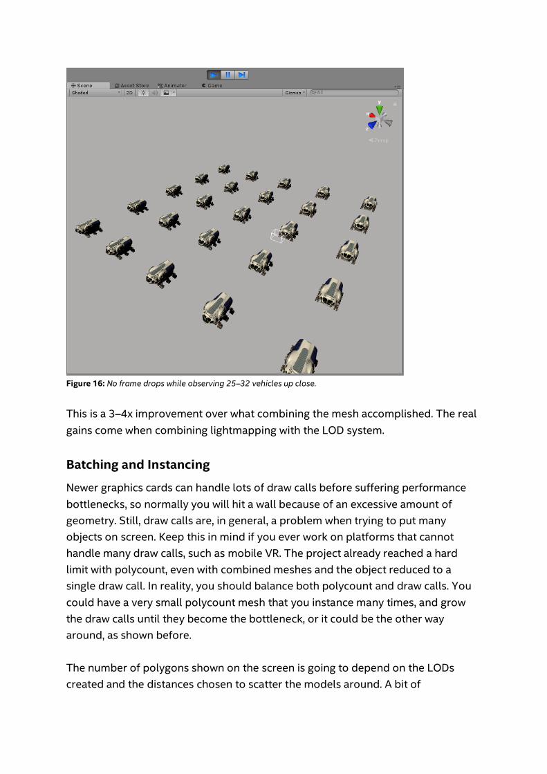
Figure 16: No frame drops while observing 25–32 vehicles up close. This is a 3–4x improvement over what combining the mesh accomplished. The real gains come when combining lightmapping with the LOD system.
Batching and Instancing
Newer graphics cards can handle lots of draw calls before suffering performance bottlenecks, so normally you will hit a wall because of an excessive amount of geometry. Still, draw calls are, in general, a problem when trying to put many objects on screen. Keep this in mind if you ever work on platforms that cannot handle many draw calls, such as mobile VR. The project already reached a hard limit with polycount, even with combined meshes and the object reduced to a single draw call. In reality, you should balance both polycount and draw calls. You could have a very small polycount mesh that you instance many times, and grow the draw calls until they become the bottleneck, or it could be the other way around, as shown before. The number of polygons shown on the screen is going to depend on the LODs created and the distances chosen to scatter the models around. A bit of
experimentation is required, and each game is different; but if you want to be a bit more aggressive with the polygon count, you need to reduce the amount of draw calls. Batching is a technique for combining draw calls before sending them to the GPU. This is done by combining mesh information in the CPU in batches. Unity software has three types of batching (combining) methods to reduce the number of draw calls in a scene:
1. Static batching, which combines meshes of static objects in large meshes at build time, and at run time renders them as one batch per mesh.
2. Dynamic batching finds small meshes and batches them into fewer draw calls.
3. GPU instancing is not exactly batching, as it is done entirely in the GPU. This technique draws identical meshes, but with different attributes such as transforms. You can tweak it to add per-instance data such as colors and transforms in the GPU, so that the CPU sends the mesh data once, and sends the per-instance data per instance.
Static Batching Static batching only works with static meshes marked as such before run time. The engine calculates their contribution, combines meshes, and reduces draw calls of similar objects. You need to consider several things when trying to get this type of batching to work. For example, you need to use the same materials, and there are some situations in which it might not be favorable. For more information, see Draw call batching in the Unity documentation. Static batching will be of no use because you want to instantiate these objects at run time.
Dynamic Batching Dynamic batching works at run time, but it has several restrictions. Still, it might work with the models in this project.

Figure 17: Batching efficiency analysis inside Unity* software.
Dynamic batching doesn’t seem to work in this case. The Unity Frame Debugger is a great tool—akin to Intel GPA but specific to the engine—that can help you pinpoint the reason batching doesn’t work. In the debugger, you can analyze each of the draw calls made for rendering a specific frame.
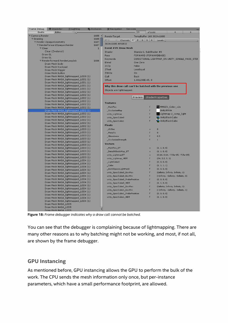
Figure 18: Frame debugger indicates why a draw call cannot be batched. You can see that the debugger is complaining because of lightmapping. There are many other reasons as to why batching might not be working, and most, if not all, are shown by the frame debugger.
GPU Instancing As mentioned before, GPU instancing allows the GPU to perform the bulk of the work. The CPU sends the mesh information only once, but per-instance parameters, which have a small performance footprint, are allowed.

In Unity software, this is achieved by marking the object as GPU-instanced in its material. You can only apply this to objects that share the same mesh and material. By default, the only per-instance data in Unity Standard Shader is the transform. You can create shaders of your own to add other variations. This project uses the Standard Shader with GPU Instancing enabled.
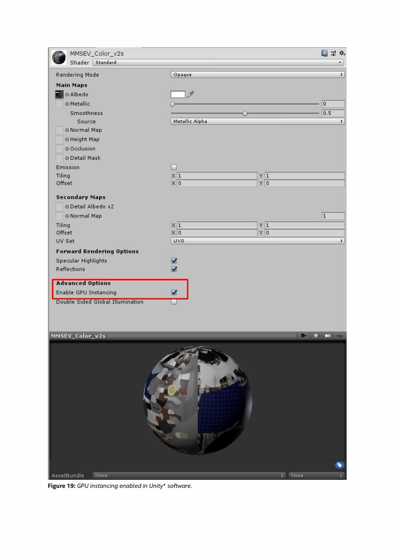
Figure 19: GPU instancing enabled in Unity* software.
For an explanation of GPU instancing, see Unity software documentation on GPU instancing.
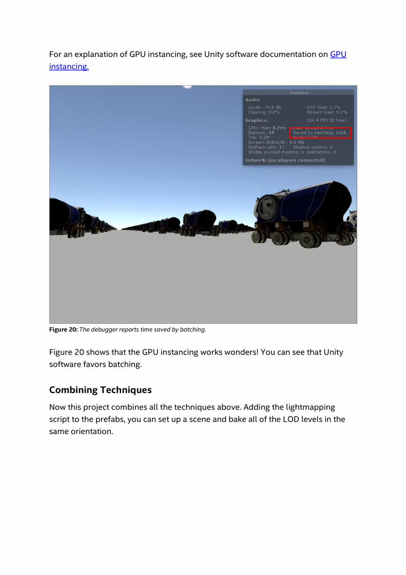
Figure 20: The debugger reports time saved by batching. Figure 20 shows that the GPU instancing works wonders! You can see that Unity software favors batching.
Combining Techniques
Now this project combines all the techniques above. Adding the lightmapping script to the prefabs, you can set up a scene and bake all of the LOD levels in the same orientation.
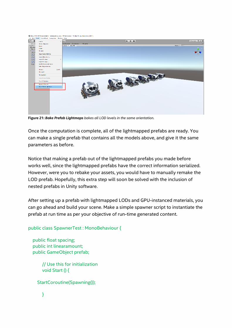
Figure 21: Bake Prefab Lightmaps bakes all LOD levels in the same orientation. Once the computation is complete, all of the lightmapped prefabs are ready. You can make a single prefab that contains all the models above, and give it the same parameters as before. Notice that making a prefab out of the lightmapped prefabs you made before works well, since the lightmapped prefabs have the correct information serialized. However, were you to rebake your assets, you would have to manually remake the LOD prefab. Hopefully, this extra step will soon be solved with the inclusion of nested prefabs in Unity software. After setting up a prefab with lightmapped LODs and GPU-instanced materials, you can go ahead and build your scene. Make a simple spawner script to instantiate the prefab at run time as per your objective of run-time generated content. public class SpawnerTest : MonoBehaviour { public float spacing; public int linearamount; public GameObject prefab; // Use this for initialization void Start () { StartCoroutine(Spawning()); }
public IEnumerator Spawning() { for (int i = 0; i < linearamount; i++) { for (int j = 0; j < linearamount; j++) { GameObject p = Instantiate(prefab, new Vector3((float)i * spacing, 0f, (float)j * spacing), prefab.transform.rotation) as GameObject; } yield return null; } } } Play with the distance of instantiating the object to keep the polycount on screen to a value that Unity software can display. The result is really impressive. You can easily instantiate more than 10,000 spaceships with no frame drop whatsoever, and no LOD switching visible to the player. But why get stuck with about 10,000 ships? The techniques applied in this project do limit the number of polygons shown on the screen. In principle, you could expect the number of objects to be much larger; as big as you wanted, theoretically, since the total polygon output using our techniques is limited. As a matter of fact, it can be, but with a bunch of minor script optimizations. The bottleneck in this case, believe or not, is in the LOD system. The way it’s programmed, although clear and straightforward, causes huge performance spikes when switching LOD models. Every time the player teleports, thousands of objects are updated, and their distance calculations drag down Unity software’s performance, memory management, and allocation.
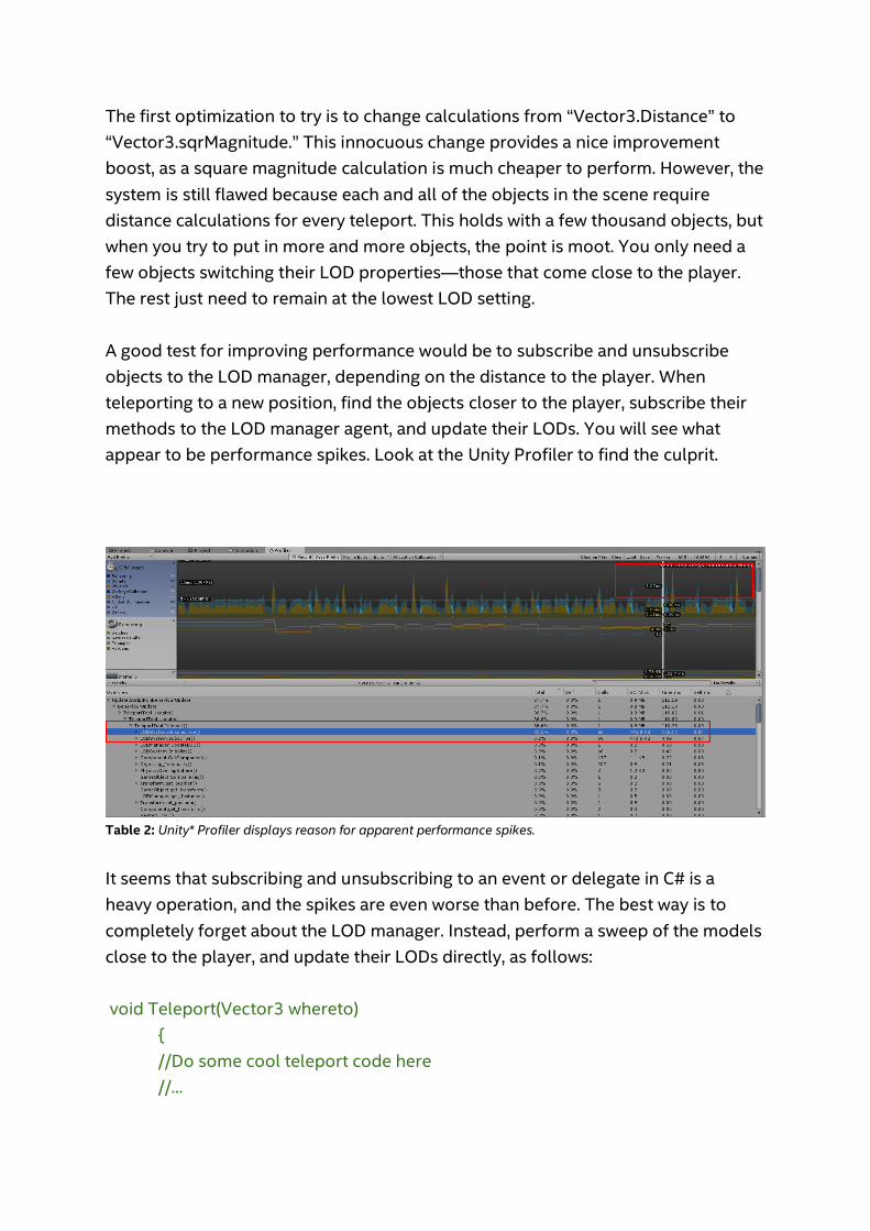
The first optimization to try is to change calculations from “Vector3.Distance” to “Vector3.sqrMagnitude.” This innocuous change provides a nice improvement boost, as a square magnitude calculation is much cheaper to perform. However, the system is still flawed because each and all of the objects in the scene require distance calculations for every teleport. This holds with a few thousand objects, but when you try to put in more and more objects, the point is moot. You only need a few objects switching their LOD properties—those that come close to the player. The rest just need to remain at the lowest LOD setting. A good test for improving performance would be to subscribe and unsubscribe objects to the LOD manager, depending on the distance to the player. When teleporting to a new position, find the objects closer to the player, subscribe their methods to the LOD manager agent, and update their LODs. You will see what appear to be performance spikes. Look at the Unity Profiler to find the culprit.
Table 2: Unity* Profiler displays reason for apparent performance spikes. It seems that subscribing and unsubscribing to an event or delegate in C# is a heavy operation, and the spikes are even worse than before. The best way is to completely forget about the LOD manager. Instead, perform a sweep of the models close to the player, and update their LODs directly, as follows: void Teleport(Vector3 whereto) { //Do some cool teleport code here //...
Collider[] objs = Physics.OverlapSphere(transform.position, 100f); for (int i = 0; i < objs.Length; i++) { LODSystem lod = objs[i].GetComponent<LODSystem>(); if (lod != null) lod.DistanceCheck(); } } Now the system works very well. You can put in more than 250,000 ships and everything seems to be smooth. Now, a gotcha moment: The scene with 250,000 ships works flawlessly for a while, but after you play a bit and teleport all around the map, the performance starts dropping seriously. Basically, when teleporting forward, the LOD system updates the objects around the player after teleporting, leaving a bunch of highly detailed objects behind without updating them. Every time you teleport, many extra, unnecessary high-poly models are left behind. Update the code, changing all objects; the new ones close to the player and those left behind. void Teleport(Vector3 whereto) { //Objects close to the player before teleporting Collider[] objs = Physics.OverlapSphere(transform.position, 100f); //Do some cool teleport code here //... //Objects close to the player after teleporting Collider[] objs2 = Physics.OverlapSphere(transform.position, 100f); for (int i = 0; i < objs.Length; i++)
{ LODSystem lod = objs2[i].GetComponent<LODSystem>(); if (lod != null) lod.DistanceCheck(); } for (int i = 0; i < objs.Length; i++) { LODSystem lod = objs[i].GetComponent<LODSystem>(); if (lod != null) lod.DistanceCheck(); } }
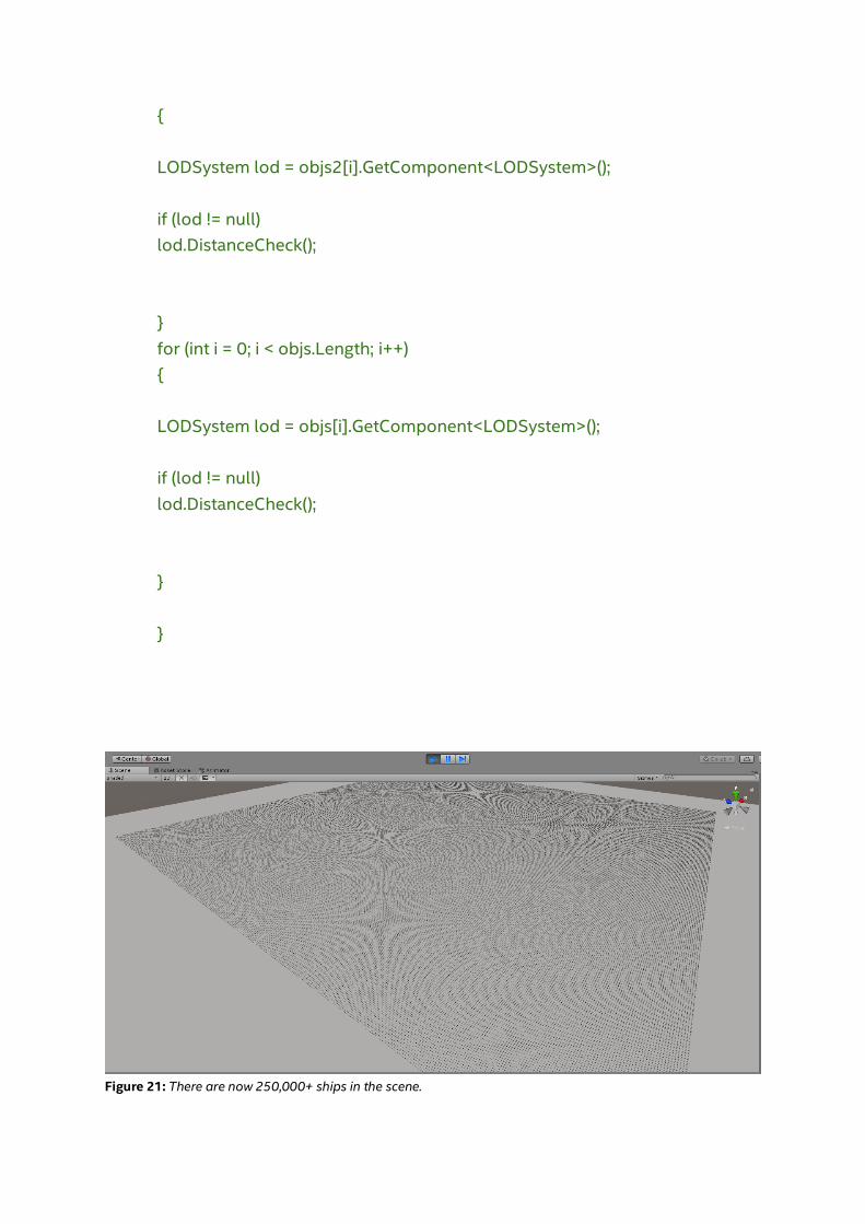
Figure 21: There are now 250,000+ ships in the scene.

Each little dot in Figure 21 is a spaceship, and a scene of more than 250,000 ships is a big improvement over the starting point of three or four spaceships in the scene.
Conclusion
This is obviously an exaggerated example, but these techniques can help you create massive games with many elements. Imagine lush forests and extensive maps, all randomly generated and highly detailed in a VR experience. Use some of these techniques in your own game for impressive results. Notices
No license (express or implied, by estoppel or otherwise) to any intellectual property rights is granted by this document.
Intel disclaims all express and implied warranties, including without limitation, the implied warranties of merchantability, fitness for a particular purpose, and non-infringement, as well as any warranty arising from course of performance, course of dealing, or usage in trade.
This document contains information on products, services and/or processes in development. All information provided here is subject to change without notice. Contact your Intel representative to obtain the latest forecast, schedule, specifications and roadmaps.
The products and services described may contain defects or errors known as errata which may cause deviations from published specifications. Current characterized errata are available on request.
Copies of documents which have an order number and are referenced in this document may be obtained by calling 1-800-548-4725 or by visiting www.intel.com/design/literature.htm.
This sample source code is released under the Intel Sample Source Code License Agreement.
Intel, the Intel logo, and Intel Core are trademarks of Intel Corporation in the U.S. and/or other countries.
Microsoft, Windows, and the Windows logo are trademarks, or registered trademarks of Microsoft Corporation in the United States and/or other countries.
*Other names and brands may be claimed as the property of others.
© 2018 Intel Corporation


![Furion: Engineering High-Quality Immersive Virtual Reality ...gxc27/teach/597/Furion.pdf1 INTRODUCTION The consumer virtual reality (VR) revolution started around 2012 ... Unity [21]](https://static.fdocuments.net/doc/165x107/5f54caa7da8a7a23602b1da5/furion-engineering-high-quality-immersive-virtual-reality-gxc27teach597.jpg)