Optimization and improvement of NSCU 1.0. Universal...
100
Optimization and improvement of NSCU 1.0. Universal Functional Tester produced by Evoleo Technologi SANDRA LUDCZAK Fevereiro de 2016
Transcript of Optimization and improvement of NSCU 1.0. Universal...

Optimization and improvement of NSCU1.0. �Universal Functional Tester producedby Evoleo Technologi
SANDRA LUDCZAKFevereiro de 2016

1
ERASMUS PROJECT
EVOLEO TECHNOLOGIES
Author
SANDRA ŁUDCZAK (1150197)
27.JAN.2016

ERASMUS PROJECT SANDRA ŁUDCZAK
2
Acknowledgements
People collaborating in the presented Erasmus Project are listened below:
Ing. Rodolfo Martins is the owner and main chef of EVOLEO Technologies company in
which the project was carried out. He was the one to acquaint me into the project, showed
main tools for comparing products in the manufacturing process and presented Project
Development Process Theories, such as: System Requirements Review, Product
Development & Analysis, Critical Design Review. Also, his main role in the project was to
monitor the work progress and specify the path of development. Rodolfo Martins was
a great help during fulfilling this project and always was open for new ideas.
Ing. Tiago Silva is team member of the Mechanical Team and also supervisor of this project.
Thanks to him I have learned a lot about the computer-aided engineering software
program Solidworks. Always when doubts or questions have been raised he gave me
a helping hand. Together we discussed upcoming ideas, concepts, work progress etc. From
my observations he was one of the most efficient employees and EVOLEO Technologies
should feel happy to have him.
Ing. Helder Fonseca is one of the General Managers in Evoleo Technologies. He helped me
during the verification of requirements, choosing key drivers for my project and providing
me with helpful books and information when it was necessary.
Ing. Sara Freitas and Ing. Isabel Pinto – Ing. Freitas and Ing. Pinto helped me to understand
the main driver factors I should consider in my project. Together we managed to chose
adequate verification methods and define planned actions. Both ladies had always a smile
on their faces and were open for any help.

ERASMUS PROJECT SANDRA ŁUDCZAK
3
Abstract
The aim of the project was to improve an existing testing machine that is produced
by the company EVOLEO Technologies. New conceptions of each part have been invented
in order to produce an innovative unit that combines optimal segments from the old
construction with the new, improved ones. The machine is meant to be testing different
kind of devices that use specific elements like: buttons, knobs, monitors. The main purpose
is to create various concepts of components that could be changed in order to lower the
cost, weight or to simplify the operating process. Figure 1. shows the already existing
discussed device.
Figure 1. NSCU 1.0. Universal Functional Tester – testing machine produced by Evoleo Technologies.
Keywords
Optimization process, Testing machine, EVOLEO Technologies, Device modelling, Automated
testing.

ERASMUS PROJECT SANDRA ŁUDCZAK
4
List of Contents
Acknowledgements ....................................................................................................... 2
Abstract ........................................................................................................................ 3
List of Contents ............................................................................................................. 4
List of Symbols and Abbreviations ................................................................................ 6
1. Introduction ............................................................................................................... 8
1.1. Company characterization .............................................................................. 8
1.2. The Problem ................................................................................................... 9
1.3. Methods ........................................................................................................ 10
1.4. Methods ........................................................................................................ 11
Requirements analysis ........................................................................................... 12
Reliability – theoretical terms ................................................................................. 12
2. Background ............................................................................................................. 13
2.1.Requirements analysis ..................................................................................... 13
2.1.1. Principals requirements .................................................................. 13
2.1.2. Company requirements .................................................................. 15
2.2. Product Development Process...................................................................... 15
2.3. Reliability – theoretical terms ....................................................................... 18
3. Development ........................................................................................................... 20
3.1. Problem analysis .......................................................................................... 20
3.2. Preliminary drafts .......................................................................................... 20
3.2.1. Upper part concepts ....................................................................... 21
3.2.2. Middle part concepts ...................................................................... 23
3.2.3. Lower part concepts ....................................................................... 26
3.3. Selecting the best idea ................................................................................. 31
3.3.1. Upper part selection ....................................................................... 32
3.3.2. Middle part selection ....................................................................... 35
3.3.3. Lower part selection ....................................................................... 49
3.4. Developing the main idea ............................................................................. 53
3.4.1. Upper part development ................................................................. 53
3.4.2. Middle part development ................................................................ 54
3.4.3. Lower part development ................................................................. 71
3.5. Budgeting ........................................................................................................ 80
3.6. Critical analysis and prospects for improvement .............................................. 82
3.7. Equipment instructions manual ........................................................................ 83

ERASMUS PROJECT SANDRA ŁUDCZAK
5
3.8. Maintenance Guidelines .................................................................................. 83
4. Concluding remarks ........................................................................................... 89
5. Bibliography and others sources of information ....................................................... 92
6. Appendixes ............................................................................................................. 95

ERASMUS PROJECT SANDRA ŁUDCZAK
6
List of Symbols and Abbreviations
Abbreviation Meaning
CDR
CEO
DUT
ECTS
EU
FIT
MTBF
MTTF
MTTR
PDA
SME
SRR
VCD
WCA
Critical Design Review
Chief Executive Officer
Device Under Test
European Credits Transfer System
European Union
Failure In Time
Mean Time Between Failure
Mean Time To Failure
Mean Time To Repair
Product Development & Analysis
Small or Medium Enterprise
System Requirements Review
Verification Control Document
Worst Case Analysis

ERASMUS PROJECT SANDRA ŁUDCZAK
7
1. INTRODUCTION
Company characterization
The problem
Methods used

ERASMUS PROJECT SANDRA ŁUDCZAK
8
1. Introduction
This work was carried out based on an ERASMUS PROJECT in order to receive 30
ECTS points in the academic year 2015/2016. In association with the company EVOLEO
TECHNOLOGIES it was possible to initiate a project under the name: “Optimization and
improvement of NSCU 1.0. Universal Functional Tester produced by EVOLEO
Technologies”. In this project the main goal was to optimize the already existing Universal
Functional Tester Machine.
1.1. Company characterization
EVOLEO Technologies is a Portuguese SME investing in skills related to the design of
critical and highly complex electronic systems. EVOLEO embraces five areas of activity:
Space, Transportation, Energy, Health and Industry. Its mission is to provide high-end and
differentiated electronic engineering solutions, seeking continuous improvement,
flexibility, quality and customer oriented innovation. Its main partners are: Efacec, ESA,
EMEF. One of their clients is even BOSCH company. EVOLEO Technologies searches and
promotes partnerships and networking with centres of knowledge and industry players in
line with its mission of providing high-end and differentiated electronic engineering
solutions, seeking continuous improvement, flexibility, quality and customer oriented
innovation [1]. EVOLEO Technologies is located in Rua Gonçalo Mendes da Maia
1350–1H, Pedrouços, Maia in Portugal. The work group is created by 20 people, in which
there is one main chef, the CEO (Chief Executive Officer), one Deputy CEO, four General
managers and 14 engineers working in 7 different classified groups. The organisation chart
is shown in Figure 2. The CEO, Deputy - CEO and the General Managers create an own
group called Technical Management Team.
Currently the company is leading six projects: TDP8, GaNSAT, SEAS, NewP@ss, PEDDIR and
CARCODE. For more information it is recommended to visit the website
http://evoleotech.com/company/projects/ .

ERASMUS PROJECT SANDRA ŁUDCZAK
9
Figure 2. EVOLEO Technologies organisation chart.
1.2. The Problem
In September 2015 EVOLEO Technologies has released the first model of an Universal
Functional Tester Machine which main purpose was to test components of
a specific device, shown in Figure 3. It is a device produced by BOSCH company. The units
that needed to be tested were: the buttons, knob and display. The problem with the
prototype machine was that it was customized just to accommodate one specific device (or
one with similar dimensions to the ones shown in Figure 3). The need to improve the
Universal Functional Tester occurs. It needed to be able to test different – shaped products
as well as measure in angles. First, the whole machine was divided into 3 parts, called in
this project: Upper part – responsible for horizontal movement of the testing ending,
Middle part – responsible for its vertical movement and Lower part – being the placement
of product unit with adequate needle pad. Every single stage of the project is mentioned
below.

ERASMUS PROJECT SANDRA ŁUDCZAK
10
Figure 3. BOSCH product – to be tested.
1.3. Methods used
In order to solve the received task it was necessary to do some researches of already
existing solutions in the internet, get knowledge from people working at the company who
are more experienced in the topic, as well as undergo brain storming1 sessions with friends
and colleagues. Very helpful was also reaching for literature such as: Dietrich M., Podstawy
Konstrukcji Maszyn, Tom 1, Wydawnictwo Naukowo – Techniczne, Tom I, Tom II, 1999,
Niezgodziński Michał E., Niezgodziński T., Wytrzymalość materiałów PWN, Warszawa,
2002. The first stage of the project was to come up with own solutions not to be inspired
by any already existing concepts. At this point the main goal of the final project was given
(without any details) and imaginary solutions were created. Later, the previous Machine
was presented (in order to receive more detailed information) and the old version was
optimised. The last step was to create completely new and innovative parts, that needed
to be cheap and very reliable. Additionally, in order to evaluate the invented concepts they
were designed in the computer-aided engineering software SolidWorks.
1 Process for generating creative ideas and solutions through intensive and freewheeling group discussion.
Every participant is encouraged to think aloud and suggest as many ideas as possible, no matter seemingly how
outlandish or bizarre. Analysis, discussion, or criticism of the aired ideas is allowed only when the brainstorming
session is over and evaluation session begins.

ERASMUS PROJECT ` SANDRA ŁUDCZAK
11
1.4. Methods
A GANTT chart has been created in order to organize the work and track the achieved results in time. The red fields point out the ‘milestones’
executed in each phase. It is presented in the Figure 4.
Figure 4. GANTT chart of the project.

ERASMUS PROJECT SANDRA ŁUDCZAK
12
BACKGROUND
Requirements analysis
Product Development Process
Reliability – theoretical terms

ERASMUS PROJECT SANDRA ŁUDCZAK
13
2. Background
2.1. Requirements analysis
The first step in designing the Universal Functional Tester was to establish
requirements, which the machine needs to fulfil. These mechanical requirements have been
divided into two categories – one that have been given by BOSCH company, the other one that
have been established by EVOLEO company, during the designing process.
2.1.1. Principal requirements
The company which commissioned the order to test their specified product (Figure 5)
came up with special mechanical requirements that should be considered while designing the
device. Additionally, the firm emphasized that they are planning to produce a new product in
the near future. Its size will be much bigger so the testing machine should be able to
accommodate different kinds of products that are needed to be tested. The main conditions
are listened underneath. The whole list can be found in the Appendixes Chapter (Attachement
1).
Figure 5. BOSCH product – to be tested.
The platform shall have a vision system with controlled lighting (darkroom)
The platform should have a pressure system allowing the mechanical performance of
testing the buttons of the product (linear - controller => XY coordination, actuator
rotatable with suction (vacuum) to allow the rotation of knob)

ERASMUS PROJECT SANDRA ŁUDCZAK
14
The vision and pinch systems should be programmable in space (x, y) whenever
necessary test another type of product
Exchange of the movable table, on which the product is placed should be done quickly,
not slower than 1 min
The platform should be provided with an interconnection system between measuring
equipment and the test fixture
The connection interface systems should support at least:
2 x RJ45 Cat5e FTP;
2 X USB 2.0
Pneumatic -2 x (4mm w / check valve)
20 X coaxial lines (10x 50 Ohm + 10x 75 Ohm)
60 X signal lines;
20 X lines to 230V / 5A
The platform must be prepared to receive fixture / jig with dimensions enabling the
product testing dimensions up to (400 mm x 300 mm x 100 mm)
The platform must have a 19" rack with a minimum capacity of 12 V
The platform should be movable
The Test fixture should be compatible with the platform
The Test fixture should have a base capable of placing the product
The test fixture should have a bed of needles (behind) helping to relate the connection
points of the product with the machine
The maximum size of the JIG and / or equipment for placing the product is
80 mm x 90 mm x 110mm
The platform should respect the BOSCH Standard N62A
The JIG should allow product updates => exchanging of tested element

ERASMUS PROJECT SANDRA ŁUDCZAK
15
The maximum weight of the JIG and / or equipment for placing the product must be
limited to a maximum of 100 N
If the cassettes weight is more than 100 N (up to 180 N) it has to be supported by
another construction
2.1.2. Company requirements
A large list of requirements has been created (Attachement 1). In order to evaluate
the different concept ideas in terms of these requirements, they needed to be divided
into smaller factors which are listened in Table 1.
Table 1. Key drivers of the project.
Reliability
Maintainability
Availability
Safety
Cost
Functionality
Operability
Appearance
2.2. Product Development Process
In order to start the problem solving of this project it was essential to gain
knowledge about the different phases each project requires during its manufacturing
process. In theory each product development process is defined by six main phases. Each
phase is listened and explained below.

ERASMUS PROJECT SANDRA ŁUDCZAK
16
Product Development Process [2] – it is a system of defined steps and tasks (e.g. strategy,
organization, concept generation, marketing plan creation, evaluation, and
commercialization) of a new product. During that cycle companies establish ideas to follow
in order to reach a visible goal at a certain period of time. The different phases of the
Product Development Process are following:
A. Conceptual phase [3] – in this phase of project planning the attention is focused on
producing ideas and analysing its advantages and disadvantages. The main goal of this
phase is to minimize the likelihood of error, manage costs, assess risks, and evaluate the
potential success of the intended project.
The conceptual phase in this project was divided into another two phases:
A0. User requirements – It was focused on analyzing and evaluating the
requirements given by the principal company (in the case of this project –
BOSCH company). Most important key drivers have been chosen, requirements
have undergone some changes and future actions considering chosen factors
have been planned. Very helpful in this stage was the SRR.
SSR (System Requirements Review) – It is a review aimed to ensure that system
requirements have been completely and properly identified and that a clear
understanding between the principal and the mandatory exists.
A1. Concepts & System Requirements – in this phase the first concepts have been
created, their SWOT analysis have been made and comparisons were
undergone.
SWOT analysis – As the letters suggest SWOT is the meaning of Strengths,
Weaknesses, Opportunities and Threads of the manufactured, new product
concept. Each concept was evaluated by usage of that method. Later, the
outcome of has been compared and the best solution has been chosen.
B. PDA (Preliminary Design Analysis) phase – In this stage of the project the different
interfaces and subsystems are being defined in order to be aware of all equipment that
needs to be considered when producing the given object. A very useful thing is to withdraw
connections between the different subsystems and define their sublevels (up to precisely

ERASMUS PROJECT SANDRA ŁUDCZAK
17
designate their specification). One of the most important analysis that need to be
evaluated at this time is the Worst Case Analysis (WCA). Previous material choices are
being made.
WCA (Worst Case Analysis) [4] – It is a very important step during
manufacturing process. The WCA is meant to detect defects and deficiencies
prior to the production and delivery phase and eliminate them. The WCA usually
includes stress and derating analysis, failure modes and critical effects as well as
reliability prediction. During the WCA it needs to be verified if the product is
robust enough to provide operation which meets the system performance
specification.
C. Detailed design phase – During the detailed design the manufactured product is
being fully defined wherein each subsystem is fully specified. Update of requirements list is
highly required. At this stage the Critical Designed Review (CDR) is utilized. Also, some CAD
models of the given concept are being made which give valuable information about the
three dimensional movement possibilities of the designed product.
CDR (Critical Designed Review) – A strict review over the Verification Control
Document is undertaken in which it is determined if the detailed design is
satisfying. Eventual changes are being implemented.
D. Testing & Verification phase – During that phase the final concept is being
produced. A lot of tests need to be undergone in order to verify the robustness, reliability,
functionality etc. Of the manufactured unit. If any deviations from desired norms are being
observed one more time the VCD needs to be overviewed and eventually changed.
E. Validation phase – this phase is usually realized together with the principal and the
mandatory. The main goal is to prove if the system does exactly what it was built for. One
more time it needs to be tested if the machine fulfills all established requirements. It is the
last time to amend any changes if necessary.

ERASMUS PROJECT SANDRA ŁUDCZAK
18
2.3. Reliability – theoretical terms
In order to come up with innovative solutions that will be reliable valuable
knowledge about the below mentioned terms must have been adopted.
Mean Time Between Failure (MTBF) is a reliability term used to provide the amount of
failures per million hours for a product. This is the most common inquiry about a product’s
life span, and is important in the decision-making process of the end user [1].
Mean Time To Repair (MTTR) is the time needed to repair a failed module [1].
Mean Time To Failure (MTTF) is a basic measure of reliability for non-repairable systems. It
is the mean time expected until the first failure of a piece of equipment. MTTF is
a statistical value and is meant to be the mean over a long period of time and a large
number of units. Technically, MTBF should be used only in reference to a repairable item,
while MTTF should be used for non-repairable items. However, MTBF is commonly used
for both repairable and non-repairable items [1].
Failure In Time (FIT) is another way of reporting MTBF. FIT reports the number of expected
failures per one billion hours of operation for a device. This term is used particularly by the
semiconductor industry but is also used by component manufacturers. FIT can be
quantified in a number of ways: 1000 devices for 1 million hours or 1 million devices for
1000 hours each, and other combinations. FIT and CL (Confidence Limits) are often
provided together [1].
[1]

ERASMUS PROJECT SANDRA ŁUDCZAK
19
3. DEVELOPMENT
Problem Analysis
Brainstorming and Preliminary drafts
Selecting the best idea
Developing the main idea
Budgeting
Critical Analysis and Prospects of Development
Equipment Instruction Manual
Maintenance Guidelines

ERASMUS PROJECT SANDRA ŁUDCZAK
20
3. Development
In this section, the product manufacturing development is carried out and presented.
It is divided into sub – sections in order to distinguish consecutive steps of the work
progress.
3.1. Problem analysis
The problem presented in chapter 1.2. needed to be solved. The already existing
Testing Machine produced by EVOLEO Technologies needed some very important changes
to be made. Firstly, it was to be guaranteed that the future (second edition) device will be
able to accommodate products provided with different shapes and sizes, not just one (see
Figure 3). That need came up because of future cooperation with BOSCH company, which
was seeking the discussed need for testing their new, innovative products. Secondly, the
NSCU 1.0. (that is the name given by EVOLEO Technologies for the prototype of the
Universal Functional Tester), was not able to test the different devices in angles. If a new
product with non – flat areas would be needed to be tested it would not be possible in the
old version, which was using only linear actuators. Another problem was being faced – the
machine needs to measure in angles. These two mentioned aspects were the main and
most important goals of this project. If it would be possible to solve them while improving
the cost aspects, appearance, innovation etc. It would be a great advantage.
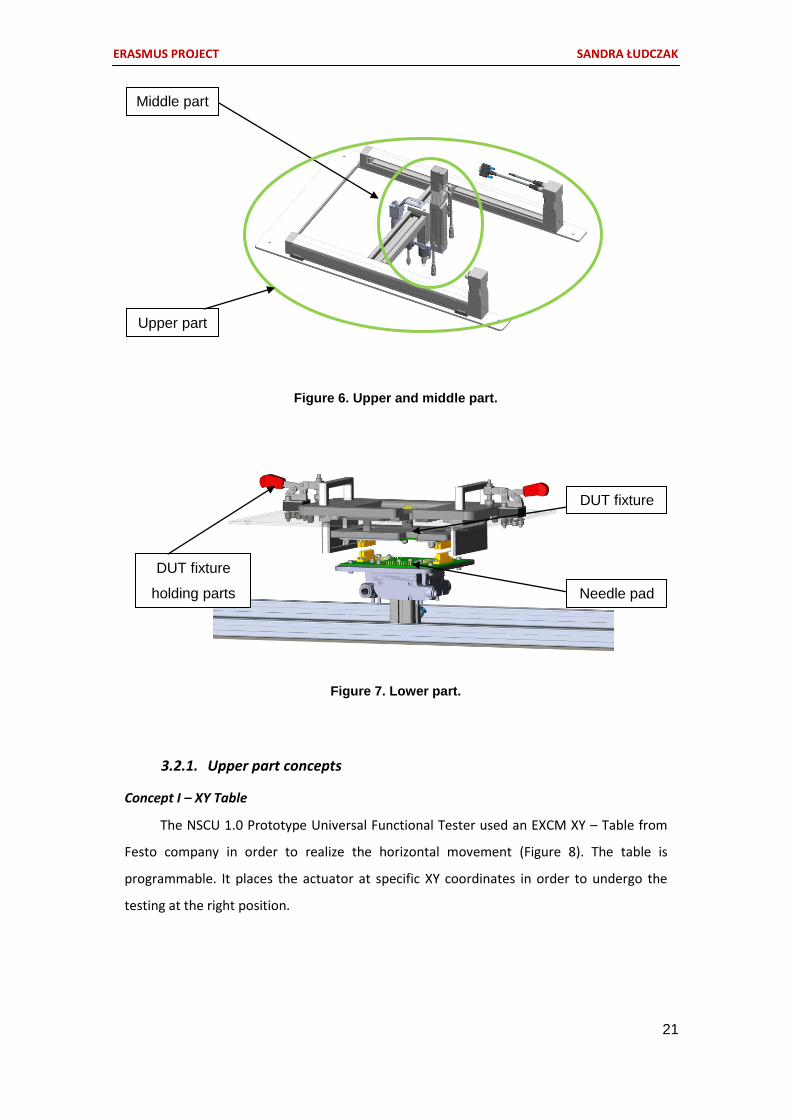
3.2. Preliminary drafts
The NSCU 2.0 Testing Machine was split into 3 parts. So called ‘upper part’
representing movement in the XY axis, ‘middle part’ realizing the vertical movement and
being the actual testing device (with testing endings) and ‘lower part’ being the fixture of
the tested product together with the needle pad. In order to visualise which parts of the
Universal Functional Tester are meant the old version with mentioned parting is being
shown in Figure 6 and Figure 7. These section was divided into three parts, concerning
preliminary concepts of each part.
ERASMUS PROJECT SANDRA ŁUDCZAK
21
Figure 6. Upper and middle part.
Figure 7. Lower part.
3.2.1. Upper part concepts
Concept I – XY Table
The NSCU 1.0 Prototype Universal Functional Tester used an EXCM XY – Table from
Festo company in order to realize the horizontal movement (Figure 8). The table is
programmable. It places the actuator at specific XY coordinates in order to undergo the
testing at the right position.
Middle part
Upper part
Needle pad
DUT fixture
DUT fixture
holding parts

ERASMUS PROJECT SANDRA ŁUDCZAK
22
Figure 8. EXCM XY - Table from Festo company.
Concept II – Electrical platform with magnet
The upper part is a surface equipped in wire paths that lead current. Thanks to
a camera attached to the device the coordinates of the desired tested elements are
known. The electricity is lead to the exact XY coordinates. This affects the lower placed
magnet, which is connected with the lower testing part, to move in the right position. In
order to stop the magnet at a desired position the electrical field needs to be switched off
after a certain time. If we know that the delay of the current equals X it is possible to stop
the magnet at the wanted length at t – X, where t is the time without counting the delay.
Figure 9. Electrical platform concept.
Wire paths
leading current
Magnet Middle part

ERASMUS PROJECT SANDRA ŁUDCZAK
23
Concept III – Robotic arm
The rotational movement is realized by a thrust ball
bearing. In order to increase the range of mobility of the part an
electric actuator is used as shown in Figure 10. Due to that part it
is possible to reach the whole desired movement range. Below
the mentioned actuator the middle part with the actual testing
endings is placed. The joint is realized in a way allowing hinge
movement. The system helps in the mobility incensement.
Figure 10. Robotic arm concept.
3.2.2. Middle part concepts
Two main concepts of the middle part (Figure 11) have been created. The middle
part was the actual unit that needed to be completely improved, that is why the time
focused on this particular device was the longest regarding the whole project. All resulting
ideas are summerized below.
Middle part
Thrust ball bearing
Electric
actuator

ERASMUS PROJECT SANDRA ŁUDCZAK
24
Figure 11. Middle part concepts.
Solution number 2 uses one ball bearing and two servo motors. Possible movements of
the construction are shown in Figure 12. The Z – actuator that is already available to the
company is used for the vertical movement. An servo mechanism is attached to the Z –
actuator, causing rotational movement. In order to relieve the servo motor from axial loads an
additional part is placed onto it, that connects it with a bearing – now the bearing is
responsible for holding the forces. In order to rotate this servo motor, another servo motor is
positioned horizontally to be able to enable lateral movement of the actual testing parts.
1 2

ERASMUS PROJECT SANDRA ŁUDCZAK
25
Figure 12. Servo motor middle part concept.
Solution number 1 (Figure 11;1) uses a ball bearing, one servo motor and one electric
actuator. Possible movements of the construction are shown in Figure 13. The Z – actuator
that is already available to the company is used for the vertical movement. A servo mechanism
is used to cause rotation movement. All axial forces are taken over by the bearing due to an
element that connects it with the part being attached to the servo mechanism. The main
difference between solution 1 and 2 is that solution 1 in order to provide horizontal movement
uses an electric actuator that while moving cause inclination of the testing parts. The
construction is reliable, because the whole mass is placed vertically (no side elements) and also
resistant due to using a stabilizing element and electrical actuator (massive construction).
Ball bearing
resistant
against axial
loads
Rotation
motor
Rotation
motor
Z - actuator
Testing endings

ERASMUS PROJECT SANDRA ŁUDCZAK
26
Figure 13. Electric actuator middle part solution - possible movements.
3.2.3. Lower part concepts
The lower part consists of the upper – product holding DUT fixture and the bottom –
needle pad holding. Two concepts are shown in Figure 14 (1 – the new, innovative one, 2 – the
one used in the previous NSCU 1.0. Universal Functional Tester).
Figure 14. Concepts of Lower part.
Rotation
motor
Electric
actuator
Ball bearing
resistant
against
axial loads
Z - actuator
1 2

ERASMUS PROJECT SANDRA ŁUDCZAK
27
Figure 15. Lower part concept.
Figure 16. Explanaition of the lower part solution.
Solution number 1 uses expansion springs which hold the needle pad apart from the
element responsible for placing the tested product. When the whole testing process begins the
Spring
mounted onto
the shaft in
order to desist
bending.
Holding arms
(attached to
both parts).
Two parts at
equal length
on both sides.
Part to place
the product.
Needle pad
Upper and
Lower part
being
connected.
Holes
prepared
for the
needles
placed
onto the
needle
pad.

ERASMUS PROJECT SANDRA ŁUDCZAK
28
upper part being placed onto the product (for reducing the movement almost to zero) pushes
the upper element onto the needle pad – and so connects the needles with their destination.
Additionally, the upper part is provided in holes corresponding to the places where the several
needles are placed. No complicated mechanisms must be applied and the usage of an electric
actuator raising the needle pad is redundant. The construction can be exchanged fast because
of a holding element attached to both parts. That is a huge advantage.
Solution number 2 which is already used by EVOLEO Technologies uses an electric actuator
which raises the needle pad in order to connect with the product. The construction can be also
exchanged fast because of a holding element attached to both parts.
Concepts of holding part of the placed product in the DUT fixture have been made. The
results are shown below.
Concept I – Spring holdings
The product is placed in the centre of the table. Two holding platforms on the side,
equipped in springs are pushing against the product preventing its movement. On the other
two sides there are tapes that stop the movement of the other two edges. Special clips are
used to hold the platforms while placing the product which then are released in order to hold
the sample.
Figure 17. Spring holding concept.
Concept II – Tape
The product is adhered to a rough surface. A tape is fixed on its corner and is being
loosen or tighten depending on desire to rigidly place the product or exchange it.

ERASMUS PROJECT SANDRA ŁUDCZAK
29
Figure 18. Tape table.
Concept III – Corner holdings
On two opposite corners are holding blocks that are connected with tapes. These tapes
are rolled up on special blocks that automatically release (while exchanging the product) or
strengthen (while holding it still). To consider: The blocks used to manipulate the tape could be
placed on both sides – a possibility of constant releasing and strengthening of tape would
provided.
Figure 19. Corner holdings.
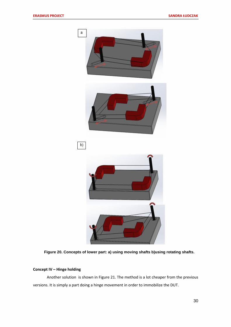
The element that is responsible for holding the product to be tested is presented in
Figure 20. Drawing a) shows a solution using a shaft that while moving horizontally cause
displacement of the blocks due to a tape that is (depending on the wanted result) tensioned or
loosened. A similar solution is shown in Figure b) where the difference lies in the shafts, which
in this example rotate, causing the winding and unrolling of the tape => resulting as well with
displacement of the blocks.
Tested
product
Rough surface Rotational
shaft
ERASMUS PROJECT SANDRA ŁUDCZAK
30
Figure 20. Concepts of lower part: a) using moving shafts b)using rotating shafts.
Concept IV – Hinge holding
Another solution is shown in Figure 21. The method is a lot cheaper from the previous
versions. It is simply a part doing a hinge movement in order to immobilize the DUT.

ERASMUS PROJECT SANDRA ŁUDCZAK
31
Figure 21. Hinge holding.
In order to test the desired device its back part has to be removed. This is because
there has to be a connection with the electric elements inside. After this operation a table
equipped in needles and other indispensable units is raised. Now the electrical devices can
signal if each part is working correctly.
The product is placed in a pin plug, that exactly corresponds to the backside of the
device to be tested. A ‘click’ sound is the sign for the user that the product is correctly placed.
Figure 22. Connection of DUT fixture and needle pad.
3.3. Selecting the best idea
This Chapter is dedicated to all analysis regarding the constructions preliminary designs.
Besides SWOT analysis’ there have also been made comparisons based on the main key drivers
chosen. Table 2 shows the factors that were taking into concern, together with their validation
values and explanation of each single driver.
Hinge movement DUT placement
Product
Needle pad

ERASMUS PROJECT SANDRA ŁUDCZAK
32
Table 2. Requirements and verification values list.
Driver Things to consider Verification
value
Reliability
- Does the components last long, without failure (at least two years)?
10
- Will the construction carry the weight of all components? Is it necessary to use an additional support?
- Will the construction be stable in every case?
- Is it necessary to take great care over the construction (does it need a weekly/monthly etc. service)?
- Will a problem occur during restarting machine if it is not used for a longer time?
Safety
- Is the machine capable of causing harm to the user?
9 - Does the machine stop movement automatically in case of
emergency?
- Does the machine fulfill all needed safety standards?
Maintainability
- Can the parts be easily exchanged by the user?
8 - Is there a component that needs to be exchanged after a certain period of time?
Operability
- Is the machine to be easy operated by the user?
7
- Does the machine need an engineer to use it/ Does someone involved in the project needs to supervise?
- Is it easy to move the machine? Is it movable?
- Do you have to use strength to move it?
- Time needed to change configurations.
Availability - How long can the machine work in a row? 6
Cost - How high are the costs in comparison to the previous used
devices? 5
Innovation/ Appearance/
Design
- Does the appearance encourage the client to buy the product?
4 - How is it different from the others being on the market?
- What makes it unique and reliable at the same time?
Functionality
- Does the device comply with the posed requirements?
3 - Does the individual parts work well together?
3.3.1. Upper part selection
A SWOT analysis has been undergone in order to choose the best concept. For
appointing a winner solution points have been distributed. A positive aspect equals +1 point,

ERASMUS PROJECT SANDRA ŁUDCZAK
33
a negative one -1 point. The concept which gains the highest score automatically wins. Table
3 shows the comparison.
Table 3. Upper part SWOT analysis.
SWOT
XY – Table Magnetic platform R obotic arm
STRENGTHS
Already used/tested solution
Innovative solution Less space needed for
equipment
High reliability factor (practical verification)
Fast working
Realises horizontal and vertical movement at
one time
High maintainability factor (practical
verification)
Construction the most robust
WEAKNESSES
Construction needs much space
Very complicated construction
Higher amount of components - smaller
reliability factor
Inaccurate positioning (zero point calibration
needed)
Need of a large amount of components (including
electrical devices)
More partial movements
needed for accurate positioning
Current delay causing trouble in positioning
Magnets resistance and size of interaction field
OPPORTUNITIES -
New invention on the market -> opportunities
for the company to evolve
Universal part
THREADS -
More time – consuming, need of gathering
professional knowledge about the dependence of
electric and magnetic field
Positioning could be time consuming
+ 4 3 3
- 2 5 3
SUM 2 -2 0

ERASMUS PROJECT SANDRA ŁUDCZAK
34
The winning construction is the XY – Table. It is an already tested and satisfying
solution. Although it had similar points in the STRENGTH section, the two remaining parts
had too many disadvantages that would appear while choosing them.
As the XY – Table turned out to be the best solution, another analysis regarding the chosen key
drivers (see Chapter 2.1.2.) has been made. The result is shown by a radial diagram (Figure 23).
Table 4. XY – Table analysis regarding key drivers.
Driver Verification + Verification - Verification
value
Reliability
Construction stable in every case, can hold desired weight
- 1
Long lasting without failure
Consrtuction doesn't need regular service
The components will work properly afer a long term of no
usage
Already tested construction
Safety Safety cases are preserved, all
standards are included, an 'safety button' is provided
- 1
Maintainability No parts need to be replaced
after a specified period of time Exchange of parts could be
problematic 0,5
Operability
To be operated easily by user
Problem with calibration of zero point
0,8
No need for supervising during usage
Easy movable construction
Just a short workshop needed to show the usage and
different capabilities of the machine
Availability
- 1
Cost Construction already bought Large cost - already existing
product 0,5
Innovation/ Appearance/
Design Professional appearance - 1
Functionality Supports all of the functional
requirements - 1

ERASMUS PROJECT SANDRA ŁUDCZAK
35
Figure 23. Radial diagram XY – Table analysis.
3.3.2. Middle part selection
Two concepts of this part have been created. In order to evaluate witch concept is
stronger an analysis regarding the requirements (together with their verification values) in
has been made. It is to be mentioned that the solutions presented in 3.2.2. (at this stage)
have undergone little changes as realistic parts have been selected. That is why their
appearance slightly changed (Figure 24).

ERASMUS PROJECT SANDRA ŁUDCZAK
36
Figure 24. Improved concepts of middle part.
Algorithms showing components of each concept have been created. It delivers
knowledge about which devices are related to one another, to predict which parts will stop
working in case of failure of one of the other parts.
Figure 25. Algorithm of NSCU 2.0 Testing Machine – I concept.
1 2

ERASMUS PROJECT SANDRA ŁUDCZAK
37
Figure 26. Algorithm of NSCU 2.0 Testing Machine II concept.
1. Reliability
In order to define the reliability of a construction the below listened definitions need
to be known. Knowing the Probability of Failure per Hour (PFH) (see Chapter 2.3) it is easy
to count the possibility of failure during 2 years. Afterwards this value is being subtracted
from 1 in order to get the reliability value for each component during 2 years (one of the
requirements).
[2]

ERASMUS PROJECT SANDRA ŁUDCZAK
38
Table 5. Reliability table for concept I.
Device PFH Reliability
Electric actuator [ADNE-40-20-LAS-A, Festo] 10–7 0,998
Servo motor [EMMS-AS-40-S-LS-SRB, Festo] 3 x 10⁻⁶ 0,947
Servo motor [LVHV342-01, Parker] 3 x 10⁻⁶ 0,947
Pneumatic actuator [ADN-12-30-A-P-A, Festo] 10–7 0,998
Whole middle part 3 x 10–26 0,898
The constructions reliability is almost 90%. That is a satisfying result.
Table 6. Reliability table for concept II.
Device PFH Reliability
Servo motor [EMMS-AS-40-S-LS-SRB, Festo] 3 x 10⁻⁶ 0,947
Servo motor [EMMS-AS-40-S-LS-SRB, Festo] 3 x 10⁻⁶ 0,947
Servo motor [LVHV342-01, Parker] 3 x 10⁻⁶ 0,947
Pneumatic actuator [ADN-12-30-A-P-A, Festo] 10–7 0,998
Thrust ball bearing [51108U, nskamericas] [14] 3 x 10⁻⁶ 0,947
Whole middle part 3 x 10–26 0,803
The reliability of the second concept is 9,5% less reliable than the first version due to the
amount of components. It is because of the amount of components. The first solution has
5 main components, whilst the second has 6 main parts.
2. Technology
Comparison of pneumatic and electrical actuation systems has been made in order
to choose the best possible concept. Regarding different sources of information the Table
7 was created [5, 6, 7].

ERASMUS PROJECT SANDRA ŁUDCZAK
39
Table 7. Pneumatic and electric actuation comparison.
Electromechanical Design Pneumatic Design
Space Required 1x 3x
Controllability Excellent, Very precise Good
Load Very good Good
Accuracy Excellent Sufficient
Speed Good Excellent
Maintenance Very good Sufficient
Noise Very good Sufficient
Installed Cost Good Very good
Operating Cost Good Very good
Total Cost Good Very good
Environment Excellent Sufficient
Based on Table 7, the electrical actuator is obviously better for the need of the NSCU
2.0 Testing Machine, because it needs to be very accurate. Because of the speed though,
the pneumatic actuator is used for the ending intended for actuating the buttons of the
tested product.
3. Maintainability [13]
In maintainability the most important factors are the Mean Time Between Failure
(MTBF) and Mean Time To Failure (MTTF) and Probability of Failure per Hour (PFH) (see
Chapter 2.3). The important values for both concepts are listened below.
Table 8. Maintainability table for concept I.
Device MTTFd [years] PFH
Electric actuator [ADNE-40-20-LAS-A, Festo] 30 ≤ 10–7 < 10–6
Servo motor [EMMS-AS-40-S-LS-SRB, Festo] 10 ≤3 x 10⁻⁶ < 10–5
Servo motor [LVHV342-01, Parker] 10 ≤3 x 10⁻⁶ < 10–5
Pneumatic actuator [ADN-12-30-A-P-A, Festo] 30 ≤ 10–7 < 10–6

ERASMUS PROJECT SANDRA ŁUDCZAK
40
Table 9. Maintainability requirement Table.
REQ. NR REQ. description Solution
REQ.074
At least 2 years working
without failure.
Construction will work without
failure at least 10 years
Table 10. Maintainability table for concept II.
Device MTTFd
[years]
PFH
Servo motor [EMMS-AS-40-S-LS-SRB, Festo] 10 ≤ 10–7 < 10–6
Servo motor [LVHV342-01, Parker] 10 ≤3 x 10⁻⁶ < 10–5
Servo motor [LVHV342-01, Parker] 10 ≤3 x 10⁻⁶ < 10–5
Pneumatic actuator [ADN-12-30-A-P-A, Festo] 30 ≤ 10–7 < 10–6
Thrust ball bearing [51108U, nskamericas] 42 ≤3 x 10⁻⁶ < 10–5
The Mean Time To Failure for trust ball bearings is to be calculated with the underneath
equation [3]:
[3]
Where:
L10 : Basic rating life
C : Basic dynamic load rating, N {kgf}
P : Equivalent dynamic load, N {kgf}
n : Rotational speed, min-1
For the chosen bearing the figures below are listened:
0 kgf [N]
[N]

ERASMUS PROJECT SANDRA ŁUDCZAK
41
Both constructions should last without failure at least 10 years.
4. Cost
Elements used to create the middle part together with their cost summary are
listened in Table 11 and Table 12.
Table 11. Cost table for concept I.
Device Cost
Z actuator [EGSL-BS-45-100-3P, Festo] 1039, 13 EUR [10] + controllers
Electric actuator [ADNE-40-20-LAS-A, Festo] 101,42 EUR [33]
Servo motor [LVHV342-01, Parker] 256,48 EUR [8]
Servo motor [LVHV342-01, Parker] 256,48 EUR [8]
Pneumatic actuator [ADN-12-30-A-P-A, Festo] 112,75 EUR [11]
Total cost: 1766,26 EUR
Table 12. Cost table for concept II.
Device Cost
Z actuator [EGSL-BS-45-100-3P, Festo] 1039, 13 EUR [10] + controllers
Servo motor [EMMS-AS-40-S-LS-SRB, Festo] 774,36 EUR
Servo motor [LVHV342-01, Parker] 256,48 EUR [8]
Servo motor [LVHV342-01, Parker] 256,48 EUR [8]
Pneumatic actuator [ADN-12-30-A-P-A, Festo] 112,75 EUR [11]
Total cost: 2439,20 EUR

ERASMUS PROJECT SANDRA ŁUDCZAK
42
5. Safety
Table 13. Safety requirement table.
REQ. NR REQ. description Solution
REQ.070
The platform must use a safety PLC
whose software is certified to ISO
13849-1 standard.
Safety ISO 13849-1
standards will be
provided.
In both constructions there are no dangerous components which could potentially
hurt the user.
6. Availability
One of the principal requirements was that the machine needs to work without
failure 365 working days a year, 24 hours per day. Therefore all components should be able
to perform at least , as was calculated in equation 5. An average cycle time
of 5 s is assumed.
[4]
7. Functionality
CONCEPT I
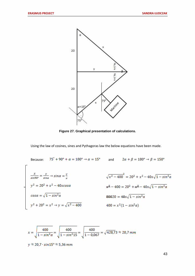
In order to define the range which the construction is able to achieve calculation
have been made. The assumption was that the testing endings should be able to measure
in the angle of at least 150° (75° each side). The arms marked in Figure 27 with the ‘X’ sign
is the surface of the movable table in different positions of the device (max. left and right
inclination).
ERASMUS PROJECT SANDRA ŁUDCZAK
43
Figure 27. Graphical presentation of calculations.
Using the law of cosines, sines and Pythagoras law the below equations have been made.
Because: and

ERASMUS PROJECT SANDRA ŁUDCZAK
44
100 mm
150°
To reach the wanted limit of 150° it is required to have an distance of 5,35 mm
between the hook of the actuator and the fixture of the movable table. Therefore the part
connecting the table with the actuator should be 20,7 mm - 5,36 mm = 15,34 mm.
Figure 28. Angle range of concept I.
The construction allows movement in the
Vertical direction until 100 mm and the swing of
the construction until 75° in each direction.
Figure 29. Vertical range of concept I.

ERASMUS PROJECT SANDRA ŁUDCZAK
45
Figure 30. Angle and horizontal range of concept II.
Figure 31. Range of mobility in vertical direction.
150°
Solution nr 2 has a greater range in
angle than solution nr 1 In Figure 30 the left
drawing shows the side look of the part and
possible angles of testing endings whilst the
right visualises the range of mobility from
above. Figure 31 shows the vertical movement.
100 mm
150 mm

ERASMUS PROJECT SANDRA ŁUDCZAK
46
Table 14. Comparison of concepts.
Driver
CONCEPT II
CONCEPT I
Explanation
Reliability *** **** Concept II has less components that's why it is more reliable.
Safety *** *** Both constructions are fulfil the safety requirements.
Maintainability *** **** Both constructions can work at least 10 years without failure, but considering the
number of components it could be more difficult to maintain concept nr I.
Availability ** ** Working 24h/7days a week for 2 years.
Cost ** *** Concept II cheaper because of usage of electric actuator instead of servo motor.
Additional, concept I needs a thrust ball bearing.
Innovation **** ** Concept II is shorter than concept I which gives more space for placing the product.
Functionality **** ** Concept I has a much larger angle range (270° instead of 150°)
Robustness **** *** Concept nr I is more compact which makes it more robust.
Total: 25 23 Winner solution: Concept II
**** Excelent
*** Very good
** Good
* Sufficient
ERASMUS PROJECT SANDRA ŁUDCZAK
47
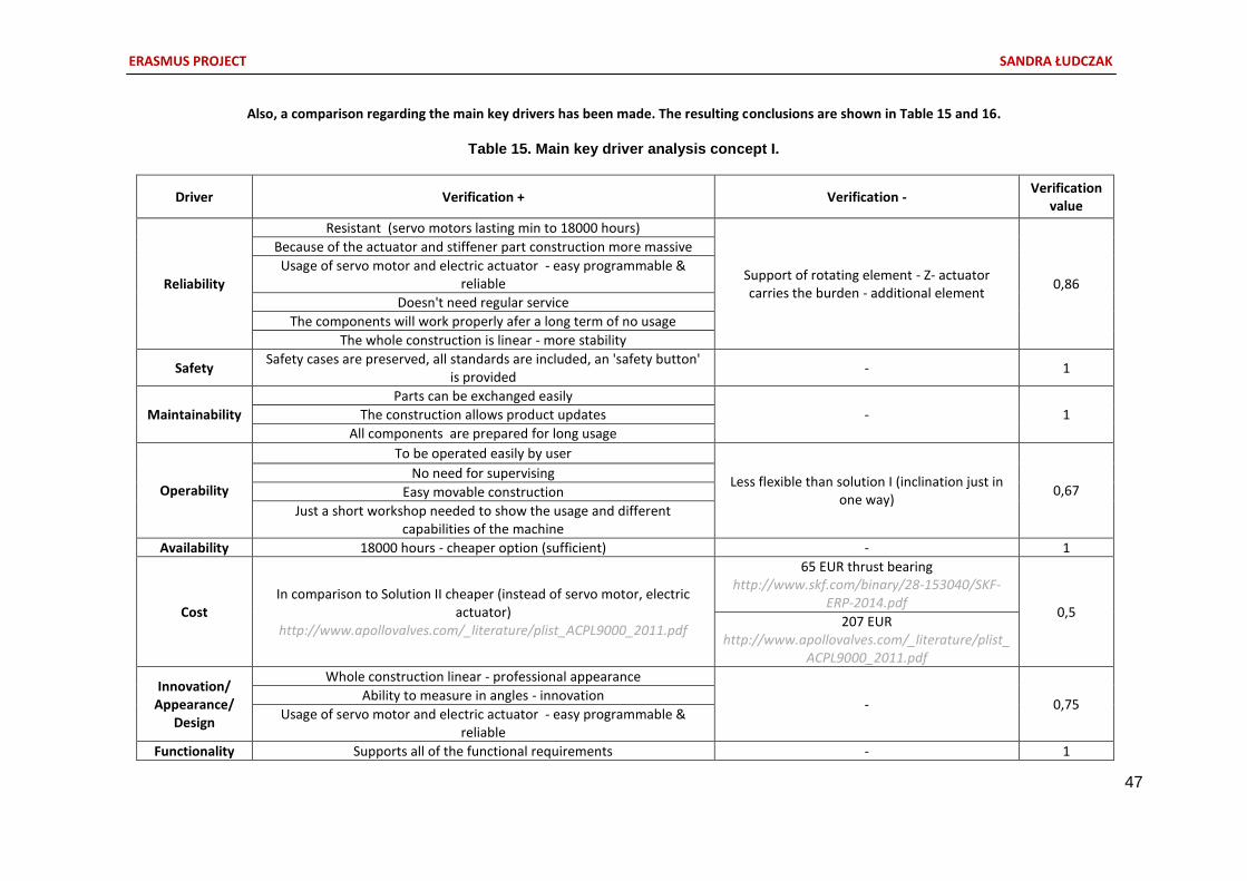
Also, a comparison regarding the main key drivers has been made. The resulting conclusions are shown in Table 15 and 16.
Table 15. Main key driver analysis concept I.
Driver Verification + Verification - Verification
value
Reliability
Resistant (servo motors lasting min to 18000 hours)
Support of rotating element - Z- actuator carries the burden - additional element
0,86
Because of the actuator and stiffener part construction more massive
Usage of servo motor and electric actuator - easy programmable & reliable
Doesn't need regular service
The components will work properly afer a long term of no usage
The whole construction is linear - more stability
Safety Safety cases are preserved, all standards are included, an 'safety button'
is provided - 1
Maintainability
Parts can be exchanged easily
- 1 The construction allows product updates
All components are prepared for long usage
Operability
To be operated easily by user
Less flexible than solution I (inclination just in one way)
0,67 No need for supervising
Easy movable construction
Just a short workshop needed to show the usage and different capabilities of the machine
Availability 18000 hours - cheaper option (sufficient) - 1
Cost In comparison to Solution II cheaper (instead of servo motor, electric
actuator) http://www.apollovalves.com/_literature/plist_ACPL9000_2011.pdf
65 EUR thrust bearing http://www.skf.com/binary/28-153040/SKF-
ERP-2014.pdf 0,5
207 EUR http://www.apollovalves.com/_literature/plist_
ACPL9000_2011.pdf
Innovation/ Appearance/
Design
Whole construction linear - professional appearance
- 0,75 Ability to measure in angles - innovation
Usage of servo motor and electric actuator - easy programmable & reliable
Functionality Supports all of the functional requirements - 1

ERASMUS PROJECT SANDRA ŁUDCZAK
48
Table 16. Main key driver analysis concept II.
Driver Verification + Verification - Verification
value
Reliability
Resistant (servo motors lasting up min to 30000 hours) Support of rotating element - Z- actuator carries the
burden - additional element
0,57 The construction is able to carry all the weight - material selection.
Insertion can occur - stability of lower rotation motor needed?
Construction doesn't need a systematic service Part that rotates placed on the side - less stable than
solution I The servo motors work properly while not being turned on for a long period of time
Safety Safety cases are preserved, all standards are included, an 'safety
button' is provided - 1
Maintaina - bility
Parts are easy exchangable
The exchange of parts can be time consuming 0,75 The actuators and servomechanisms needs to be exchanged (but the
period of time when it's needed to be exchanged is satisfying).
The construction allows product updates
Operability
Because of the servo motors is easy programmable
The time used to undergo one testing is more time consuming than solution nr I
0,8
No supervisor needed to operate the machine
Just a short workshop needed to show the usage and different capabilities of the machine
Device is easily movable
Availability 30000 hours minimum (sufficient) - 1
Cost dependent on the material and components - to be discussed
65 EUR thrust bearing (http://www.skf.com/binary/28-153040/SKF-ERP-2014.pdf)
0,4
645 EUR per piece for 30000hours, we need the half so cheaper
(http://hundtech.en.alibaba.com/product/60230045034-
800968131/Servo_motor_planetary_gearbox_with_30_000_hours_life_time.html),
Innovation/ Appearance/
Design
Ability to measure in angles - innovation Part that rotates placed on the side - no symetric; worse
appearance 0,75 Usage of servo motors - easy programmable & reliable
improved design
Functionality Supports all of the functional requirements - 1

ERASMUS PROJECT SANDRA ŁUDCZAK
49
3.3.3. Lower part selection
First, the main idea has been chosen. According to Chapter 3.2.3. there was a selection
among the already existing EVOLEO Technologies solution and the innovative solution using springs.
The construction have been analysed in accordance to the chosen key drivers shown in Table 1 (See
Chapter 2.1.1. Considering these values radar graphs have been created to compare the solutions.
The diagrams are based on proportions of positive and negative aspects that have been noticed. The
whole amount of factors equals 1. An percentage of the positive features has been calculated to
create graphs (positioned on the left side of each table). Then key drivers have been chosen and
values have been added to it concerning its importance for the construction. Table 1 shows the
conclusion. Later on, multiplying the percentage with the values, other diagrams were created so to
get the wanted conclusion. The Tables 17 and 18 show the path, the analysis was going through,
whilst Table 19 shows the resultant Diagram.
Table 17. Lower part spring solution analysis.
Driver Verification + Verification
- Verification
value
Reliability
Base fits perfectly with the products shape - individual for each new product
- 1 Construction stable in every case, can hold desired weight
Lateral stabilizators protect against bending of whole construction.
Safety Safety cases are preserved, all standards are included, an
'safety button' is provided - 1
Maintainability The construction allows product updates Springs
wear off 0,8
All components are prepared for long usage
Operability
Easily and fast exchangable due to springs used
- 1
Needle pad connected with part responsible for placing the product helps exchanging the part quickly
Simple construction - easy to replace parts
Just a short workshop needed to show the usage and different capabilities of the machine
No need for supervising
Availability No limits - 1
Cost Lower cost than older solution (no need to use electric
actuator to pull the needle pad up) - 0,6
Innovation Needs less components - simple design - 0,6
Functionality Supports all of the functional requirements - 1

ERASMUS PROJECT SANDRA ŁUDCZAK
50
Table 18. Lower part solution with actuator analysis.
Driver Verification + Verification
- Verification
value
Reliability
Base fits perfectly with the products shape - individual for each new product
Additional part (electric
actuator) equals less reliability
than spring solution
0,75
Construction stable in every case, can hold desired weight
Product placed very accurate because of a form corresponding with the products shape
Safety Safety cases are preserved, all standards are included,
an 'safety button' is provided - 1
Maintainability The construction allows product updates
- 1 All components are prepared for long usage
Operability
Easily and fast exchangable
- 1
Needle pad connected with part responsible for placing the product helps exchanging the part quickly
Just a short workshop needed to show the usage and different capabilities of the machine
No need for supervising
Simple construction - easy to replace parts
Availability No limits - 1
Cost -
More expensive in comparison to solution
using springs
0,4
Innovation/ Appearance/
Design -
More components
- complex design
0,4
Functionality Supports all of the functional requirements
1
Assuming that the values for Safety, Availability and Functionality must be equal 1 (otherwise
the machine would not make any sense) , radial diagrams have been created not containing them.

ERASMUS PROJECT SANDRA ŁUDCZAK
51
Table 19. Radial diagram comparison of lower parts.
Before weight summary After weight summary
After choosing the main idea it was necessary to emerge the best concept for the product’s
fixture. Therefore a SWOT analysis of the different concepts has been made. Table 20 shows the
winner solution – concept IV. It is because the most important criteria was the reliability factor of
the device.
Actuator
part
Spring
part

ERASMUS PROJECT SANDRA ŁUDCZAK
52
Table 20. SWOT analysis of holding part.
Concept I
Concept II
Concept III
Concept IV
Strengths
No need for a lot
of space
Fast exchange of
components
Exchangeable
endings – fitting
to each product
Simple
construction/ easy
operating
Just two actuators
needed for
solution to work
Weaknesses
A mechanism
needed to stand
up against the
springs which hold
the edges of the
product
Additional
elements needed
to move the clips
Trouble with
placing the
product in the
exact middle
Issue with non -
streamline items
(tape tearing
apart)
Tapes wear off
Few components
equals less
reliability
-
Opportunities - -
New invention on
the market =>
opportunities for
the company to
evolve
Solving problem
with cheap
outcome
Threads
Amount of
components –
complicated
construction
Tapes wear off
(on the corners
of the package)
Possible time
influence on tape
extension
Possible time
influence on tape
extension
Placement of
testing area
+ 1 1 2 3
- 3 4 3 1
SUM -2 -3 -1 2

ERASMUS PROJECT SANDRA ŁUDCZAK
53
3.4. Developing the main idea
3.4.1. Upper part development
The Upper part (EXCM XY – Table) from Festo company was put into the whole assembly in
order to show the different movement dependencies of the different parts. Each component of the
XY Table was given a new appearance (colour) in order to highlight the number of components it is
composed of. The XY – Table is shown in Figure.
Figure 32. EXCM XY – Table produced by Festo company (https://www.festo.com/cms/nl-
be_be/21917.htm).
The exploded view of the XY – Table is shown in Figure 32. It consists of 13 main parts, four
holding parts and few screws. The part marked as I is sliding on the surface of part II, enabling
horizontal movement. The part II on the other hand slides on part III allowing vertical movement.
Part marked as V is responsible for holding part II into the splint of part III. The components marked
as VI are parts to be connected with the motor causing the tables movement. Composition IV is used
four times in this assembly. It is responsible for placing the whole XY – Table onto a rigid, robust
structure.

ERASMUS PROJECT SANDRA ŁUDCZAK
54
Figure 33. Exploaded view of XY – Table.
3.4.2. Middle part development
Strength calculations have been made in order to verify if the chosen parts fulfil all desired
criteria. Optimization processes have been undergone in order to minimize the construction by
simultaneous maintenance of all requirements. Because of that process some parts have been
exchanged.
STRENGHT CALCULATIONS FOR EMMS-AS-40-S-LS-SRB SERVO MOTOR PLACED ABOVE TESTING
ENDINGS
The attached pneumatic actuator responsible for moving the endings can work under
pressure up to 6 bar which at this point is causing the theoretical force of 68 N [9]. Out of a linear
proportion it is possible to count the force at 3 and 4 bar (values used by EVOLEO Technology).
Because the maximum force used by the company is desired, the force is counted at 4 bar.
I
II
III
IV
VI
V

ERASMUS PROJECT SANDRA ŁUDCZAK
55
To check if this value is counted properly the underneath equation can be used:
[5]
Knowing that 1 bar = Pa, the diameter of the servos shaft = 12 mm and that the servo motor will
work under max. pressure 4 bar:
It needs to be considered that the pneumatic actuator while pushing a button applies that force,
which causes reaction force at the same amount. That is why this maximum force is considered
during calculating the torque which the servo motor responsible for rotation of the table attached to
the testing endings. Now it is important to count the distance from the centre of the mass on which
the force is applied. That is the distance between the shaft of the discussed servo motor and the
shaft of the pneumatic actuator. Knowing the dimensions of all the components and their weights it
is possible to define the centre of mass.
Figure 34. Explanation drawing.
The maximum weight the chosen servo motor must stand is 509 g. Assuming even weight
distribution the centroid should be placed in a position where on both sides there is 254,5g. Knowing
45 N
44 mm 29 mm 27 mm

ERASMUS PROJECT SANDRA ŁUDCZAK
56
that the servo motor is responsible for rotating the suction cup weights 380g through proportion it is
possible to calculate the centroid.
Now, knowing that the actuation part of the pneumatic actuator responsible for pushing the button
is placed in the middle of the actuator it is possible to calculate the distance between the shaft of the
servo motor and the shaft of the pneumatic actuator.
Figure 35. Explanation drawing.
The torque that the side set servo motor needs to stand is calculated using the underneath equation:
[6]
The selected servo motor EMMS-AS-40-S-LS-SRB turned out to be inadequate because of a too small
torque. That is why the need occur to change this component. The part was exchanged into a stepper
motor from Parker (LVHV341-01). This unit is able to provide a movement of 1,8° per impulse. It is
possible for the stepper motor to perform so called ‘half steps’ in order to get a rotation of 0,9° per
impulse.
STRENGTH CALCULATIONS FOR EMMS-AS-40-S-LS-SRB SERVO MOTOR ATTACHED TO Z - ACTUATOR
L
44 mm 29 mm 27 mm

ERASMUS PROJECT SANDRA ŁUDCZAK
57
BENDING AND TORQUE ANALYSIS
The selected servo motor has to overcome bending produced by the weight of the testing
endings together with its mounting (drawing b), the weight of the LVHV341-01 stepper motor and
also bending and torque caused by the reaction force of the pneumatic actuator (drawing a).
Figure 36. Explanation drawing.
From a) bending caused by the weight of the testing endings is calculated:
[7]
From b) It is considered that the table with actuators is situated under an angle of 90°. The force
from the pneumatic actuator causes torsion as well as bending:
[8]
b) B - B a)
, M3
Fg
20
68 mm
2 mm
40 mm
15 mm 65 mm

ERASMUS PROJECT SANDRA ŁUDCZAK
58
[9]
Radial forces that the selected servo motor should be able to stand 51,28N:
[10]
Also, it has to overcome a torque of T = 3,26 Nm.
The above mentioned requirements are fulfilled by the servo motor EMMS-AS-70-SK-LS-RSB from
Festo company, which stands 78 N radial forces and 7,75 Nm of torque [8].
The requirements are fulfilled.
STRENGHT CALCULATIONS FOR Z – ACTUATOR
The Z-actuator needs to stand the total weight of the construction and the torque produced
by the reaction force of the pneumatic actuator.
An actuator that fulfils the above mentioned requirements is EGSL-BS-45-100-3P from Festo
company. The documentation proves that the Z-actuator is able to carry 631N and stand a torque up
to 16,3Nm.
29,27 N
ERASMUS PROJECT SANDRA ŁUDCZAK
59
The requirements are fulfilled.
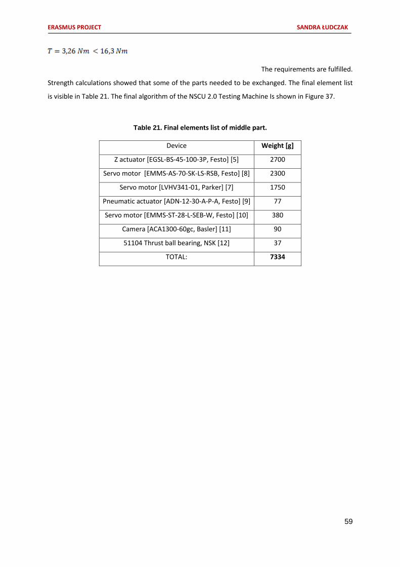
Strength calculations showed that some of the parts needed to be exchanged. The final element list
is visible in Table 21. The final algorithm of the NSCU 2.0 Testing Machine Is shown in Figure 37.
Table 21. Final elements list of middle part.
Device Weight [g]
Z actuator [EGSL-BS-45-100-3P, Festo] [5] 2700
Servo motor [EMMS-AS-70-SK-LS-RSB, Festo] [8] 2300
Servo motor [LVHV341-01, Parker] [7] 1750
Pneumatic actuator [ADN-12-30-A-P-A, Festo] [9] 77
Servo motor [EMMS-ST-28-L-SEB-W, Festo] [10] 380
Camera [ACA1300-60gc, Basler] [11] 90
51104 Thrust ball bearing, NSK [12] 37
TOTAL: 7334

ERASMUS PROJECT SANDRA ŁUDCZAK
60
Figure 37. Final algorithm of NSCU 2.0. Testing Machine.
MATERIAL SELECTION
In order to select an adequate material for the customized parts it was essential that these
parts would be resistant against pressure applied from all components. For this a situation is
considered in which each of the parts apply the highest possible force on the smallest possible area.
This area belongs to the shaft 341-01 parker servo actuator. The force Is a summary of the force
coming from the components situated below the servo and the force applied by the EMMS-ST-28
pneumatic actuator.
65,36 N

ERASMUS PROJECT SANDRA ŁUDCZAK
61
[11]
The chosen material must stand stress at minimum 516 kPa. Since the construction should also be
light, aluminium alloy 5052-0 has been chosen [23, 24, 25]. It has a good workability, is easy to
machine, is corrosion resistant and is used in sheet metals.
FIXTURE OF COMPONENTS
The 341-01 Parker stepper motor is a 1,8 degree stepper, so it needs 200 steps to make a full
revolution. Considering the longest testing actuator used (EMMS-ST-28), the distance between the
servo shaft and the end of the actuator has been calculated. That procedure was made in order to
examine the arc length which the actuator needs to overcome at a 1,8° displacement. The distance
between the 341-01 Parker shaft centre and the actuator ending equals 141,65mm. From the
equation [12] the arc length has been calculated.
[12]
This parameters are sufficient for the NSCU 2.0 Testing Machine.
In order to get a better operability of the testing endings the whole lower situated construction that
is rotatable was being placed higher. Because of that the distance between the 341-01 Parker
stepper motor shaft and the ending was lowered to 101.27 mm, which resulted in shortening the arc
length of the testing endings to 3.18 mm. Due to the possibility of programming the stepper motor
for performing ‘half steps’ (every 0,9°), the operating arc length per pulse equals 3.18/2 = 1.59 mm.
FINAL CONCEPT - CONSTRUCTION
4,45 mm

ERASMUS PROJECT SANDRA ŁUDCZAK
62
Changes to the previous concepts have been made in order to improve the design,
compactness, weight and reliability. The resulting appearance of the middle part is shown in
Figure 38.
Figure 38. Final concept of middle part. (1. maximum elongation, 2. maximum reduction of
component)
The pictures below explain how each individual part is situated in the assembly.
The EGSL-BS-45-100-3P actuator is connected to the EMMS-AS-70 servo motor through an purpose-
built element shown in Figure 39. It presses against the 51104 thrust bearing in order to cause load
transfer to the Z - actuator. Inside the bearing there is a bush, which ending is wider than the bearing
so it can move easily on the surface of the balls inside the thrust ball bearing.

ERASMUS PROJECT SANDRA ŁUDCZAK
63
Figure 39. Z - actuator to EMMS-AS-70 servo motor fixture.
Figure 40. Interior visualization of element connecting Z - actuator with EMMS-AS-70 servo motor.
Element
connecting the Z-
actuator with the
EMMS-AS-70
servo.
51104
Thrust ball
bearing

ERASMUS PROJECT SANDRA ŁUDCZAK
64
Figure 41. Bush inside thrust ball bearing.
Figure 42. Fixture of bush.
The 341-01 Parker stepper motor is fixed through an element shown in Figure 42.
Bush

ERASMUS PROJECT SANDRA ŁUDCZAK
65
Figure 43. 341-01 Parker step motor fixture.
The stepper motor 341-01 is attached to an element holding the testing endings (Figure 43).
341-01
stepper
motor fixture

ERASMUS PROJECT SANDRA ŁUDCZAK
66
Figure 44. Expansed views of middle part.
The front view of the above shown elements is presented in Figure 44.
Screw
responsible
for
establishing
the step
motor’s shaft
A

ERASMUS PROJECT SANDRA ŁUDCZAK
67
Figure 45. Front view of middle part.
The AND-30-P pneumatic actuator is connected to the rotatable platform through four screws. The
EMMS-ST-28 servo motor (left) and camera (right) fixture is shown in Figure 46.
A
EMMS-ST-
28 servo
motor fixture
Shaft
Camera

ERASMUS PROJECT SANDRA ŁUDCZAK
68
Figure 46. Fixture of pneumatic actuator and camera.
Figure 47. EMMS-ST-28 servo motor fixture

ERASMUS PROJECT SANDRA ŁUDCZAK
69
The exploded view of the middle part is shown in Figure 48. The middle part is composed of 7
main units (see Table 22 and Figure 42). All parts that are not mentioned were customized especially
for the need of this project. 27 screws have been used to connect all the parts together. Mostly it
have been socket head cup screws at various sizes.

ERASMUS PROJECT SANDRA ŁUDCZAK
70
Figure 48. Exploaded views of middle part.
1
1
2
2
Z - actuator
[EGSL-BS-45-100-3P, Festo]
Servo motor
[EMMS-AS-70-SK-LS-RSB, Festo]
Servo motor [LVHV341-01, Parker]
Pneumatic actuator [ADN-12-30-A-P-A, Festo]
Servo motor [EMMS-ST-28-L-SEB-W, Festo]
Camera [ACA1300-60gc, Basler]
51104 Thrust ball bearing, NSK
Part for immobilizing ball bearing
Connector for EMMS-AS-70
servo to bearing
Bush inside bearing
Washer
Fixture for EMMS-ST-28 servo
Connector between camera, EMMS-ST-28, ADN-30-Pa and 341-01
servo

ERASMUS PROJECT SANDRA ŁUDCZAK
71
3.4.3. Lower part development
Since the Preliminary Design phase of the project, the Lower part has been improved. It was
to be assumed that in order to improve the machine, some of the older versions need to be lowered
in the number of components. That is why the mechanism, which was used to connect and
disconnect the DUT fixture with the needle pad differs completely from the new, innovative solution.
In order to reduce the number of elements the connection and disconnection is realized by an
opening door flap as shown in Figure 50. The Lower part consists of 27 units shown in Figure 49. All
components of which the Lower part consists are customized units.
Figure 49. Exploaded view of Lower part.
Handle
DUT (Device Under Test)
Needles
Plate for DUT placement
Grasper (Hinge movement)
Fixture of DUT placement
plate
Needle pad
Compression spring x4
Roller x2
Security cotter x4
Door flap connector x2
Metal rope connector (hinge movement)

ERASMUS PROJECT SANDRA ŁUDCZAK
72
The final, improved Universal Functional Tester is shown in Figure 50. It is composed of five
different sub – assemblies: so called Upper part, Middle part, Lower part, Structure (corps) and
movable door which is responsible for the closure mechanism of the DUT fixture and needle pad.
Figure 50. Final appearance of the optimised Universal Functional Tester.
The machines corps is a solid structure composed of aluminium profiles that have
a special shape allowing its connection without any effort and being very reliable at the same time.
The profile is shown in Figure 51.
Figure 51. Aluminium profiles cross – section.

ERASMUS PROJECT SANDRA ŁUDCZAK
73
The different sections of the Machine are shown in Figure 52. It is possible to see the
different sub – sets which have been discussed before.
Figure 52. Section views of improved Universal Functional Tester.
In order to visualise the different sub – assemblies Figures below are being showed.

ERASMUS PROJECT SANDRA ŁUDCZAK
74
1) Structure
Figure 53. Aluminium profile structure (exploaded view).
2) Upper part
Figure 54. Upper part sub – assembly: XY – Table.
XY – Table to
structure fixture
Aluminium
profile
Roller for
metal wire x2

ERASMUS PROJECT SANDRA ŁUDCZAK
75
3) Middle part
Figure 55. Middle part sub – assembly .
4) Lower part
Figure 56. Lower part sub – assembly with movable door flap.

ERASMUS PROJECT SANDRA ŁUDCZAK
76
5) Movable door
Figure 57. Door sub - assembly (1 - normal view, 2 - exploaded view).
A set of illustrations has been made (Figure 58) in order to show the following steps of
placing the DUT into the desired position as well as connecting the DUT fixture with the needle
pad.
1 2 Door hinge 2x
Door flap
connector x2
Metal rope connector
(hinge movement)

ERASMUS PROJECT SANDRA ŁUDCZAK
77
Figure 58. Consecutive steps while positioning the DUT.
1
2
3
4
4
4

ERASMUS PROJECT SANDRA ŁUDCZAK
78
Special holes have been designed for the spring to hide while being compressed.
Figure 59. Holes responsible for covering the compressed springs while connecting DUT
fixture with needle pad.
The mechanism causing connection of the DUT with the needle pad is presented below. It
is to be mentioned that regarding the fact that potential users could slam the door (resulting with
problems occurring at the needle connection part) a safety system is used to prevent too fast door
shut closure. The end of the door is equipped into spring cylinders that smoothen the closure of
the door in case of slumming it. Additional, the black grip visible in Figure 60 is laden with weight so
to help the ordinary user by dealing with the doors weight. When the door is placed in a position
exceeding 90° it automatically goes up and holds itself in the air. On the other hand, when the door
is positioned below 90° it helps the user to easy close the door. Also, It needed to be calculated at
which position the steel wire should be mounted. Knowing that the best possible option is to have
a isosceles triangle (45°) and that the distance between the DUT fixture and needle pad while being
disconnected equals 160, a simple calculation has been made in order to get best distance for
mounting the wire.
45°
45° .
160 a
113,14 mm

ERASMUS PROJECT SANDRA ŁUDCZAK
79
While the door is being pushed down, the metal wire causes rotation on the roller which
indicates the movement of the needle pad construction.
The whole movement is resulting with the closure of two components – the needle pad and the
product.
Figure 60. DUT fixture to needle pad connection mechanism.
1
4
2
3
Needle pad
Product
Weight loaded grip
Spring cylinder x2

ERASMUS PROJECT SANDRA ŁUDCZAK
80
3.5. Budgeting
All components have been summarized below (Table 22) in order to receive a demonstrative
price list. Some of the prices have been taken from websites of the producers, others have been
approximated by the knowledge of employees working at EVOLEO Technologies.
Table 22. Price list of NSCU 2.0 Universal Functional Tester.
Device Quantity Cost (euro)
XY – Table [EXCM, Festo] 1 1500,00**
Z actuator [EGSL-BS-45-100-3P, Festo] [10] 1 1065,00*
Servo motor [EMMS-AS-70-SK-LS-RSB, Festo]
[8] 1 792,40*
Servo motor [LVHV341-01, Parker] [7] 1 271,70*
Pneumatic actuator [ADN-12-30-A-P-A, Festo]
[9] 1 115,40*
Servo motor [EMMS-ST-28-L-SEB-W, Festo]
[13] 1 142,35*
Camera [ACA1300-60gc, Basler] [14] 1 440,00*
51104 Thrust ball bearing, NSK [15] 1 10,50*

ERASMUS PROJECT SANDRA ŁUDCZAK
81
Customized units:
Connector for 341 – 01 servo to testing
endings
Fixture for EMMS – ST – 28 servo
Fixture for 341 – 01 servo
Unit for immobilizing thrust ball bearing Bush inside bearing
Washer Connector for EMMS-AS-70 servo to thrust
ball bearing
Sheet metal (Middle part fixture)
XY – Table to structure fixture
Steel wire
Roller
Door with hinges
Needle pad fixture to steel wire connector Door to steel wire connector
1
1
1
1 1 1 1
1
1
2
2
1x2
2 2
500*

ERASMUS PROJECT SANDRA ŁUDCZAK
82
Screws and nuts
1 package (100)
Aluminium profile
(10pcs 600mm +10pcs 650mm+ 4pcs
L730mm) [16]
20 54,44*
(price for 20)
DUT fixture and needle pad connector
mechanism cassette 1 1000**
Additional costs:
work payment (employees),
production,
new design,
additional elements,
electrical devices,
motors etc.
30000*
TOTAL: 35891,79
*Currency conversion from pounds to euros **price taken from consultation with EVOLEO Technologies employees
The overall cost of NSCU2.0 (including components, new design and production) equals
35891,79 euro. The NSCU1.0 (previous Universal Functional Tester) oscillated around 40,000
euros.
3.6. Critical analysis and prospects for improvement
Summing up the whole work process I think that regarding the fact that this was the first
time I had to deal with a project, the results achieved are satisfying. Two completely new parts
have been created, it was possible to make the machine measure in angles and the DUT fixture to
needle pad connection mechanism was being improved. That is, I would say, a good outcome. If
I would start the project again I would definitely distinguish which concepts are possible to realise
and which ones are almost impossible to achieve. My knowledge about the technical aspects
expanded a lot and for sure the next project would take a shorter time to being brought into
reality.

ERASMUS PROJECT SANDRA ŁUDCZAK
83
If I was asked about improving the project in present I could only think about the DUT
fixture and needle pad connecting mechanism improvement (which equalize with a cost rise).
Instead of using rollers upon which steel wires that connect the door with the needle pad holding
are placed, double - acting hydraulic cylinders could be used. As the door would be closing, the
liquid would move actuating the needle pad fixture to connect with the DUT. On the other hand,
while opening the door the exact opposite situation would take place – the mentioned devices
would be disconnected.
3.7. Equipment instructions manual
Since the work was based on improving the already existing NSCU1.0 Universal Functional
Tester and regarding that a few components have been exchanged, others have remained, the
Manual Instruction guide was not changed. No important changes (from the view of the user) have
been implemented. For more information about the content of the Manual it is necessary to reach
for the Equipment Instructions Manual NSCU Descrição da operação do Sistema.
3.8. Maintenance Guidelines
Table of Contents Introduction ................................................................................................................................. 1
Testing and solving problems ........................................................................................................ 4
Machine does not turn on...................................................................................... 5
The vision system does not work ........................................................................... 6
The DUT does not fit ............................................................................................. 5
XY – Table does not work ...................................................................................... 6
Conservating/ cleaning ................................................................................................................. 1
List of components ....................................................................................................................... 4
Introduction
This document was created in order to explain processes that are necessary for maintaining
the equipment of the NSCU 2.0 Testing Machine.
The NSCU 2.0 Testing Machine is composed of a universal platform used to test the buttons,
rotary switches and displays of different devices. Figure 1 shows the machine.

ERASMUS PROJECT SANDRA ŁUDCZAK
84
Figure 1. NSCU Functional Tester.
Testing and solving problems
This section is dedicated to problem solving of errors that could occur during the usage of
NSCU 2.0 Functional Tester.
In each situation it is to be assumed that errors from the site of the software may occur. That
is why it is to be assured that the problem does not results from the failure of the software.
Before proceeding with the problem solving it is to be assured that all pneumatic actuators
are blocked in order not to cause harm to the user.
Table 1. Dealing with errors.
Procedure Respond Solution
1. The Machine does not turn on
Check if the integrated
switches X1, X2, X3 are
switched on
YES
NO
Proceed to next step
Switch on the switches
Check if all the cables are
plugged in properly
YES
NO
Proceed to next step
Plug in all cables
Check if the UPS is connected YES Proceed to next step

ERASMUS PROJECT SANDRA ŁUDCZAK
85
NO Connect the UPS
Check if the ON/OFF switch is
damaged. To do so remove the
panel that contains the switch.
Place the switch in a device
that verifies if there is
communication between all
pins.
YES
NO
Exchange the switch
Contact the service for
assistance.
2. The vision system does not work
Open the MAX software and
verify if the camera is
connected
YES
NO
Proceed to next step
Connect the camera
Use a button to verify if the
camera is showing the desired
image correctly
YES
NO
Verify if the camera is
corresponding to the MAX
software
Proceed to next step
Check if the Ethernet cable
between the computer and the
camera is plugged in correctly
YES
NO
Proceed to next step
Plug in the cable
Verify if the lens is placed onto
the camera
YES
NO
Contact the service for
assistance.
Put the lens onto the camera
3. The DUT does not fit
Check if anything is in-between
the DUT and the connection
part
YES
NO
Pull out the colliding element
Proceed to next step
Use the special prepared
system responsible for verifying
if the part is reacting correctly.
YES
NO
Proceed to next step
Check if the DUT’s pins are
reacting (Yes - Proceed to next
step, No – exchange the
damaged pin)

ERASMUS PROJECT SANDRA ŁUDCZAK
86
Check if the system is sending
an information about the
connected voltage (proper
values: 2V, 3.3V)
YES
NO
Contact the service for
assistance.
Write an command including
the desired voltage
4. XY – Table does not work
Connect the software of FESTO
in order to verify if controllers
are working properly
YES
NO
Contact the service for
assistance.
Exchange
Conservating/ cleaning
The cleaning process should be done under the strict shut down of the equipment. The areas
that should be cleaned are the needle pad part – placed onto the DUT and the ventilation system
which is located in the inner side part of the top panel. To do that it is recommended to exchange the
attached filter.
List of components
Figure 2. Components chart of NSCU 2.0 Testi ng Machine.

ERASMUS PROJECT SANDRA ŁUDCZAK
87

ERASMUS PROJECT SANDRA ŁUDCZAK
88
4. CONCLUDING REMARKS

ERASMUS PROJECT SANDRA ŁUDCZAK
89
4. Concluding remarks
The project being presented with this work was my first of that kind. That is why I have
encountered a lot of problems which in the first place seemed to be very easy to solve. After
writing this report I have realized that it is more difficult to optimize an already existing device than
to build one from scratch. That is because while You are looking at a certain problem having
already the previous results it is harder to think ‘out of the box’. Previous designs seem to be ideal
because everything was working as it should. Also, the computer - aided engineering software
Solidworks was a new environment for me. Because of this I have spent a lot of time in tutorials
rather than concentrating on the problem at the beginning (which was good for me because right
now I can use this tool in a lot of aspects). After the time accommodating to the form of this
project and also after familiarization with the Solidworks environment everything was easier. New
concepts came into my mind very quickly and everything seemed more organised and clear. The
achieved results in this project were satisfying, though. Two completely new parts have been
created, it was possible to make the machine measure in angles and the DUT fixture with needle
pad connection mechanism was being improved. That is, I would say, a good outcome. I have
gained a lot of new skills, learning Solidworks, business language, different Product Development
Processes, how to accommodate in a company etc.
It was the first time for me to work with Portuguese people, but I have to admit that it was
a pleasure to be given a chance like that. Right away when I entered EVOLEO Technologies (the
company I was realizing my project at) I was greeted with smiles and interest about my person. The
first impression was great. The work also was very good. Always when I needed help someone was
there to give me advices. I never encountered uncomfortable situations and I could easily talk
about all my doubts or problems. The chefs are open for new ideas and are trying to do their best
in order for everyone to be satisfied. Also, besides the job, me and my work colleagues went out
several times. It was a great experience.
If it comes to the university, I have to say that being part of the ISEP Master Degree in
Mechanical Engineering was the best thing that could actually happen to me. It was the first time
I encountered that a department takes so much care about students. Since the arrival we were
being welcomed with food and music, after that we got propositions to realize our Erasmus
Projects in companies, what rises our attractiveness in the work life and gives us great experiences.
Together with Professor Francisco J. G. Silva we have been having meetings in companies. The
contact between us was great. Professor Silva answered our E – Mails very fast, always assured
himself if everything was all right and was a really big help to all us Erasmus Students from Poland.
We were glad to have him.

ERASMUS PROJECT SANDRA ŁUDCZAK
90
My Erasmus+ experience in Porto was amazing. The city is beautiful (I have been doing a lot
of sightseeing through whole Portugal), the people are awesome (when I got lost somewhere there
was always a person to help me find the way!), the food is different (cheese, wine and coffee are
AMAZING!) and the weather is perfect. I made a lot of friendships which I hope to keep in the
future. Also, from the educational aspect I have gained a lot. I have learnt new things about
Management, Manufacturing Processes, Product Development, requirement factors and have
managed to learn how to use different Solidworks tools. In my opinion this particular student
exchange program was a huge success.

ERASMUS PROJECT SANDRA ŁUDCZAK
91
5. SOURCES OF INFORMATION

ERASMUS PROJECT SANDRA ŁUDCZAK
92
5. Bibliography and others sources of information
BOOKS:
Dietrich M., Podstawy Konstrukcji Maszyn, Tom 1, Wydawnictwo Naukowo – Techniczne, 1999
Mały Poradnik Mechanika, Tom 1, Wydawnictwa Naukowo Techniczne , 1999
Niezgodziński Michał E., Niezgodziński T., Wytrzymalość materiałówPWN, Warszawa, 2002.
WEBPAGES:
[1] http://evoleotech.com/company/
[2]http://www.businessdictionary.com/
[3]https://www.linkedin.com/pulse/what-do-we-know-design-who-envolved-here-james-pacala-
capalar
[4]https://prezi.com/sd6bmkhqstld/untitled-prezi/
[5]https://www.festo.com/net/SupportPortal/Files/13541/Sicherheitstechnik%20135242%20201
3-03%20EN%20S.pdf p.12
[6]http://www.thomsonlinear.com/micro/conversion_eng/why-electric.html
[7]https://festo.direct/Pneumatic-drives/Linear-actuators/Compact-cylinder-ADN/p/536295
[8] https://www.festo.com/cat/pl_pl/data/doc_engb/PDF/EN/EMMS-AS_EN.PDF
[9]https://festo.direct/medias/PDF-EN-ADN
EN.PDF?context=bWFzdGVyfGZlc3RvLWNhdGFsb2ctbWVkaWF8MTM3OTc4MXxhcHBsaWNhdGlv
bi9wZGZ8ZmVzdG8tY2F0YWxvZy1tZWRpYS9oNTcvaDFkLzg3OTc3NjI3ODEyMTQucGRmfGM0YTc4
ZTZmMzI3MGE3YjMzMTdmMjU0MGY4ZDRiNzQ4OGRjNDdiOTQ2YjlmNTM2MTU0YWMyMDkxM
WRhOTBjYjM
[10]https://www.festo.com/net/SupportPortal/Files/212956/13_1-18%20-
%20Stepper%20motors%20EMMS-ST_ENUS.PDF
[11] http://www.baslerweb.com/en/products/area-scan-cameras/ace/aca1300-60gc
[12]http://nsk-jp.partcommunity.com/portal/auth/portal/nsk-
jp#!prjpathinfo=nsk_rb%2Froller_bearings%2Fthrust_bearings%2Fsingle_direction_tbb%2Fwith_f
lat_seet_asmtab.prj
[13] https://www.festo.com/cat/nl-be_be/data/doc_engb/PDF/EN/EGSL_EN.PDF
[14] https://graftek.biz/products/basler-aca1300-60gc-1-slash-1-dot-8-in-format-c-mount-1280-
x-1024-60-fps-color-cmos-global-shutter-gige-vision-poe

ERASMUS PROJECT SANDRA ŁUDCZAK
93
[15] http://uk.rs-online.com/web/p/ball-bearings/4090877/
[16]http://www.aliexpress.com/item/8pcs-600mm-6pcs-650mm-4pcs-730mm-20x20-aluminium-
profile/1301925744.html?spm=2114.40010508.4.67.Iah8qQ

ERASMUS PROJECT SANDRA ŁUDCZAK
94
6. APPENDIXES

ERASMUS PROJECT SANDRA ŁUDCZAK
95
6. Appendixes
Attachement 1. Requirement list - Universal Functional Tester 2.0.

ERASMUS PROJECT SANDRA ŁUDCZAK
96

ERASMUS PROJECT SANDRA ŁUDCZAK
97

ERASMUS PROJECT SANDRA ŁUDCZAK
98

ERASMUS PROJECT SANDRA ŁUDCZAK
99