
Optimisation of an Electroporation Device for Mashbibliothek.fzk.de/zb/veroeff/71864.pdf · and...
6
Optimisation of an Electroporation Device for Mash M. Sack, and G. Müller Forschungszentrum Karlsruhe GmbH Institut für Hochleistungsimpuls- und Mikrowellentechnik, Postfach 3640, D-76021 Karlsruhe, Germany Phone: +49-7247-82-4667, Fax: +49-7247-82-2823, E-mail: [email protected] Abstract – Electroporation is a new way for the mash treatment in the course of the vinification process. To inves- tigate the characteristics of this method in 2003 a mobile electroporation device for mash treatment has been built. In 2007 some improvements on this device have been per- formed in order to solve problems with blocking of the mash and tripping of the residual current protective device (RCD). A re-design of the piping system for the mash in- cluding the electroporation reactor and the method of pres- sure regulation became necessary. As a reason for tripping of the RCD pulse currents in the ground system caused by a switching process could be identified. A delayed switching of a group of devices reduced the energy of this pulse current below the sensitivity threshold of the RCD. The experiments performed during the wine campaign 2007 showed the suc- cess of the modifications. The paper describes the imple- mentation of the mentioned measures into the electropora- tion device. Index Terms - Electroporation, wine, mash, Marx genera- tor. I. INTRODUCTION Since 2001 the electroporation of mash of wine grapes has been investigated. Electroporation offers the opportu- nity to open the biological cells of the gapes' skin and pulp in order to extract gustatory substances and in the case of red wine grapes pigments fast and carefully, [1]. To extract the red color, traditionally, the cell membranes are opened by fermentation. This method is considered to guarantee the best quality of the wine. But this process takes several days. To speed up the process for a more efficient production, a thermal treatment of the grapes is used. The mash is heated up to approximately 80 °C and kept at this temperature for around two minutes. After- wards, the mash needs to be cooled down rather quick, because extensive heat has an influence on the flavor. Alternatively, enzymes may be used, but they are more expensive. II. ELECTROPORATION Electroporation is a physical method that may combine the advantages of fast processing at low temperature level. Hence, it preserves the original flavor of the wine. If an electric field is established across a biological cell, the cell membrane is charged by a current flowing through the cytoplasm. So the originally applied field is amplified across the membrane, especially at the areas oriented nearly normally to the electric field vector. Ac- cording to a widely accepted model under a sufficiently high local field the phospholipid molecules forming the bilayer of the cell membrane start to form a pore. If the electric field across the membrane is high enough, the pore grows. Smaller pores may close after switching off the external field. For higher applied field strengths irre- versible pores are formed. Through these pores, sub- stances may be extracted from the cell. The factor of the field enhancement across the membrane depends on the diameter of the cell. With a diameter in the order of 10-20 μm the cells of wine grapes are rather small. In the case of red wine, additionally the even smaller vacuoles con- taining the pigments must be opened. According to the experimental results of the last years for a good extraction of the pigments at a pulse length in the order of 1 to 1.5 μs a maximum field strength in the order of 50 kV/cm is required, [2]. Fig. 1: Mobile electroporation device for mash after the refurbishment. III. THE ELECTROPORATION DEVICE KEA-WEIN The mobile electroporation device KEA-WEIN has been built in the year 2003 by the company KEA-TEC in a joint project on the treatment of mash based on knowl- edge on electroporation and pulsed power technology by Forschungszentrum Karlsruhe. It is equipped with an air insulated six-stage Marx generator, a high-voltage power supply, and an electroporation reactor for mash. The
Transcript of Optimisation of an Electroporation Device for Mashbibliothek.fzk.de/zb/veroeff/71864.pdf · and...
Optimisation of an Electroporation Device for Mash
M. Sack, and G. Müller
Forschungszentrum Karlsruhe GmbH Institut für Hochleistungsimpuls- und Mikrowellentechnik,
Postfach 3640, D-76021 Karlsruhe, Germany Phone: +49-7247-82-4667, Fax: +49-7247-82-2823, E-mail: [email protected]
Abstract – Electroporation is a new way for the mash treatment in the course of the vinification process. To inves-tigate the characteristics of this method in 2003 a mobile electroporation device for mash treatment has been built. In 2007 some improvements on this device have been per-formed in order to solve problems with blocking of the mash and tripping of the residual current protective device (RCD). A re-design of the piping system for the mash in-cluding the electroporation reactor and the method of pres-sure regulation became necessary. As a reason for tripping of the RCD pulse currents in the ground system caused by a switching process could be identified. A delayed switching of a group of devices reduced the energy of this pulse current below the sensitivity threshold of the RCD. The experiments performed during the wine campaign 2007 showed the suc-cess of the modifications. The paper describes the imple-mentation of the mentioned measures into the electropora-tion device.
Index Terms - Electroporation, wine, mash, Marx genera-tor.
I. INTRODUCTION Since 2001 the electroporation of mash of wine grapes
has been investigated. Electroporation offers the opportu-nity to open the biological cells of the gapes' skin and pulp in order to extract gustatory substances and in the case of red wine grapes pigments fast and carefully, [1]. To extract the red color, traditionally, the cell membranes are opened by fermentation. This method is considered to guarantee the best quality of the wine. But this process takes several days. To speed up the process for a more efficient production, a thermal treatment of the grapes is used. The mash is heated up to approximately 80 °C and kept at this temperature for around two minutes. After-wards, the mash needs to be cooled down rather quick, because extensive heat has an influence on the flavor. Alternatively, enzymes may be used, but they are more expensive.
II. ELECTROPORATION Electroporation is a physical method that may combine
the advantages of fast processing at low temperature level. Hence, it preserves the original flavor of the wine. If an electric field is established across a biological cell, the cell membrane is charged by a current flowing through the cytoplasm. So the originally applied field is amplified across the membrane, especially at the areas
oriented nearly normally to the electric field vector. Ac-cording to a widely accepted model under a sufficiently high local field the phospholipid molecules forming the bilayer of the cell membrane start to form a pore. If the electric field across the membrane is high enough, the pore grows. Smaller pores may close after switching off the external field. For higher applied field strengths irre-versible pores are formed. Through these pores, sub-stances may be extracted from the cell. The factor of the field enhancement across the membrane depends on the diameter of the cell. With a diameter in the order of 10-20 µm the cells of wine grapes are rather small. In the case of red wine, additionally the even smaller vacuoles con-taining the pigments must be opened. According to the experimental results of the last years for a good extraction of the pigments at a pulse length in the order of 1 to 1.5 µs a maximum field strength in the order of 50 kV/cm is required, [2].
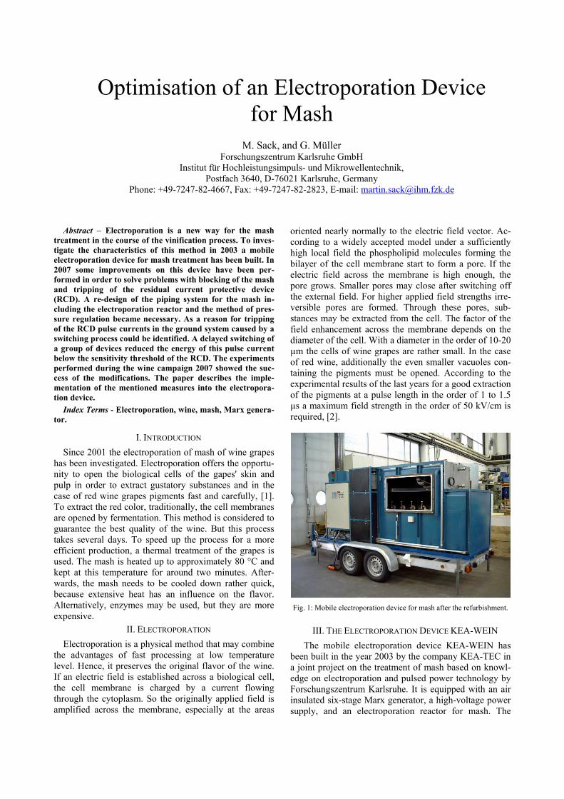
Fig. 1: Mobile electroporation device for mash after the refurbishment.
III. THE ELECTROPORATION DEVICE KEA-WEIN The mobile electroporation device KEA-WEIN has been built in the year 2003 by the company KEA-TEC in a joint project on the treatment of mash based on knowl-edge on electroporation and pulsed power technology by Forschungszentrum Karlsruhe. It is equipped with an air insulated six-stage Marx generator, a high-voltage power supply, and an electroporation reactor for mash. The
Marx generator has a stage capacitance of 140 nF and can be operated at a charging voltage of up to 50 kV per stage. It has been designed to run at a repetition rate of up to 20 Hz. The Marx generator is grounded at the center between stage three and four to deliver a voltage pulse symmetric to ground. So the minimum distance to the walls required for the insulation could be reduced. The spark gaps of the Marx generator are operated in nitrogen gas inside an insulating pipe to prevent oxidation, espe-cially the generation of nitrogen oxide. A fan blows the nitrogen gas in a closed loop through the whole spark gap pipe and a heat exchanger. The gas flow cools the spark gaps and removes the charge carriers from the spark gaps between the pulses. The heat exchanger is cooled by a cooling unit via an internal water circuit. The center spark gap, e.g. the spark gap between stage three and four has a slightly reduced gap distance in order to initiate the switching process of the Marx generator. The breakdown voltage is determined by its gap distance and fine tuned by the nitrogen gas pressure. The pressure can be varied between 1.0 and 1.5 barabs.
Fig. 2: Schematic of the pulse circuit: Marx generator grounded be-tween stage 3 and 4.
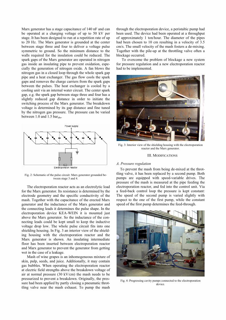
The electroporation reactor acts as an electrolytic load for the Marx generator. Its resistance is determined by the electrode geometry and the specific conductivity of the mash. Together with the capacitance of the erected Marx generator and the inductance of the Marx generator and the connecting leads it determines the pulse shape. In the electroporation device KEA-WEIN it is mounted just above the Marx generator. So the inductance of the con-necting leads could be kept small to keep the inductive voltage drop low. The whole pulse circuit fits into one shielding housing. In Fig. 3 an interior view of the shield-ing housing with the electroporation reactor and the Marx generator is shown. An insulating intermediate floor has been inserted between electroporation reactor and Marx generator to prevent the generator from getting wet in the case of a leakage.
Mash of wine grapes is an inhomogeneous mixture of skin, pulp, seeds, and juice. Additionally, it may contain gas bubbles. When operating the electroporation reactor at electric field strengths above the breakdown voltage of air at normal pressure (30 kV/cm) the mash needs to be pressurized to prevent a breakdown. Originally, the pres-sure had been applied by partly closing a pneumatic throt-tling valve near the mash exhaust. To pump the mash
through the electroporation device, a peristaltic pump had been used. The device had been operated at a throughput of approximately 1 ton/hour. The diameter of the pipes had been chosen to 10 cm resulting in a velocity of 3.5 cm/s. The small velocity of the mash fosters a de-mixing. Together with the pile-up at the throttling valve often a blockage occurred.
To overcome the problem of blockage a new system for pressure regulation and a new electroporation reactor had to be implemented.
Fig. 3: Interior view of the shielding housing with the electroporation reactor and the Marx generator.
III. MODIFICATIONS
A. Pressure regulation To prevent the mash from being de-mixed at the throt-
tling valve, it has been replaced by a second pump. Both pumps are equipped with speed-variable drives. The pressure of the mash is measured at the pipe feeding the electroporation reactor, and fed into the control unit. Via a feed-back control loop the pressure is kept constant: The speed of the second pump is varied slightly with respect to the one of the first pump, while the constant speed of the first pump determines the feed-through.
Fig. 4: Progressing cavity pumps connected to the electroporation device.
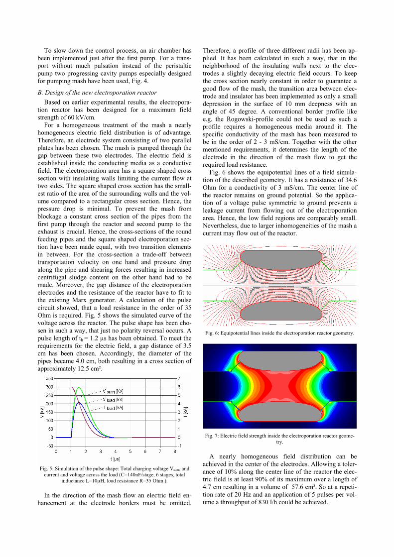
To slow down the control process, an air chamber has been implemented just after the first pump. For a trans-port without much pulsation instead of the peristaltic pump two progressing cavity pumps especially designed for pumping mash have been used, Fig. 4.
B. Design of the new electroporation reactor Based on earlier experimental results, the electropora-
tion reactor has been designed for a maximum field strength of 60 kV/cm.
For a homogeneous treatment of the mash a nearly homogeneous electric field distribution is of advantage. Therefore, an electrode system consisting of two parallel plates has been chosen. The mash is pumped through the gap between these two electrodes. The electric field is established inside the conducting media as a conductive field. The electroporation area has a square shaped cross section with insulating walls limiting the current flow at two sides. The square shaped cross section has the small-est ratio of the area of the surrounding walls and the vol-ume compared to a rectangular cross section. Hence, the pressure drop is minimal. To prevent the mash from blockage a constant cross section of the pipes from the first pump through the reactor and second pump to the exhaust is crucial. Hence, the cross-sections of the round feeding pipes and the square shaped electroporation sec-tion have been made equal, with two transition elements in between. For the cross-section a trade-off between transportation velocity on one hand and pressure drop along the pipe and shearing forces resulting in increased centrifugal sludge content on the other hand had to be made. Moreover, the gap distance of the electroporation electrodes and the resistance of the reactor have to fit to the existing Marx generator. A calculation of the pulse circuit showed, that a load resistance in the order of 35 Ohm is required. Fig. 5 shows the simulated curve of the voltage across the reactor. The pulse shape has been cho-sen in such a way, that just no polarity reversal occurs. A pulse length of th = 1.2 µs has been obtained. To meet the requirements for the electric field, a gap distance of 3.5 cm has been chosen. Accordingly, the diameter of the pipes became 4.0 cm, both resulting in a cross section of approximately 12.5 cm².
Fig. 5: Simulation of the pulse shape: Total charging voltage Vsum, and
current and voltage across the load (C=140nF/stage, 6 stages, total inductance L=10µH, load resistance R=35 Ohm ).
In the direction of the mash flow an electric field en-
hancement at the electrode borders must be omitted.
Therefore, a profile of three different radii has been ap-plied. It has been calculated in such a way, that in the neighborhood of the insulating walls next to the elec-trodes a slightly decaying electric field occurs. To keep the cross section nearly constant in order to guarantee a good flow of the mash, the transition area between elec-trode and insulator has been implemented as only a small depression in the surface of 10 mm deepness with an angle of 45 degree. A conventional border profile like e.g. the Rogowski-profile could not be used as such a profile requires a homogeneous media around it. The specific conductivity of the mash has been measured to be in the order of 2 - 3 mS/cm. Together with the other mentioned requirements, it determines the length of the electrode in the direction of the mash flow to get the required load resistance.
Fig. 6 shows the equipotential lines of a field simula-tion of the described geometry. It has a resistance of 34.6 Ohm for a conductivity of 3 mS/cm. The center line of the reactor remains on ground potential. So the applica-tion of a voltage pulse symmetric to ground prevents a leakage current from flowing out of the electroporation area. Hence, the low field regions are comparably small. Nevertheless, due to larger inhomogeneities of the mash a current may flow out of the reactor.
Fig. 6: Equipotential lines inside the electroporation reactor geometry.
Fig. 7: Electric field strength inside the electroporation reactor geome-try.
A nearly homogeneous field distribution can be
achieved in the center of the electrodes. Allowing a toler-ance of 10% along the center line of the reactor the elec-tric field is at least 90% of its maximum over a length of 4.7 cm resulting in a volume of 57.6 cm³. So at a repeti-tion rate of 20 Hz and an application of 5 pulses per vol-ume a throughput of 830 l/h could be achieved.
C. Inhomogeneities of the mash For the simulation a homogeneous media has been as-
sumed. But the specific resistance of the mash is domi-nated by the influence of the tissue. Fig. 8 shows the frequency-dependent specific conductivity of Pinot Noir mash together with the phase angle between applied volt-age and current. Both have been measured by applying an AC voltage of some volts to a defined electrode geometry filled with mash and measuring voltage applied to the electrodes and current by means of an oscilloscope. The decay of the specific resistance with increasing frequency and the phase shift at a medium frequency around 200 kHz are caused by the decreasing capacitive resistance of the cell membranes. This typical behavior has been de-scribed already in e.g. [3] and [4] for other kinds of tis-sue. At high frequencies the specific resistance of the cytoplasm is measured only.
Fig. 8: Complex conductivity depending on the frequency (Pinot Noir).
For the estimation of the resistance of the electropora-
tion reactor in pulsed operation the specific resistance at in the upper frequency range can be used, as during the charging process of the cell membranes and after the formation of pores the current is limited by the resistance of the cytoplasm only.
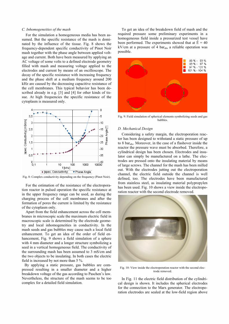
Apart from the field enhancement across the cell mem-branes in microscopic scale the maximum electric field in macroscopic scale is determined by the electrode geome-try and local inhomogeneities in conductivity. In the mash seeds and gas bubbles may cause such a local field enhancement. To get an idea of the order of field en-hancement, Fig. 9 shows a field simulation of a sphere with 4 mm diameter and a longer structure symbolizing a seed in a vertical homogeneous field. The conductivity of the surrounding mash has been assumed to 3 mS/cm and the two objects to be insulating. In both cases the electric field is increased by not more than 5 %.
By applying a static pressure, gas bubbles are com-pressed resulting in a smaller diameter and a higher breakdown voltage of the gas according to Paschen’s law. Nevertheless, the structure of the mash seems to be too complex for a detailed field simulation.
To get an idea of the breakdown field of mash and the required pressure some preliminary experiments in a homogeneous field inside a pressurized test vessel have been performed. The experiments showed that at Ê = 40 kV/cm at a pressure of 4 barabs a reliable operation was possible.
Fig. 9: Field simulation of spherical elements symbolizing seeds and gas bubbles.
D. Mechanical Design Considering a safety margin, the electroporation reac-
tor has been designed to withstand a static pressure of up to 8 barabs. Moreover, in the case of a flashover inside the reactor the pressure wave must be absorbed. Therefore, a cylindrical design has been chosen. Electrodes and insu-lator can simply be manufactured on a lathe. The elec-trodes are pressed onto the insulating material by means of large screws. The channel for the mash has been milled out. With the electrodes jutting out the electroporation channel, the electric field outside the channel is well defined, too. The electrodes have been manufactured from stainless steel, as insulating material polypropylen has been used. Fig. 10 shows a view inside the electropo-ration reactor with the second electrode removed.
Fig. 10: View inside the electroporation reactor with the second elec-trode removed.
In Fig. 11 the electric field distribution of the cylindri-
cal design is shown. It includes the spherical electrodes for the connection to the Marx generator. The electropo-ration electrodes are sealed at the low-field region above
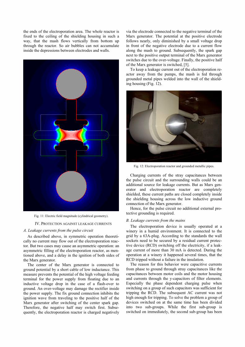
the ends of the electroporation area. The whole reactor is fixed to the ceiling of the shielding housing in such a way, that the mash flows vertically from bottom up through the reactor. So air bubbles can not accumulate inside the depressions between electrodes and walls.
Fig. 11: Electric field magnitude (cylindrical geometry).
IV. PROTECTION AGAINST LEAKAGE CURRENTS
A. Leakage currents from the pulse circuit As described above, in symmetric operation theoreti-
cally no current may flow out of the electroporation reac-tor. But two cases may cause an asymmetric operation: an asymmetric filling of the electroporation reactor, as men-tioned above, and a delay in the ignition of both sides of the Marx generator.
The center of the Marx generator is connected to ground potential by a short cable of low inductance. This measure prevents the potential of the high voltage feeding terminal for the power supply from floating due to an inductive voltage drop in the case of a flash-over to ground. An over-voltage may damage the rectifier inside the power supply. The fix ground connection inhibits the ignition wave from traveling to the positive half of the Marx generator after switching of the center spark gap. Therefore, the negative half may switch first. Subse-quently, the electroporation reactor is charged negatively
via the electrode connected to the negative terminal of the Marx generator. The potential at the positive electrode follows nearly, only diminished by a small voltage drop in front of the negative electrode due to a current flow along the mash to ground. Subsequently, the spark gap next to the positive output terminal of the Marx generator switches due to the over-voltage. Finally, the positive half of the Marx generator is switched, [5].
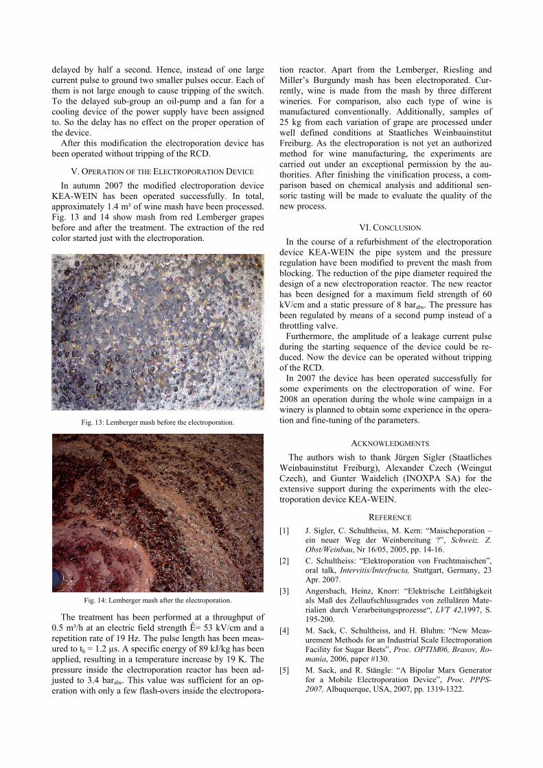
To keep a leakage current out of the electroporation re-actor away from the pumps, the mash is fed through grounded metal pipes welded into the wall of the shield-ing housing (Fig. 12).
Fig. 12: Electroporation reactor and grounded metallic pipes. Charging currents of the stray capacitances between
the pulse circuit and the surrounding walls could be an additional source for leakage currents. But as Marx gen-erator and electroporation reactor are completely shielded, these current paths are closed completely inside the shielding housing across the low inductive ground connection of the Marx generator.
Hence, for the pulse circuit no additional external pro-tective grounding is required.
B. Leakage currents from the mains The electroporation device is usually operated at a
winery in a humid environment. It is connected to the grid by a 63A-plug. According to the standards the wall sockets need to be secured by a residual current protec-tive device (RCD) switching off the electricity, if a leak-age current of more than 30 mA is detected. During the operation at a winery it happened several times, that the RCD tripped without a failure in the insulation.
The reason for this behavior were capacitive currents from phase to ground through stray capacitances like the capacitances between motor coils and the motor housing and currents through the y-capacitors of filter elements. Especially the phase dependent charging pulse when switching on a group of such capacitors was sufficient for tripping the RCD. The subsequent AC current was not high enough for tripping. To solve the problem a group of devices switched on at the same time has been divided into two sub-groups. While the first sub-group is switched on immediately, the second sub-group has been
delayed by half a second. Hence, instead of one large current pulse to ground two smaller pulses occur. Each of them is not large enough to cause tripping of the switch. To the delayed sub-group an oil-pump and a fan for a cooling device of the power supply have been assigned to. So the delay has no effect on the proper operation of the device.
After this modification the electroporation device has been operated without tripping of the RCD.
V. OPERATION OF THE ELECTROPORATION DEVICE In autumn 2007 the modified electroporation device
KEA-WEIN has been operated successfully. In total, approximately 1.4 m³ of wine mash have been processed. Fig. 13 and 14 show mash from red Lemberger grapes before and after the treatment. The extraction of the red color started just with the electroporation.
Fig. 13: Lemberger mash before the electroporation.
Fig. 14: Lemberger mash after the electroporation.
The treatment has been performed at a throughput of 0.5 m³/h at an electric field strength Ê= 53 kV/cm and a repetition rate of 19 Hz. The pulse length has been meas-ured to th = 1.2 µs. A specific energy of 89 kJ/kg has been applied, resulting in a temperature increase by 19 K. The pressure inside the electroporation reactor has been ad-justed to 3.4 barabs. This value was sufficient for an op-eration with only a few flash-overs inside the electropora-
tion reactor. Apart from the Lemberger, Riesling and Miller’s Burgundy mash has been electroporated. Cur-rently, wine is made from the mash by three different wineries. For comparison, also each type of wine is manufactured conventionally. Additionally, samples of 25 kg from each variation of grape are processed under well defined conditions at Staatliches Weinbauinstitut Freiburg. As the electroporation is not yet an authorized method for wine manufacturing, the experiments are carried out under an exceptional permission by the au-thorities. After finishing the vinification process, a com-parison based on chemical analysis and additional sen-soric tasting will be made to evaluate the quality of the new process.
VI. CONCLUSION In the course of a refurbishment of the electroporation
device KEA-WEIN the pipe system and the pressure regulation have been modified to prevent the mash from blocking. The reduction of the pipe diameter required the design of a new electroporation reactor. The new reactor has been designed for a maximum field strength of 60 kV/cm and a static pressure of 8 barabs. The pressure has been regulated by means of a second pump instead of a throttling valve.
Furthermore, the amplitude of a leakage current pulse during the starting sequence of the device could be re-duced. Now the device can be operated without tripping of the RCD.
In 2007 the device has been operated successfully for some experiments on the electroporation of wine. For 2008 an operation during the whole wine campaign in a winery is planned to obtain some experience in the opera-tion and fine-tuning of the parameters.
ACKNOWLEDGMENTS The authors wish to thank Jürgen Sigler (Staatliches
Weinbauinstitut Freiburg), Alexander Czech (Weingut Czech), and Gunter Waidelich (INOXPA SA) for the extensive support during the experiments with the elec-troporation device KEA-WEIN.
REFERENCE [1] J. Sigler, C. Schultheiss, M. Kern: “Maischeporation –
ein neuer Weg der Weinbereitung ?”, Schweiz. Z. Obst/Weinbau, Nr 16/05, 2005, pp. 14-16.
[2] C. Schultheiss: “Elektroporation von Fruchtmaischen”, oral talk, Intervitis/Interfructa, Stuttgart, Germany, 23 Apr. 2007.
[3] Angersbach, Heinz, Knorr: “Elektrische Leitfähigkeit als Maß des Zellaufschlussgrades von zellulären Mate-rialien durch Verarbeitungsprozesse“, LVT 42,1997, S. 195-200.
[4] M. Sack, C. Schultheiss, and H. Bluhm: “New Meas-urement Methods for an Industrial Scale Electroporation Facility for Sugar Beets”, Proc. OPTIM06, Brasov, Ro-mania, 2006, paper #130.
[5] M. Sack, and R. Stängle: “A Bipolar Marx Generator for a Mobile Electroporation Device”, Proc. PPPS-2007, Albuquerque, USA, 2007, pp. 1319-1322.


![Analyse DAX 2016 07 12.pptx.ppt [Kompatibilit tsmodus]) · Gap / Gap-Closing / Opening-Gap / Exhausting-Gap / Eröffnungs (Opening) -Gap Die Unterstützungslinie gehört zu den Chartformationen,](https://static.fdocuments.net/doc/165x107/5ca9096788c99371398be22b/analyse-dax-2016-07-12pptxppt-kompatibilit-tsmodus-gap-gap-closing-.jpg)
