Optimale Sicherheit - homatec.de · Core drill 116 Coupling bar 30 Curved machining guide 78 Cutter...
169
Transcript of Optimale Sicherheit - homatec.de · Core drill 116 Coupling bar 30 Curved machining guide 78 Cutter...


Optimal arbeitenOptimale Sicherheit
Travail optimalSécurité optimale
Optimal workingOptimal safety
2014

2
Technique de Sécurité Aigner pour le travail professionnel du boisLes dispositifs de sécurité et de travail Aigner se sont révélés indispensables depuis des années dans le travail complexe du bois. Partout où préci- sion, rendement, sécurité et rentabilité sont requis au plus haut niveau, les appareils Aigner trouvent leur place tout naturellement dans le processus de fabrication. La technique de sécurité Aigner s'est toujours fixé comme but de s'attaquer aux travaux spéciaux ou problématiques, d'en faire l'analyse et de trouver de nouvelles idées pour l'élaboration et la mise au point d'accessoires efficaces.
La plus haute exigence pour la qualité des maté -
r i aux et le soin de l'usinage jouent ici un rôle pri -mor dial et sont devenus des critères de fabri-cation.
Les dispositifs de travail et de sécurité Aigner sont d'un emploi universel et d'un montage ra-pide. Ils sont légers et faciles à manier, irrempla-çables dans leur fonction et se distinguent par une ex trême longévité.
Protection optimale et haute qualité de travail – objectifs premiers dans la conception des dispositifs de travail et de sécurité Aigner.
Ce catalogue donne une vue d'ensemble com-plète de la gamme des produits Aigner et pré - s ente leurs caractéristiques principales de cons-truction et d'utilisation.
Aigner safety technics for professional wood workingAigner safety and working units have been fully approved over the years where the complex shap-ing of timber is carried out. Woodworking proces-ses require a combination of accuracy, perfor-mance, safety and efficiency unthinkable without Aigner equipment.
Aigner safety technicians are well known for their ability to investigate complex tasks analyse the problems and invent what are basically new pro-ducts to improve both production and safety. The standards of quality of the materials and the accu-racy of the machining and surface treatments re-ceive the highest priority in the production of the
equipment. Aigner safety and working units are universal in their application across a wide range of wood working and other machinery. Ease and speed of mounting the equipment onto the ma-chine, combined with the value and long service life make the Aigner equipment excellent value for money.
Maximum operator protection, the ease and accuracy of fine adjustment and the quality of the finished work has always been the targets of the Aigner organisation.
This catalogue represents the full production range of standard Aigner equipment and intro- duces the more important aspects of the con-struction and application of this equipment.
Aigner-Sicherheitstechnik für die professionelle HolzbearbeitungAigner-Sicherheits- und Arbeitsvorrichtungen haben sich seit Jahren in der anspruchsvollen Be-arbeitung von Holz hervorragend bewährt. Überall dort, wo Präzision, Leistung, Sicherheit und Wirt-schaftlichkeit in perfektem Zusammenspiel gefor-dert werden, sind Aigner-Geräte aus dem Arbeits-prozeß nicht mehr wegzudenken.
Aigner-Sicherheitstechnik ist bekannt dafür, sich der speziellen „Problemarbeiten“ anzunehmen, sie zu analysieren und neue Ideen zu entwickeln als Grundlage für die Konstruktion sinnvollen Zube hörs. Höchste Anforderungen an Material-
qualität und eine sorgfältige Weiterverarbeitung spielen dabei eine wichtige Rolle und setzen Maß-stäbe für die Fertigung. Aigner-Sicherheits- und Arbeitsvorrichtungen sind universell einsetzbar und schnell zu montieren. Sie sind leicht und be-quem zu handhaben, un über trof fen in ihrem Nutzen und zeichnen sich durch lange Lebensdauer aus.
Optimaler Arbeitsschutz und hohe Arbeitsqualität – Begriffe, die als Zielsetzung bei der Entwicklung der AignerSicherheits und Arbeitsvorrichtungen im Vordergrund stehen.
Dieser Katalog gibt einen Überblick über die ge -samte Aigner-Produktpalette und stellt ihre wich tig sten Konstruktions- und Anwendungs-merkmale vor.

14 106
140
156
20 64
116 136 138
150 152 154
3
Neu New Nouveau

10
26
36
50
60
12
28
38 42
44
40
52
66
16
30
54
68
18
32
46
56
70
24
34
48
58 62
64 72
22
4
D ProduktübersichtGB Table of productsF Vue d'ensemble des articles

94
104
118
132
164
96
108
120
128
126
144
98
110
122
148
100
112
124
134
158
102
114
130
160
9288 908684
76 78 80 8274
5

6
D Alphabetischer Produktindex
A Seite Abplattprofi 58 Absaugeinheit 82 Abstandhalter 48 Abweiser 132 Aufhänger 28 B Befestigungsadapter 18, 20 Befestigungsklötze 90 Befestigungsplatten 68 Befestigungsschiene 10, 12, 14 Befestigungsschiene V 16 Befestigungssäule 150 Befestigungswinkel 22 Bohrsenker 116 Bogenfräsanschlag 78 Bogenfräsmaster 76 Bündix 56 C Centrex 84 Contermax 60 D Dickenanschlag 74 Distanzhalter 70 Distanzhülsen 72 Distanzstück 86 Distometer 160 Doppelrolle 98 Druckbacken 108 Druckmodul 96 Druckschuh 100 E Einzelrolle 98 F Fräsbock 80 Fräsbock E 52 Furnierset 140 Führungsaufnahme 104 Führungsgleiter 104 Führungsleiste 154 Führungsrollen 102 Führungssatz 124 Füllstab 46 G Glasleister 62, 64 Gleitschuh 100
H Seite Halbrundschuh 104 Halbrundschuh V 104 Haltebrücke 90 Halteplatte 88 Hilfsanschlag 110 I Integralanschlag 38, 40, 42, 44
K Kantix 54 Klemmer 68 Klemmschuh 66 Kombianschlag 112 Kreisfix 36 M Messtaster 164 Montageplatte 72 Montagewinkel 72 Mutter 22 P Profileinsteller 158 Q Quickly 114 S Sägeboy 134, 136 Schiebestock 126 Schwenkbrücke 94 Schwenkklötze 92 Segmenter 124 Sicherheitsrolle 106 Spannlade 34 Spannplus 138 Spitzenset 116 T Tischverlängerung 24, 26 Tragarm 156 Tragplatte 152 Tragschiene 50 Tragschiene 80 Trenntop 128
U Universalauflage 118, 120, 122
V Seite Varioanschlag 32 Vectrafix 148 Vectral 144 Verbindungssteg 30 Viererrolle 100 Z Zinkenexakt 130

7
GB Alphabetic Index of products
A Page Angle bracket 22 Auxiliary fence 110 B BowmouldMaster 76 C Centrex 84 CirQuick 36 Clamp 68 Clamp strip 34 Clamping shoe 66 Clip 28 Contermax 60 Combifence 112 Core drill 116 Coupling bar 30 Curved machining guide 78 Cutter frame E 52 Cutter frame 80 D Deflector 132 Double wheel 98 Distometer 160 E Exhaust unit 82 Extension arm 156 F Filling bar 46 Flatserver 58 Flushfix 56 G Glassledger 62, 64 Guide set 124 Guide support 104 Guiding ledge 154 Guide wheels 102 H Hinged bridge 94 I Integral fence 38, 40, 42, 44
K Page Kantix 54 M Measuring tracer 164 Mortiseboy 130 Mounting adapter 18, 20 Mounting angle 72 Mounting blocks 90 Mounting plate 72 Mounting Post 150 Mounting plates 68 Mounting rail 10, 12, 14 Mounting rail V 16 N Nut 22 P Pressure jaws 108 Pressure module 96 Pressure shield 104 Pressure shield V 104 Pressure shoe 100 Profile adjuster 158 Protecting wheel 106 Push stick 126 Q Quad wheel 100 Quickly 114 S Sawboy 134, 136 Segmenter 124 Single wheel 98 Slide shoe 100 Sliding guide 104 Spacer 70 Spacer block 86 Spacer sleeves 72 Spanplus 138 Split-top 128 Spreader 48 Support plate 88 Supporting bridge 90 Supporting plate 152 Supporting rail 50 Supporting rail 80 Swivel blocks 92
T Page Table extension 24, 26 Thickness stop 74 Tip set 116 U Universal support 118, 120, 122 V Variostop 32 Vectrafix 148 Vectral 144 Veneer unit 140

8
F Index alphabétique d’article
A Page Adaptateur de fixation 18, 20 Affleurfixe 56 Ajusteur à profiler 158 Appui universel 118, 120, 122 Attache 68 B Barre de raccordement 30 Barre de treillis 46 Barre-Guide 154 Blocs de fixation 90 Blocs pivotants 92 Bras-Support 156 Butée d’épaisseur 74 Butée combinée 112 Butée Intégrale 38, 40, 42, 44 C Chantournix 76 Centrex 84 Chevalet de fraisage E 52 Chevalet de fraisage 80 Colonne de fixation 150 Contermax 60 Crochet de rangement 28 D Déflecteur 132 Distanceur 70 Distomètre 160 Douilles d’écartement 72 E Ecarteur 48 Écrou 22 Équerre de fixation 22 Équerre de montage 72 F Foret-Fraisoir 116 Fraise-Cercle 36 G Galet de Sécurité 106 Galet-Double 98 Galets-Guides 102 Galet-Simple 98 Galet-Quadruple 100 Guide auxiliaire 110 Guide de glissement 104 J Jeu de guides 124 Joues de pression 108
K Page Kantix 54 L Listonvitre 62, 64 Logement de guidage 104 Lunette-Guide 78 M Module-Presseur 96 N Nécessaire à pointes 116 P Palpeur 164 Patin Demi-Rond 104 Patin Demi-Rond V 104 Patin-Guide 100 Patin-Presseur 100 Pièce intercalaire 86 Pince de serrage 66 Plaques de fixation 68 Plaque de montage 72 Plaque d’appui 88Plaque-Support 152 Pont Basculant 94 Pont-Support 90 Poussoir 126 Précis-Queue 130 Pressplus 138 Pro-Plate-Bande 58 Q Quickly 114 R Rail de fixation 10, 12, 14 Rail de fixation V 16 Rail de support 50 Rail de support 80 Rallonge de table 24, 26 S Scie-boy 134, 136 Sécaplaque 140 Segmenteur 124 Serre-pièce 34 Système d’aspiration 82
T Page Top de Refend 128 V Varioguide 32 Vectral 144 Vectrafix 148

9
D Numerischer ProduktindexGB Numerical index of productsF Index numérique d’article
211 Seite Page 211 123 000 192 110211 141 000 196 112211 143 000 196 112 212 212 102 000 191 10212 103 000 191 10212 104 000 191 10212 105 000 191 10212 108 000 191 10212 112 000 191 12212 113 000 191 12212 114 000 191 12212 115 000 191 12212 135 000 191 14212 137 000 191 14212 138 000 191 14212 147 000 191 14212 148 000 191 14212 163 000 192 16212 164 000 192 16212 171 000 192 18212 173 000 192 18212 175 000 192 20212 182 000 172 22212 184 000 172 22212 187 000 172 22212 205 000 193 114212 206 000 192 116212 209 000 192 116212 212 000 192 24212 223 000 172 28212 226 000 172 30212 232 000 192 36212 262 000 192 66212 266 000 192 66212 273 000 192 68212 282 000 192 70212 291 000 172 72212 293 000 172 72212 295 000 172 72212 297 000 172 72212 298 000 172 72212 322 000 173 118212 323 000 173 120212 324 000 173 118212 325 000 173 120212 326 000 173 118212 327 000 173 120212 328 000 173 118212 329 000 173 120212 333 000 173 122212 335 000 173 122212 337 000 173 122
212 Seite Page 212 339 000 173 122212 342 000 173 118212 343 000 173 120212 344 000 173 118212 345 000 173 120212 346 000 173 118212 347 000 173 120212 348 000 173 118212 349 000 173 120212 353 000 173 122212 355 000 173 122212 357 000 173 122212 359 000 173 122212 362 000 173 118212 363 000 173 120212 364 000 173 118212 365 000 173 120212 366 000 173 118212 367 000 173 120212 368 000 173 118212 369 000 173 120212 373 000 173 122212 375 000 173 122212 377 000 173 122212 379 000 173 122 213 213 311 000 193 38213 313 000 193 38213 315 000 193 38213 317 000 193 38213 351 000 193 40213 353 000 193 40213 355 000 193 40213 357 000 193 40213 371 000 193 42213 373 000 193 42213 375 000 193 42213 377 000 193 42213 381 000 193 44213 383 000 193 44213 385 000 193 44213 387 000 193 44213 503 000 172 68213 505 000 193 50213 551 000 172 46213 552 000 172 48213 716 000 193 74 214 214 113 000 192 26214 114 000 192 26214 119 000 192 32214 263 000 192 52
214 Seite Page 214 264 000 192 54214 265 000 192 56214 267 000 192 58214 283 000 192 34214 287 000 193 60214 292 000 192 62214 293 000 192 64214 295 000 192 64214 327 000 192 82214 353 000 173 78214 354 000 173 78214 355 000 173 78214 356 000 173 78214 357 000 173 78214 358 000 173 78214 366 000 192 76214 368 000 192 80214 369 000 192 80214 373 000 173 78214 374 000 173 78214 375 000 173 78214 376 000 173 78214 377 000 173 78214 378 000 173 78214 383 000 192 76214 385 000 192 80214 389 000 193 80214 455 000 192 84214 462 --- 172 86214 462 250 172 86214 462 500 172 86214 463 000 172 88214 465 000 172 90214 466 000 172 90214 468 000 172 90214 469 000 172 92214 473 000 172 94214 474 000 172 94214 524 000 192 96214 524 920 192 104214 526 000 192 96214 531 000 192 98214 533 000 192 98214 535 000 192 100214 537 000 192 100214 539 000 192 100214 543 000 192 102214 545 000 192 102214 547 000 192 102214 552 000 192 104214 554 000 192 104214 558 000 192 104214 564 000 192 106214 572 000 192 108
216 Seite Page 216 133 000 193 124216 135 000 193 124216 136 000 191 126216 138 000 192 128216 149 000 192 130216 157 000 193 132216 162 000 192 134216 165 000 192 136216 167 000 192 136216 172 000 192 138216 174 000 192 138216 176 000 192 138216 182 000 192 140216 184 000 192 140216 186 000 192 140216 242 000 193 144216 246 000 193 144216 252 000 193 144216 286 000 193 144216 292 000 192 148216 294 000 192 148216 296 000 192 148216 414 000 192 150216 423 000 172 152216 434 000 162 154216 443 000 112 156 221 221 122 000 192 158221 123 000 192 158221 124 000 192 158221 125 000 192 158221 126 000 192 158221 127 000 192 158221 128 000 192 158 221 256 000 192 160221 263 000 172 164

IV V
IIIII
I
C
B
A
40
10
8 30
10
10
BefestigungsschieneDas universelle Grund element zur Aufnahme von AignerSicherheits und Arbeitsvorrichtungen.Die Aigner-Befestigungsschiene ist in 5 verschiedenen Längen für alle Tisch- größen geeignet. Sie dient der schnel- len und sicheren Befestigung von Sicherheits- und Arbeitsvor richtungen ohne Zuhilfenahme von Werkzeugen.
BefestigungsschieneLänge: 250 mmmit GebrauchsanleitungMounting raillength: 250 mmwith operating instructionsRail de fixationlongueur 250 mmavec notice d'utilisationArt. No. 212 102 000 191BefestigungsschieneLänge: 330 mmmit GebrauchsanleitungMounting raillength: 330 mmwith operating instructionsRail de fixation longueur 330 mmavec notice d'utilisationArt. No. 212 103 000 191BefestigungsschieneLänge: 430 mmmit GebrauchsanleitungMounting raillength: 430 mmwith operating instructionsRail de fixation longueur 430 mmavec notice d'utilisationArt. No. 212 104 000 191BefestigungsschieneLänge: 530 mmmit GebrauchsanleitungMounting raillength: 530 mmwith operating instructionsRail de fixation longueur 530 mmavec notice d'utilisationArt. No. 212 105 000 191BefestigungsschieneLänge: 830 mmmit GebrauchsanleitungMounting raillength: 830 mmwith operating instructionsRail de fixation longueur 830 mmavec notice d'utilisationArt. No. 212 108 000 191
Mounting railThe universal component to allow the mounting of Aigner safety and working units.The Aigner mounting rail is suitable for most table sizes and is available in 5 different lengths. The rails provide fast and safe means to mount safety and work-ing equipment on a wide range of woodworking equipment without the necessity of additional tools.
Rail de fixationElément de base uni versel pour la fixation des dispositifs de travail et de sécurité Aigner.Le Rail de fixation Aigner, dis- ponible en 5 longueurs, s'adapte à toutes les grandeurs de table. Il est utilisé pour la fixation sûre et rapide des dispositifs de travail et de sécurité, sans l'aide d'aucun outil.
IV
V
III
II
I A
A
A
A
A
B
B
B
B
B
C
C
C
C
C
250 195 100
330 250 150
430 350 200
530 450 300
830 750 300/300
IV
V
III
II
I A
A
A
A
A
B
B
B
B
B
C
C
C
C
C
250 195 100
330 250 150
430 350 200
530 450 300
830 750 300/300
IV
V
III
II
I A
A
A
A
A
B
B
B
B
B
C
C
C
C
C
250 195 100
330 250 150
430 350 200
530 450 300
830 750 300/300
Sondermaße auf Anfrage
Special size on request
Cotes spéciales sur demande
Indication : Autres versions p.12,14,16
Reference: Further versions p.12,14,16
Hinweis: Weitere Ausführungen S.12,14,16

10
11 12
1 2
3
6
4
5
87
9
11
Befestigungsschienen an der Tischfräsmaschine.
An der Bedienerseite sind die Schie-nen Art. No. 212 108 000 191 montiert.
Befestigungsschienen an der Kantenschleif-
maschine.
Befestigungsschienen an der Langlochbohr-
maschine.
Befestigungsschienen an der Bandsägemaschine.
Befestigungsschiene an der Kanten anleimmaschine
– Aufgabeseite.
Befestigungsschienen an der Gehrungskreissäge.
Befestigungsschienen an der Kopierfräse.
2
3
5
7
11
4
6
8
12
9 10
Mounting rails attached to the spindle milling
machine. The rails Art. No. 212 108 000 192 are attached to the tending side.
Mounting rails attached to an edge sanding
machine.
Mounting rails attached to a dowel boring
machine.
Mounting rails attached to a band saw table.
Mounting rail attached to the infeed end of an edge banding
machine.
Mounting rails attached to a mitre sawing machine.
Mounting rails attached to a copy-milling machine.
Rail de fixation monté sur la table de toupie.
Côté opérateur est monté le Rail art. n° 212 108 000 191
Rail de fixation sur la ponceuse de chants.
Rail de fixation sur la perceuse longitudinale.
Rail de fixation sur la scie à ruban.
Rail de fixation sur la pla- queuse de chants, côté entrée.
Rail de fixation sur la scie circulaire à onglet.
Rail de fixation sur la toupie à copier.
1 2
10
11 12
3
5
7
4
6
8
9
1 2
3
5
7
4
6
8
9 10
11 12
1

IVIII
II
I
B
A
40
10
8
30
10
12
BefestigungsschieneDas universelle Grund element für Sonderfälle.Diese Befestigungsschiene ist erforderlich, wenn auf der ganzen Länge der Schiene Sicherheits- und Arbeitsvor richtungen angebracht werden sollen.
BefestigungsschieneLänge: 230 mmmit GebrauchsanleitungMounting raillength: 230 mmwith operating instructionsRail de fixationlongueur 230 mmavec notice d'utilisationArt. No. 212 112 000 191BefestigungsschieneLänge: 330 mmmit GebrauchsanleitungMounting raillength: 330 mmwith operating instructionsRail de fixation longueur 330 mmavec notice d'utilisationArt. No. 212 113 000 191BefestigungsschieneLänge: 430 mmmit GebrauchsanleitungMounting raillength: 430 mmwith operating instructionsRail de fixation longueur 430 mmavec notice d'utilisationArt. No. 212 114 000 191BefestigungsschieneLänge: 530 mmmit GebrauchsanleitungMounting raillength: 530 mmwith operating instructionsRail de fixation longueur 530 mmavec notice d'utilisationArt. No. 212 115 000 191
Mounting railThe universal component for particular cases.This rail type is required when safety and working units have to be mounted over the whole rail length.
Rail de fixationElément de base universel pour cas spéciaux.Ce Rail de fixation est nécessaire lorsque l'on doit y monter sur toute sa longueur des dispositifs de travail ou de sécurité.
IV
III
II
I A
A
A
A
B
B
B
B
230 100
330 150
430 200
530 300
IV
III
II
I A
A
A
A
B
B
B
B
230 100
330 150
430 200
530 300
Special size on request
Sondermaße auf Anfrage
IV
III
II
I A
A
A
A
B
B
B
B
230 100
330 150
430 200
530 300
Cotes spéciales sur demande
Indication : Autres versions p.10,14,16
Reference: Further versions p.10,14,16
Hinweis: Weitere Ausführungen S.10,14,16

1 2
5
6
3 4
7
13
Rail de fixation monté sur la raboteuse-dégauchis-
seuse.
Rail de fixation sur la gauche d'une scie à lame ascendante.
Rail de fixation sur la droite d'une scie à lame ascendante.
Rail de fixation sur une corroy-euse.
Rail de fixation sur une ma- chine automatique de finition
des chants.
Rail de fixation monté sur la table de toupie.
Côté opérateur est monté le Rail art. n° 212 108 000 191
Mounting rails attached to a surface planing
machine.
Mounting rail attached to the left of a sub-bench saw.
Mounting rail attached to the right of a sub-bench saw.
Mounting rail attached to a four side planer.
Mounting rail attached to an edge profiler.
Mounting rails attached to the spindle milling
machine. The rail Art. No. 212 108 000 191 is attached to the tending side.
Befestigungsschienen an der Abrichthobel-
maschine.
Befestigungsschiene links an der U ntertisch säge.
Befestigungsschiene rechts an der Untertischsäge.
Befestigungsschiene an der Vierseiten hobel maschine.
Befestigungsschiene am Kantenbearbeitungs automat.
Befestigungsschienen an der Tischfräsmaschine. An der
Bedienerseite ist die Schiene Art. No. 212 108 000 191 montiert.
1 2
5
4
6
7
1
3
5
2
4
6
7
1
3
5
2
4
6
7
3

A
B
C
830
14
Rail de fixationElément de base universel pour toupies ayant un appui extensible apte à recevoir des dispositifs de sécurité et de travail.Le Rail de fixation se monte et se fixe rapidement sur l’appui extensible.
80 30
80 40
80 50
100 40
100 50
Blocage du Rail de fixation à l’aide d’une clé mâle
coudée 6 pans.
Befestigungsschiene Das universelle Grundelement für Tischfräsmaschinen mit ausziehbarer Auflage zur Aufnahme von Sicherheits und Arbeitsvorrichtungen.Die Befestigungsschiene lässt sich schnell auf die ausziehbare Auflage aufstecken und festklemmen.
80 30
80 40
80 50
100 40
100 50
Weitere Abmessungen auf Anfrage
Festklemmen der Befestigungs-schiene mit Sechskant-Winkel-
schraubendreher.
A
A
A
A
A
B
B
B
B
B
C
Befestigungsschiene passend für A 80 / B 30 mit GebrauchsanleitungMounting rail suitable for A 80 / B 30 with operating instructionRail de fixation pour A 80 / B 30 avec notice d’utilisationArt. No. 212 135 000 191Befestigungsschiene passend für A 80 / B 40 mit GebrauchsanleitungMounting rail suitable for A 80 / B 40 with operating instructionRail de fixation pour A 80 / B 40 avec notice d’utilisationArt. No. 212 137 000 191Befestigungsschiene passend für A 80 / B 50 mit GebrauchsanleitungMounting rail suitable for A 80 / B 50 with operating instructionRail de fixation pour A 80 / B 50 avec notice d’utilisationArt. No. 212 138 000 191Befestigungsschiene passend für A 100 / B 40 mit GebrauchsanleitungMounting rail suitable for A 100 / B 40 with operating instructionRail de fixation pour A 100 / B 40 avec notice d’utilisationArt. No. 212 147 000 191Befestigungsschiene passend für A 100 / B 50 mit GebrauchsanleitungMounting rail suitable for A 100 / B 50 with operating instructionnRail de fixation pour A 100 / B 50 avec notice d’utilisation
Art. No. 212 148 000 191
Indication : Autres versions p.10,12,16
Mounting railUniversal element for use on spindle milling machines with extractable support that can be used to mount safety and working units.The mounting rail may be rapidly slipped on and clamped to the extractable support.
80 30
80 40
80 50
100 40
100 50
Clamping the mounting rail with Allen key. C
A
A
A
A
A
B
B
B
B
B
Reference: Further versions p.10,12,16
Hinweis: Weitere Ausführungen S.10,12,16
C
A B
A B
A B
A B
A B
Special size on request
Autres dimensions sur demande

1
2 3
15
Befestigungsschiene an der ausziehbaren Auflage.
Ausziehbare Auflage mit Befestigungsschiene einge-
schoben.
Ausziehbare Auflage mit Befestigungsschiene ausge-
zogen.
1
2
3
Rail de fixation sur l’appui extensible.
Appui extensible rentré avec Rail de fixation.
Appui extensible sorti avec Rail de fixation.
Mounting rail attached to the extractable support.
Extractable support with mounting rail pushed in.
Extractable support with mounting rail drawn out.
1
2
3
1
2
3

I
II
A
B
375
525
16
Rail de fixation VÉlément de base universel pour toupie à table cou lissante intégrée pour la fixation de dispositifs de travail et de sé curité.Le Rail de fixation V peut se régler en continu et sans outil.
Rail de fixation V pour le côté droit de la machine.
Rail de fixation V pour le côté gauche de la machine.
Befestigungsschiene VDas universelle Grundele ment für Tischfräsmaschinen mit integriertem Schiebetisch zur Aufnahme von Sicherheits und Arbeitsvorrichtungen.Die Befestigungsschiene V kann stu fen- los und ohne Werkzeug verstellt werden.
Befestigungsschiene Vfür die rechte Maschinenseite.
Befestigungsschiene V für die linke Maschinenseite.
Befestigungsschienen V zusammengeschoben.
Befestigungsschienen V ausgezogen.
Befestigungsschiene V rechts, mit Befestigungsschrauben, Bohrschablone und Gebrauchsan-leitungMounting rail Vright-hand, with fastening screws, bore template and operating in-structionsRail de fixation V à droite, avec vis de fixation, gabarit de perçage et notice d'utilisationArt. No. 212 163 000 192Befestigungsschiene V links, mit Befestigungsschrauben, Bohrschablone und Gebrauchsan-leitungMounting rail Vleft-hand, with fastening screws, bore template and operating in-structionsRail de fixation V à gauche, avec vis de fixation, gaba-rit de perçage et notice d'utilisationArt. No. 212 164 000 192
Mounting rail VThis basic universal element for use on spindle milling machines fitted with sliding tables. The mounting rails can be used to mount safety and working units.Mounting rail V is easily ad jus t able without any additional tool.
Mounting rail Vfor the righthand side of the machine.
Mounting rail Vfor the lefthand side of the machine.
Mounting rails V collapsed.
Mounting rails V extended.
I
II
A
B
I
II
Rail de fixation V rentré.
Rail de fixation V sorti.
A
B
I
II
Indication : Autres versions p.10,12,14 Rallonge de table p.24, 26 Crochet de rangement p.28
Reference: Further versions p.10,12,14 Table extension p.24,26 Clip p.28
Hinweis: Weitere Ausführungen S.10,12,14 Tischverlängerung S.24,26 Aufhänger S.28
B
A

1 2
43
5
17
Befestigungsschiene V zusam-mengeschoben an der Tisch-
fräsmaschine links.
Befestigungsschiene V zusam-mengeschoben an der Tisch-
fräsmaschine rechts.
Befestigungsschiene V ausge-zogen an der Tischfräsmaschi-
ne links.
Befestigungsschiene V ausge-zogen an der Tischfräsmaschi-
ne rechts.
An den Befestigungsschienen V angebrachte Tischverlängerun-
gen zum sicheren Bearbeiten langer Werkstücke.
1
2
3
4
5
Rail de fixation V rentré et fixé sur le côté gauche de la toupie.
Rail de fixation V rentré et fixé sur le côté droit de la toupie.
Rail de fixation V sorti et fixé sur le côté gauche de la toupie.
Rail de fixation V sorti et fixé sur le côté droit de la toupie.
Rallonges de table montées sur les Rails de fixation V pour
tra vailler plus sûrement les pièces lon gues.
1
2
3
4
5
Mounting rail V closed and fixed on the left side of the
spin dle milling machine.
Mounting rail V closed and fixed on the right side of the
spin dle milling machine.
Mounting rail V extended on the left side of the machine.
Mounting rail V extended on the right side of the machine.
Table extensions mounted on the mounting rails V in use with
long workpieces.
1
2
3
4
5

A B
C
E
D
I
II
min
. 10
m
ax. 4
017
2
60
172
220
18
Befestigungs- adapterGrundelement zur Aufnahme von Sicherheits und Arbeitsvorrichtungen an Maschinen mit Rundstangenführung.Der Befestigungsadapter paßt für Rundstangenführungen von ø 24 bis ø 55 mm, läßt sich schnell und ohne Werkzeug anbringen und ab-nehmen.
Die Oberfläche ist durch Eloxierung vergütet.
Für Abstand Tischkante bis Mitte Rundstange von max. 60 mm.
Befestigungs- adapterFür Abstand Tischkante bis Mitte Rundstange über 60 mm.
Rundstange ø min. 24 mm
Rundstange ø max. 55 mm
Verstellbereich
Schenkellänge entspre-chend kürzen, wenn der
Abstand Tischkante bis Mitte Rundstange unter 60 mm bzw. unter 220 mm ist.
Mounting adapter Universal component to allow safety and working units to be mounted on machines provided with round guide bars.The mounting adapter is suitable for round guide bars from ø 24 to ø 55 mm. Fixing and detaching the adapter is a rapid operation without using any tool.
The surface is hardened by anodic treatment.
Fits for distance table edge – axis of round bar up to 60 mm.
Mounting adapter Fits for distance table edge – axis of round bar more than 60 mm.
Round bar ø min. 24 mm
Round bar ø max. 55 mm
Adjusting range
If the distance between table edge and bar axis
is less than 60 mm or 220 mm respectively, the flange should be shortened.
A
B
A
B
C
D E
Befestigungsadapter passend für Abstand Tischkante bis Mitte Rundstange von max. 60 mm mit GebrauchsanleitungMounting adapter fits for a distance table edge – bar axis up to 60 mm with operating instructionsAdaptateur de fixation Convient pour distance max. de 60 mm entre bord de table et centre de la barre ronde avec notice d'utilisation
Art. No. 212 171 000 192Befestigungsadapter passend für Abstand Tischkante bis Mitte Rundstange über 60 mm mit GebrauchsanleitungMounting adapter fits for a distance table edge – bar axis more than 60 mm with operating instructionsAdaptateur de fixation Convient pour distance de plus de 60 mm entre bord de table et centre de la barre ronde avec notice d'utilisation
Art. No. 212 173 000 192
Adaptateur de fixationElément de base pour la fixation de dispositifs de travail et de sécurité sur les machines avec barre de guidage ronde.L’adaptateur de fixation convient pour les barres de guidage rondes de ø 24 à ø 55 mm, il se monte et s’enlève sans outil.
La surface est traitée par anodisation.
Pour une distance de 60 mm maximum entre le bord de table et le centre de la barre ronde.
Adaptateur de fixationPour une distance de plus de 60 mm entre le bord de table et le centre de la barre ronde.
Barre ronde ø min. 24 mm
Barre ronde ø max. 55 mm
Etendue de réglage
Raccourcir la longueur du bras selon que la
distance entre bord de table et centre de la barre est inférieure à 60 mm ou inférieure à 220 mm.
A
B
C
D E
C
D E
I II
I II
I II
Indication : Autres versions p.20 Rallonge de table p.24,26 Crochet de rangement p.28
Reference: Further version p.20 Table extension p.24,26 Clip p.28
Hinweis: Weitere Ausführung S.20 Tischverlängerung S.24,26 Aufhänger S.28

1
2
43
19
Befestigungsadapter I an der Rundstangenführung einer
Maschine.
Befestigungsadapter II an der Rundstangenführung einer
Maschine.
An den Befestigungs- adaptern angebrachte
Tischverlängerungen zum sicheren Bearbeiten langer Werkstücke.
Adaptateur de fixation I sur la barre de guidage ronde d’une
machine.
Adaptateur de fixation II sur la barre de guidage ronde d’une
machine.
Rallonges de table sur des adaptateurs de fixa-
tion pour travailler plus sûrement les pièces longues.
1
2
3 4
1
2
3 4
Mounting adapter I attached to the round guide bar of a
machine.
Mounting adapter II attached to the round guide bar of a
machine.
Table extensions attached to the mounting adapters
for safe machining of long work- pieces.
1
2
3 4

A
min
. 14
m
ax. 6
0
min
. 12
m
ax. 4
010
8
min. 18 max. 51
B
20
BefestigungsadapterGrundelement zur Aufnahme von Sicherheits und Arbeits vorrichtungen an Maschinen mit Rechteck oder Profil führung.Der Befestigungsadapter lässt sich schnell und ohne Werkzeug anbringen und abnehmen.
Die Oberfläche ist durch Eloxierung vergütet.
Verstellbereiche
Adaptateur de fixationElément de base pour la fixation de dispositifs de travail et de sécurité sur les machines avec barres de guidage rectangulaires ou profilées.L’adaptateur de fixation se monte ou s’enlève rapidement et sans outil. La surface est traitée par anodisation.
Zone de réglage.
A B
Befestigungsadaptermit Sechskant-Winkelschrauben-dreher und GebrauchsanleitungMounting adapterwith Allen key and operating instructions Adaptateur de fixationavec clé mâle coudée six pans et notice d’utilisationArt. No. 212 175 000 192
Mounting adapterUniversal component to allow safety and working units to be mounted on machines with guide bars of rectangular or profiled section. Fixing and detaching the mounting adapter is a rapid operation without using any tool.
The surface is hardened by anodic treatment.
Adjusting rangesA B
Indication : Autres versions p.18 Rallonge de table p.24,26 Crochet de rangement p.28
Reference: Further versions p.18 Table extension p.24,26 Clip p.28
Hinweis: Weitere Ausführungen S.18 Tischverlängerung S.24,26 Aufhänger S.28
A B

1
2
3
21
Befestigungsadapter an Rechteck-Stangenführun-
gen von Maschinen.
Befestigungsadapter an der Profil-Stangenführung einer
Maschine.
Adaptateur de fixation sur une barre de guidage
rectangulaire.
Adaptateur de fixation sur une barre de guidage profilée.
1 2
3
1 2
3
Mounting adapter attached to a rectangular
guide bar of machines.
Mounting adapter attached to a profiled guide bar of a
machine.
1 2
3

A
B
C
I
II
III
1,5
4,5
D30
12,8
50
M 10
4
22
Angle bracket A support unit enabling pressure modules to be mounted on the machine table.The angle bracket can be fastened onto the machine table by means of set screws or by screws and special nuts in the table slots.
Angle bracket Enlarged field of use, e.g. on a sliding table having a Tslot.
NutFor attaching the angle bracket to the table where Tslots are provided.
Angle bracket screwed in the T-slot by means of
socket head cap screws and nuts.
Angle bracket fastened on a machine table by means of
socket head cap screws.
Nut for T-slots. Customised nuts upon request.
Befestigungs- winkelDas Grundelement zur Aufnahme von Druck modulen auf Tischflächen.Der Befestigungswinkel kann auf Tisch flächen oder mit den Muttern in T-Nuten mit Zylinderschrauben be fes tigt werden.
Befestigungs- winkelMit erweiterter Einsetzmöglichkeit z.B. Schiebetisch mit einer TNut.
MutterZum Festschrauben des Be fes tigungswinkels auf Tischflächen und Schiebeschlitten mit TNuten.
Befestigungswinkel mit Zylinderschrauben und
Muttern in der T-Nut festgeschraubt.
Befestigungswinkel mit Zylin-derschrauben auf einer Tisch-
fläche festgeschraubt.
Mutter für T-Nuten. Mutter mit Sondermaßen auf Anfrage.
A B
A B
C
D
Befestigungswinkel mit 2 Zylinderschrauben, Scheiben, Sechskant-Winkelschraubendreherund GebrauchsanleitungAngle bracketwith 2 socket head cap screws,washers, Allen key and operating in-structionsÉquerre de fixationavec 2 vis à tête cylindrique, ron-delles, clé mâle coudée 6 pans et notice d'utilisationArt. No. 212 182 000 172Befestigungswinkel mit 2 Zylinderschrauben, Scheiben, Sechskant-Winkelschraubendreherund GebrauchsanleitungAngle bracketwith 2 socket head cap screws,washers, Allen key and operating in-structionsÉquerre de fixationavec 2 vis à tête cylindrique, ron-delles, clé mâle coudée 6 pans et notice d'utilisation
Art. No. 212 184 000 172Mutter1 Stück
Nut1 piece
Écrou 1 pièce
Art. No. 212 187 000 172
Équerre de fixationL'élément de base pour la fixation de ModulesPresseurs sur la surface de table.L'Équerre de fixation peut se fixer à l'aide des vis à tête cylindrique sur les surfaces de table, ou avec les Écrous dans les rainures en T.
Équerre de fixationAvec davantage de possibilités d'emploi, p. ex. table mobile avec rainure en T.
Écrou Pour visser l'Équerre de fi xa tion sur les surfaces de table et les tables coulis san tes munies de rainures en T.
Équerre de fixation montée avec les vis à
tête cylindrique et les Écrous dans la rainure en T.
Équerre de fixation montée sur une surface de table avec
les vis à tête cylindrique.
Écrou pour rainures en T. Écrou avec cotes spéciales
sur demande.
A B
C
D
C
D
I
II
III
I
II
III
I
II
III
Indication : Module-Presseur p.96 Top de Refend p.128
Reference: Pressure module p.96 Split-top p.128
Hinweis: Druckmodul S.96 Trenntop S.128

1
2
3
23
Befestigungswinkel mit Druck-modul und Trenntop auf einem
Schiebeschlitten mit zwei T-Nuten befestigt.
Befestigungswinkel mit Druck-modul und Trenntop auf einem
Schiebeschlitten mit einer T-Nut be-festigt.
Befestigungswinkel mit Druck-modul auf einer Tischfläche
befestigt.
1
2
3
Équerre de fixation avec Module-Presseur et Top de
Refend fixés sur un chariot coulissant à deux rainures en T.
Équerre de fixation avec Module-Presseur et Top de
Refend fixés sur un chariot coulissant à une seule rainure en T.
Équerre de fixation avec Module-Presseur fixés sur la
surface d'une table.
1
2
3
Angle bracket with pressure module and Split-top mounted
on a sliding table which has two T-slots.
Angle bracket with pressure module and Split-top mounted
on a sliding table which has one T-slot.
Angle bracket with pressure module mounted on machine
table.
1
2
3

A
B
C D
E
F
24
Tischverlängerungals optimale Auflage zum Bearbeiten von Werkstücken.Die Aigner-Tischverlängerung er-setzt eine Hilfsperson beim Bear-beiten langer Werkstücke. Sie dient außerdem zur Aufnahme verschie-dener Vorrichtungen wie z.B. des Kreisfix.
Sichere, blitzschnelle Montage an der Befestigungsschiene
durch Klemmhebel; die Aigner-Tischverlängerung lässt sich leicht verschie ben und schnell wieder abnehmen.
Der Fuß ist klappbar und rastet selbsttätig ein.
Geringer Platzbedarf in zu-sammengeklapptem Zustand.
Stabiler Tisch aus Aluminium, Länge 1100 mm, Breite 172 mm,
Höhe 755 – 1000 mm.
Die Oberfläche ist durch Eloxierung vergütet.
Fußbodenschonender Kunst-stoffeinsatz zur stufenlosen
Verstellung der Aigner-Tischverlän-gerung auf Maschinenhöhe.
Rallonge de table comme appui optimal des pièces à travailler. La Rallonge de table Aigner rend superflue la présence d’un assis-tant pour l'usinage de pièces de grande longueur. Elle est utilisée en outre pour la fixation de différents dispositifs tels que le Fraise-Cercle, par exemple.
Montage sûr et rapide sur le Rail de fixation à l'aide du le-
vier de blocage. La Rallonge de table Aigner est facile à déplacer et s'enlève rapidement.
Le pied est repliable avec encliquetage automatique.
Encombrement réduit en position repliée.
Table robuste en aluminium, longueur 1100 mm, largeur
172 mm, hauteur 755 – 1000 mm.
La surface est traitée par anodisation.
Embout de pied en plastique – pour ne pas abîmer le sol –
permettant de régler la Rallonge de table à la hauteur de la machine.
A
B
C
D
E
F
Tischverlängerungmit GebrauchsanleitungTable extensionwith operating instructionsRallonge de tableavec notice d'utilisationArt. No. 212 212 000 192
A
B
C
D
E
F
Table extensionfor supporting workpieces to be machined.The Aigner table extension replaces one helper when machining long workpieces. In addition it supports further units as for instance the CirQuick.
Safe and quick mounting by means of the clamping
lever to the mounting rail. The Aigner table extension can easily be shifted and detached.
A folding leg which locks into place on opening.
When the leg is folded the table can be easily hung up
in a small space.
Solid table made of alumini-um, length 1100 mm, width
172 mm, height 755 – 1000 mm.
The surface is hardened by anodic treatment.
There is a wide range of leg length adjustment to suit
differing machine table heights, the lower section is made of a floor protecting tough rigid plastic.
A
B
C
D
E
F
Indication : Rails de fixation p.10,12,14,16 Adaptateurs de fixation p.18,20
Reference: Mounting rails p.10,12,14,16 Mounting adapter p.18,20
Hinweis: Befestigungsschienen S.10,12,14,16 Befestigungsadapter S.18,20

4
2
5
9
1
3
87
6
10
11 12
25
Tischverlängerungen an diversen Maschinen.
Rallonges de table sur diverses machines.
1 2 3
1 2 3 4 5 6
4 5 6
7
Table extensions attached to various machines.
1 2 3 4 5 6
7
7 118 129 10
10 11 128 9
8 9 10 11 12

A
26
Tischverlängerungmit optimalem Rückschlagschutz beim Einsetzfräsen.Die Aigner-Tischverlängerung ist zum Einsetzfräsen unerlässlich.
Der Queranschlag, Länge 400 mm, ist stufenlos verstell-
bar, um 90° schwenk bar und leicht abzunehmen.
Rallonge de table avec dispositif antirecul optimal pour travail arrêté. La Rallonge de table Aigner est in-dispensable pour le travail arrêté.
La Butée transversale, longueur 400 mm, est réglable
sur toute la longueur de la table, pivotante sur 90° et facile à enlever.
A
Tischverlängerungohne Befestigungsschienemit Queranschlagmit GebrauchsanleitungTable extension without mounting railwith cross stopwith operating instructionsRallonge de tablesans Rail de fixationavec Butée transversaleavec notice d'utilisationArt. No. 214 113 000 192Tischverlängerungkomplett mit Befestigungsschiene No. 212 105 000 191mit Queranschlagmit GebrauchsanleitungTable extensioncomplete with mounting rail No. 212 105 000 191with cross stopwith operating instructionsRallonge de tablecomplète avec Rail de fixation No. 212 105 000 191avec Butée transversaleavec notice d'utilisationArt. No. 214 114 000 192
A
Table extensionwith kickback prevention when making stopped cuts.The Aigner table extension is essential for stopped milling operations.
The cross stop, length 400 mm, is infinitely adjustable, easy to
be detached and can be swung through 90 degrees.
A
Indication : Rails de fixation p.10,12,14,16 Adaptateurs de fixation p.18,20
Reference: Mounting rails p.10,12,14,16 Mounting adapter p.18,20
Hinweis: Befestigungsschienen S.10,12,14,16 Befestigungsadapter S.18,20

1
2
43
27
Der Queran-schlag verhin-
dert einen Rückschlag beim Ein setz- fräsen und ermöglicht maßgenaues Fräsen.
La Butée trans-versale évite le
retour lors du pointage et permet un fraisage précis.
1 2 3 4
1 2 3 4
The cross stop prevents kick
back when making stopped cuts and allows accurate length stopping.
1 2 3 4

C
A
B
28
AufhängerZum Aufbewahren des Queranschlags.Aufhänger zur griffbereiten Aufbe-wahrung des Quer an schlags an der Maschine.
Aufhänger einfach zu montieren.
Befestigung des Auf hängers am Fuß der Tischverlänge-
rung.
Queranschlag griffbereit aufbewahrt.
Crochet de rangementPour ranger la Butée transversaleCrochet pour ranger la Butée trans-versale sur la machine, à portée de la main.
Crochet de rangement fa cile à monter.
Fixation du Crochet de rangement sur le pied de
la Rallonge de table.
Butée transversale rangée à portée de la main.
Aufhänger mit GebrauchsanleitungClipwith operating instructions Crochet de rangementavec notice d'utilisationArt. No. 212 223 000 172
ClipSafe keeping of the cross stop.Clip for the easy-to-reach attach-ment of the cross stop to the machine.
The clip can be fitted easily.
The clip can be fastened to the leg of the table extension.
Provides safe storage for the cross stop, adjacent
to the machine.
A
B
C
A
B
C
A
B
C
Indication : Rallonge de table p.26
Reference: Table extension p.26
Hinweis: Tischverlängerung S.26

1
2
3
29
Aufhänger an beiden Tischver-längerungen zur Aufnahme der
Queranschläge.
Queranschläge an beiden Tischverlängerungen griff-
bereit aufbewahrt.
Crochet de rangement fixé sur chacune des Rallonges de
table pour recevoir les Butées transversales.
Butées transversales rangées à portée de main
sur les deux Rallonges de table.
1
2 3
1
2 3
Clips attached to the legs of both table extensions provid-
ing storage for the cross stops.
Easily accessible storage on each table extension
leg.
1
2 3

A
B
30
VerbindungsstegDie sichere Verbindung von AignerTischverlängerungen untereinander. Zur Bearbeitung überlanger Werk- stücke können Aigner-Tischverlänge- rungen mit dem Aigner-Verbindungs- steg hintereinander verbunden wer- den. An den montierten Verbindungs- steg lässt sich blitzschnell eine weitere Tischverlängerung fest anklemmen.
Befestigung des Verbindungs - ste ges an der Stirnseite der
Tischver längerung.
Sichere, blitzschnelle Montage am Verbindungssteg durch
Klemmhebel.
Barre de raccordementSûreté du raccordement des Rallonges de table Aigner entre elles.Pour l'usinage de pièces de très grande taille, on peut, à l'aide de la Barre de raccordement Aigner, rac- corder les Rallonges de table l'une derrière l'autre. La Barre de raccor- dement étant en place, on peut fixer instantanément la Rallonge suivante.
Fixation de la Barre de raccor- dement en bout de la Rallonge
de table.
Montage précis et rapide sur la Barre de raccordement à
l'aide du levier de blocage.
A
B
A
B
Verbindungsstegmit Schrauben und GebrauchsanleitungCoupling barwith screwsand operating instructionsBarre de raccordementavec vis et notice d'utilisationArt. No. 212 226 000 172
Coupling barFor a safe coupling of Aigner table extensions.To machine extra long workpieces, the Aigner table extensions can be coupled in succession by means of Aigner coupling bars. An additional table extension may be clamped firmly to the mounted coupling bar within seconds.
Fixing the coupling bar to the front end of the table
extension.
Safe and split-second mount-ing at the coupling bar by
clamping levers.
A
B
Indication : Rails de fixation p.10,12,14,16 Adaptateurs de fixation p.18,20 Rallonge de table p.24,26
Reference: Mounting rails p.10,12,14,16 Mounting adapter p.18,20 Table extension p.24,26
Hinweis: Befestigungsschienen S.10,12,14,16 Befestigungsadapter S.18,20 Tischverlängerung S.24,26

1
2
31
Zwei Tischverlängerungen, hin-tereinander verbunden durch
den Ver bindungssteg, zum Bearbei-ten über langer Werkstücke.
Zwei Tischverlängerungen hin-tereinander sind eine ideale
Auflage an der Vierseitenhobelma-schine zum Abführen der Werk-stücke.
Deux Rallonges de table rac-cor dées l'une derrière l'autre à
l'aide de la Barre de raccordement pour l'usinage de pièces de très grande longueur.
Deux Rallonges de tables l'une derrière l'autre sont un appui
idéal pour le dégagement des piè ces à la sortie de la corroyeuse.
1
2
1
2
Two table extensions coupled in succession using the coup-
ling bar to machine extra long work-pieces.
Two table extensions coupled in succession are an ideal
supporting surface of the four-edge planing machine to discharge the workpieces.
1
2

A
D
E
B
C
C
B1000
400
32
VarioguideLa Butée transversale de sécurité pour le travail arrêté sur toupies à table longue.Le Varioguide trouve son utilisation comme butée transversale sur les toupies à table longue et, combiné à la Rallonge de table Aigner, permet un travail précis et sans danger.
Utilisation des deux côtés.
Pivotant sur 90°.
Réglable en continu et amovible.
Pour la fixation sur la Rallonge de table Aigner.
B
C
VarioanschlagDer sichere Queranschlag für das Einsetzfräsen an Tischfräsmaschinen mit langen Tischen.Der Varioanschlag ist als Quer-anschlag an Tischfräsmaschinen mit langen Tischen für das Einsetzfräsen erforderlich und ermöglicht in Verbindung mit der Aigner-Tischverlängerung ein maßgenaues, gefahrloses Arbeiten.
Beidseitig verwendbar.
Um 90° schwenkbar.
Stufenlos verstellbar und abnehmbar.
Zum Befestigen an der Aigner-Tischverlängerung.
B
C
A D
E
Varioanschlagmit Gebrauchsanleitung Variostopwith operating instructionsVarioguideavec notice d'utilisationArt. No. 214 119 000 192
A D
E
VariostopThe safe cross stop for stopped milling operations at spindle milling machines with long tables.The Variostop is necessary as a cross stop when dropping on / stopped work at the spindle milling machines with long infeed and out-feed tables. In conjunction with the Aigner table extension it provides for an accurate insertion point and length of cut with safety.
Fits on both sides.
Swivelling through 90°.
Infinitely adjustable and detachable.
For mounting on the Aigner table extension.
B
C
A D
E
Indication : Rails de fixation p.10,12,16 Adaptateurs de fixation p.18,20 Rallonge de table p.24
Reference: Mounting rails p.10,12,16 Mounting adapter p.18,20 Table extension p.24
Hinweis: Befestigungsschienen S.10,12,16 Befestigungsadapter S.18,20 Tischverlängerung S. 24

1
2
3
33
Einsetzfräsen an kurzen Werk-stücken mit Spannlade, Vario-
anschlag und Tisch verlängerung.
Einsetzfräsen an einem Rahmen mit Varioanschlag auf der Tisch-
verlängerung.
Einsetzfräsen an langen Werk-stücken mit Varioanschlag auf
der Tischverlängerung.
Travail arrêté sur pièces cour-tes à l'aide du Serre-pièce, du
Varioguide et de la Rallonge de table.
Travail arrêté sur un cadre à l'aide du Varioguide monté sur
la Rallonge de table.
Travail arrêté sur pièces lon-gues à l'aide du Varioguide
monté sur la Rallonge de table.
1
2
3
1
2
3
Stop / drop on milling of short pieces using the clamp strip,
variostop and table extension.
Stop milling on preassembled frames using the variostop and
the table extension.
Stop milling on long work- pieces using the variostop on
the table extension.
1
2
3

CAB
D
EF
34
SpannladeZum schnellen und sicheren Einsetzfräsen kurzer Werkstücke.Gefahrloses und wirtschaftliches Arbeiten wird durch die Spannlade erreicht. Sie dient der Unfallverhü-tung, insbesondere beim Einsetz-fräsen kurzer Werkstücke in Verbin-dung mit der Aigner-Tischverlänge-rung.
Stabile, leichte Spann- lade aus Aluminium,
Länge: 800 mm, Spannlänge: 550 mm.
Sonderlänge auf Anfrage.
Der lange Hand- griff ermöglicht ein
sich eres Führen des Werk- stückes und schützt die Hände beim Fräsen.
Spannhebel
Klemmbacke gleicht Unter-schiede der Werkstücklänge
aus. Spannt immer gleich sicher.
Stufenlos verstellbare Gegen-backe.
Die Oberfläche ist durch Eloxierung vergütet.
Spannlademit GebrauchsanleitungClamp stripwith operating instructionsSerrepièceavec notice d'utilisationArt. No. 214 283 000 192
A
B
F
C
D
E
Clamp stripFor the efficient and safe stop milling of short workpieces.The clamp strip enables low risk and efficient stop milling of short workpieces. Using the Aigner table extension and cross stop in con-junction with the clamp strip as- sists in the prevention of “kick-back” accidents.
The standard unit is a solid, light clamp strip made of
aluminium with an overall length of 800 mm and a clamping length of 550 mm.
Special lengths upon request.
The long handle provides the operator with hand protection
and means by which safe accurate guidance can be achived.
Tensioning lever
The clamping jaw compensa-tes for any minor differences
in the workpiece length, giving a wide safety margin.
Infinitely adjustable for posi-tioning the clamping jaw.
The surface of the tool is hard-ened by anodic treatment.
Serre-piècePour le travail arrêté sûr et rapide sur pièces courtes.Avec lui, on travaille en toute sécu-rité et à moindres frais. C'est un atout de plus dans la prévention des accidents, en particulier com-biné avec une Rallonge de table Aigner, pour le travail arrêté sur des pièces courtes.
Serre-pièce en aluminium robuste et léger,
longueur : 800 mm, longueur de serrage : 550 mm.
Longueurs spéciales sur demande.
La longue poignée permet un guidage sûr de la pièce et
pro tège les mains pendant le fraisage.
Levier de serrage
Mâchoire de serrage com-pensant les différences de
longueur des pièces à usiner. Serrage sûr en permanence.
Mâchoire réglable en continu.
Surface traitée par anodisation.
A
B
C
D
E
F
A
B
C
D
E
F
Indication : Rallonge de table p.26
Reference: Table extension p.26
Hinweis: Tischverlängerung S.26

1
3
2
4
35
Zuführen des Werkstückes zum Einsetzfräsen.
Einsetzfräsen mit der Spann- lade.
Einsetzfräsen liegender Werk-stücke mit der Spannlade.
Einsetzfräsen an der Querseite des Werkstückes.
1
2
3
4
Présentation de la pièce pour le travail arrêté.
Travail arrêté à l'aide du Serre-pièce.
Travail arrêté sur pièces maintenues à plat à l'aide
du Serre-pièce.
Travail arrêté sur le côté transversal de la pièce.
Feeding the workpiece for stopped milling.
Stopped milling using the clamp strip.
Stopped milling a flat work-piece.
Stopped milling across the end of a workpiece.
1
2
3
4
1
2
3
4
C
D
E
B
E
A
36
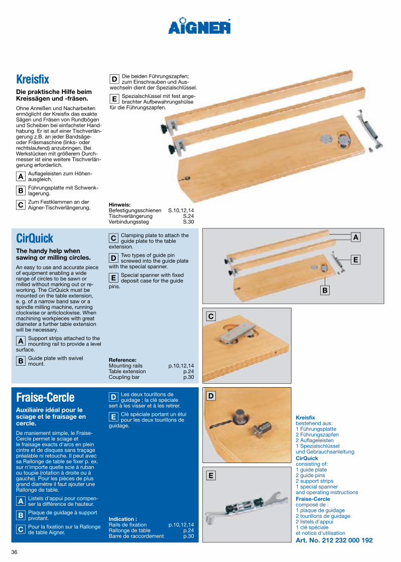
KreisfixDie praktische Hilfe beim Kreissägen und fräsen.Ohne Anreißen und Nacharbeiten ermöglicht der Kreisfix das exakte Sägen und Fräsen von Rundbögen und Scheiben bei einfachster Hand-habung. Er ist auf einer Tischverlän-gerung z.B. an jeder Bandsäge- oder Fräsmaschine (links- oder rechtslaufend) anzubringen. Bei Werkstücken mit größerem Durch-messer ist eine weitere Tischverlän-gerung erforderlich.
Auflageleisten zum Höhen-ausgleich.
Führungsplatte mit Schwenk-lagerung.
Zum Festklemmen an der Aigner-Tischverlängerung.
Die beiden Führungszapfen; zum Einschrauben und Aus-
wechseln dient der Spezialschlüssel.
Spezialschlüssel mit fest ange-brachter Aufbewahrungshülse
für die Führungszapfen.
Fraise-CercleAuxiliaire idéal pour le sciage et le fraisage en cercle.De maniement simple, le Fraise-Cercle permet le sciage et le fraisage exacts d'arcs en plein cintre et de disques sans traçage préalable ni retouche. Il peut avec sa Rallonge de table se fixer p. ex. sur n'importe quelle scie à ruban ou toupie (rotation à droite ou à gauche). Pour les pièces de plus grand diamètre il faut ajouter une Rallonge de table.
Listels d'appui pour compen-ser la différence de hauteur.
Plaque de guidage à support pivotant.
Pour la fixation sur la Rallonge de table Aigner.
Les deux tourillons de guidage ; la clé spéciale
sert à les visser et à les retirer.
Clé spéciale portant un étui pour les deux tourillons de
guidage.
A
B
C
A
B
C
D
E
Kreisfix bestehend aus:1 Führungsplatte2 Führungszapfen2 Auflageleisten1 Spezialschlüsselund GebrauchsanleitungCirQuickconsisting of:1 guide plate2 guide pins2 support strips1 special spannerand operating instructionsFraiseCerclecomposé de :1 plaque de guidage2 tourillons de guidage2 listels d'appui1 clé spécialeet notice d'utilisationArt. No. 212 232 000 192
D
E
CirQuickThe handy help when sawing or milling circles.An easy to use and accurate piece of equipment enabling a wide range of circles to be sawn or milled without marking out or re-working. The CirQuick must be mounted on the table extension, e. g. of a narrow band saw or a spindle milling machine, running clockwise or anticlockwise. When machining workpieces with great diameter a further table extension will be necessary.
Support strips attached to the mounting rail to provide a level
surface.
Guide plate with swivel mount.
Clamping plate to attach the guide plate to the table
extension.
Two types of guide pin screwed into the guide plate
with the special spanner.
Special spanner with fixed deposit case for the guide
pins.
A
B
C
D
E
Indication : Rails de fixation p.10,12,14 Rallonge de table p.24 Barre de raccordement p.30
Reference: Mounting rails p.10,12,14 Table extension p.24 Coupling bar p.30
Hinweis: Befestigungsschienen S.10,12,14 Tischverlängerung S.24 Verbindungssteg S.30

3
5
4
6
1 2
37
Das Werkstück auf dem Führungszapfen der ausge-
schwenkten F ührungs platte.
Aus dem Werkstück werden nun exakte Kreise gesägt
– ohne An reißen.
Kreisfix an einer Tischfräs- maschine.
Exaktes und sicheres Fräsen mit dem Kreisfix und Vor -
schub apparat.
Kreisfräsen von Hand - mit dem Kreisfix und Centrex.
Arbeiten mit dem Kreisfix auf der Kantenschleifmaschine.
Pièce à usiner fixée sur le tou-rillon de la plaque de guidage
en position d'attaque.
Découpage dans la pièce de cercles exacts sans traçage
préalable.
Fraise-Cercle monté sur une toupie.
Fraisage sûr et exact à l'aide du Fraise-Cercle et d'un
entraîneur.
Fraisage circulaire à la main à l'aide du Fraise-Cercle et du
Centrex.
Travail avec le Fraise-Cercle sur la ponceuse de chants.
1
2
3
1
2
3
4
5
6
4
5
6
The workpiece on the guide pin of the swung out guide plate.
Exact circles are now sawn out of the workpiece – no drawing.
CirQuick mounted on the spindle milling machine.
Accurate and safe shaping using a powerfeed with a
single wheel in use.
Hand feeding using the CirQuick and Centrex.
Using the CirQuick on an edge sanding machine.
1
2
3
4
5
6

A
A
150
38
IntegralanschlagEin hervorragendes Arbeitsgerät mit revolutionären Leistungsmerkmalen für sicheres und maßgenaues Arbeiten an der Tischfräsmaschine. Während bei einem herkömmlichen Fräsanschlag die Öffnung im Werk-zeugbereich stets eine Problem- zone darstellt, bietet der Integral- anschlag auch in diesem Bereich eine lückenlose Führungsfläche. Wohldurchdachte Konstruktions-merkmale kennzeichnen seine uni-versellen Einsatzmöglichkeiten bei allen Fräsarbeiten:
● Der Integralanschlag passt zu je- der Tischfräsmaschine; er steht in vier verschiedenen Ausführun- gen zur Verfügung.
● Montage und Einstellungen kön-
nen schnell und einfach ohne zu- sätzliche Werkzeuge vorgenom- men werden.
● Die genaue Anpassung an Werk- zeugdurchmesser und -höhe wird durch stufenlose Verstellbar- keit erreicht.
● Unverlierbare, integrierte Füh - rungs stege garantieren stets eine durchgehende Führungsfläche.
● Weitere Sicherheits- und Arbeits- vorrichtungen können über die seitliche Aufnahme und über die Tragschiene montiert werden.
● Die Oberfläche ist durch Hard- Coat-Schicht vergütet.
Für die schnelle, stabile Befestigung des Integral-
anschlages an der Tisch fräsma -schine sorgt der Klemmexzenter.
Butée IntégraleUn outil exceptionnel aux caractéristiques révolutionnaires, pour un travail à la toupie sûr et précis.Alors que dans une butée conven-tionnelle l'ouverture devant l'outil représente un risque permanent, la Butée Intégrale offre, aussi dans cette zone, un guidage sans soluti-on de continuité. Sa construction, étudiée dans les moindres détails, en fait un outil d'emploi uni-versel dans les travaux de fraisage particulièrement délicats :
● La Butée Intégrale s'adapte sur n'importe quelle toupie ; elle est disponible en quatre versions différentes.
● Montage et mise au point sont simples, rapides et sans l'aide d'outils supplémentaires.
● Le réglage au diamètre et à la hauteur de l'outil s'effectue en continu.
● Les entretoises incorporées, donc imperdables, assurent la continuité de la surface de guidage.
● D'autres dispositifs de travail et de sécurité peuvent se fixer en bout de la Butée et au moyen du Rail de support.
● L'ensemble bénéficie d'un traite- ment de surface „hard-coat“.
Un excentrique de serrage assure la fixation rapide et
solide de la Butée Intégrale sur la toupie.
A
A
Integral fenceAn excellent working unit with revolutionary features to provide accurate and safe machining on a vertical spindle miller.On conventional spindle milling machines bridging the gap between the infeed and outfeed fence can be difficult. The fence uniquely closes this gap allowing the work-piece to be guided past the cutting tool. Well designed and engineered features provide further operational possibilities.
● The integral fence is suitable for most vertical spindle milling machines. Four different versions of the fence are available. ● Mounting and adjusting the fence system is a simple and rapid ope- ration without any additional tool.
● Providing accurate opening and height adjustment for different tool diameter and depth is a simple operation with a wide range of adjustability. ● The guide bars interlock in the outfeed fence case, providing a secure and smooth surface, supporting the workpiece in the non-machined area. ● Other safety and working devices can be mounted in the lateral seats and by means of supporting rail. ● The hard-coat layer on the fence surfaces provides for a reduced friction and wear resistant finish.
The clamping eccentric enables a rapid and stable
fastening of the integral fence to the milling machine.
A
Integralanschlag beide Hälften 500 mm langmit GebrauchsanleitungIntegral fenceeach half 500 mm longwith operating instructionsButée Intégraleles deux moitiés 500 mm de longavec notice d'utilisationArt. No. 213 311 000 193Integralanschlaglinke Hälfte 500 mm langrechte Hälfte 650 mm langmit GebrauchsanleitungIntegral fence left half 500 mm long right half 650 mm long with operating instructionsButée Intégralemoitié gauche 500 mm de longmoitié droite 650 mm de longavec notice d'utilisationArt. No. 213 313 000 193Integralanschlaglinke Hälfte 650 mm langrechte Hälfte 500 mm langmit GebrauchsanleitungIntegral fenceleft half 650 mm longright half 500 mm longwith operating instructionsButée Intégralemoitié gauche 650 mm de longmoitié droite 500 mm de longavec notice d'utilisationArt. No. 213 315 000 193Integralanschlagbeide Hälften 650 mm langmit GebrauchsanleitungIntegral fenceeach half 650 mm longwith operating instructionsButée Intégraleles deux moitiés 650 mm de longavec notice d'utilisationArt. No. 213 317 000 193
Hinweis: Weitere Ausführungen S.40,42,44
Reference: Further versions p.40,42,44
Indication : Autres versions p.40,42,44

1
3
5
2
4
6 7
39
Integralanschlag geöffnet.
Die Führungsstege lassen sich mit einem einfachen Handgriff
herausdrehen.
Mit Ausnahme des Werkzeug-bereiches wird die gesamte
Öffnung im Integralanschlag über-brückt.
Zurückschwenken der nicht benötigten Stege aus dem
Werkzeugbereich.
Der betriebsbereite Integral-anschlag.
Stufenlose Höhenverstellung der Kassette mit den Stegen.
Seitliche Aufnahme für weitere Aigner-Sicherheits- und
Arbeitsvorrichtungen.
Butée Intégrale ouverte.
Les entretoises se dégagent par simple rotation du bouton à
oreilles.
L'ouverture entre les deux moi-tiés de la Butée Intégrale est
entièrement recouverte par les entretoises, excepté dans la zone de travail de l'outil.
Les entretoises non-utilisées, dans la zone de travail de
l'outil, sont rabattues dans leur logement.
La Butée Intégrale Aigner prête à l'emploi.
Réglage en hauteur de la cas-sette et de ses entretoises.
Organe de fixation sur le côté de la Butée pour d'autres dis-
positifs de travail et de sécurité Aigner.
1
2
3
1
2
3
4
5
6
7
4
5
6
7
Integral fence, opened.
Guide bars swung out using the expeller unit in the infeed
fence.
The guide bars span the gap between the infeed and out-
feed fences.
The guide bars not needed are swivelled back into the infeed
fence.
The integral fence is now ready for use.
The height of the cases in the infeed and outfeed fences can
be infinitely varied to give clearance to the cutting tool and guide rails.
Other equipment can be atta-ched by use of the lateral seat
in the ends of the integral fence sections.
1
2
3
4
5
6
7

40
Butée Intégralepour butée Panhans type 204. Fixation par le haut de la Butée Intégrale.
Integralanschlagfür Panhans F räs anschlag Typ 204. Klemmung des Integralanschlags von oben.
Integralanschlag beide Hälften 500 mm langmit GebrauchsanleitungIntegral fenceeach half 500 mm longwith operating instructionsButée Intégraleles deux moitiés 500 mm de longavec notice d'utilisationArt. No. 213 351 000 193Integralanschlaglinke Hälfte 500 mm langrechte Hälfte 650 mm langmit GebrauchsanleitungIntegral fence left half 500 mm long right half 650 mm long with operating instructionsButée Intégralemoitié gauche 500 mm de longmoitié droite 650 mm de longavec notice d'utilisationArt. No. 213 353 000 193Integralanschlaglinke Hälfte 650 mm langrechte Hälfte 500 mm langmit GebrauchsanleitungIntegral fenceleft half 650 mm longright half 500 mm longwith operating instructionsButée Intégralemoitié gauche 650 mm de longmoitié droite 500 mm de longavec notice d'utilisationArt. No. 213 355 000 193Integralanschlagbeide Hälften 650 mm langmit GebrauchsanleitungIntegral fenceeach half 650 mm longwith operating instructionsButée Intégraleles deux moitiés 650 mm de longavec notice d'utilisationArt. No. 213 357 000 193
Hinweis: Weitere Ausführungen S.38,42,44
Indication : Autres versions p.38,42,44
Integral fencefor Panhans fence type 204. The integral fence is clamped from the upper side.
Reference: Further versions p.38,42,44

A
A
A
A
2
3
1
4
B
B
B
B
B
B
B
BA
A
A
A
41
Integralanschlag für Panhans Fräsanschlag mit Klemmbolzen und zwei gleich breiten Klemmleisten
Butée Intégrale pour butée Panhans avec boulons de fixation et deux plaques de fixation d’égale largeur
1 2 3
1 2 3 4
4
Integral fence for Panhans fence with clamping bolts and two clamping strips having identic width
1
A
2
B
3 4
A
B
A
B

42
Butée Intégralepour toupie scm. Fixation de la Butée Intégrale par le haut.
Integralanschlagfür scm F räs maschine. Klemmung des Integral anschlags von oben.
Integralanschlag beide Hälften 500 mm langmit GebrauchsanleitungIntegral fenceeach half 500 mm longwith operating instructionsButée Intégraleles deux moitiés 500 mm de longavec notice d'utilisationArt. No. 213 371 000 193Integralanschlaglinke Hälfte 500 mm langrechte Hälfte 650 mm langmit GebrauchsanleitungIntegral fence left half 500 mm long right half 650 mm long with operating instructionsButée Intégralemoitié gauche 500 mm de longmoitié droite 650 mm de longavec notice d'utilisationArt. No. 213 373 000 193Integralanschlaglinke Hälfte 650 mm langrechte Hälfte 500 mm langmit GebrauchsanleitungIntegral fenceleft half 650 mm longright half 500 mm longwith operating instructionsButée Intégralemoitié gauche 650 mm de longmoitié droite 500 mm de longavec notice d'utilisationArt. No. 213 375 000 193Integralanschlagbeide Hälften 650 mm langmit GebrauchsanleitungIntegral fenceeach half 650 mm longwith operating instructionsButée Intégraleles deux moitiés 650 mm de longavec notice d'utilisationArt. No. 213 377 000 193
Indication : Autres versions p.38,40,44
Integral fencefor scm milling machines. The integral fence is clamped from the upper side.
Reference: Further versions p.38,40,44
Hinweis: Weitere Ausführungen S.38,40,44

A
A
A
A
A
A
A
A
2
3
1
4
43
Butée Intégrale pour toupie scm, avec plaques de fixation
Integralanschlag für scm Fräsmaschine mit Klemmplatten
1 2 3
1 2 3 4
4
Integral fence for scm milling machines with clamping plates
1 2 3 4
A
A
A

B
44
Butée Intégralepour toupie scm avec capteur de contrôle.
CapteurB
Integralanschlagfür scm Fräs maschine mit SensorÜberwachung.
Sensor
Integralanschlagfür scm Fräs maschine mit SensorÜberwachung.
SensorB
Integralanschlag beide Hälften 500 mm langmit GebrauchsanleitungIntegral fenceeach half 500 mm longwith operating instructionsButée Intégraleles deux moitiés 500 mm de longavec notice d'utilisationArt. No. 213 381 000 193Integralanschlaglinke Hälfte 500 mm langrechte Hälfte 650 mm langmit GebrauchsanleitungIntegral fence left half 500 mm long right half 650 mm long with operating instructionsButée Intégralemoitié gauche 500 mm de longmoitié droite 650 mm de longavec notice d'utilisationArt. No. 213 383 000 193Integralanschlaglinke Hälfte 650 mm langrechte Hälfte 500 mm langmit GebrauchsanleitungIntegral fenceleft half 650 mm longright half 500 mm longwith operating instructionsButée Intégralemoitié gauche 650 mm de longmoitié droite 500 mm de longavec notice d'utilisationArt. No. 213 385 000 193Integralanschlagbeide Hälften 650 mm langmit GebrauchsanleitungIntegral fenceeach half 650 mm longwith operating instructionsButée Intégraleles deux moitiés 650 mm de longavec notice d'utilisationArt. No. 213 387 000 193
Integral fencefor sensor controlled scm milling machines.
SensorB
Hinweis: Weitere Ausführungen S.38,40,42
Indication : Autres versions p.38,40,42
Reference: Further versions p.38,40,42

CD
2
3
1
4
C D
CD
C D
CD
C D
CD
C D
45
Integralanschlag für scm Fräsmaschine mit Klemmführungen und Sensorleisten
Butée Intégrale pour toupie scm avec guides de fixation et barrettes de capteur
1 2 3
1 2 3 4
4
Integral fence for scm milling machines with clamping guides and sensor ledges
1 2 3 4
C
D
C
D
D
C

46
FüllstabZum sicheren Führen von dünnen Werkstücken am Integralanschlag.Der Füllstab schließt die untere Aussparung in der linken Kassette des Integralanschlages und schafft dadurch auch in die-sem Be reich eine lückenlose Führungsfläche. Die Oberfläche ist durch Hard-Coat-Schicht vergütet.
Barre de treillisPour le guidage sûr de pièces minces à usiner à la Butée Intégrale.La Barre de treillis obture l'évidement inférieur de la cassette gauche de la Butée Intégrale et offre donc dans cette zone une surface de guidage ininterrompue. La Barre de treillis bénéficie d'un traitement de surface „hard-coat“.
Füllstabmit GebrauchsanleitungFilling barwith operating instructionsBarre de treillisavec notice d'utilisationArt. No. 213 551 000 172
Filling barSafe guidance of thin workpieces at the integral fence.The component prevents thin sec-tions from slipping into the groove at the bottom of the outfeed fence, providing continuity of support. Surface with hard-coat layer.

1
2
3
47
Einlegen des Füllstabes in die untere Aussparung der linken
Kassette.
Festklemmen des Füllstabes.
Werkstück, das unter Einsatz des Füllstabes bearbeitet
wurde.
Mise en place de la Barre de treillis dans l'évidement
inférieur de la cassette gauche.
Blocage de la Barre de treillis.
Pièce travaillée avec une Butée équipée d'une Barre de treillis.
1
2
3
Inserting the filling bar into the lower recess of the outfeed
fence case.
Clamping the filling bar into its working position.
The workpiece after being machined using the filling bar.
1
2
3
1
2
3

A
48
AbstandhalterUnentbehrlich beim Fräsen von leicht kippenden Werkstücken mit dem Integralanschlag.Der Abstandhalter wird in gewünschter Höhe in eine Nut des Integralanschlages geklemmt.
Finger des Abstandhalters ausgestellt.
EcarteurIndispensable pour le travail à la Butée Intégrale de pièces susceptibles de basculer au fraisage.L'Ecarteur se fixe à la hauteur voulue dans une des rainures de la Butée Intégrale.
Doigt de l'Ecarteur sorti.A
A
Abstandhalter mit Sechskant-Winkelschrauben-dreher und GebrauchsanleitungSpreaderwith Allen key and operating instructionsEcarteuravec clé mâle coudée 6 panset notice d'utilisationArt. No. 213 552 000 172
SpreaderIndispensable when machining small unstable workpieces, using the integral fence. The spreader is clamped at the required height, into a groove in the integral fence to prevent the workpiece from tipping.
The support finger of the spreader swung out to
support the machined section.
A

1
2
3
49
Festklemmen des Abstand- halters am Integralanschlag.
Einstellen des Abstandhalters auf die erforderliche Profiltiefe.
Fräsen eines leicht kippenden Werkstückes mit Abstand-
halter.
Serrage de l'Ecarteur sur la Butée Intégrale.
Réglage de l'Ecarteur à la pro-fondeur de profil nécessaire.
Fraisage d'une pièce bascu-lante à l'aide de l'Ecarteur.
1
2
3
1
2
3
Clamping the spreader in the integral fence.
Adjusting the spreader to required profile depth.
Machining an easily tiltable work piece using a spreader as
a support.
1
2
3

A
50
TragschieneWeiteres zweckmäßiges Zubehör zum Integral anschlag.An der Tragschiene wird das Druckmodul z.B. mit Doppelrolle zur Führung der Werkstücke ange-bracht.
Festschrauben der Tragschie-ne am Integralanschlag.
Rail de supportAutre accessoire utile adaptable à la Butée Intégrale.C'est sur le Rail de support que l'on fixe le Module-Presseur, équipé par exemple d'un Galet-Double, pour guider la pièce à usiner.
Vis de fixation du Rail de support sur la Butée Intégrale.A
A
Tragschieneeinschl. 2 Stiftschrauben, Sechs-kant-Winkelschraubendreher und GebrauchsanleitungSupporting railincl. 2 grub screws, Allen key and operating instructionsRail de supporty compris 2 goujons filetés,clé mâle coudée 6 panset notice d'utilisationArt. No. 213 505 000 193
Supporting railAn appropriate unit to be added to the integral fence.The supporting rail is used to hold the pressure module, for example with double wheel, for guidance of the workpiece.
Fixing the supporting rail at the integral fence.A

1
2
3
51
Tragschiene geöffnet.
Tragschiene geschlossen.
Tragschiene mit Druckmodul und Doppelrolle.
Rail de support ouvert.
Rail de support fermé.
Rail de support équipé du Module-Presseur avec Galet-
Double.
1
2
3
1
2
3
Supporting rail, opened.
Supporting rail, closed.
Supporting rail with pressure module and double wheel.
1
2
3

A
52
Fräsbock EZur Auflage beim Fräsen von geschweiften Werkstücken mit hinterschnittenem Profil am Anschlag.
Halteklötze stufenlos ver- stellbar.
Fräsbock Emit Sechskant-Winkelschrauben-dreher und GebrauchsanleitungCutter frame Ewith Allen key and operating instructionsChevalet de fraisage Eavec clé mâle coudée 6 pans et notice d'utilisationArt. No. 214 263 000 192
A
Cutter frame EUsed as an edge support, mounted on the integral fence when machining the face of curved workpieces.
Continuously adjustable retainer blocks.
Chevalet de fraisage ESert d'appui pour le frai sage à la Butée de pièces chantournées à profil contredépouillé.
Cales de fixation coulissantes.
A
A
Indication : Rail de fixation Art. No. 212 108 000 191 p.10 Rail de fixation p.14 Rail de support p.50 Module-Presseur p.96 Galet-Simple p.98 Galet-Double p.98
Reference: Mounting rail Art. No. 212 108 000 191 p.10 Mounting rail p.14 Supporting rail p.50 Pressure module p.96 Single wheel p.98 Double wheel p.98
Hinweis: Befestigungsschiene Art. No. 212 108 000 191 S.10 Befestigungsschiene S.14 Tragschiene S.50 Druckmodul S.96 Einzelrolle S.98 Doppelrolle S.98

1
2
53
Fräsen eines geschweiften Werkstückes mit Fräsbock E,
Einzelrolle und Doppelrolle.
Fräsen eines geschweiften Werkstückes mit Fräsbock E,
Doppelrolle und Vorschubapparat.
1
2
Fraisage d'une pièce chantour-née à l'aide du Chevalet de
fraisage E, du Galet-Simple et du Galet-Double.
Fraisage d'une pièce chantour-née à l'aide du Chevalet de
fraisage E, du Galet-Double et d'un entraîneur.
Machining the face of a curved workpiece supported by cutter
frame E, single and double wheel.
Machining a curved workpiece using a cutter frame E, double
wheel and a power feed.
1
2
1
2

A
E
D
B C
54
Kantix eingestellt zum Abfräsen beidseitig überstehender Kan-
ten an schmalen Werk stücken in ei-nem Arbeitsgang (zwei Fräswerkzeu-ge mit gleichem Durchmesser).
KantixPraktische Hilfe zum Fräsen von Werkstücken mit über stehenden Kanten.Der Kantix lässt sich schnell auf die gewünschte Höhe sicher am Integralanschlag befestigen. Die stufenlose Feineinstellung erfolgt über die Kassetten des Integral-anschlags. Die Oberfläche ist durch Eloxierung vergütet.
Führungssteg wird in die beiden Kantixhälften einge-
schoben.
Klemmkeil.
Fixierbolzen.
Festklemmen des Kantix am Integralanschlag.
A
B
C
D
E
KantixAide pratique pour le fraisage de pièces à chants dépassants.Le Kantix se monte en quelques ins tants à la hauteur désirée sur la Butée Intégrale. Le réglage fin en continu s'effectue par la cassette de la Butée Intégrale. La surface est traitée par anodisation.
La barrette-guide s'enfiche sur chacune des deux parties
du Kantix.
Clavette de serrage.
Goujons de fixation.
Fixation du Kantix sur la Butée Intégrale.
Kantix réglé pour le dressage du chant dépassant sur les
deux faces d'une pièce étroite en un seul passage (deux outils de même diamètre).
A
B
C
E
D
Kantix mit Sechskant-Winkelschrauben-dreher und GebrauchsanleitungKantixwith Allen key and operating in structionsKantixavec clé mâle coudée 6 pans et notice d'utilisationArt. No. 214 264 000 192
Kantix A practical help when milling surfaces protruding from a workpiece.The Kantix may be quickly mount-ed at the desired height to the inte-gral fence. Its continuous fine ad-justment is provided by the cases in the integral fence. The surface is hardened by anodic treatment.
The guide bridge is pushed in-to both halves of the Kantix.
Clamping wedge.
Locating studs.
Fixing the Kantix on the inte-gral fence.
The Kantix is positioned for flush edging both top and bot-
tom protruding surfaces in one pass using two cutter heads of the same diameter.
A
B
C
D
E
Indication : Butée Intégrale p.38,40,42,44
Reference: Integral fence p.38,40,42,44
Hinweis: Integralanschlag S.38,40,42,44

3 4
1
5
2
55
Kantix ohne Führungssteg ein-gestellt zum Abfräsen beidsei-
tig überstehender Kanten an großen Werkstücken in einem Arbeitsgang.
Kantix mit Führungssteg einge-stellt zum einseitigen Abfräsen
der Kanten an schmalen Werk- stücken.
Abfräsen überstehender Kan-ten an schmalen Werkstücken
mit Kantix und Centrex.
Abfräsen überstehender Kan-ten an einem dünnen Werk-
stück mit Kantix und Centrex.
Abfräsen überstehender Kan-ten an einem dicken Werkstück
mit Kantix und Centrex.
1
2
3
4
5
Kantix sans barrette-guide réglé pour le dressage des
chants dépassants sur les deux faces de grandes pièces en un seul passage.
Kantix avec barrette-guide réglé pour le dressage des
chants dépassants sur les deux faces de pièces étroites.
Dressage des chants dépas-sants de pièces étroites avec
Kantix et Centrex.
Dressage des chants dépas-sants d'une pièce mince avec
Kantix et Centrex.
Dressage des chants dépas-sants d'une pièce épaisse
avec Kantix et Centrex.
1
2
3
4
5
Kantix without the guide bridge positioned for flush machining
of the protruding surfaces on a large workpiece in a single pass.
Kantix with the guide bridge in position for flush machining of
projecting surfaces of thin work-pieces.
Flush machining across the end of a narrow workpiece
using the Kantix and the Centrex.
Using the Centrex for guarding and pressure when machining
thin workpieces with the Kantix.
Using the Centrex for guarding and pressure when machining
thick workpieces with the aid of the Kantix.
1
2
3
4
5

A
B
C
56
BündixIdeale Werkstückauflage zum Bündigfräsen von Kanten.Der Bündix lässt sich mühelos ohne Werkzeuge stehend oder liegend an der Befestigungsschiene, am Inte-gralanschlag oder an den Befesti-gungsplatten montieren und sekun-denschnell stufenlos auf die Werk-stückbreite einstellen. Er ge währ-leistet exaktes Bündigfräsen von Kanten aller Art und ermöglicht die Ausnutzung der gesamten Schneiden breite des Werkzeuges.
Die Oberfläche ist durch Eloxierung vergütet.
Länge 1600 mm.
Grundeinstellung auf die Tisch- bzw. Anschlaglänge.
Stufenlose Feineinstellung.
Bündixmit GebrauchsanleitungFlushfixwith operating instructionsAffleurfixeavec notice d'utilisationArt. No. 214 265 000 192
A
B
C
FlushfixIdeal workpiece support for flush machining of lippings.The Flushfix can be mounted easily upright or in the horizontal position. Mounting is carried out without tools to the mounting rail or the in-tegral fence or the mounting plates. The Flushfix is infinitely variable to suit the workpiece width. The de-sign of the Flushfix ensures that the cutter head can be accurately ad-justed to provide a flush finish with the un der side of the workpiece.
Wear resistance is provided by the harden ed anodic finish to
the Flushfix. Length 1600 mm.
Basic adjustment to suit the machine table length.
Accurate and continuous adjustment.
AffleurfixeSupport idéal de la pièce pour le fraisage à fleur d'une baguette de chant.L'Affleurfixe se monte sans effort et sans outils, horizontalement ou ver-ticalement, sur le Rail de fixation, sur la Butée Intégrale ou sur les Plaques de fixation et se règle en quelques secondes à la largeur de la pièce à usiner. Il garantit un frai-sage à fleur exact de n'importe quel chant et permet l'utilisation de toute la largeur de taillant de l'outil.
La surface est traitée par anodisation.
Longueur 1600 mm.
Réglage de base sur la lon-gueur de table ou de butée.
Réglage précis en continu.
A
B
C
A
B
C
Indication : Rails de fixation p.10,12,16 Butée Intégrale p.38,40,42,44 Module-Presseur p.96 Galet-Simple p.98
Reference: Mounting rails p.10,12,16 Integral fence p.38,40,42,44 Pressure module p.96 Single wheel p.98
Hinweis: Befestigungsschienen S.10,12,16Integralanschlag S.38,40,42,44 Druckmodul S.96 Einzelrolle S.98

1
2
3
57
Bündigfräsen der Kanten eines schmalen, liegenden Werk-
stückes mit Bündix und Centrex.
Bündigfräsen der Kanten eines breiten, liegenden Werkstückes
mit Bündix und Centrex.
Bündigfräsen der Kanten eines breiten, stehenden Werk-
stückes mit Bündix und Druckmodul mit Einzelrolle.
1
2
3
Fraisage à fleur des chants d'une pièce étroite à plat avec
Affleurfixe et Centrex.
Fraisage à fleur des chants d'une pièce large à plat avec
Affleurfixe et Centrex.
Fraisage à fleur des chants d'une pièce large debout avec
Affleurfixe et Modules-Presseurs munis d'un Galet-Simple.
Flush machining of the pro-jecting edges of a narrow, flat
workpiece using a Flushfix and Centrex.
Flush machining of the pro-jecting edges of a wide, flat
workpiece using a Flushfix and Centrex.
Flush machining the projecting lippings on a wide workpiece in
the upright position. The workpieces are supported by Flushfix, pressure modules and single wheels.
1
2
3
1
2
3

A
D
B
C
3,5
58
AbplattprofiAbsolut notwendig, insbesondere zum Abplatten kleiner Werkstücke.Der Abplattprofi gewährleistet ein exaktes und sicheres Abplatten der Werkstücke bei ein- und zweiseiti-ger Bearbeitung sowie mit oben oder unten laufendem Fräswerk-zeug. Er lässt sich schnell und si-cher am Integralanschlag befesti-gen. Die stufenlose Feineinstellung erfolgt ohne Werkzeug über die Kassetten des Integralanschlages.
Führungswinkel eingestellt für Fräsarbeiten mit unten laufen-
dem Fräswerkzeug.
Führungswinkel eingestellt für Fräsarbeiten mit oben laufen-
dem Fräswerkzeug.
Klemmkeil.
Festklemmen des Abplattprofi am Integralanschlag.
A
B
C
D
Pro-Plate-BandeAbsolument nécessaire pour élégir les petites pièces.Le Pro-Plate-Bande garantit l'élé-gissement sûr et exact des pièces en un ou deux passages avec outil travaillant par-dessus ou par-des-sous. Il se fixe facilement et de façon sûre à la Butée Intégrale. Le réglage fin s'effectue en continu et sans outil par l'intermédiaire de la cassette de la Butée Intégrale.
Équerre de guidage réglée pour un fraisage par le des-
sous.
Équerre de guidage réglée pour fraisage par le dessus.
Clavette de serrage.
Fixation du Pro-Plate-Bande sur la Butée Intégrale.
A
B
C
D
Abplattprofimit Sechskant-Winkelschrauben-dreher und GebrauchsanleitungFlatserverwith Allen key and operating in structionsProPlateBandeavec clé mâle coudée 6 pans et notice d'utilisationArt. No. 214 267 000 192
Flatserver An essential device for use when fielding and raising small panels. The Flatserver ensures a precise and safe presentation of work-pieces to the cutter head when fielding and raising panels on one or both surfaces. The cutter head can be used above or below the workpieces. It may be mounted quickly and safely to the integral fence. Its continuous fine adjust-ment is provided by the cases in the integral fence without any additional tool.
Guide angle in position for machining with the cutter
head below the workpiece.
Guide angle in position for machining with the cutter
head above the workpiece.
Clamping wedge.
Fixing the Flatserver to the integral fence.
A
B
C
D
Indication : Butée Intégrale p.38,40,42,44 Rail de support p.50 Module-Presseur p.96 Patin Demi-Rond p.104 Guide de glissement p.104 Patin Demi-Rond V p.104
Reference: Integral fence p.38,40,42,44 Supporting rail p.50 Pressure module p.96 Pressure shield p.104 Sliding guide p.104 Pressure shield V p.104
Hinweis: Integralanschlag S.38,40,42,44 Tragschiene S.50 Druckmodul S.96 Halbrundschuh S.104 Führungsgleiter S.104 Halbrundschuh V S.104

1
2 3
4 5
3,5
59
Abplatten der ersten Seite eines Werkstückes mit unten
laufendem Fräswerkzeug, Abplatt-profi und Halbrundschuh.
Abplatten der zweiten Seite eines Werkstückes mit unten
laufendem Fräswerkzeug, Abplatt-profi und Halbrundschuh.
Abplatten der ersten Seite eines Werkstückes mit oben
laufendem Fräswerkzeug, Abplatt-profi und Halbrundschuh.
Abplatten der zweiten Seite eines Werkstückes mit oben
laufendem Fräswerkzeug, Abplatt-profi und Halbrundschuh.
Abplatten eines Werkstückes mit oben laufendem Fräswerk-
zeug, Abplattprofi, Führungsgleiter mit Führungsaufnahme und Halbrundschuh V.
1
2
3
4
5
Élégissement du premier côté d'une pièce avec un outil tra-
vaillant par-dessous, le Pro-Plate-Bande et le Presseur Demi-Rond.
Élégissement du deuxième côté d'une pièce avec un outil
travaillant par-dessous, le Pro-Plate-Bande et le Presseur Demi-Rond.
Élégissement du premier côté d'une pièce avec un outil tra-
vaillant par-dessus, le Pro-Plate-Bande et le Presseur Demi-Rond.
Élégissement du deuxième côté d'une pièce avec un outil
travaillant par-dessus, le Pro-Plate-Bande et le Patin Demi-Rond.
Élégissement d’une pièce avec outil travaillant par-dessus,
Pro-Plate-Bande, Guide de glisse-ment avec logement de guidage et Patin Demi-Rond V.
1
2
3
4
5
Machining the workpiece on the first surface with the cutter
head below the workpiece using the Flatserver and pressure shield.
Machining the workpiece on the second surface with the
cutter head below the workpiece using the Flatserver and pressure shield.
Machining the workpiece on the first surface with the cutter
head above, Flatserver and pressure shield.
Machining the workpiece on the second surface with the
cutter head above, Flatserver and pressure shield.
Machining a workpiece with the cutter head above, Flat-
server, sliding guide with guide support and pressure shield V.
1
2
3
4
5

AB
E
FC
D
G
H
I
60
ContermaxZum exakten und schnellen Profilieren von Werkstücken an der Querseite.Der Contermax ermöglicht ein si cheres und wirtschaftliches Arbei-ten. Durch die präzise Werkstück-führung wird eine hohe Maßgenau-igkeit erreicht. Blitzschneller Wech-sel des Werkstückes mit neuartiger Klemmung.
Grundkörper aus Aluminium, Oberfläche durch Eloxierung
vergütet, Länge 420 mm, Spann- länge 200 mm.
Der lange, stabile Handgriff aus Aluminium, kunststoffbe-
schichtet, gewährleistet eine siche-re Führung des Werkstückes.
Die stufenlos verstellbare Schiebeleiste wird mit Senk-
schrauben auf ein Splitterholz ge-schraubt.
Flügelschraube zum Verstellen des Splitterholzes.
Klemmbacke.
Drehknopf zum Auslösen der Klemmung.
Splitterholz ermöglicht ein
ausrissfreies Fräsen.
Lange Führung aus Holz.
Freiraum für über- stehendes Werk-
zeug.
Contermaxmit GebrauchsanleitungContermax with operating instructionsContermaxavec notice d'utilisationArt. No. 214 287 000 193
A
BI
C
D
E
F
G
H
ContermaxA precise and rapid means for providing a profile across the end of a timber section.The Contermax enables safe and efficient working across the end of a timber section whilst minimising end grain breakout. Accurate posi-tioning and guidance across the face of the cutting tool ensures close tolerances to be easily achieved.
The body of the tool is made from aluminium and hardened
by anodic treatment. The overall length is 420 mm, the clamping length is 200 mm.
The long plastic coated hand-le provides for excellent grip
and enables safe and accurate guidance across the face of the cutting tool.
The infinitely adjustable sliding strip is fixed to break out
prevention block by countersunk screws.
Wingscrew for positioning the break out block.
Clamping jaw.
Clamping knob.
Break out prevention block.
Flywood guide strip.
Clearance for the projection of the cutting tool.
Contermax Pour le profilage exact et rapide en bout de pièce.Le Contermax permet un travail sûr et économique. Grâce au guidage exact de la pièce, on obtient une grande précision dimensionnelle. Changement ultra-rapide de la pièce à usiner grâce à un nouveau système de serrage.
Corps de base en aluminium traité par anodisation, lon-
gueur 420 mm, ouverture de ser-rage 200 mm.
La poignée en aluminium, lon-gue et robuste, assure un gui-
dage sûr de la pièce.
La barrette coulissante se fixe par des vis à tête fraisée sur
un pare-éclats.
Vis à oreilles pour le déplace-ment du pare-éclats.
Mâchoire de serrage.
Bouton à tourner pour déclencher le serrage.
Le pare-éclats assure un frai-sage sans éclats.
Bois de guidage sur une grande longueur.
Espace libre pour dépasse-ment de l'outil.
A
B
C
D
E
F
H
I
G
A
B
C
D
E
F
G
H
I
Design Patente im In und Ausland German and foreign design patents Design breveté en Allemagne et à l'étranger

1
2
3
61
Profilieren eines schmalen Werkstückes an der Querseite.
Profilieren eines besonders breiten Werkstückes an der
Querseite.
Profilieren eines langen Werk-stückes an der Querseite mit
Tischverlängerung.
1
2
3
Profilage en bout d'une pièce étroite.
Profilage en bout d'une pièce très large.
Profilage en bout d'une pièce longue à l'aide de la Rallonge
de table.
Counter profiling the end of a narrow workpiece.
Counter profiling the end of a wide workpiece.
Counter profiling the end of a long workpiece supported on
a table extension.
1
2
3
1
2
3

BA
DC
62
GlasleisterZum sicheren Heraustrennen der Glasleisten aus den Rahmenhölzern.Der Glasleister wird einfach zwischen die Anschlaghälften ge-klemmt. Die mitgelieferten Distanz- gabeln gleichen unterschiedliche Rahmenholzdicken aus.
Verwendung ohne Distanzgabel.
Verwendung mit Distanzgabel von 4 mm.
Verwendung mit Distanzgabel von 8 mm.
Verwendung mit Distanzgabel von 12 mm.
Glasleistermit GebrauchsanleitungGlassledgerwith operating instructionsListonvitreavec notice d'utilisationArt. No. 214 292 000 192
A
B
C
D
GlassledgerThis device enables glazing beads to be sawn from previously milled sections of window framings.The glassledger is simply clamped between the two halves of the integral fence. Spacer forks are provided to adjust for different widths of window framings.
Use without spacer fork.
Use with the 4 mm spacer fork.
Use with the 8 mm spacer fork.
Use with the 12 mm spacer fork.
ListonvitrePour la découpe exacte des parcloses dans les bois de cadre.Le Listonvitre se serre simplement entre les deux moitiés de la Butée. Les fourchettes d'écartement livrées avec lui compensent les différences d'épaisseur des cadres de bois.
Utilisation sans fourchette d'écartement.
Utilisation avec fourchette d'écartement de 4 mm.
Utilisation avec fourchette d'écartement de 8 mm.
Utilisation avec fourchette d'écartement de 12 mm.
A
B
C
D
A
B
C
D
Indication : Autres versions p.64
Reference: Further versions p.64
Hinweis: Weitere Ausführungen S.64

1
2
63
Glasleister am Fräsanschlag befestigt.
Glasleister beim Heraustrennen der Glasleiste unter Verwen-
dung des Centrex.
1
2
Listonvitre fixé au guide de toupie.
Listonvitre au cours de la découpe de la parclose à l'aide
du Centrex.
Glassledger attached to the integral fence.
Glassledger removing the glazing bead using a circular
saw blade and Centrex.
1
2
1
2

I
II
A68 78 88
22,512,5 32,5
20
B90
20
21,5
64
GlasleisterZum sicheren Heraus trennen der Glasleisten aus den Rahmenhölzern.Der Glasleister wird einfach zwischen die Anschlaghälften geklemmt.
Passend für Rahmenhölzer in Abbildung
GlasleisterPassend für Rahmenhölzer in Abbildung
GlasleisterAbbildung I mit GebrauchsanleitungGlassledgerfigure I with operating instructionsListonvitreFigure I avec notice d'utilisationArt. No. 214 293 000 192GlasleisterAbbildung II mit GebrauchsanleitungGlassledgerfigure II with operating instructionsListonvitreFigure II avec notice d'utilisationArt. No. 214 295 000 192
A
B
Glas sledgerThis device enables glazing beads to be sawn from previously milled sections of window framing.The Glassledger is simply clamped between the two halves of the integral fence.
Suitable for window framings as illustrated in figure
GlassledgerSuitable for window framings as illustrated in figure
ListonvitrePour la découpe exacte des parcloses dans les bois de cadre.Le Listonvitre se serre simplement entre les deux moitiés de la Butée.
Convient pour les bois d’encadrement en figure
ListonvitreAdapté pour les bois de cadre de la figure
A
B
A
B
I II
I II
I II
Indication : Autres version p.62
Reference: Further version p.62
Hinweis: Weitere Ausführung S.62

1
2
65
Listonvitre au cours de la découpe de la parclose à
l’aide du Centrex.
Glasleister beim Heraus-trennen der Glasleiste
unter Verwendung des Centrex.
1 2
Glassledger removing the glazing bead using a
circular saw blade and Centrex.
1 2
1 2

A
A
B
C
I
II
66
KlemmschuhZur Aufnahme diverser Vorrichtungen.Die Klemmschuhe können an der Befestigungsschiene, am Integral-anschlag und an der Befestigungs-platte zur Aufnahme von Vorrich-tungen angebracht werden.
Länge 40 mm.
Länge 172 mm.
Aus Aluminium, Oberfläche durch Eloxierung vergütet.
Zwei Gewinde M 6.
Zwei Gewinde M 8.
KlemmschuhLänge 40 mmmit GebrauchsanleitungClamping shoelength 40 mmwith operating instructionsPince de serragelongueur 40 mmavec notice d'utilisationArt. No. 212 262 000 192KlemmschuhLänge 172 mmmit GebrauchsanleitungClamping shoelength 172 mmwith operating instructionsPince de serragelongueur 172 mmavec notice d'utilisationArt. No. 212 266 000 192
A
B
C
Clamping shoeFor fixing various working units.The clamping shoes may be attach ed to the mounting rail, to the integral fence or to the mount-ing plate in order to fix working units.
Length 40 mm.
Length 172 mm.
Aluminium, surface hardened by anodic treatment.
Two threaded holes M 6.
Two threaded holes M 8.
Pince de serragePour la fixation de divers dispositifs.Les Pinces de serrage peuvent s'adapter sur le Rail de fixation, sur la Butée Intégrale et sur la Plaque de fixation pour recevoir divers dispositifs.
Longueur 40 mm.
Longueur 172 mm.
En aluminium, surface traitée par anodisation.
Deux filetages M 6.
Deux filetages M 8.
A
B
C
A
B
C
I
II
I
II
I
II
Indication : Rails de fixation p.10,12.16 Plaques de fixation p.68
Reference: Mounting rails p.10,12,16 Mountingplate p.68
Hinweis: Befestigungsschienen S.10,12,16 Befestigungsplatten S.68

1
3
5
2
4
6
67
Klemmschuhe an der Be-festigungsschiene ange-
bracht.
Klemmschuhe mit selbst-gefertigter Vorrichtung an
der Befestigungsschiene.
Klemmschuh am Integral- anschlag.
Klemmschuh an der Befesti-gungsplatte.
3 4
5
6
Pinces de serrage sur le Rail de fixation.
Pinces de serrage sur le Rail de fixation avec un
dispositif fait soi-même.
Pince de serrage sur la Butée Intégrale.
Pince de serrage sur la Plaque de fixation.
Clamping shoes attached to the mounting rail.
Clamping shoes fitted with devices made by the
user, attached to the mounting rail.
Clamping shoe attached to the integral fence.
Clamping shoe attached to the mounting plate.
1 2
3 4
5
6
1 2
3 4
5
6
1 2

90
I
I
II
68
Klemmer (1 Stück) mit GebrauchsanleitungClamp(1 piece) with operating instructionsAttache(1 pièce) avec notice d'utilisation Art. No. 212 273 000 192Befestigungsplatten1 Satz (2 Stück) mit GebrauchsanleitungMounting plates1 set (2 pieces) with operating instructionsPlaques de fixation1 jeu (2 pièces) avec notice d'utilisationArt. No. 213 503 000 172
KlemmerUniverselle Halterung für verschiedene Sicherheits vorrichtungen.Der Klemmer spannt Sicherheits-vorrichtungen sicher und schnell in waagerechter und senkrechter Stel-lung. Be fes tigt wird der Klemmer in der Befestigungsschiene, an den Befestigungsplatten oder am Integralanschlag.
Befestigungs - platten
ClampUniversal support for a wide range of safety equipment.The clamp positions safety equip-ment firmly and quickly in both horizontal and vertical positions. The clamp is fastended to the mounting rail, to the mounting plates or to the integral fence.
Mounting plates
AttacheAttache universelle utilisable pour différents dispositifs de sécurité. L'Attache fixe de façon sûre et rapide des dispositifs de sécurité en position horizontale ou verticale. L'Attache s'adapte sur le Rail de fixation, sur les Plaques de fixation ou sur la Butée Intégrale.
Plaques de fixation
I
II
I
II
I
II
Indication : Rails de fixation p.10,12,16 Adaptateur de fixation p.18,20
Reference: Mounting rails p.10,12,16 Mounting adapter p.18,20
Hinweis: Befestigungsschienen S.10,12,16 Befestigungsadapter S.18,20

1
3
5
2
4
6
69
Klemmer am Integralanschlag.
Klemmer an der Befestigungs-platte.
Klemmer waagrecht direkt am Fräsanschlag (min. Stellung).
Maximaler Klemmbereich in waagrechter Lage.
Klemmer in Endstellung unten für senkrechtes Spannen.
Klemmer in Endstellung oben für senkrechtes Spannen.
1
2
3
4
5
6
Attache sur la Butée Intégrale.
Attache sur la Plaque de fixation.
Attache, fixation horizontale sur le guide de fraisage
(éloignement minimum).
Éloignement maximum en position horizontale.
Attache, fixation verticale, en position basse.
Attache, fixation verticale, en position haute.
1
2
3
4
5
6
Clamp attached to the integral fence.
Clamp attached to the mounting plate.
Clamp set horizontally straight up to the spindle fence
(min. position).
Maximum clamping range in horizontal position.
Clamp in lowest position for vertical gripping.
Clamp in highest position for vertical gripping.
1
2
3
4
5
6

A
D
F
BCC
E
G
75
75
70
DistanzhalterDarf an keinem Vorschubapparat fehlen. Der Distanzhalter schützt vor Beschädigungen an Vorschubrollen, Fräswerkzeug und Anschlaglineal.Schnelles und stufenloses Einstel-len des Abstandes zwischen Vor-schubapparat und Anschlaglineal mittels K lemm hebel.
Maximale Verstellung nach beiden Seiten.
Klemmhebel.
Stützkappen aus Kunststoff vermeiden Beschädigungen
am Anschlaglineal.
Vier Zylinderschrauben zum Befestigen am Vorschub-
apparat. Austauschbar mit Gewin-destiften E.
Acht Gewindestifte zum Aus-gleich unebener Befestigungs-
flächen. Austauschbar mit Zylinder-schrauben D.
Distanzhalter an unebe-nen Flächen des Vor-
schubapparates montiert. Aus-gleich der Unebenheit durch Gewindestifte.
A
B
C
D
E
F G
DistanceurNe doit manquer sur aucun entraîneur. Le Distanceur protège les rouleaux d'entraînement, les outils de fraisage et les joues de la butée.Réglage rapide et en continu de la distance entre l'entraîneur et la butée au moyen de leviers de serrage.
Réglage maximum des deux côtés.
Levier de serrage.
Butoirs de protection pour éviter d'abîmer les joues de
la butée.
Quatre vis à tête cylindrique pour la fixation sur l'entraî-
neur. Rem plaçables par des vis sans tête E.
Huit vis sans tête pour com-penser les inégalités des sur-
faces non parfaitement planes. Rem plaçables par des vis à tête cylindrique D.
Distanceur monté sur une surface non plane
de l'entraîneur. Compensation de non-plan éité par des vis sans tête.
A
B
C
E
F G
D
Distanzhaltermit Bohrschablone und GebrauchsanleitungSpacerwith bore template and operating i n structionsDistanceur avec gabarit de perçage et notice d'utilisationArt. No. 212 282 000 192
Spacer An essential device for all powerfeed units. The spacer once set prevents the feed wheels from contacting the rotating cutter head, it also reduces the risk of feed wheel damage to the fence faces.Quick and infinite adjustment of the distance between feed unit and machining fence by means of the clamp ing l ever.
Maximum shifting to both sides.
Clamping lever.
Plastic end cap protects the machine fence against
dam age.
Four socket head cap screws for fastening the spacer to the
feed unit. They are interchangeable with the hex-socket set screws E.
Eight hex-socket set screws to compensate uneven
mount ing surfaces. Interchange -ab le with socket head cap screws D.
Spacer fastened to un-even surfaces of the feed
unit. The hex-socket set screws compensate for unevenness.
A
B
C
D
E
F G
Indication : Accessoires de fixation p.72
Reference: Mounting accessory p.72
Hinweis: Befestigungszubehör S.72

1
2
71
Distanzhalter beidseitig am Vorschubapparat montiert.
Distanzhalter sichert den ein-gestellten Abstand. Vorschub-
apparat schräg gestellt.
1
2
Distanceur monté de chaque côté de l'entraîneur.
Distanceur assurant la distance réglée. Entraîneur placé en
biais.
1
2
Spacer mounted on both ends of the feed unit.
Spacer guarantees the dis-tance set. Feed unit is in in-
clined position.
1
2

I
II
III
V
IV
I
II
III
IV
70
70
70
70
8065
35
35
2540
35
ø 6,2
ø 6,2
35
130°
140°
ø 6,2
ø 6,2
72
Montageplatte Zum Anbau des Distanzhalters an einen Vorschubapparat.Die Montageplatte ist erforderlich, wenn der Distanzhalter am Vor-schubapparat nicht auf die richtige Höhe angebaut werden kann.
Montagewinkelerforderlich, wenn die Form des Gehäuses keine andere Befesti-gung des Distanzhalters erlaubt.
Distanzhülsenerforderlich, wenn z.B. am Vor-schubapparat außen Bürsten angebracht sind.
Montageplatte Mounting plate Plaque de montage 70 x 65 Art. No. 212 291 000 172Montageplatte Mounting plate Plaque de montage 70 x 80 Art. No. 212 293 000 172Montagewinkel Mounting angle Équerre de montage 70 x 25 Art. No. 212 295 000 172Montagewinkel Mounting angle Équerre de montage 70 x 40 Art. No. 212 297 000 172Distanzhülsen (2 Stück) mit Zylinderschrauben und Sechskantmuttern Spacer sleeves (2 pieces) with socket head cap screws and hexagon nuts Douilles d’écartement (2 pièces) avec vis à tête cylindrique et écrou hexagonal Art. No. 212 298 000 172
I II
III IV
V
Plaque de montagePour adapter le Distanceur sur un entraîneur.La Plaque de montage est néces-saire lorsque le Distanceur ne peut pas être monté à la bonne hauteur sur l’entraîneur.
Équerre de montageNécessaire lorsque la forme du boîtier ne permet pas d’autre fixation du Distanceur.
Douilles d’écartementNécessaires lorsque p. ex. des brosses extérieures sont montées sur l’entraîneur.
I II
III IV
V
Mounting plateFor fixing the spacer on a feed unit.The mounting plate is required when it is not possible to fasten the spacer on the feed unit in the exact height.
Mounting angleNecessary when the shape of the feed unit housing does not allow to fasten the spacer in another way.
Spacer sleeves Required e. g. when the feed unit is provided with outer brushes.
I II
III IV
V

1 2
3 4
73
Distanzhalter mit Montage-
platte, Montagewinkel und Distanz-hülsen am Vorschubapparat mon-tiert.
Distanceur avec Plaque de
montage, Equerre de montage et Douilles d’écartement montées sur l’entraîneur.
1 2 3 4
1 2 3 4
Spacer fasten-ed on the feed
unit by means of a mounting plate, mounting angle and spacer sleeves.
1 2 3 4

E
A B C
F
G
H
D
74
DickenanschlagDer ideale Anschlag zum Fräsen von Werkstücken auf exakte Dicke.Der Dickenanschlag ermöglicht bei Rechts- und Linkslauf ein einwand-freies Fräsen auch bei kurzen Werk-stücken ohne Einschläge über die ganze Länge.
Er ist unerlässlich bei allen Fräsar-beiten, bei denen die Anschlaghälf-ten nicht überbrückt werden kön-nen, insbesondere bei dünnen und kleinen Werkstücken. Die Maßein-stellung erfolgt mittels eines Mikro-prozessors und digitaler Anzeige.
Anschlaglineal liegend für niedrige Werkstücke.
Länge 1200 mm.
Zusatzlineal für dünne und schmale Werkstücke.
Maßskala für Zusatzlineal.
Führungsstange der Parallel-verstellung.
Befestigung des hochgestell-ten Anschlaglineals für hohe
Werkstücke.
Rändelschraube zum Befesti-gen des Dickenanschlags.
Digitalanzeige am Maßstab.
Einfacher Batterie -
wechsel.
Dickenanschlagmit Sechskant-Winkelschrauben-dreher und GebrauchsanleitungThickness stopwith Allen key and operating instructionsButée d'épaisseuravec clé mâle coudée 6 panset notice d'utilisationArt. No. 213 716 000 193
A
B
C
D
E
F
G
H
Thickness stopIdeal as a back fence when machining workpieces to an exact width or thickness. It can be used when an edge mould is being machined as part of the progress.The thickness stop ensures high quality finish even on short pieces. The thickness stop is very effective for machining operations where the workpiece is shorter than the fences on the machine due to its unique design. Thin workpieces are supported by the back fence avoid-ing the possibility of vibration.
The back fence in the horizon-tal position for flat workpieces.
Length 1200 mm.
Additional gib for thin and narrow workpieces.
Measurement scale for the additional gib.
Link bar for the parallel displacement system.
Back fence mounted in the vertical posi tion for work-
pieces being fed upright.
Knurled bolt for attaching the thickness stop to the
mounting rail.
Digital measurement display.
Simple battery change.
Butée d'épaisseurLa Butée idéale pour le fraisage à une épaisseur exacte.La Butée d'épaisseur permet un fraisage parfait, en rotation à droite ou à gauche, même pour les pièces courtes, sans ressauts, sur toute la longueur.
Elle est indispensable pour tous les travaux de fraisage pour lesquels on ne peut assurer la continuité des deux moitiés de guide, en parti-culier pour les pièces de petite dimension et de faible épaisseur.
Le réglage de la cote se fait par micro-processeur et affichage numérique.
Réglette de butée à plat pour pièces basses.
Longueur 1200 mm.
Réglette accessoire pour pièces minces et étroites.
Graduation pour la réglette accessoire.
Tige-guide pour le déplace-ment parallèle.
Fixation de la réglette de butée en position relevée pour
les pièces hautes.
Vis moletée pour fixer la Butée d'épaisseur.
Affichage numérique sur la règle de mesure.
Remplacement facile de la pile.
A
B
C
D
E
F
G
H
A
B
C
D
E
F
G
HIndication : Rail de fixation Art. No. 212 108 000 191 p.10 Rail de fixation p.14 Rail de support p.50 Module-Presseur p.96 Patin-Guide p.100 Joues de pression p.108
Reference: Mounting Rail Art. No. 212 108 000 191 p.10 Mounting Rail p.14 Supporting rail p.50 Pressure module p.96 Slide shoe p.100 Pressure jaws p.108
Hinweis: Befestigungsschiene Art. No. 212 108 000 191 S.10 Befestigungsschiene S.14 Tragschiene S.50 Druckmodul S.96 Gleitschuh S.100 Druckbacken S.108

1
2
3
75
Fräsen eines Werkstückes am liegenden Anschlaglineal mit
Druck backen und Gleitschuh.
Fräsen eines dünnen und schmalen Werkstückes am
Zusatzlineal mit Druckbacken und Gleit schuh.
Fräsen eines Werkstückes am hoch gestellten Ansc hlaglineal
mit Druckbacken und Gleitschuh.
1
3
2
Fraisage d'une pièce sur réglette de butée couchée,
avec Joues de pression et Patin-Guide.
Fraisage d'une pièce mince et étroite sur la réglette acces-
soire avec Joues de pression et Patin-Guide.
Fraisage d'une pièce sur la réglette de butée relevée avec
Joues de pression et Patin-Guide.
Machining a workpiece with the hori zon tal back fence,
pressure jaws and slide shoe.
Machining thin and narrow workpieces with the additional
gib in position using the pressure jaws and slide shoe.
Machining a workpiece with the back fence in vertical
position using the pressure jaws and slide shoe.
1
3
2
1
2
3

H
I
C
DAGB
F E
76
BogenfräsmasterMit integrierter Staub und Späneerfassung. Zum wirtschaftlichen, maßgenauen und sicheren Fräsen von bogen und ringförmigen Werkstücken.Diese Sicherheits- und Arbeitsvor-rich tung ermöglicht das schnelle und gefahrlose Fräsen von bogen-för mi gen Werkstücken, auch mit dem Vorschubapparat. Der Bogen-fräsmaster lässt sich auf jeder Tisch- fräsmaschine ohne Werkzeuge ein-fach und schnell befestigen und einstellen. Mit ihm kann im Links- und Rechtslauf gefräst werden.
Stabiles Gehäuse aus Alumini-um mit Hard-Coat-Schicht.
Der transparente Schutz-schirm ermöglicht die Sicht
auf das Werkzeug. Mit der Fede-
rung des Schutzschirms kann der erforderliche Druck auf das Werk-stück eingestellt werden.
Die integrierte für Rechts- und Linkslauf stufenlos verstellba-
re Anlaufleiste in Ruhestellung.
Integrierter Bremskeil in der Anlaufleiste.
Die Befestigungsschrauben werden in Ruhestellung durch
ein integriertes Federsystem zur Schonung der Tischoberfläche an-gehoben und fixiert.
Die Abdeckbürsten lassen sich beliebig einstellen.
Anschluß für Absaugung ø 120 mm.
Durch Schwenken um 90 Grad wird die Anlaufleiste in
Arbeits- bzw. Ruhestellung ge-bracht, rastet automatisch ein.
Der Bremskeil sorgt für den Stillstand des Anlaufrings.
Bogenfräsmasterpassend für Werkzeug ø bis 150 mm mit Bohrschablone und GebrauchsanleitungBowmouldMastersuitable for tool diameters up to 150 mm with bore template andoperating instructionsChantournixpour ø d'outil jusqu'à 150 mmavec gabarit de perçageet notice d'utilisationArt. No. 214 366 000 192Bogenfräsmasterpassend für Werkzeug ø bis 220 mmmit Bohrschablone undGebrauchsanleitungBowmouldMastersuitable for tool diameters up to 220 mm with bore template and operating instructionsChantournixpour ø d'outil jusqu'à 220 mmavec gabarit de perçageet notice d'utilisationArt. No. 214 383 000 192
A
B
C
E
F
D
H
G
I
BowmouldMasterWith integral dust and chip collection. To machine curved and circular workpieces economically, accurately and with maximum regard for safety.This safety and working unit enab les fast and low risk milling of curved workpieces. The power feed unit can also be used with this device. The BowmouldMaster can be easily and quickly fitted to the table of spindle miller without the use of tools. A template is provided for the initial drilling and tapp ing the machine table. Adjustment for guide plate height and position is both quick and accurate. It is possible to use the BowmouldMaster for both clockwise and counter-clockwise machining.
Solid case made of aluminium with hard-coat layer.
The tool is visible through the transparent shield. The spring
loading of the shield is used to adjust the necessary pressure on the work-piece.
The integrated leading on strip in the idle position; infinitely ad-
justable for clockwise or counter- clockwise machining.
The brake shoe, integrated into the leading on strip.In idle position, the mounting screws are lifted and fixed by
an integrated system of springs in order to save the table surface.
The guard brushes are infinitely adjustable.Exhaust tube connection ø 120 mm.The leading on strip may be swung through 90° from its
wor king position into its inoperative position and vice versa. In both posi-tions it is automatically locked.
The brake shoe prevents the guide bearing from rotating to
provide smoother initial contact with the guide.
ChantournixAvec système de récupération des poussières et des copeaux. Pour le fraisage économique, exact et sûr de pièces courbes et annulaires.Ce dispositif de travail et de sécu-rité permet le fraisage rapide et sans danger de pièces courbes, avec ou sans entraîneur. Le Chantournix peut se monter et se régler sans outil de façon simple et rapide sur n'importe quelle table de toupie. Il permet le fraisage dans les deux sens de rotation.
Capot robuste en alumi nium traité „hard-coat“.
Le bouclier de protection transparent ne cache pas la
vue sur l'outil. Grâce au système
de ressorts du bouclier, on peut ajuster la pression nécessaire pour maintenir la pièce.
Butée d'attaque intégrée, pour rotation à droite ou à gauche,
réglable en continu, en position de repos.
Sabot de freinage intégré dans la butée d'attaque.
Les vis de fixation, en cas de non-utilisation, sont mainte-
nues relevées par un ressort pour éviter d'abîmer la table.
Les brosses latérales sont réglables à volonté.
Raccord d’aspiration ø 120 mm.
Par pivotement de 90 degrés, la butée d'attaque s'enclen-
che automatiquement en position de travail ou de repos.
Le sabot de freinage sert à l'immobilisation du guide
à billes.
A
B
C
E
G
F
D
H
I
A
B
E
C
F
D
H
I
G

1
4
2
3
77
Bogenfräsmaster mit Anlaufring.
Fräsen eines ringförmigen Werkstückes an der Innen seite
mit dem Bogen fräs master. Kleinster Radius 145 mm bei Bogenfräsma-ster 214 366 000 192. Kleinster Ra-dius 195 mm bei Bogen fräs master 214 383 000 192.
Fräsen einer Bogenform mit dem Bogenfräsmaster.
Fräsen eines ringförmigen Werkstückes an der Außen-
seite mit dem Bogen fräsmaster.
1
2
3
4
Chantournix avec Guide à billes.
Fraisage de la partie in térieure d'une pièce an nulaire avec le
Chantournix. Rayon minimum 145 mm avec le Chantournix 214 366 000 192. Rayon minimum 195 mm avec le Chantournix 214 383 000192.
Fraisage d'une courbure avec le Chantournix.
Fraisage de la partie extérieure d'une pièce annulaire avec le
Chantournix.
BowmouldMaster with guide bearing.
Machining the inner surface of a circular shaped work piece
with a BowmouldMaster. Smallest radius 145 mm when using Bow-mouldMaster 214 366 000 192. Smallest rad ius 195 mm when using BowmouldMaster 214 383 000 192.
Machining a curved shape.
Machining the outer surface of a circular shape with Bow-
mouldMaster.
1
2
3
4
1
2
3
4

C
A BE
D
D
78
BogenfräsanschlagDie unverzichtbare Neu entwicklung zum Bogen fräsen mit dem Bogenfräsmaster. Einfach auf den Fräserdorn aufstecken. Kein Verschrauben mit Geräteteilen.Die Höhenverstellung des Bogen-fräsanschlages erfolgt automatisch mit der Höhenver stel lung des Fräs-werkzeuges. Die Frästiefe kann stufenlos und präzise über die Maßskala am Bo genfräsanschlag eingestellt werden.
Der Bogenfräsanschlag ist für 6 verschiedene Fräserdorndurch-mes ser lieferbar: 30 mm, 35 mm, 40 mm, 50 mm, 11⁄4" und 11⁄2".
Rillenkugellager.
Maßskala.
Verstellbereich.
Anschlagpunkt für das Werkstück beim Fräsen.
Aluminium mit Hard-Coat-Schicht.
Lunette-GuideDispositif nouveau, indis pensable pour le travail à l'arbre avec le Chantour nix. Il suffit de l'enficher sur l'arbre portefraise. Aucun vissage sur l'appareil.Le réglage en hauteur de la Lunette-Guide suit automatique-ment le réglage de l'outil de frai-sage. La profondeur de coupe se règle en continu et de façon pré- cise sur l'échelle de mesure de la Lunette.
La Lunette-Guide est livrable pour 6 diamètres de broche : 30 mm, 35 mm, 40 mm, 50 mm, 11⁄4" et 11⁄2".
Roulement rainuré à billes.
Echelle de mesure.
Marge de réglage.
Point de butée pour la pièce à fraiser.
Aluminium avec traitement de surface „hard-coat“.
A
B
C
D
E
Curved machining guideThe curved machining guide is essential when machining curved components using the BowmouldMaster.It provides for infinite adjustment of the depth of machining within the cutting circle of the tool in use. The curved machining guide is mounted on the spindle sight, the height ad- justment being made simultaneously with the cutter head the cutter head. The curved machining guide adjust-ment for machining depth is calibrat-ed on a scale marked on the plate.
The curved machining guide is available for 6 different cutting ar bour diameters: 30 mm, 35 mm, 40 mm, 50 mm, 11⁄4 inch and 11⁄2 inch.
Deep groove ball bearing.
Measuring scale.
Adjusting range.
Stop point for the work - piece during machining.
Aluminium with hard-coat layer.
A
B
C
D
E
A
B
C
D
E
Passend zum Bogenfräsmaster 214 366 000 192 einschl. 2 Anschlagplatten
Appropriate for BowmouldMaster 214 366 000 192 incl. 2 stop plates
Pour équiper le Chantournix 214 366 000 192 y compris 2 PlaquesGuides
Bogenfräsanschlagfür Fräserdorn ø 30 mmCurved machining guide for cutting arbour ø 30 mmLunetteGuide pour arbre de ø 30 mmArt. No. 214 353 000 173Bogenfräsanschlagfür Fräserdorn ø 35 mmCurved machining guidefor cutting arbour ø 35 mmLunetteGuide pour arbre de ø 35 mmArt. No. 214 354 000 173Bogenfräsanschlagfür Fräserdorn ø 40 mmCurved machining guidefor cutting arbour ø 40 mm LunetteGuidepour arbre de ø 40 mmArt. No. 214 355 000 173Bogenfräsanschlagfür Fräserdorn ø 50 mmCurved machining guidefor cutting arbour ø 50 mmLunetteGuide pour arbre de ø 50 mm Art. No. 214 356 000 173Bogenfräsanschlagfür Fräserdorn ø 11⁄4"Curved machining guidefor cutting arbour ø 11⁄4"LunetteGuide pour arbre de ø 11⁄4" Art. No. 214 357 000 173Bogenfräsanschlagfür Fräserdorn ø 11⁄2"Curved machining guide for cutting arbour ø 11⁄2"LunetteGuide pour arbre de ø 11⁄2" Art. No. 214 358 000 173
Passend zum Bogenfräsmaster 214 383 000 192 einschl. 2 Anschlagplatten
Appropriate for BowmouldMaster 214 383 000 192 incl. 2 stop plates
Pour équiper le Chantournix 214 383 000 192 y compris 2 PlaquesGuides
Bogenfräsanschlagfür Fräserdorn ø 30 mmCurved machining guidefor cutting arbour ø 30 mmLunetteGuide pour arbre de ø 30 mmArt. No. 214 373 000 173Bogenfräsanschlagfür Fräserdorn ø 35 mmCurved machining guidefor cutting arbour ø 35 mmLunetteGuide pour arbre de ø 35 mmArt. No. 214 374 000 173Bogenfräsanschlagfür Fräserdorn ø 40 mmCurved machining guidefor cutting arbour ø 40 mm LunetteGuidepour arbre de ø 40 mmArt. No. 214 375 000 173Bogenfräsanschlagfür Fräserdorn ø 50 mmCurved machining guidefor cutting arbour ø 50 mmLunetteGuide pour arbre de ø 50 mm Art. No. 214 376 000 173Bogenfräsanschlagfür Fräserdorn ø 11⁄4"Curved machining guidefor cutting arbour ø 11⁄4"LunetteGuide pour arbre de ø 11⁄4" Art. No. 214 377 000 173Bogenfräsanschlagfür Fräserdorn ø 11⁄2"Curved machining guide for cutting arbour ø 11⁄2"LunetteGuide pour arbre de ø 11⁄2" Art. No. 214 378 000 173

1
3
2
4
79
Bogenfräsmaster mit Bogen-fräsanschlag.
Fräsen eines bogenförmigen Werkstückes mit dem Bogen-
fräsmaster, Bogenfräsanschlag und mit Einzelrolle.
Fräsen eines Rund bo gens an der Außenseite mit dem Bo-
genfräsmaster, Bogenfräsanschlag und mit Einzel rolle.
Fräsen eines Rundbo gens an der Innenseite mit dem Bogen-
fräsmaster, Bogenfräsanschlag und mit Einzelrolle.
1
2
3
4
Chantournix avec Lunette- Guide.
Fraisage d'une pièce courbe avec le Chantournix, la
Lunette-Guide et le Galet-Simple.
Fraisage de la partie extérieure d'un arc en plein cintre avec le
Chantournix, la Lunette-Guide et le Galet-Simple.
Fraisage de la partie intérieure d'un arc en plein cintre avec le
Chantournix, la Lunette-Guide et le Galet-Simple.
BowmouldMaster with curved machining guide.
A curved workpiece milling with Bo w mould Master, c urved
machining guide and single wheel.
Milling the outer surface of a laminated component with
Bow mould Master, c urved m achining guide and single wheel.
Milling the inner surface of a laminated component with
Bow mould Master, c urved m achining guide and single wheel.
1
2
3
4
1
2
3
4

II II
II
BA
80
TragschieneWichtiges Zubehör zum Bogenfräsmaster.An der Tragschiene wird das Druckmodul z.B. mit Doppelrolle zur sicheren Führung der Werk stücke angebracht.
Festschrauben der Trag schie- ne am Bogenfräsmaster.
FräsbockDie Auflage zum Fräsen von in mehreren Ebenen geschweif ten Werkstücken am Bogenfräsmaster.
Festklemmen des Fräsbocks am Bogenfräsmaster.
Supporting railImportant equipment to the BowmouldMaster.The supporting rail serves to fix the pressure module for safe guidance of the workpiece, for example with double wheel.
Fastening the supporting rail on the Bowmould Master.
Cutter frameUsed on the table of the machine as a support for workpieces with more than one curve.
Clamping the cutter frame onto the BowmouldMaster.
Rail de supportAccessoire important pour le Chantournix.Sur le Rail de support se fixe le Module-Presseur, par ex. avec un Galet-Double, pour un guidage sûr de la pièce à usiner.
Serrage à vis du Rail de support sur le Chantournix.
Chevalet de fraisageSert d'appui pour le fraisage au Chantournix de pièces chantournées dans plusieurs plans.
Fixation du Chevalet de fraisage sur le Chantournix.
Passend zum BogenfräsmasterAppropriate for BowmouldMasterPour le Chantournix214 383 000 192 Tragschieneeinschl. 2 Stiftschrauben,Sechskant-Winkelschraubendreher und GebrauchsanleitungSupporting rail incl. 2 locking screwsAllen key and operating instructionsRail de support y compris 2 goujons filetés, clé mâle coudée 6 pans et notice d'utilisationArt. No. 214 389 000 193Fräsbockmit GebrauchsanleitungCutter framewith operating instructionsChevalet de fraisage avec notice d'utilisation Art. No. 214 385 000 192
Passend zum BogenfräsmasterAppropriate for BowmouldMasterPour le Chantournix214 366 000 192 Tragschieneeinschl. 2 Stiftschrauben,Sechskant-Winkelschraubendreher und GebrauchsanleitungSupporting rail incl. 2 locking screwsAllen key and operating instructionsRail de support y compris 2 goujons filetés, clé mâle coudée 6 pans et notice d'utilisationArt. No. 214 369 000 193Fräsbockmit GebrauchsanleitungCutter framewith operating instructionsChevalet de fraisage avec notice d'utilisation Art. No. 214 368 000 192
I
II
A
B
Indication : Module-Presseur p.96 Galet-Simple p.98 Galet-Double p. 98
Reference: Pressure module p.96 Single wheel p.98 Double wheel p.98
Hinweis: Druckmodul S.96 Einzelrolle S.98 Doppelrolle S.98
A
B
I
II
A
B
I
II

1
81
Fräsen eines in mehreren Ebe-nen geschweiften Werkstückes
mit Fräsbock als Auflage und Trag-schiene mit Doppelrolle zum Führen des Werkstückes am Bogenfräs-master.
1
Fraisage d'une pièce chantour-née dans plusieurs plans avec
le Chevalet de fraisage comme appui et un Rail de support équipé d'un Galet-Double pour le guidage d'une pièce au Chantournix.
Machining a workpiece curved on several surface planes with
the cutterframe as support and supporting rail with double wheel to guide the workpiece at the BowmouldMaster.
1
1

A C
B
250
13
0
310
82
AbsaugeinheitSorgt für einen späne und staubfreien Arbeitsplatz.Die Absaugeinheit ist unentbehrlich bei So nder arbeitsgängen.
Verschiebbare Bürsten zur optimalen Anpassung an das
Werkstück.
Für einen festen Sitz auf dem Maschinentisch sorgen 3 star-
ke Haltemagnete.
Anschluß für Absaugung ø 120 mm.
Absaugeinheitmit GebrauchsanleitungExhaust unit with operating instructionsSystème d'aspirationavec notice d'utilisationArt. No. 214 327 000 192
A
B
C
Exhaust unitProvides for a chip and dustfree workshop place.The exhaust unit is indis pensable for special work ing processes.
Moveable brushes for optimal adjustment to the workpiece.
Three strong fixing magnets provide for a firm position on
the machine table.
Exhaust tube connection ø 120 mm.
Système d'aspirationGarantit une aire de travail sans poussière et sans copeaux.Le Système d'aspiration est indis-pensable pour certains travaux spéciaux.
Brosses coulissantes pour une adaptation optimale à la
pièce à usiner.
Le maintien en position sur la table de machine est assuré
par trois forts aimants.
Embout de raccordement à l’aspiration ø 120 mm.
A
B
C
A
B
C

2
1
83
Einsatz der Absaugeinheit bei Sonderarbeitsgängen.1 2
Utilisation du Système d'as pira tion pour des tra-
vaux spéciaux.
Use of the exhaust unit during special working
processes.
1 2
1 2

ABCD
E
F G
I
K
D
H
84
CentrexSetzt neue Maßstäbe für wirtschaftliches und sicheres Fräsen.Der Centrex zeichnet sich durch solide Konstruktion, ansprechendes Design sowie optimale Anordnung am Anschlaggehäuse aus. Mit we-nigen Handgriffen und ohne Werk-zeug lassen sich sämtliche Funktio-nen schnell und mühelos einstellen. Die besondere Form der Druck-schuhe gewährleistet bei guter Sicht auf den Arbeitsgang eine prä-zise Werkstückführung. Auch beim Einsetzfräsen kann Druck auf das Werkstück ausgeübt werden.
Stabiler Aluminiumguß mit Hard-Coat-Schicht.
Senkrechte Werkstückführung aus Aluminium mit Hard-Coat-
Schicht.
Waagerechte Werkstück- führung aus Aluminium mit
Hard-Coat-Schicht.
Ergonomisch gestaltete Spannmuttern.
Führungsstange stufenlos verstellbar.
Waagerechter Druckschuh, transparent, verschleißfest
und bruchsicher aus Polycarbonat.
Senkrechter Druckschuh gefedert.
Lagerbock mit 4 Gewinde-bohrungen M 10.
Rastbolzen sichert den Centrex selbsttätig in der
Arbeits- und in der Ruhestellung.
Zum Werkzeugwechseln und Fräsen mit dem Vor -
schubapparat wird der Centrex mit einem Handgriff leicht und schnell hochgeschwenkt.
Centrexmit Bohrschablone und GebrauchsanleitungCentrexwith bore template and operating instructionsCentrexavec gabarit de perçage et notice d'utilisationArt. No. 214 455 000 192
A
B
C
D
E
F
G
H
I
K
CentrexThis safety and pressure unit sets a new high standard in machining for the vertical spindle milling machine.This unit is engineered to provide an easily adjustable rigid structure. The adjustment for horizontal and vertical position is totally tool free ensuring minimal resetting time. The vertical pressure shoe is spring loaded to provide precise and easy feeding across the point of cut. The horizon-tal pressure shoe is wear resistant and high strength transparent poly-carbonate. This form of construction allows the operator to observe the workpieces whilst machining proceeds. The design of the unit allows top and side press to be applied during stopped / machining – dropped on.
Solid aluminium casting with hard coat finish.
Vertical pressure guide, alu minium with a hard coat layer.
Horizontal pressure guide, alu minium with hard coat finish.
Ergonomically shaped locking nuts.
Continuously adjustable support rod.
Wear resistant high strength trans-parent shoe providing horizontal
pressure.
Spring loaded vertical pressure shoe.
Mounting pedestal threaded for M 10 studs / cap screws.
Spring loaded bolt to locate the Centrex in its working and non-
working raised position.
The Centrex is easily swung into the vertical position to allow for
tool changing or the use of a power feed unit. The Centrex can be used for trial cuts prior to the use of a power feed unit.
Centrex Apporte une dimension nouvelle dans la sécurité et la rentabilité du fraisage.Le Centrex se particularise par sa conception robuste, son esthétique agréable ainsi que sa disposition optimale sur le porte-butée. Il est, dans toutes ses fonctions, de maniement simple et rapide ne nécessitant pas d'outil de réglage. La forme particulière des sabots-presseurs garantit, par la bonne vi-sibilité sur l'outil, un guidage précis de la pièce à usiner. On peut, aussi au pointage, appliquer une pres- sion sur la pièce à usiner.
Corps robuste en fonte d'alu- minium traité hard-coat.
Dispositif de guidage vertical en aluminium traité hard-coat.
Dispositif de guidage horizontal en aluminium traité hard-coat.
Ecrou de serrage de forme ergonomique.
Barre de guidage coulissante.
Sabot-presseur horizontal, transparent, résistant à l'usure
et à la rupture, en polycarbonate.
Sabot-presseur vertical monté sur ressorts.
Pied d’appui percé de 4 trous filetés M 10.
Un ergot de fixation retient au-tomatiquement le Centrex en
position travail et en position repos.
Pour changer d'outil ou pour le fraisage à l'entraîneur il
suffit simplement de relever le Centrex.
A
B
C
D
E
F
G
H
I
K
A
B
D
C
E
F
G
H
I
K
Indication : Accessoires de fixation p.86-94
Reference: Mounting accessory p.86-94
Hinweis: Befestigungszubehör S.86-94

1
2
3
85
Fräsen eines schmalen Werk-stückes mit Centrex.
Fräsen eines breiten Werk-stückes mit Centrex.
Fräsen eines stehenden Werk-stückes.
1
2
3
Fraisage d'une pièce étroite à l'aide du Centrex.
Fraisage d'une pièce large à l'aide du Centrex.
Fraisage d'une pièce maintenue debout.
Machining a narrow workpiece using a Centrex.
Machining a wide workpiece with a Centrex.
Machining a workpiece on edge.
1
2
3
1
2
3

A
B
C
50 10021
5
x
86
DistanzstückZum Höhenausgleich des Centrex zwischen Lagerbock und Anschlag gehäuse.Erforderlich sind ein stabiles An-schlag gehäuse sowie eine ausrei-chend große Befestigungsfläche. Bei instabilem Anschlaggehäuse oder zu kleiner Befestigungsfläche ist ein Befestigungszubehör (Seite 88 - 94) auszuwählen.
Grundmaß des Distanz- stückes.
Befestigungsfläche am vorhan denen F räsanschlag.
Maß X ermitteln (215 mm mi-nus Anschlaghöhe ist Maß X).
Bestellbeispiel: Höhe des Distanz-stückes (Maß X) soll 72 mm sein = Art. No. 214 462 072 172.
Alternativ: Distanzstück 250 mm zum Selbstablängen = Art. No. 214 462 250 172.
Alternativ: Distanzstück 500 mm zum Selbstablängen = Art. No. 214 462 500 172.
DistanzstückSpacer blockPièce intercalaireArt. No. 214 462 172
A
B
C
Spacer blockThis block is for use where the Centrex is to be mounted on the back of the fence structure.The purpose of this block is to give adequate operating height. It is im-portant to ensure that the section of the fence onto which the Centrex is to be mounted is sufficiently if not, it may to prevent flexing. Large and rigid to it may be necessary to con-sider the alternate systems of mounting on pages 88 - 94.
The basic cross section of the mounting block giving
the sizes in mm.
The ideal mounting position on the fence for stability and
rigidity.
A method of determining the height of the required spacer
block X (215 mm above the machi-ne table = 215 minus fence housing height above the machine table = depth of spacer block in mm). As an example “72” mm the order would then be Art. No. 214 462 072 172.
Alternative: Spacer block 250 mm to be cut into desired length by the user = Art. No. 214 462 250 172.
Alternative: Spacer block 500 mm to be cut into desired length by the user = Art. No. 214 462 500 172.
Pièce intercalaireS'intercale entre le pied d'appui et le portebutée pour la mise à niveau du Centrex. Les conditions nécessaires sont un support de butée assez solide et une surface d'appui suffisante. Si le porte-butée n'est pas assez stable ou la surface portante trop petite, on optera pour un accessoire de montage (p. 88 - 94).
Dimension de base de la Pièce intercalaire.
Surface de fixation sur le porte-butée.
Calculer la distance x (x = 215 mm moins la hauteur du por-
te-butée). Exemple de commande : pour une hauteur de Pièce inter- calaire (cote x) de 72 mm = Art. N° 214 462 072 172.
En alternative : Pièce intercalaire de 250 mm à tronçonner soi-même à la dimension voulue = Art. N° 214 462 250 172.
En alternative : Pièce intercalaire de 500 mm à tronçonner soi-même à la dimension voulue = Art. N° 214 462 500 172.
A
B
C
A
B
C

1
2
87
Distanzstück auf dem Anschlaggehäuse.
Centrex mit Distanzstück auf dem Anschlaggehäuse
montiert.
1
2
Pièce intercalaire sur le porte-butée.
Centrex et Pièce intercalaire montés sur le porte-butée.
Spacer block on the fence housing.
Centrex with spacer block mounted on the fence housing.
1
2
1
2

A
EB
C
D
120
15 20 20 20
ø11200
12
88
HalteplatteZum Anbringen des Centrex am stabilen Anschlaggehäuse.Die Halteplatte ist erforderlich, wenn sich der Deckel des An-schlaggehäuses der Tischfräsma-schine bei hochgeschwenktem Centrex nicht bis zur Senkrech- ten öffnen lässt, oder die Befesti-gungsfläche am Anschlaggehäu- se zu klein ist.
Maße der Halteplatte.
Die Halteplatte kann, wenn erfor-
derlich, entsprechend gekürzt werden.
Bohrungen zum Festschrau-ben des Centrex mit oder oh-
ne Dis tanzstück. Auf der Unterseite sind die Bohrungen für den Kopf der Zylinderschrauben gesenkt.
A
B C D
E
Plaque d’appui Pour adapter le Centrex sur un portebutée stable.La Plaque d’appui est indispen-sable si, lorsque le Centrex est relevé, le couvercle du porte-butée ne peut pas s’ouvrir jusqu’à la verti- cale, ou si la surface de fixation sur ce porte-butée est trop exiguë.
Cotes de la Plaque d’appui.
La Plaque d’appui peut, si nécessaire,
être raccourcie à la taille voulue.
Perçages pour la fixation du Centrex avec ou sans pièce
intercalaire. Sur la face inférieure les perçages sont abaissés pour loger la tête cylindrique des vis.
A
B C D
E Halteplattemit GebrauchsanleitungSupport platewith operating instructionsPlaque d’appui avec notice d'utilisationArt. No. 214 463 000 172
Support plate For fixing the Centrex to the body of the spindle miller fence. The support plate is necessary if the fence housing cover of the spindle milling machine cannot be opened into its vertical position when the Centrex is swung into its vertical position, or if the mounting seat of the fence housing is too small.
Measures of support plate.
If necessary, the support plate may
be shortened.
Bores for mounting the Cen-trex with or without spacer
block. On the lower surface, the bores are countersunk to provide a
concealed seat for the head of the socket head cap screws.
E
A
B C D

1
2
89
Halteplatte um eine Lochreihe gekürzt am Anschlaggehäuse
festgeschraubt.
Halteplatte mit Centrex und Di s tanz stück a m Ansc hlag-
gehäuse festgeschraubt.
1
2
Plaque d’appui raccourcie d’une rangée de trous et
vissée sur le porte-butée.
Plaque d’appui, avec Centrex et pièce intercalaire, vissée sur
le porte-butée.
1
2
Support plate shortened by one bore row and screwed to
the fence housing.
Support plate with Centrex and spacer block fastened on the
fence housing.
2
1

A
C
B
I
II
90
HaltebrückeZum Anbau des Centrex auf dem Maschinentisch.Die Haltebrücke ist erforderlich, wenn der Centrex auf dem An-schlaggehäuse nicht befestigt wer-den kann, z.B. bei zu schwacher oder zu kleiner Befestigungsfläche.
Haltebrücke auf dem Maschi-nentisch montiert. In der Brei-
te sind 4 Grund einstellungen mög-lich (max. Innenmaße 335 mm bzw. 500 mm). Höhe 215 mm.
Befestigungs- klötzeZum Anbau des Centrex mit Haltebrücke an der rückseitigen Kante des Maschinentisches.Die Befestigungsklötze sind erforderlich, wenn z.B. der Maschinentisch hinter dem Anschlag zu schmal ist.
Befestigungsklötze an der rückseitigen Kante des
Maschinentisches montiert.
Haltebrücke auf den Be festigungsklötzen mo ntiert.
Haltebrückemax. Innenmaß 335 mm mit Befesti-gungs schrauben, B ohrschablone und GebrauchsanleitungSupporting bridgemax. inner width 335 mm with fastening screws, bore template and operating instructionsPontSupportcote intérieure max. 335 mm avec vis de fixation, gabarit de perçage et notice d'utilisationArt. No. 214 465 000 172Haltebrückemax. Innenmaß 500 mm mit Befesti-gungs schrauben, Bo hrschablone und GebrauchsanleitungSupporting bridgemax. inner width 500 mm with fastening screws, bore template and operating instructionsPontSupportcote intérieure max. 500 mm avec vis de fixation, gabarit de perçage et notice d'utilisation Art. No. 214 466 000 172Befestigungsklötzemit Befestigungsschrauben, Bohr-schablone und GebrauchsanleitungMounting blockswith fastening screws, bore template and operating instructionsBlocs de fixationavec vis de fixation, gabarit de perçage et notice d'utilisationArt. No. 214 468 000 172
A
B
C
Supporting bridgeFor mounting the Centrex on the machine table when the size or strength of the fence housing prevents its attachment.The supporting bridge allows the Centrex to be mounted independently to the fence, the extraction point to be ducted in a straight line without any extra work.
Supporting bridge fastened on the machine table. Four basic
setting positions are possible for varying width (max. inner width 335 mm or 500 mm). Height 215 mm.
Mounting blocksFor fastening the Centrex and the supporting bridge to the rear edge of the machine table.These are used when the distance at the rear of the spindle shaft is not sufficient for the Centrex to be used close to the fence in its fully closed position.
Mounting blocks fastened to the rear edge of the machine
table.
Supporting bridge fastened on the mounting blocks.
Pont-SupportPour la fixation du Centrex sur la table de machine.Le Pont-Support est nécessaire quand le Centrex ne peut être fixé sur le porte-butée, p. ex. dans le cas d'une surface de montage trop peu stable ou trop exiguë.
Pont-Support monté sur la ta-ble de machine. Possibilité de
4 largeurs différentes pour chacun (cote intérieure maximum 335 mm ou 500 mm). Hauteur 215 mm.
Blocs de fixationPour la fixation du Centrex, à l'aide du PontSupport, sur le bord arrière de la table de machine. Les Blocs de fixation deviennent nécessaires quand, par ex., l'espace de table disponible derrière le porte-butée est trop étroit.
Blocs de fixation montés sur le bord arrière de la table de
machine.
Pont-Support monté sur les Blocs de fixation.
A
B
C
A
B
C
I
II
I II
I
II

1
2
3
91
Centrex mit Haltebrücke auf dem Maschinentisch montiert –
Anschlag gehäuse nicht ausreichend stabil.
Centrex mit Haltebrücke auf dem Maschinentisch montiert –
Be fe s tigungsfläche a uf d em Anschlag ge häuse zu klein.
Centrex mit Haltebrücke auf den Befestigungsklötzen mon-
tiert – Maschinentisch hinter dem Anschlag zu schmal.
1
2
3
Centrex avec Pont-Support monté sur la table de machine
– porte-butée insuffisamment stable.
Centrex avec Pont-Support monté sur la table de machine
– surface de fixation sur le porte- butée trop exiguë.
Centrex avec Pont-Support monté sur les Blocs de fixation
– table de machine trop étroite derrière le porte-butée.
Centrex with supporting bridge mounted on the machine table
– fence housing not sufficiently solid.
Centrex with supporting bridge mounted on the machine table
– mounting surface on the fence housing too small.
Centrex with supporting bridge fastened on the mounting
blocks – table surface behind the fence too small.
1
2
3
1
2
3

A
B
92
Schwenkklötzesind erforderlich, wenn der Centrex abgeschwenkt werden soll.Mit wenigen Handgriffen wird der Maschinentisch dadurch zur freien Arbeitsfläche, z.B. für Bogenfräs-arbeiten.
Schwenkklötze an der rück seitigen Kante des
Maschinen tisches mo ntiert.
Min. 280 mm Max. 375 mm.
Schwenkklötzemit Befestigungsschrauben, Bohr-schablone und GebrauchsanleitungSwivel blockswith fastening screws, bore template and operating in structionsBlocs pivotantsavec vis de fixation, gabarit de perçage et notice d'utilisationArt. No. 214 469 000 172
A
B
Swivel blocksThese are required for mounting the Centrex and supporting bridge on a machine table if it may be necessary to fold the unit away.This will provide an unobstructed machine table for use with the BowmouldMaster on curved machining operations.
Swivel blocks fastened at the rear edge of the
machine table.
Min. distance 280 mm Max. distance 375 mm.
Blocs pivotantssont nécessaires lorsque le Centrex doit être escamoté vers l'arrière.En quelques mouvements la table de machine est transformée en sur-face de travail dégagée, par exem-ple pour le fraisage à l'arbre.
Blocs pivotants montés sur le bord arrière de la table de
machine.
Min. 280 mm Max. 375 mm.
A
B
A
B

1
2
93
Centrex mit Haltebrücke auf den Schwenkklötzen montiert.
Freier Maschinentisch durch abgeschwenkten Centrex.
1
2
Centrex avec Pont-Support monté sur les Blocs pivotants.
Table de machine dégagée par escamotage du Centrex
vers l'arrière.
Centrex and supporting bridge mounted on the swivel blocks.
Free working area, thanks to lowered Centrex.
1
2
1
2

A
B
94
SchwenkbrückeIst erforderlich bei sehr breitem Maschinentisch hinter dem Anschlag, wenn der Centrex abgeschwenkt werden soll.Mit wenigen Handgriffen wird der Maschinentisch dadurch zur freien Arbeitsfläche, z.B. für Bogenfräsar-beiten.
Schwenkbrücke an der rück-seitigen Kante des Maschi-
nentisches montiert. In der Breite sind je 4 Grundeinstellungen mög-lich (max. Innenmaße 335 mm bzw. 500 mm). Höhe 215 mm.
Min. 430 mm Max. 520 mm.
A
B
Pont BasculantEst indispensable sur une table ayant une grande largeur derrière le guide de machine, si le Centrex doit être escamoté.En peu de manipulations, la table de machine retrouve sa surface libre, par exemple pour le travail à l'arbre.
Pont Basculant monté sur le bord postérieur de la table de
machine. Il y a 4 possibilités de réglages en largeur (cotes inté - ri eures max. 335 mm ou 500 mm). Hauteur 215 mm.
Min. 430 mm Max. 520 mm.
A
B
Schwenkbrücke max. Innenmaß 335 mm mit Befestigungs schrauben, Bohr-schablone und G e brauchs anleitungHinged bridge max. inner width 335 mm with fastening screws, bore template and operating instructionsPont Basculant cote intérieure max. 335 mm avec vis de fixation, gabarit de perçage et notice d'utilisationArt. No. 214 473 000 172Schwenkbrücke max. Innenmaß 500 mm mit Befestigungs schrauben, Bohr-schablone und Gebrauchs anleitungHinged bridge max. inner width 500 mm with fastening screws, bore template and o perating i n struc tionsPont Basculant cote intérieure max. 500 mm avec vis de fixation, gabarit de perçage et notice d'utilisation Art. No. 214 474 000 172
Hinged bridge This piece of equipment is designed for spindle milling machines where it is necessary to provide an unobstructed by swivelling the Centrex behind the table.When the distance behind the ma-chine spindle is exceptionally deep, the hinged bridge effectively moves the support bridge mounting point forward allowing the Centrex to be placed in the correct position.
Hinged bridge fastened at the rear edge of the machine
table. Four basic widths may be set (maximum inner width 335 mm or 500 mm respectively). Height 215 mm.
Min. 430 mm Max. 520 mm.
A
B

1
2
95
Schwenkbrücke mit Centrex an einer Tischfräsmaschine
montiert.
Freier Maschinentisch durch abgeschwenkten Centrex.
1
2
Pont Basculant avec Centrex montés sur une toupie.
Table de machine libérée par le basculement du Centrex.
1
2
Hinged bridge with Centrex mounted on a spindle milling
machine.
By lowering the Centrex a free working area is created.
1
2

B
C
D
E
A
I
II
96
DruckmodulUnerlässlicher Grundbaustein für die sichere Führung von Werkstücken mit Druckelementen an der Tischfräsmaschine und anderen Maschinen.In Verbindung mit der Einzel-, Dop-pel-, Viererrolle, dem Druck-, Gleit-schuh oder den Führungsrollen so-wie mit Halbrundschuh, Führungs-gleiter, Halbrundschuh V oder Sicherheitsrolle sorgt das Druck-modul für präzise Führung der Werkstücke und sicheres Arbeiten. Der Andruck ist federnd, die An-passung an das Werkstück schnell und stufenlos.
Einsetzen der Einzelrolle.
Federweg 20 mm.
min. 120
max. 510
max. 160
min. 5
max. 630
max. 160
Module-PresseurElément de base indispensable pour le guidage sûr de pièces à usiner avec les éléments de pression sur la toupie et autres machines.Équipé d’un galet-Simple, -Double, -Quadruple, d’un Patin-Presseur, d’un Patin-Guide ou de Galets-Guides, ainsi que d’un Patin-Demi-Rond, d’un Guide de glissement, d’un Patin-Demi-Rond V ou d’un Galet de Sécurité, le Module-Presseur garantit un guidage précis de la pièce et une parfaite sécu-rité de travail. La pression est assurée par ressort et l’adaptation sur la pièce s’effectue rapidement et en continu.
Mise en place du Galet-Simple.
Longueur de course du ressort 20 mm.
min. 120
max. 510
max. 160
min. 5
max. 630
max. 160
A
B
Pressure moduleAn important basic unit to provide a low friction side pressure on the workpiece passing through a milling machine or other machines.In combination with the single, double or quad wheel, pressure shoe, slide shoe or guide wheels and with the pressure shield, sliding guide, pressure-shield V or protecting wheel the pressure mo-dule ensures a precise guidance of work-pieces and safe operating. The pressure module is spring load- ed and allows a rapid and infinite adjustment to the workpiece.
Inserting the single wheel.
Spring excursion 20 mm.
min. 120
max. 510
max. 160
min. 5
max. 630
max. 160
A
B
Reference: Mounting rails Supporting rail to Integral fence Supporting rail to BowmouldMaster Accessory
p. 10,14 p.50 p. 80 p. 98 - 106
A
B
Druckmodul Verstellbereich vo n 120 - 510 mit Sechskant-Winkelschrauben-dreher und GebrauchsanleitungPressure module Adjusting range between 120 and 510 with Allen key and operating instructionsModulePresseurEtendue de réglage de 120 à 510 avec clé mâle coudée 6 panset notice d'utilisationArt. No. 214 524 000 192Druckmodul Verstellbereich von 5 - 630 mit Sechskant-Winkelschrauben-dreher und GebrauchsanleitungPressure module Adjusting range between 5 and 630 with Allen key and operating instructionsModulePresseur Etendue de réglage de 5 à 630 avec clé mâle coudée 6 panset notice d'utilisationArt. No. 214 526 000 192
Hinweis: Befestigungsschienen S.10,14 Tragschiene f. Integralanschlag S.50 Tragschiene f. Bogenfräsmaster S.80 Zubehör S.98-106
C
D
E
II
C
D
E
I
C
E
D
I
II
C
E
D
C
C
E
D
D
I
II
E
Indication : Rails de fixation p.10,14 Rail de support p. Butée Intégrale p. 50 Rail de support pour Chantournix p. 80 Accessoires p. 98-106

10 11
1 2
3
54
76
8 9
97
Module-Presseur monté en un tournemain sur le Rail de
fixation à l’aide d’une poignée de blocage.
Module-Presseur sur le Rail de support.
Module-Presseur sur l’Équerre de fixation.
Divers posi-tionnements du Module-Presseur.
Pressure module rapidly fastened to the mounting rail
by means of the clamping lever.
Pressure module mounted on the supporting rail.
Pressure module mounted on the angle bracket.
Various posi- tions of the pressure module.
Druckmodul an der Befesti-gungsschiene durch Klemm-
hebel blitzschnell montiert.
Druckmodul an der Tragschiene.
Druckmodul am Befestigungs-winkel.
Verschiedene Einstellungen des Druck- moduls.
1
2
3
1
2
3
4
8
5
9
6 7
1
2
3
4 5 6 7
118 9 10
10 11
4
8 9
5 6 7
10 11

ø100
10
B
A
ø60
min
. 124
max
. 152
10
98
EinzelrolleDas universell einsetzbare Druckelement für präzise Führung, einfach und schnell in das Druck modul einzustecken.
DoppelrolleErweitert den Einsatzbereich des Druckmoduls zum Bockfräsen.
Rollen aus Polyamid
Galet-SimpleL'élément de pression universellement utilisable pour un guidage précis, à enficher de façon simple et rapide dans le ModulePresseur.
Galet-DoubleElargit l'emploi du ModulePresseur pour le fraisage au chevalet.
Galets en polyamide
A
Single wheelThe universally usable pressure element for precise guidance; simple and fast insertion into the pressure module.
Double wheelEnables the pressure to be applied either side of the point of cut.
Wheels are made of polyamidA
Einzelrollemit GebrauchsanleitungSingle wheelwith operating instructionsGaletSimpleavec notice d'utilisationArt. No. 214 531 000 192Doppelrollemit GebrauchsanleitungDouble wheel with operating instructionsGaletDoubleavec notice d'utilisationArt. No. 214 533 000 192
A B
B
B
Indication : Module-Presseur p.96
Reference: Pressure module p.96
Hinweis: Druckmodul S.96

1 2
3
4
99
Sichere Führung eines bo gen-förmigen Werk stückes beim
Fräsen mit Einzelrolle.
Fräsen eines stehenden Bogens mit schräg gestellter
Einzelrolle.
Die Doppelrolle von oben ist notwendig zur Führung des
Werk stückes beim Bockfräsen am An schlag.
Sichere Führung eines Werk-stückes ab der Tischkante.
1
2
3
4
Guidage sûr pour le frai sage d'une pièce courbe à l'aide
d'un Galet-Simple.
Fraisage d'une pièce en arc, debout, avec Galet-Simple
placé en biais.
Le Galet-Double en appui sur le dessus est nécessaire pour
le fraisage à la Butée avec le Chevalet.
Guidage sûr d'une pièce à usiner à partir du bord de
table.
The single wheel providing safe controlled pressure at the point
of cut when edge machining curved work pieces.
Profiling the face of a curved workpiece using a self made
saddle and a single wheel.
The double wheel mounted above the workpiece giving the
necessary support on the cutter frame, the single wheel holding the workpiece against the fence.
Workpiece securely guided on the table.
1
2
3
4
1
2
3
4

A
max. 3
20
ø60
B
350
90
75
20
D C
300
147
I
II
III
100
ViererrolleBietet eine verlängerte Führung der Werkstücke.
DruckschuhEine weitere Möglichkeit zum Führen der Werk- stücke.
GleitschuhIdeal zum Führen der Werk-stücke mit transparentem Schutzschild.
Rollen aus Polyamid.
Druckschuh aus Holz.
Schuh aus Polyamid gefedert.
Schutzschild aus Polycarbonat.
A
C
B
D
Galet-QuadrupleOffre un guidage de la pièce à usiner sur une plus grande longueur.
Patin-PresseurUne possibilité supplé-mentaire pour le guidage des pièces à usiner.
Patin-GuideIdéal pour guider les pièces, avec écran de protection transparent.
Galets en polyamide.
Patin-Presseur en bois.
Patin en polyamide sur ressort.
Ecran en polycarbonate.
A
C
B
D
Quad wheelProvides even more support and pressure either side of the point of cut.
Pressure shoe A further possibility for providing guidance and support.
Slide shoe For use where a precise finish and pressure is needed when machining coated materials in timber and plastic material.
Wheels made of polyamide.
Pressure shoe of wood.
Spring loaded shoe made of polyamide.
Transparent shield.
A
C
B
D
Viererrolle mit GebrauchsanleitungQuad wheelwith operating instructionsGalet-Quadrupleavec notice d'utilisationArt. No. 214 535 000 192Druckschuhmit GebrauchsanleitungPressure shoewith operating instructionsPatin-Presseuravec notice d'utilisationArt. No. 214 537 000 192Gleitschuhmit GebrauchsanleitungSlide shoewith operating instructionsPatin-Guideavec notice d'utilisationArt. No. 214 539 000 192
I
II
III
I
II
III
I
II
III
Indication : Module-Presseur p.96
Reference: Pressure module p.96
Hinweis: Druckmodul S.96

1
2
3
101
Fräsen eines dünnen Werk-stückes mit Gleit schuh und
Viererrolle.
Fräsen einer stehenden Platte mit Einzel rolle und Druckschuh.
Fräsen eines dünnen und schmalen Werkstückes am
Zusatzlineal mit Druckbacken und Gleit schuh.
1
2
3
Fraisage d'une pièce mince avec Patin-Guide et Galet-
Quadruple.
Fraisage d'un panneau debout avec Galet-Simple et Patin-
Presseur.
Fraisage d'une pièce mince et étroite sur la réglette acces-
soire avec Joues de pression et Patin-Guide.
Machining a thin workpiece with a combination of slide
shoe and quad wheel.
Milling an upright panel using a combination of single wheel
and pressure shoe.
Machining thin and narrow workpieces with the additional
gib in position using the pressure jaws and slide shoe.
1
2
3
1
2
3

I
II
III
D
E
F
A B
C
max. 160
156
10
30
max. 130
100
max. 180
150
max. 3
20
290
max
. 155
max
. 10
5
60
102
FührungsrollenGewährleisten eine si chere Führung, beson ders bei dünnen W erk stücken.
Das Loch system ermöglicht eine individuelle Anordnung der einzelnen Rollen sowie der Anschlußteile.
A C EB D F
Galets-Guides Garantissent un guidage sûr, en particulier pour les pièces minces.
Le sys tème de trous permet une dis po sition individuelle pour chacun des galets ainsi que des éléments de raccordement.
A C EB D F
Guide wheelsAn improved work guidance and pressure system for passing workpieces across the face of a cutter head.
The sys tem allows the operator to position individual wheels to give optimum pressure and position for guiding the workpieces and limiting exposure to the cutter head.
A C EB D F
Führungsrollen mit 2 Rollen und Gebrauchsan leitungGuide wheels with 2 wheels and operating in-structionsGalets-Guides avec 2 galets et notice d'utilisationArt. No. 214 543 000 192Führungsrollen mit 4 Rollen und Gebrauchsan leitungGuide wheels with 4 wheels and operating in-structionsGalets-Guides avec 4 galets et notice d'utilisationArt. No. 214 545 000 192Führungsrollen mit 8 Rollen und Gebrauchsan leitungGuide wheels with 8 wheels and operating in-structionsGalets-Guides avec 8 galets et notice d'utilisationArt. No. 214 547 000 192
I II III
I II III
I II III
Indication : Module-Presseur p.96
Reference: Pressure module p.96
Hinweis: Druckmodul S.96

1
3
5
2
4
6
103
Stirnseitiges Ei nsetz frä sen a n einem Werkstück mit Führungs-
rollen und Rüc k schlag sicherung.
Fräsen eines hohen Werkstü-ckes mit versetzt angebrachten
Füh rungs rollen. Rollen auf maximale Höhe eingestellt.
Trennen eines Werk stückes an der B and säge maschine mi t
Führungs rollen.
Schleifen eines Werk stückes an der Kanten schleifmaschine
mit F ührungs rollen.
Fräsen einer sehr dünnen Platte mit in der Höhe versetz-
ten Führungsrollen.
Fräsen einer dünnen Platte mit Führungsrollen.
1
2
3
4
5
6
Fraisage arrêté sur bout de pièce avec Galets-Guides et
dispositif anti-retour.
Fraisage d'une pièce haute avec Galets-Guides décentrés.
Galets réglés à la hauteur maximum.
Refente d'une pièce à la scie à ruban avec Galets-Guides.
Ponçage d'une pièce à la ponceuse de chants avec
Galets-Guides.
Fraisage d’un panneau très mince avec Galets-Guides
décalés en hauteur.
Fraisage d'un panneau mince avec Galets-Guides.
Stop machining the end of a panel and preventing possible
kick back.
Milling high work pieces with guide wheels in staggered
position. The wheels are set to their maximum height.
Deep sawing a workpiece with optimum protection and sup-
port on a narrow band saw.
Providing pressure and support on an edge sander.
Milling a very thin panel with the guide wheels in vertically
staggered position.
Machining a wide thin panel with guide wheels.
1
2
3
4
5
6
1
2
3
4
5
6

A
IV
III
II
I
F
A
B
min. 6
max. 15
C D
E 10m
ax. 2
30
50
104
Halbrundschuhmit GebrauchsanleitungPressure shieldwith operating instructionsPatin Demi-Rond avec notice d'utilisationArt. No. 214 552 000 192Führungsgleiter mit G ebrauchsan leitungSliding guide with operating in structionsGuide de glissement avec notice d'utilisationArt. No. 214 554 000 192Halbrundschuh V mit G ebrauchsan leitungPressure shield V with operating in structionsPatin Demi-Rond V avec notice d'utilisationArt. No. 214 558 000 192Führungsaufnahme mit G ebrauchsan leitungGuide support with operating in structionsLogement de guidage avec notice d'utilisationArt. No. 214 524 920 192
Patin Demi-RondIndispensable pour les travaux de fraisage, en particulier sur les petites pièces avec des pro- fondeurs de coupe importantes.
Guide de glissementNécessaire pour l’élégisse-ment de pièces de bois.Les éléments de glissement sont réglables séparément en largeur et en hauteur.
Patin Demi-Rond VIndispensable pour élégir à l’aide du Guide de glissement et en poussant à la main.
Logement de guidagepour Patin Demi-Rond V.
en polycarbonate
étendue de réglage
décalable de 30 mm
plastique de haute qualité
réglable
Halbrundschuh Unerlässlich bei Fräs- arbeiten insbesondere von kleinen Werkstücken mit großen Frästiefen.
FührungsgleiterErforderlich beim Abplatten von Werkstücken.Gleitstücke sind getrennt in der Breite und Höhe einstellbar.
Halbrundschuh V Unentbehrlich beim Ab- platten mit Führungsgleiter und Handschub.
Führungsaufnahmefür Halbrundschuh V.
Aus Polycarbonat
Verstellbereich
Verschiebbar bis zu 30 mm
Hochwertiger Kunststoff
Verstellbar
Pressure shield Essential when machining small workpieces with great milling depths.
Sliding guideNecessary when fielding workpieces.The slide elements may be adjusted independently.
Pressure shield VEssential when fielding manually advanced work-pieces with sliding guide.
Guide support
for pressure shield V.Made of polycarbonate
Adjusting range
Shiftable up to 30 mm
High – quality synthetic material
Adjustable
A
CB
D
E
F
IV
III
II
I
Indication : Module-Presseur p.96
Reference: Pressure module p.96
Hinweis: Druckmodul S.96
IV
III
II
I
A
CB
D
E
F
IV
III
II
I
A
C
E
B
D
F

1
3
5
2
4
6
105
Abplatten eines kleinen Werkstücks mit Halb rund-
schuh.
Abplatten eines Werkstücks mit Führungsgleiter und
Vorschubapparat.
Abplatten der zweiten Seite ei-nes Werkstücks mit Führungs-
gleiter, Abplattprofi und Vorschub-apparat.
Abplatten eines Werkstücks mit Führungsgleiter und Halb-
rundschuh V.
Abplatten eines Werkstücks mit Führungsgleiter, Abplatt-
profi und Halbrundschuh V.
1 2
3
4
5
6
Élégissement d'une petite pièce avec le Patin Demi-
Rond.
Élégissement d’une pièce avec Guide de glissement et
entraîneur.
Élégissement de la deuxième face d’une pièce avec Guide
de glissement, Pro-Plate-Bande et entraîneur.
Élégissement d’une pièce avec Guide de glissement et Patin
Demi-Rond V.
Élégissement d’une pièce avec Guide de glissement, Pro-
Plate-Bande et Patin Demi-Rond V.
1 2
3
4
5
6
Profiling small panels with pressure shield.
Fielding a workpiece with sliding guide and powerfeed
unit.
Fielding both surfaces of a workpiece with sliding guide,
Flatserver and powerfeed unit.
Fielding a workpiece with sliding guide and pressure
shield V.
Fielding a workpiece with sliding guide, Flatserver and
pressure shield V.
1 2
3
4
5
6

A
B
320
260
105
79
ø60
106
Sicherheitsrollemit verlängerter Führung der Werkstücke und zusätzlicher Schutz.
Rollen aus Polyamid.
Schutzschild aus Polycarbonat.
A
B
Galet de Sécurité avec guidage rallongé des pièces à usiner et protection supplémentaire. Galets en polyamide.
Bouclier de protection en polycarbonate.
A
B
Protecting wheelWith extended guidance of the workpieces and with additional protection.
Wheels made of polyamide.
Transparent shield made of polycarbonate.
A
B
Sicherheitsrolle mit GebrauchsanleitungProtecting wheel with operating instructionsGalet de sécurité avec notice d’utilisationArt. No. 214 564 000 192
Indication : Module-Presseur p.96
Reference: Pressure module p.96
Hinweis: Druckmodul S.96

1
2
107
Sicherheitsrolle sorgt durch Druck und Führung für eine
einwandfreie Schnittqualität bei Platten.
Ansägen einer Acrylglas-Platte mit Sicherheitsrolle.
1
2
Le Galet de Sécurité assure la pression et le guidage pour
une parfaite qualité de coupe sur les panneaux.
Trait de scie sur un panneau acrylique à l’aide du Galet
de Sécurité.
Protecting wheel ensures, thanks to pressure and
guidance, a perfect quality of the cut edge.
Scratching an acrylic glass plate on the lower side using
a protecting wheel.
1
2
1
2

C
A
A
B
108
DruckbackenErforderliches Dr uck - element zum Fräsen von Werkstücken mit dem Dickenanschlag.Die Druckbacken drücken das Werkstück gegen den Dicken-anschlag und gewährleisten somit eine präzise und sichere Führung der Werkstücke.
Stufenlos verstellbar.
Federnd und transparent.
Befestigung am Druckmodul.
Druckbackenmit GebrauchsanleitungPressure jawswith operating instructionsJoues de pressionavec notice d'utilisationArt. No. 214 572 000 192
Pressure jawsThis element is necessary when carrying out back fence work to bring small sections to an exact width and edge profile. This is done on a single pass through the vertical spindle milling machine using the thickness stop.The pressure jaws push the work-piece against the thickness stop providing an exact width to be machined. This can be either square edged or profiled depend-ing on the required shape and tooling.
Continuously adjustable.
Resilient and transparent.
Fixed to a pressure module.
Joues de pressionElément de pression né -cessaire pour le fraisage de pièces à usiner avec la Butée d'épaisseur.Les Joues de pression appuient la pièce contre la Butée d'épaisseur et garantissent ainsi un guidage précis et sûr de la pièce.
Réglables en continu.
Elastiques et transpa rentes.
Fixation sur le Module- Presseur.
A
B
C
A
B
C
A
B
C
Indication : Rail de fixation Art. No. 212 108 000 191 p.10 Rail de fixation p.14 Rail de support p.50 Butée d'épaisseur p.74 Module-Presseur p.96 Patin-Guide p.100
Reference: Mounting Rail Art. No. 212 108 000 191 p.10 Mounting Rail p.14 Supporting rail p.50 Thickness stop p.74 Pressure module p.96 Slide shoe p.100
Hinweis: Befestigungsschiene Art. No. 212 108 000 191 S.10 Befestigungsschiene S.14 Tragschiene S.50 Dickenanschlag S.74 Druckmodul S.96 Gleitschuh S.100

1
2
3
109
Joues de pression avec Module- Presseur montées sur
le Rail de support.
Joues de pression avec Butée d'épaisseur et pièce à usiner.
Le Patin-Guide est relevé.
Fraisage d'une pièce avec Joues de pression, Patin-
Guide et Butée d'épaisseur.
Pressure jaws and pressure module fastened on the
supporting rail.
Pressure jaws with thickness stop and workpiece. Slide
shoe in its upper position.
Machining a workpiece with pressure jaws, slide shoe and
thick ness stop to bring the work-piece to an accurate thickness or width.
Druckbacken mit Druckmodul an der Tragschiene befestigt.
Druckbacken mit Dickenan-schlag und Werkstück. Gleit-
schuh ist angehoben.
Fräsen eines Werkstückes mit Druck backen, Gleitschuh und
Dickenanschlag.
1
2
3
1
2
3
1
2
3

A B
BC
D
1967
,5
25
110
HilfsanschlagSchwenkbarer Hilfsan-schlag für Abrichthobel-maschine.Der Hilfsanschlag für das sichere Abrichten schmaler Werk stücke ist sofort zur Hand, wenn er gebraucht wird – nur schwenken, kein lästiges Auf- und Abbauen.
Anschlagleiste a us Al u mi ni um; paßt für Maschinenan schlag
von 900 bis 1280 mm.
Sonderlängen ohne Preisauf schlag lieferbar.
Die universelle Halterung passt für jeden Anschlag.
Oberfläche vergütet durch Eloxierung.
Hilfsanschlag hochgeklappt.
Hilfsanschlagmit Lagerplatten, Schrauben, Einmaulschlüssel und G ebrauchs anleitungAuxiliary fencewith mounting plates, screws, single-ended wrench and operating instructionsGuide auxiliaireavec plaques d'appui, vis, clé à fourche simpleet notice d'utilisationArt. No. 211 123 000 192
Auxiliary fenceHinged auxiliary fence for surface planing machines.The auxiliary fence for sur facing narrow workpieces safely is always at hand when needed – simply swung into position, no an- noying mounting and dismounting.
Fence strip made of aluminum. Fits for machine fences from
900 to 1280 mm.
Special lengths available at no extra charge.
Universal support fits for any fence.
Surface hardened by anodic treatment.
Auxiliary fence folded up.
Guide auxiliaireGuide auxiliaire rabattable pour dégauchisseuse.Le Guide auxiliaire, pour le dégauchissage en toute sécurité des pièces de faible largeur, est toujours à portée de la main quand on en a besoin ; il suffit de le rabattre. Pas de montage ni de démontage fastidieux.
Barre-guide en aluminium; s'adapte à des guides de
ma chine de 900 à 1280 mm.
Longueurs spéciales livrables sans majoration.
L'attache universelle s'adapte sur toute butée.
Surface traitée par anodisation.
Guide auxiliaire en position relevée.
A
A
B
C
D
B
C
D
A
B
C
D

1
2
111
Einfaches und sicheres Abrich-ten mit dem Hilfsanschlag.
Hochgeklappt hindert er nicht bei anderen Arbeiten.
1
2
Dégauchissage simple et sûr avec le Guide auxiliaire.
En position relevée, il ne gêne pas le déroulement des autres
travaux.
Simple and safe surfacing with the auxiliary fence.
When folded up, it does not hinder other operations.
1
2
1
2

AB
C
112
KombianschlagNeuartiger Anschlag für die Abrichthobelmaschine mit eingebautem Hilfsanschlag.Im Kombianschlag ist der Hilfsanschlag völlig versenkt und behindert deshalb nicht bei Schräg stellung. Wird er gebraucht, ist er sofort zur Hand.
Kombianschlag, Hilfsan-schlag in Arbeitsstellung.
Aluminium mit Hard-Coat-Schicht.
Aluminium, eloxiert.
KombianschlagLänge: 1100 mmCombifencelength: 1100 mmButée combinéelongueur 1100 mmArt. No. 211 141 000 196KombianschlagLänge: 1300 mmCombifencelength: 1300 mmButée combinéelongueur 1300 mmArt. No. 211 143 000 196
A
B
C
CombifenceNovel-type fence with built-in auxiliary fence for surface planing machines.The Combifence contains the completely sunk-in auxiliary fence so that it does not hinder in cocked position. If needed, it is immediately at hand.
Combifence with auxiliary fence in working position.
Aluminium with hard-coat layer.
Aluminium, anodized.
Butée combinéeButée de conception nou-velle avec Guide auxiliaire intégré, pour dégauchis-seuse.Dans la Butée combinée, le Guide auxiliaire est totalement escamotable et ne gêne donc pas le fraisage en position inclinée. Quand on en a besoin, il est toujours à portée de la main.
Butée combinée avec Guide auxiliaire en position de
travail.
Aluminium avec couche hard-coat.
Aluminium anodisé.
A
B
C
A
B
C

1
3
2
4
113
Herausnehmen des Hilfsan- schlages.
Der Hilfsanschlag wird in Ar-beitsstellung gebracht.
Sicheres Arbeiten mit dem Kombianschlag.
Versenkt hindert der Hilfsan-schlag auch nicht beim Fügen
breiter Werkstücke.
1
2
3
4
Le Guide auxiliaire est dégagé de son logement.
Mise en position de travail du Guide auxiliaire.
Travail à la Butée combinée en toute sécurité.
Escamoté, le Guide auxiliaire ne gêne pas le travail, pas
même pour le dressage des chants de pièces larges.
Taking out the auxiliary fence.
The auxiliary fence in working position.
Safe working with the Combifence.
When sunk, the auxiliary fence does not hinder edging wide
workpieces.
1
2
3
4
1
2
3
4

A
B
114
QuicklyUniversell einsetzbar an al-len Schiebehölzern, blitz-schnell zu wechseln.Der Quickly läßt sich mit einem ein-fachen Hebeldruck an jeder Stelle über die ganze Breite eines Schie-beholzes befestigen. Durch die be-sondere Funktion der Spitzen wird ein sicherer Halt erreicht.
Quickly an der gewünschten Stelle auf das Schiebeholz
auflegen.
Beim Drücken des Hebels nach vorn krallen sich die vor-
deren Spitzen von oben in das Schiebeholz und ziehen gleichzeitig die hinteren Spitzen in die Stirnsei-te des Schiebeholzes.
Quicklymit Spezialschlüsselund GebrauchsanleitungQuicklywith special keyand operating instructionsQuicklyavec clé spécialeet notice d'utilisationArt. No. 212 205 000 193
A
B
QuicklyUniversally usable with feeding blocks, easily attached and removed.The Quickly may be fixed with a simple pressing of the lever any-where at the feeding block using its overall width. The special function of the tips enables a safe hold.
Place Quickly at the required spot on the feeding block.
When lifting the lever forward the tips grip the timber from
the top and simultaneously pull the rear tips into the end of the feeding block.
Quickly Emploi universel sur tous les bois à pousser (martyrs), application ultra-rapide.Le Quickly se fixe, par simple pres-sion sur un levier, à n'importe quel endroit sur la largeur du bois à pous ser. Grâce à la fonction parti-culière des pointes, on obtient un maintien parfait.
Poser le Quickly sur le bois à l'endroit désiré.
En poussant le levier vers l'avant, les pointes de devant
s'ancrent dans le bois et forcent en même temps les pointes arrière à s'enfoncer dans l'épaisseur de la pièce.
A
B
A
B

1
3
4
2
115
Quickly links am Schiebeholz befestigt.
Quickly auf einem abgesetzten Schiebeholz.
Quickly auf einem besonders dünnen Schiebeholz.
Quickly in der Mitte des Schiebeholzes befestigt.
1
2
3
4
Quickly fixé à gauche sur le bois à pousser.
Quickly sur une pièce de bois à décrochement.
Quickly sur un bois à pousser particulièrement mince.
Quickly fixé au milieu du bois à pousser.
Quickly fitted to the left side of the feeding block.
Quickly fitted to the wide of a rebated feeding block.
Quickly fitted to the top sur- face of a wide but thin feeding
block.
Quickly fitted onto a push block on a surface planer.
1
2
3
4
1
2
3
4

B
A
C
E
D
I II
116
Nécessaire à pointes pour assurer une liaison rapide et sûre entre gabarit et pièce à usiner.Avec l’outil de montage, on visse sans peine les écrous à insertion à la profondeur voulue. De la même façon que se vissent et dévissent les pointes de retenue.
Outil de montage
Butée de profondeur réglable en continu.
Écrou à insertion
Six pans creux pour clé mâle coudée et pointe de retenue.
Foret-Fraisoir pour percer et abaisser le perçage à la profondeur voulue en une seule opération.
Le fraisoir plat peut se régler en continu sur le foret.
Spitzensetsorgt für eine schnelle und sichere Verbindung zwischen Schablone und Werkstück.Mit dem Montagestab werden Ein-schraubmuttern mühelos auf die gewünschte Tiefe eingedreht. Ebenso werden Haltespitzen ein- und ausgeschraubt.
Montagestab
Tiefenanschlag stufenlos einstellbar.
Einschraubmutter
Innensechskant für Sechskant-Winkelschraubendreher und
Haltespitze.
Bohrsenkerzum Bohren und Senken auf gewünschte Maße in einem Arbeitsgang.
Flachsenker kann am Bohrer stufenlos eingestellt werden.
A
E
B
C
D
Spitzensetbestehend aus:1 Montagestab5 Einschraubmuttern5 Haltespitzen2 Sechskant-Winkelschraubendreher und Gebrauchsanleitung Tip setcomprising:1 Mounting rod5 Screwed inserts5 Locking tips2 Allen keys and operating instructionsNécessaire à pointes comprenant :1 outil de montage5 écrous à insertion5 pointes de retenues2 clé mâles coudées 6 pans et notice d’utilisation
Art. No. 212 206 000 192Bohrsenkermit Sechskant-Winkelschrauben- dreher und GebrauchsanleitungCore drillwith Allen key and operating instructionsForet-Fraisoir avec clé mâle coudée 6 pans et notice d’utilisation
Art. No. 212 209 000 192
A
B
C
D
E
I II
Tip set Provides for a quick and secure connection between template and workpiece.The screwed inserts are easily screwed in to the desired depth by means of the mounting rod. In the same manner also locking tips can be inserted and screwed out.
Mounting rod.
Penetration stop, continuously adjustable.
Screwed insert
Hexagon socket for Allen key and locking tip.
Core drill enables boring and countersinking in a single pass.
Spot facer to be continuously adjusted on the drill.
A
B
C
D
E
III
I
II

2
1
3
117
Percer et fraiser en une seule opération.
Visser l’écrou à insertion avec l’outil de montage.
Visser et dévisser les pointes de retenue à l’aide de l’outil
de montage.
Bohren und Senken in einem Arbeitsgang.
Eindrehen der Einschraub- mutter mit dem Montagestab.
Ein- und Ausdrehen der Halte-spitzen mit dem Montagestab.
1
2
3
1
2
3
Boring and countersinking in a single pass.
By means of the mounting rod the insert is screwed in.
The mounting rod is used to insert and screw-out the
locking tip.
1
2
3

A
B C
40
40
118
UniversalauflageDie unverzichtbare Vergröße-rung an Maschinentischen und Arbeitsgeräten.Durch das neuartige Befestigungs-system entfällt das Abstützen der Auf lage, so daß auch der Einsatz an Maschinen mit bewegli chen Tischen möglich ist. Die Ober fläche ist durch Eloxierung vergütet.
Lieferbar in Längen von 250, 500 und 750 mm, sowie in Breiten von 200, 400, 600 und 800 mm.
Sonderausführung auf Anfrage.
Befestigung an stabiler Maschinentischkante.
Einhängevorgang.
Komplett eingehängt.
Universalauflage mit Winkelschraubendreherund GebrauchsanleitungUniversal supportwith Allen key andoperating instructionsAppui universelavec clé mâle coudée 6 pans et notice d'utilisation
Länge Length Longueur 250 mmBreite Width Largeur 200 mmArt. No. 212 322 000 173Länge Length Longueur 250 mmBreite Width Largeur 400 mmArt. No. 212 324 000 173Länge Length Longueur 250 mmBreite Width Largeur 600 mmArt. No. 212 326 000 173Länge Length Longueur 250 mmBreite Width Largeur 800 mmArt. No. 212 328 000 173
A
B
C
Universal supportIndispensable element for enlarging machine tables and working tools.Thanks to the new cantilever moun t -ing system no further supporting element is required, and the univer-sal support can be used together with machine tools having movable tables.The surface is hardened by anodic treatment.
Available lengths of 250, 500, 750 mm and available widths of 200, 400, 600, 800 mm.
Special design upon request.
Fixed to stable edge of machine table.
Suspension operation.
Completely suspended.
Appui universelAgrandissement indispen- s able pour la table de ma-chi ne et autres appareils de travail.Grâce au nouveau système de fixa-tion, le dispositif n'a plus de points d'appui sur le sol, ce qui permet son utilisation sur des machines à table mobile. La surface est traitée par anodisation. Livrable en trois longueurs de 250, 500 et 750 mm, et en quatre lar geurs de 200, 400, 600 et 800 mm.
Exécution spéciale sur demande.
Fixation sur un bord stable de machine.
Procédé d’accrochage.
Accrochage terminé.
A
B
C
A
B
CLänge Length Longueur 500 mmBreite Width Largeur 200 mmArt. No. 212 342 000 173Länge Length Longueur 500 mmBreite Width Largeur 400 mmArt. No. 212 344 000 173Länge Length Longueur 500 mmBreite Width Largeur 600 mmArt. No. 212 346 000 173Länge Length Longueur 500 mmBreite Width Largeur 800 mmArt. No. 212 348 000 173Länge Length Longueur 750 mmBreite Width Largeur 200 mmArt. No. 212 362 000 173Länge Length Longueur 750 mmBreite Width Largeur 400 mmArt. No. 212 364 000 173Länge Length Longueur 750 mmBreite Width Largeur 600 mmArt. No. 212 366 000 173Länge Length Longueur 750 mmBreite Width Largeur 800 mmArt. No. 212 368 000 173
Indication : Autres versions p.120,122
Reference: Further versions p.120,122
Hinweis: Weitere Ausführungen S.120,122

1
2
119
Universalauflage an der Längs-seite einer Furnier presse.
Erforderliche Auflage an der Abnahmeseite einer Breitband-
schleif maschine.
1
2
Appui universel sur le côté longitudinal d'une presse à
plaquer.
Appui indispensable sur la sortie d'une ponceuse à bande
large.
Universal support mounted on the end of a veneer press
bottom plattern.
Additional support on the out-feed end of a wide belt sander.
1
2
1
2

120
Universalauflage mit Winkelschraubendreherund GebrauchsanleitungUniversal supportwith Allen key andoperating instructionsAppui universelavec clé mâle coudée 6 pans et notice d'utilisation
Länge Length Longueur 250 mmBreite Width Largeur 280 mmArt. No. 212 323 000 173Länge Length Longueur 250 mmBreite Width Largeur 480 mmArt. No. 212 325 000 173Länge Length Longueur 250 mmBreite Width Largeur 680 mmArt. No. 212 327 000 173Länge Length Longueur 250 mmBreite Width Largeur 880 mmArt. No. 212 329 000 173
Länge Length Longueur 500 mmBreite Width Largeur 280 mmArt. No. 212 343 000 173Länge Length Longueur 500 mmBreite Width Largeur 480 mmArt. No. 212 345 000 173Länge Length Longueur 500 mmBreite Width Largeur 680 mmArt. No. 212 347 000 173Länge Length Longueur 500 mmBreite Width Largeur 880 mmArt. No. 212 349 000 173
Länge Length Longueur 750 mmBreite Width Largeur 280 mmArt. No. 212 363 000 173Länge Length Longueur 750 mmBreite Width Largeur 480 mmArt. No. 212 365 000 173Länge Length Longueur 750 mmBreite Width Largeur 680 mmArt. No. 212 367 000 173Länge Length Longueur 750 mmBreite Width Largeur 880 mmArt. No. 212 369 000 173
UniversalauflageLieferbar in Längen von 250, 500 und 750 mm, sowie in Breiten von 280, 480, 680 und 880 mm. Sonderausführung auf Anfrage.
Appui universelLivrable en trois longueurs de 250, 500 et 750 mm, et en quatre lar geurs de 280, 480, 680 et 880 mm. Exécution spéciale sur demande.
Universal supportAvailable lengths of 250, 500, 750 mm and available widths of 280, 480, 680, 880 mm. Special design upon request.
Indication : Autres versions p.118,122
Reference: Further versions p.118,122
Hinweis: Weitere Ausführungen S.118,122

1
2
43
121
Unentbehrliche Auflage an der Abnahmeseite einer Dicken-
hobelmaschine.
Universalauflage an beiden Seiten der Kopierunterfräs-
maschine.
Sichere Auflage beim Kantenschleifen.
Nützliche T ischver größerung an einer Eckenbearbeitungs-
maschine.
1
2
3
4
Appui indispensable sur la sortie d'une raboteuse.
Appui universel sur les deux côtés d'une toupie à copier.
Appui sûr pour le ponçage des chants.
Agrandissement utile de la table d'une machine à arrondir
les angles.
Essential support at the outfeed end of a thick ness
planing machine.
Universal support at both sides of a copy-shaping machine.
Safe support for edge sanding.
Additional support on corner dovetailing machines.
1
2
3
4
1
2
3
4

122
UniversalauflageLieferbar in Längen von 250, 500 und 750 mm, sowie in Breiten von 360, 560, 760 und 960 mm. Sonderausführung auf Anfrage.
Appui universelLivrable en trois longueurs de 250, 500 et 750 mm, et en quatre largeurs de 360, 560, 760 et 960 mm. Exécution spéciale sur demande.
Universal supportAvailable lengths of 250, 500, 750 mm, available widths of 360, 560, 760, 960 mm. Special design upon request.
Universalauflage mit Winkelschraubendreherund GebrauchsanleitungUniversal supportwith Allen key andoperating instructionsAppui universelavec clé mâle coudée 6 pans et notice d'utilisation
Länge Length Longueur 250 mmBreite Width Largeur 360 mmArt. No. 212 333 000 173Länge Length Longueur 250 mmBreite Width Largeur 560 mmArt. No. 212 335 000 173Länge Length Longueur 250 mmBreite Width Largeur 760 mmArt. No. 212 337 000 173Länge Length Longueur 250 mmBreite Width Largeur 960 mmArt. No. 212 339 000 173
Länge Length Longueur 500 mmBreite Width Largeur 360 mmArt. No. 212 353 000 173Länge Length Longueur 500 mmBreite Width Largeur 560 mmArt. No. 212 355 000 173Länge Length Longueur 500 mmBreite Width Largeur 760 mmArt. No. 212 357 000 173Länge Length Longueur 500 mmBreite Width Largeur 960 mmArt. No. 212 359 000 173
Länge Length Longueur 750 mmBreite Width Largeur 360 mmArt. No. 212 373 000 173Länge Length Longueur 750 mmBreite Width Largeur 560 mmArt. No. 212 375 000 173Länge Length Longueur 750 mmBreite Width Largeur 760 mmArt. No. 212 377 000 173Länge Length Longueur 750 mmBreite Width Largeur 960 mmArt. No. 212 379 000 173
Indication : Autres versions p.118,120
Reference: Further versions p.118,120
Hinweis: Weitere Ausführungen S.118,120

1
2
123
Universalauflage an beiden Seiten der Kopieroberfräs-
maschine.
Normgerechte Auflage an der T ischkreissäge ma schine.
1
2
Appui universel sur les deux côtés d'une défonceuse à
copier.
Appui conforme aux normes sur la scie circulaire à table.
Universal support at both sides of a copy top milling machine.
Support conforming to standards on a circular
saw bench.
1
2
1
2

B
C
D
A
I
II
124
SegmenterDie notwendige Ergänzung zum Kreisfix für das Sägen von Kreissegmenten.Exaktes Sägen von Kreissegmen-ten – ohne Anreißen, ohne Nachar-beiten. Genaues und schnelles Ein-stellen mit der Maßskala auf kleine und große Radien.
Führungssatz– zusätzlich für Radien über 1000 mm.
Abstandschiene aus Kunst-stoff – stufenlos verstellbar.
Haltespitzen zur sicheren Führung des Werkstückes.
Die gut ablesbare Maßskala ermöglicht eine genaue Ein-
stellung des gewünschten Radius.
Der Segmenter wird mit dem Sterngriff auf die Führungs-
platte des Kreisfix geschraubt.
SegmenteurLe complément indispen-sable du Fraise-Cercle pour le sciage de segments de cercle.Découpage exact de segments de cercle sans traçage et sans retou-che. L'échelle graduée permet un réglage précis et rapide pour les petits comme pour les grands rayons.
Jeu de guides Guides supplémentaires pour des rayons dépassant 1000 mm.
Rail d'écartement en plastique – réglage en continu.
Pointes de retenue pour un guidage sûr de la pièce.
L'échelle graduée bien lisible permet un réglage précis du
rayon désiré.
Le Segmenteur se visse à l'aide de la poignée-étoile
sur la plaque de guidage du Fraise-Cercle.
A
B
C
A
B
C
D
Segmenterfür Radien bis 1000 mmmit GebrauchsanleitungSegmenterfor radii up to 1000 mmwith operating instructionsSegmenteur pour rayons allant jusqu'à 1000 mmavec notice d'utilisationArt. No. 216 133 000 193Führungssatzzusätzlich für Radien über 1000 mm mit GebrauchsanleitungGuide setsupplementary for radii greater than 1000 mmwith operating instructionsJeu de guidessupplémentaires pour des rayons dépassant 1000 mm,avec notice d'utilisationArt. No. 216 135 000 193
D
SegmenterThe necessary supplement to the CirQuick for sawing segments of a circle.Accurate sawing of segments of a circle – without tracing, no rework-ing. Exact and quick adjustment to small and large radii by means of a scale.
Guide set– supplementary for radii greater than 1000 mm.
Plastic spacer rail – infinitely adjustable.
Security tips for safe guidance of the workpiece.
The easy-to-read scale per-mits exact setting of the
required radius.
The segmenter is bolted with a star handle on the guide
plate of the CirQuick.
A
B
C
D
I
II
I
II
I
II
Indication : Rails de fixation p.10,12 Rallonge de table p.24 Fraise-Cercle p.36
Reference: Mounting rails p.10,12 Table extension p.24 CirQuick p.36
Hinweis: Befestigungsschienen S.10.12 Tischverlängerung S.24 Kreisfix S.36

2
3
1
125
Ansägen des Werkstückes mit dem Segmenter.
Mit dem Segmenter lassen sich Radien bis ca. 1000 mm
und mit dem Führungs satz bis ca. 2000 mm sägen.
Auch sehr kleine Radien kön-nen mit dem Segmenter ge-
sägt werden.
Amorce du sciage de la pièce à l'aide du Segmenteur.
On peut utiliser le Segmenteur pour des rayons allant jusqu'à
1000 mm et, avec le jeu de guides, jusqu'à 2000 mm.
Le Segmenteur est également utilisable pour les très petits
rayons.
1
2
3
1
2
3
Initial sawing of the workpiece with the segmenter.
The segmenter allows the sawing of radii up to 1000 mm
and through the guide set up to 2000 mm.
Even very small radii can be sawn with the segmenter.
1
2
3

A
126
SchiebestockZum sicheren Führen schmaler Werkstücke an Tisch- und Formatkreis- sägemaschinen. Der Aigner-Schiebestock ist aus Holz und daher umweltfreundlich, leicht zerspanbar, schont die Schneiden und schützt die Hände.
Haltemagnete zum mühelosen Aufbewahren an der
Maschine.
Schiebestockmit Haltemagnetenund GebrauchsanleitungPush stickwith fixing magnetsand operating instructionsPoussoiravec aimants de fixationet notice d'utilisationArt. No. 216 136 000 191
A
Push stickFor safe feeding of work- pieces on circular saws, panel saws, narrow band-saws and vertical spindle milling machines. The Aigner push stick is made of wood; therefore, it is non-polluting and may be easily chipped; it saves the cutters and protects your hands.
Fixing magnets for easy location at the machine.
PoussoirPour un guidage sûr des pièces étroites sur les scies circulaires à table et les scies à format.Le Poussoir Aigner est en bois, ma tériau non-polluant et facilement usi nable qui ménage ainsi le cou-pant des outils et les mains de l'utilisateur.
Aimants de fixation pour le rangement facile sur la
machine.
A
A

1
2
127
Führen eines schmalen Werk-stückes am Parallelanschlag.
Schiebestock griffbereit an der Maschine aufbewahrt durch
Haltemagnete.
1
2
Guidage d'une pièce étroite à la butée parallèle.
Poussoir rangé à portée de la main sur la machine grâce
à deux aimants de fixation.
Guiding a narrow workpiece at the parallel fence.
Easy to reach location for the push stick, held in place with
strong magnets.
1
2
1
2

D
BA
C
128
TrenntopDie ideale und sichere Führung beim Trennen von Werkstücken.Der Trenntop ermöglicht ein maß-genaues Arbeiten beim Trennen der Werk stücke an Tischkreissägema-schinen in einem oder zwei Arbeits-gängen. Durch den gefederten Andruck und die seitliche Säge-blattverdeckung ist eine optimale Sicherheit, insbesondere bei klei-nen Werkstücken, gewährleistet.
Anschlussteil zum Druckmodul.
Durch das Lochsystem kön-nen die Andruckrollen, das
Anschlussteil sowie die Sägeblatt-verdeckung individuell eingestellt werden.
Andruckrollen.
Seitliche Sägeblatt- verdeckung.
A
C
D
B
Top de RefendLe guidage idéal et sûr pour la refente de pièces.Le Top de Refend permet une re-fente de pièces à la cote précise sur des scies circulaires à table en un ou deux passages. La pression par ressort et le recouvrement de la lame assurent une sécurité opti-male, en particulier pour les petites pièces.
Queue de raccordement au Module-Presseur.
Grâce au système de trous, les galets de pression, la
queue de raccordement au Modu-le-Presseur et le recouvrement de la lame de scie peuvent se régler en hauteur individuellement.
Galets de pression.
Recouvrement latéral de la lame de scie.
A
B
C
D
Trenntopmit GebrauchsanleitungSplit-topwith operating instructionsTop de Refend avec notice d'utilisationArt. No. 216 138 000 192
Split-top A device to allow short or thin pieces to be sawn using a work holder and side pressure.The Split-top provides a means by which accurate working when deep cutting small or thin workpieces. The spring loaded side piece covers the lateral surface of the saw blade whilst holding work- pieces against the fence.
Connecting element to Press ure mo dule.
The system of holes allows the operator to individually
position the pressure wheels, con-nect ing element and the cover plate of the circular saw blade.
Pressure wheels.
Lateral covering plate, guard-ing the side of the circular saw
blade.
A
B
C
D
Indication : Rails de fixation p.10,12 Équerre de fixation p.22 Module-Presseur p.96 Quickly p.114
Reference: Mounting rails p.10,12 Angle bracket p.22 Pressure module p.96 Quickly p.114
Hinweis: Befestigungsschienen S.10,12 Befestigungswinkel S.22 Druckmodul S.96 Quickly S.114

1
2
3
129
Trennen eines breiten Werk-stückes mit Trenntop in zwei
Arbeitsgängen (von beiden Seiten).
Trennen eines Werkstückes mit Trenntop in einem Arbeitsgang.
Trennen eines schmalen Werk-stückes mit Trenntop.
1
2
3
Refente d'une pièce large avec le Top de Refend en deux
passages (des deux côtés).
Refente d'une pièce avec le Top de Refend en un seul
passage.
Refente d'une pièce étroite avec le Top de Refend.
1
2
3
Splitting deep workpieces with a Split-top in two passes (from
both sides).
Splitting a workpiece with Split-top in a single pass.
Splitting a narrow workpiece with Split-top.
1
2
3

B
G
IH
A
C
D
F
E
130
ZinkenexaktUnentbehrlich zur rationel-len Herstellung von Finger-zinken.Der Zinkenexakt lässt sich schnell und mühelos an dem Queranschlag der Kreissägemaschine befestigen. Sekundenschnelles und exaktes Einstellen der Zinkenbreite mittels Klemmhebel.
Zinkenexakt am Queranschlag einer Tischkreissägemaschine
befestigt.
Vordere Werkzeugverdeckung, stufenlos auf Werkstückdicke
einstellbar.
Befestigung am Queranschlag einer Formatkreissäge-
maschine.
Hintere Werkzeugverdeckung
Rändelschraube zum Feststel-len des Splitterholzes.
Klemmhebel für die stufenlose Einstellung der Zinkenbreite.
Splitterholz
Stufenlose Einstellung der Zin-kenbreite.
Werkstückauflage
F
G
H
I
A
C
D
E
B
Précis-QueueIndispensable pour l'exécu- tion d'assemblages à queues droites.Le Précis-Queue se fixe rapide-ment et sans peine sur la butée transversale de la scie circulaire. Ré g lage exact en quelques secon-des de la largeur des queues au moyen d'un levier de blocage.
Précis-Queue fixé sur la butée transversale d'une scie circu-
laire à table.
Cache-outil avant, réglable en continu sur l'épaisseur de
la pièce à travailler.
Fixation sur la butée trans- versale d'une scie circulaire
à format.
Cache-outil arrière
Vis moletée pour la fixation du pare-éclats.
Levier de blocage pour le réglage en continu de la
lar geur de queue.
Pare-éclats
Réglage en continu de la largeur de queue.
Appui de la pièce à travailler.
A
B
C
E
F
G
H
I
D
Zinkenexakt mit GebrauchsanleitungMortiseboy with operating instructionsPrécis-Queue avec notice d'utilisationArt. No. 216 149 000 192
Mortiseboy Allows corner lock joints to be cut on a circular saw bench.The Mortiseboy may be quickly and easily mounted on the sliding cross cut stop of the circular saw. Splitsecond and exact adjustment of the prong width are possible by means of the clamping lever.
Mortiseboy fixed to the cross- cut stop of a circular saw
bench.
Front tool cover infinitely ad justable to workpiece
thick ness.
Mortiseboy fastened to the crosscut fence on a sliding
table panel saw.
Rear tool cover
Knurled bolt for fastening the breakout prevention strip.
Clamping lever to continuous-ly adjust the pin width.
Breakout prevention strip.
Infinite adjustment of pin width.
Work support.
A
B
C
D
E
F
G
H
I

1
2
4
3
131
Zinkenexakt eingestellt zum Schnei den von Fingerzinken.
Schneiden des ersten Zinkens. Werkzeugverdeckung abge-
nommen.
Schneiden der Zinken über die ganze Werkstückbreite.
Schneiden des ersten Zinken am zweiten Werkstück. Werk-
zeugverdeckung abgenommen.
1
2
3
4
Précis-Queue réglé pour l'exécution de queues droites.
Exécution de la première coupe. Cache-outil enlevé.
Exécution des queues suivan-tes sur toute la largeur de la
pièce.
Exécution de la première coupe sur la deuxième pièce.
Cache-outil enlevé.
1
2
3
4
Mortiseboy adjusted for cutting pins.
Cutting the first pin. Tool cover removed for clarity, must be re-
placed for use.
Cutting the pins on the en tire width of the workpiece.
Cutting the first pin of a sec-ond workpiece. Tool cover re-
moved for clarity, must be re placed for use.
1
2
3
4

A
B
500
40
20
132
AbweiserZum Abweisen kurzer Werkstücke und Abschnitte vom Kreissägeblatt.Mit zwei starken Haltemagneten kann der Abweiser leicht, schnell und sicher in jeder gewünschten Lage auf dem Maschinentisch fixiert werden.
Handgriff
Haltemagnete
Abweisermit GebrauchsanleitungDeflectorwith operating instructionsDéflecteuravec notice d'utilisationArt. No. 216 157 000 193
A
B
DeflectorTo deflect short workpieces and cuttings from the circular saw blade.Two strong fixing magnets allow easy, safe and fast fixing of the deflector at the machine table in any required position.
Handle
Fixing magnets
DéflecteurPour écarter de la lame de scie circulaire les chutes et les morceaux de bois courts.Grâce à deux aimants puissants, le Déflecteur peut être fixé sur la table de machine dans toutes les positi-ons voulues, de façon simple, rapide et sûre.
Poignée
Aimants
A
B
A
B

1
2
133
Abweisen der Abschnitte vom Kreissägeblatt.
Schnelles, griffbereites Aufbe-wahren des Abweisers an der
Maschine durch Haltemagnete.
1
2
Les chutes sont écartées de la lame de scie.
Rangement rapide sur la machine, à portée de la main,
grâce à deux aimants de maintien.
Deflecting the offcuts from the circular saw blade.
Fast and easy to reach location of the deflector on
the ma chine, by means of strong magnets.
1
2
1
2

A
H
B
CE D
F
G
K
L
I
134
SawboyUsed to saw shaped work-pieces using straight or angled templates.The sawboy is easy to mount on the parallel fence of the circular saw without using additional tools. It provides accurate sawing of the workpiece using a template in a single process cycle. The sawboy also allows flush sawing of project-ing edges.
Solid construction, surface hardened by anodic treatment.
Fence length 940 mm.
T grip for vertical adjustment of the fence.
Tapped hole in the parallel fence of the circular saw
bench.
Knurled screw for fastening the sawboy to the parallel
fence.
Screw thread.
Through bore in the parallel fence having a thin wall.
Sawboy fixed by means of a nut to parallel fence having
a thin wall.
It is possible to fasten the sawboy to the Vectral having
detached its screw plug.
Knurled nut for vertical adjustment of the fence.
Scale for adjusting the fence.
SägeboyDie ideale Vorrichtung zum Sägen von Formteilen.Der Sägeboy läßt sich mühelos oh-ne Werkzeug am Parallelanschlag der Kreissäge befestigen. Er er-möglicht ein maßgenaues Sägen des Werkstückes mit Schablone in einem Arbeitsgang. Mit dem Säge-boy können auch überstehende Kanten bündig gesägt werden.
Stabile Ausführung, Oberflä-che durch Eloxierung vergütet.
Führungslineal, Länge 940 mm.
T-Griff zum Höhenverstellen des Führungslineals.
Gewindebohrung am Parallel-anschlag der Kreissäge.
Rändelschraube zum Befesti-gen des Sägeboys am
Parallelanschlag.
Gewinde der Rändelschraube.
Durchgangsbohrung am dünn- wandigen Parallelanschlag.
Befestigung des Säge boys am dünnwan digen Parallel-
anschlag mit Mutter.
Der Sägeboy kann am Vectral angebracht werden,
wenn dort zuvor die Verschluss- schraube entfernt wurde.
Rändelmutter zum Höhen- fixieren des Führungslineals.
Maßskala zum Einstellen des Führungslineals.
Sägeboymit GebrauchsanleitungSawboywith operating instructionsScie-boyavec notice d'utilisation Art. No. 216 162 000 192
A
B
C
D
E
F
G
H
I
K
L
Scie-boyLe dispositif idéal pour le sciage de pièces en forme.Le Scie-boy se fixe sans difficulté et sans outil sur le guide parallèle de la scie circulaire. Il permet un sciage au gabarit précis et en une seule manoeuvre. Avec le Scie-boy vous pouvez également affleurer les chants dépassants.
Exécution robuste, surface traitée par anodisation.
Réglette-guide, longueur 940 mm.
Poignée T pour le réglage en hauteur de la réglette-guide.
Taraudage sur le guide paral-lèle de la scie circulaire.
Bouton moleté pour la fixation du Scie-boy sur le guide
parallèle.
Filetage du bouton moleté.
Perçage de passage sur un guide parallèle à paroi mince.
Fixation du Scie-Boy sur un guide parallèle à paroi mince,
avec écrou.
Le Scie-boy peut se fixer sur le Vectral après avoir enlevé
la vis d’obturation.
Écrou moleté pour fixer la hauteur de la réglette-guide.
Échelle graduée pour le réglage de la réglette-guide.
A
B
C
D
E
F
G
H
I
K
L
A
B
C
D
E
F
G
H
I
K
L
Hinweis: weitere Ausführungen S.136
Indication : Autres versions p.136
Reference: Further versions p.136

1
2
135
Sägen eines Werkstückes nach Schablone.
Bündigsägen überstehender Kanten.
1
2
Sciage d'une pièce avec gabarit.
Affleurage des chants dépassants.
Sawing a workpiece using a template.
Flush sawing of projecting edges.
1
2
1
2

A
C
B
136
Sawboyto be rapidly mounted.
Sawboy to be slipped on the parallel fence and clamped by means of the knurled screw.
Rear clamping on the parallel fence Altendorf.
Rear clamping on the parallel fence Martin.
Scale for adjusting the fence.
Sägeboyfür eine blitzschnelle Montage.Sägeboy am Parallelanschlag ein-hängen und mit Rändelschrauben festklemmen.
Rückseitige Klemmung am Altendorf-Parallelanschlag.
Rückseitige Klemmung am Martin-Parallelanschlag.
Maßskala zum Einstellen des Führungslineals.
A
B
C
Scie-boyPour un montage ultrarapide.Accrocher le Scie-boy à la butée parallèle et le fixer à l’aide du bouton moleté.
Fixation arrière sur une butée parallèle Altendorf.
Fixation arrière sur une butée parallèle Martin.
Échelle graduée pour le réglage de la réglette-guide.
A
B
C
A
B
C
Sägeboy passend für Altendorf mit GebrauchsanleitungSawboy fitting for Altendorf with operating instructionsScie-boy adaptable sur Altendorf avec notice d'utilisationArt. No. 216 165 000 192Sägeboy passend für Martin mit GebrauchsanleitungSawboy fitting for Martin with operating instructionsScie-boy adaptable sur Martin avec notice d'utilisation Art. No. 216 167 000 192
Indication : Autres version p.134
Reference: Further version p.134
Hinweis: Weitere Ausführung S.134

1
2
137
Sägeboy am Parallelanschlag einer Altendorf-Kreissäge-
maschine.
Sägeboy am Parallelanschlag einer Martin-Kreissäge-
maschine.
1
2
Scie-boy sur la butée parallèle d’une scie circulaire Altendorf.
Scie-boy sur la butée parallèle d’une scie circulaire Martin.
Sawboy mounted to the parallel fence of a Altendorf
circular saw.
Sawboy mounted to the parallel fence of a Martin
circular saw.
1
2
1
2

G
G
G
D
C
B
A
E
F
138
Spanplusfor quickly clamping workpieces.The pressure exerted by the chuck lever and through the eccentric rod provides for the necessary clamping power.
Chuck height max. 80 mm
Length: Clamping length:
1400 mm 1205 mm 2200 mm 2005 mm 3000 mm 2805 mm
Special length on inquiry
Fastening trough a nut in the T-slot of a sliding table
Guide fence with 2 fixing magnets
Setting crank for adjusting piece height
Read-out window for piece height
Read-out window for veneer unit
Chuck lever
Special steel
Spannpluszum schnellen und sicheren Spannen von Werkstücken.Einfacher Hebeldruck sorgt über den Exzenter für die notwendige Spannkraft.
Spannhöhe max. 80 mm
Länge: Spannlänge:
1400 mm 1205 mm 2200 mm 2005 mm 3000 mm 2805 mm
Sonderlänge auf Anfrage
Befestigung mit Mutter in T-Nut am Schiebetisch.
Anschlaglineal mit 2 Haltemagneten
Einstellkurbel für Werkstückhöhe
Ablesefenster für Werkstückhöhe
Ablesefenster für Furnierset
Spannhebel
Edelstahl
A
B
C
D
E
F
G
Presspluspour presser les pièces à usiner de façon rapide et sûre.Simple action d’un levier sur un excentrique permettant de fournir la pression nécessaire.
Hauteur libre max. 80 mm.
Longueur : longueur de serrage :
1400 mm 1205 mm 2200 mm 2005 mm 3000 mm 2805 mm
Longueurs spéciales sur demande
Fixation avec Écrou dans la rainure en T de la table
coulissante.
Règle de butée avec 2 aimants de maintien
Manivelle de réglage pour la hauteur de la pièce à travailler
Fenêtre de lecture de la hauteur de la pièce à travailler
Fenêtre de lecture pour le Sécaplac.
Levier de serrage
Acier spécial
A
B
C
E
G
D
F
A
B
C
D
E
F
G
Spannplus Länge 1400 mmmit Gebrauchsanleitung Spanplus Length 1400 mmwith operating instructions Pressplus Longueur 1400 mmavec notice d’utilisationArt. No. 216 172 000 192Spannplus Länge 2200 mmmit Gebrauchsanleitung Spanplus Length 2200 mmwith operating instructions Pressplus Longueur 2200 mmavec notice d’utilisationArt. No. 216 174 000 192Spannplus Länge 3000 mmmit Gebrauchsanleitung Spanplus Length 3000 mmwith operating instructions Pressplus Longueur 3000 mmavec notice d’utilisationArt. No. 216 176 000 192
Design Patente im In- und Ausland German and foreign design patents Design breveté en Allemagne et à l'étranger

1
2
3
139
Spannplus auf Schiebetisch einer Formatsägemaschine.
Spannplus gewährleistet die Planheit der Werkstücke
beim Sägen.
Anschlaglineal sorgt beim Sägen für einen rechten
Winkel.
1
2
3
Pressplus sur la table mobile d’une scie à format.
Pressplus assure la planéité de la pièce au sciage.
La règle de butée garantit un sciage parfaitement
rectangulaire.
Spanplus mounted on the sliding table of a size
cutting saw.
Spanplus ensures a planar surface of the workpiece
to be sawn.
Guide fence ensures right angle when sawing.
1
2
3
1
2
3

E
E
A B
CD
E
140
Veneer unitUseful supplement to Spanplus for veneer sawing.The veneer unit may be rapidly mounted to the Spanplus without any additional tool. The veneer is clamped to the Spanplus by means of the chuck lever.
Clamping length 1250 mm, 2050 mm and 2850 mm.
Once the fixing bolt has been adjusted in the T-slot of the
sliding table, in all subsequent as-sembling operations the exact di-stance to the saw blade is ensured.
Easy to read scale
Continuous adjustment of the veneer width between 15 mm
and 400 mm.
Fence stop for sawing the spot-face of veneers.
Adjustable breakout prevention tongue.
FurniersetPraktische Ergänzung zum Spannplus für das Sägen von Furnieren.Das Furnierset lässt sich schnell und ohne Werkzeug am Spannplus befestigen. Die Klemmung der Furniere erfolgt über den Spann-hebel am Spannplus.
Spannlänge 1250 mm, 2050 mm und 2850 mm.
Fixierbolzen in T-Nut am Schiebetisch einmal einge-
stellt, sichert bei jedem weiteren Aufbau den richtigen Abstand zum Sägeblatt.
Gut ablesbare Maßskala
Stufenlose Einstellung der Furnierbreite von
15 mm - 400 mm.
Anschlag für stirnseitiges Sägen von Furnieren.
Splitterzunge nachstellbar
A
B
C
D
E
SécaplaqueComplément pratique du Pressplus pour la découpe de feuilles de placages.Le Sécaplaque se monte rapide-ment et sans outil sur le Pressplus. Le serrage des feuilles de placage s’effectue au moyen du levier du Pressplus.
Longueurs de serrage : 1250 mm, 2050 mm et 2850 mm.
Le goujon de fixation, une fois ajusté dans la rainure
en T de la table mobile, assure pour chaque montage suivant la bonne distance par rapport à la lame de scie.
Échelle graduée bien lisible.
Réglage en continu de la largeur des feuilles de placage
de 15 mm à 400 mm.
Butée pour le sciage de front des feuilles de placage.
Lèvre pare-éclats réglable.
A
B
D
C
E
A
D
B
C
E
Furnierset Länge 1250 mmmit Gebrauchsanleitung Veneer unit Length 1250 mmwith operating instructions Sécaplaque Longueur 1250 mmavec notice d’utilisationArt. No. 216 182 000 192Furnierset Länge 2050 mmmit Gebrauchsanleitung Veneer unit Length 2050 mmwith operating instructions Sécaplaque Longueur 2050 mmavec notice d’utilisationArt. No. 216 184 000 192Furnierset Länge 2850 mmmit Gebrauchsanleitung Veneer unit Length 2850 mmwith operating instructions Sécaplaque Longueur 2850 mmavec notice d’utilisationArt. No. 216 186 000 192
Design Patente im In- und Ausland German and foreign design patents Design breveté en Allemagne et à l'étranger

1 2 3 1
2
3Sécaplaque et Pressplus sur la table mobile d’une scie
à format.
Sciage de feuilles de placage à la mesure réglée.
Sciage de front à angle droit d’une bande de
placage étroite.
Furnierset mit Spannplus auf dem Schiebetisch einer
Formatsägemaschine.
Furnier auf eingestelltes Maß sägen.
Furnierstreifen stirnseitig im rechten Winkel sägen.
1
2
3
Veneer unit with Spanplus mounted on the sliding table
of a size cutting saw.
Cutting a veneer to the adjusted dimension.
Sawing the spot-face of a veneer strip in a right angle.
1
2
3
1
2
3
Sécaplaque longueur 1250 mm, convient pour Pressplus longueur
1400 mm. Texte de commande, voir page 140.
Sécaplaque longueur 2050 mm, convient pour Pressplus longueur
2200 mm. Texte de commande voir page 140.
Sécaplaque longueur 2850 mm, convient pour Pressplus longueur
3000 mm. Texte de commande, voir page 140.
Furnierset Länge 1250 mm passend zum Spannplus Länge 1400 mm.
Bestelltext siehe Seite 140.
Furnierset Länge 2050 mm passend zum Spannplus Länge 2200 mm.
Bestelltext siehe Seite 140.
Furnierset Länge 2850 mm passend zum Spannplus Länge 3000 mm.
Bestelltext siehe Seite 140.
1
2
3
Veneer unit, length 1250 mm, adapted to Spanplus, length 1400 mm. Order
text see page 140.
Veneer unit, length 2050 mm, adapted to Spanplus, length 2200 mm. Order
text see page 140.
Veneer unit, length 2850 mm, adapted to Spanplus, length 3000 mm. Order
text see page 140.
1
2
3
1
2
3
141 142

1 2 3
G
F
A
E
B C
D
Sécaplaque et Pressplus dans les trois longueur
livrables. Possibilités d’emploi, voir page 141.
Veneer unit with Spanplus in their three available
lengths. Possible applications see page 141.
Vectral®
aux caractéristiques révo-lutionnaires pour un scia-ge économique et sûr.Avec la poignée-poussoir on obtient, grâce au doigt d'entraîne ment intégré, un guidage optimal de la pièce à travailler. Le doigt d'entraînement, suivant la positi-on couchée ou debout du Vectral, est rentré ou sorti par la poignée poussoir. Le presseur vertical intégré se règle rapidement et sans outil à l'épaisseur de la pièce à travailler.
Disponible pour les marques : Altendorf, Felder, FORMAT-4 et Martin.
En préparation pour d'autres marques. Le Vectral peut égale-ment être installé sur d'autres machines à scie circulaire à l'aide du Vectrafix (page 144).
En Aluminium, surface trai-tée par anodisation. Autres
pièces métalliques en acier inoxydable.
Longueur 1200 mm.
Disposition ergonomique de la poignée-poussoir.
Doigt d'entraînement en matière plastique de haute
qualité.
Presseur vertical, longueur 580 mm.
La poignée-poussoir du Vectral peut, suivant
qu'il est en position couchée ou debout, être mise dans la position voulue.
Furnierset mit Spannplus in den drei lieferbaren Längen.
Einsatzmöglichkeiten siehe Seite 141.
1 2 3
1 2 3
1 2 3
Vectral®
Revolutionary features provide an economic and safe sawing process.The handle actuating the catch ensures an optimal guidance of the workpiece. In both positions – horizontal and vertical – of the Vectral, the handle will swivel the catch inwards and outwards. The integrated holding down appliance may be quickly adjusted to suit the workpiece thickness without any additional tool.
Available for circular saws of Altendorf, Felder, FORMAT-4 and Martin.
Further versions in preparation. The Vectral may also be mounted on other circular saws using the Vectrafix (see page 144).
Aluminium, surface harde-ned by anodic treatment.
Other parts made of special steel.
Length 1200 mm.
Ergonomic position of the handle.
Catch made of high-duty synthetic material.
Holding down appliance, length 580 mm.
In the horizontal as well as in the vertical
position of the Vectral, the handle may be swung into the desired position.
A
B
C
D
E
F G
A
B
C
D
E
F G
Vectral®
Mit revolutionären Leistungs- merkmalen für wirtschaft- liches und sicheres Sägen.Mit dem Schiebegriff wird über den integrierten Mitnehmer eine optimale Führung des Werkstückes erreicht. Der Mitnehmer wird sowohl am liegenden als auch am stehen- den Vectral über den Schiebegriff ein- und ausgeschwenkt. Der inte-grierte Niederhalter lässt sich schnell und ohne Werkzeug auf die Werkstückdicke einstellen.
Lieferbar für Fabrikate: Altendorf, Felder, FORMAT-4 und Martin.
Für weitere Fabrikate in Vorbereitung. Der Vectral kann auch an anderen Kreissägemaschinen mit dem Vectrafix (Seite 148) angebracht werden.
Aus Aluminium, Oberfläche durch Eloxierung vergütet.
Stahlteile aus Edelstahl.
Länge 1200 mm.
Ergonomische Anordnung des Schiebegriffs.
Mitnehmer aus hochwertigem Kunststoff.
Niederhalter Länge 580 mm.
Der Schiebegriff kann beim Vectral sowohl in
der liegenden als auch in der ste-henden Position in die gewünschte Stellung gebracht werden.
A
B
C
D
E
F G
Vectralpassend für Altendorfmit GebrauchsanleitungVectralfitting for Altendorfwith operating instructionsVectraladaptable sur Altendorfavec notice d'utilisationArt. No. 216 242 000 193Vectralpassend für Felder, FORMAT-4mit GebrauchsanleitungVectralfitting for Felder, FORMAT-4with operating instructionsVectraladaptable sur Felder, FORMAT-4avec notice d'utilisationArt. No. 216 252 000 193Vectralpassend für Martinmit GebrauchsanleitungVectral fitting for Martinwith operating instructionsVectraladaptable sur Martinavec notice d'utilisationArt. No. 216 246 000 193Vectralpassend für weitere Fabrikatein Verbindung mit dem Vectrafixmit GebrauchsanleitungVectralfitting for other producersin combination with Vectrafixwith operating instructionsVectraladaptable sur d'autres marques au moyen du Vectrafixavec notice d'utilisationArt. No. 216 286 000 193
Patente im In- und Ausland German and foreign patents Brevets en Allemagne et à l'étranger
143 144

1 2 3
G
F
A
E
B C
D
Sécaplaque et Pressplus dans les trois longueur
livrables. Possibilités d’emploi, voir page 141.
Veneer unit with Spanplus in their three available
lengths. Possible applications see page 141.
Vectral®
aux caractéristiques révo-lutionnaires pour un scia-ge économique et sûr.Avec la poignée-poussoir on obtient, grâce au doigt d'entraîne ment intégré, un guidage optimal de la pièce à travailler. Le doigt d'entraînement, suivant la positi-on couchée ou debout du Vectral, est rentré ou sorti par la poignée poussoir. Le presseur vertical intégré se règle rapidement et sans outil à l'épaisseur de la pièce à travailler.
Disponible pour les marques : Altendorf, Felder, FORMAT-4 et Martin.
En préparation pour d'autres marques. Le Vectral peut égale-ment être installé sur d'autres machines à scie circulaire à l'aide du Vectrafix (page 144).
En Aluminium, surface trai-tée par anodisation. Autres
pièces métalliques en acier inoxydable.
Longueur 1200 mm.
Disposition ergonomique de la poignée-poussoir.
Doigt d'entraînement en matière plastique de haute
qualité.
Presseur vertical, longueur 580 mm.
La poignée-poussoir du Vectral peut, suivant
qu'il est en position couchée ou debout, être mise dans la position voulue.
Furnierset mit Spannplus in den drei lieferbaren Längen.
Einsatzmöglichkeiten siehe Seite 141.
1 2 3
1 2 3
1 2 3
Vectral®
Revolutionary features provide an economic and safe sawing process.The handle actuating the catch ensures an optimal guidance of the workpiece. In both positions – horizontal and vertical – of the Vectral, the handle will swivel the catch inwards and outwards. The integrated holding down appliance may be quickly adjusted to suit the workpiece thickness without any additional tool.
Available for circular saws of Altendorf, Felder, FORMAT-4 and Martin.
Further versions in preparation. The Vectral may also be mounted on other circular saws using the Vectrafix (see page 144).
Aluminium, surface harde-ned by anodic treatment.
Other parts made of special steel.
Length 1200 mm.
Ergonomic position of the handle.
Catch made of high-duty synthetic material.
Holding down appliance, length 580 mm.
In the horizontal as well as in the vertical
position of the Vectral, the handle may be swung into the desired position.
A
B
C
D
E
F G
A
B
C
D
E
F G
Vectral®
Mit revolutionären Leistungs- merkmalen für wirtschaft- liches und sicheres Sägen.Mit dem Schiebegriff wird über den integrierten Mitnehmer eine optimale Führung des Werkstückes erreicht. Der Mitnehmer wird sowohl am liegenden als auch am stehen- den Vectral über den Schiebegriff ein- und ausgeschwenkt. Der inte-grierte Niederhalter lässt sich schnell und ohne Werkzeug auf die Werkstückdicke einstellen.
Lieferbar für Fabrikate: Altendorf, Felder, FORMAT-4 und Martin.
Für weitere Fabrikate in Vorbereitung. Der Vectral kann auch an anderen Kreissägemaschinen mit dem Vectrafix (Seite 148) angebracht werden.
Aus Aluminium, Oberfläche durch Eloxierung vergütet.
Stahlteile aus Edelstahl.
Länge 1200 mm.
Ergonomische Anordnung des Schiebegriffs.
Mitnehmer aus hochwertigem Kunststoff.
Niederhalter Länge 580 mm.
Der Schiebegriff kann beim Vectral sowohl in
der liegenden als auch in der ste-henden Position in die gewünschte Stellung gebracht werden.
A
B
C
D
E
F G
Vectralpassend für Altendorfmit GebrauchsanleitungVectralfitting for Altendorfwith operating instructionsVectraladaptable sur Altendorfavec notice d'utilisationArt. No. 216 242 000 193Vectralpassend für Felder, FORMAT-4mit GebrauchsanleitungVectralfitting for Felder, FORMAT-4with operating instructionsVectraladaptable sur Felder, FORMAT-4avec notice d'utilisationArt. No. 216 252 000 193Vectralpassend für Martinmit GebrauchsanleitungVectral fitting for Martinwith operating instructionsVectraladaptable sur Martinavec notice d'utilisationArt. No. 216 246 000 193Vectralpassend für weitere Fabrikatein Verbindung mit dem Vectrafixmit GebrauchsanleitungVectralfitting for other producersin combination with Vectrafixwith operating instructionsVectraladaptable sur d'autres marques au moyen du Vectrafixavec notice d'utilisationArt. No. 216 286 000 193
Patente im In- und Ausland German and foreign patents Brevets en Allemagne et à l'étranger
143 144

10
1
3
8
9
11
7
2
4
6
5
10 45
Régler le presseur vertical à la hauteur voulue.
Presseur vertical à la hauteur minimum.
La mesure du Presseur vertical à la hauteur
minimum et maximum.
Presseur vertical enlevé.
Niederhalter auf gewünschte Höhe einstellen.
Niederhalter in minimaler Höhe.
Maße des Niederhalters in minimaler und maxi-
maler Höhe.
Niederhalter abgenommen.
Adjusting the holding down appliance to the desired
height.
Holding down appliance in its lowest position.
The measure of holding down appliance in its
lowest and highest position.
Holding down appliance detached.
Beim Betätigen des Schiebegriffes in Richtung
Sägeblatt tritt der Mitnehmer aus dem Austrittschlitz hervor.
Durch Zurückziehen des Schiebegriffes taucht der
Mitnehmer in den Austrittschlitz ein.
Bei Verwendung des Vectral in der liegenden Position muss
der Mitnehmer der stehenden Seite gesperrt werden.
Nach Entfernen der Verschluß- schraube kann der Sägeboy
(Katalog Seite 134) angebracht werden.
En actionnant la poignée-poussoir en direction de
la lame de scie, le doigt d'entraîne-ment sort de son logement.
En reculant la poignée-poussoir, le doigt
d'entraînement rentre dans son logement.
Si on utilise le Vectral en position couchée, le doigt
d'entraînement de la position debout doit être verrouillé.
Après avoir enlevé la vis d'obturation, on peut fixer le
Scie-boy (catalogue page 134).
Shifting the handle towards the saw blade
causes the catch to be swivelled out of the slot.
Retracting the handle makes the catch recess-
ing from the slot.
In the horizontal position of Vectral, the catch provided on
the vertical side must be locked.
Having detached the screw plug it is possible to fasten the
Sawboy (catalogue, page 134).
1 2
1 2
3 4
5
6
1 2
3 4
5
6
3 4
5
6
9 10
7
8
8
9
11
10
7
7
8
9
11
10
11
145 146

10
1
3
8
9
11
7
2
4
6
5
10 45
Régler le presseur vertical à la hauteur voulue.
Presseur vertical à la hauteur minimum.
La mesure du Presseur vertical à la hauteur
minimum et maximum.
Presseur vertical enlevé.
Niederhalter auf gewünschte Höhe einstellen.
Niederhalter in minimaler Höhe.
Maße des Niederhalters in minimaler und maxi-
maler Höhe.
Niederhalter abgenommen.
Adjusting the holding down appliance to the desired
height.
Holding down appliance in its lowest position.
The measure of holding down appliance in its
lowest and highest position.
Holding down appliance detached.
Beim Betätigen des Schiebegriffes in Richtung
Sägeblatt tritt der Mitnehmer aus dem Austrittschlitz hervor.
Durch Zurückziehen des Schiebegriffes taucht der
Mitnehmer in den Austrittschlitz ein.
Bei Verwendung des Vectral in der liegenden Position muss
der Mitnehmer der stehenden Seite gesperrt werden.
Nach Entfernen der Verschluß- schraube kann der Sägeboy
(Katalog Seite 134) angebracht werden.
En actionnant la poignée-poussoir en direction de
la lame de scie, le doigt d'entraîne-ment sort de son logement.
En reculant la poignée-poussoir, le doigt
d'entraînement rentre dans son logement.
Si on utilise le Vectral en position couchée, le doigt
d'entraînement de la position debout doit être verrouillé.
Après avoir enlevé la vis d'obturation, on peut fixer le
Scie-boy (catalogue page 134).
Shifting the handle towards the saw blade
causes the catch to be swivelled out of the slot.
Retracting the handle makes the catch recess-
ing from the slot.
In the horizontal position of Vectral, the catch provided on
the vertical side must be locked.
Having detached the screw plug it is possible to fasten the
Sawboy (catalogue, page 134).
1 2
1 2
3 4
5
6
1 2
3 4
5
6
3 4
5
6
9 10
7
8
8
9
11
10
7
7
8
9
11
10
11
145 146

12
13
14
15
A
C
B
D
C
E
X
Sciage d'une pièce étroite avec presseur vertical et doigt
d'entraînement.
Sciage d'une pièce large avec presseur vertical et doigt
d'entraînement.
Sciage d'une pièce avec lame de scie en position oblique et
doigt d'entraînement.
Sciage d'une pièce épaisse avec le Vectral en position
debout et doigt d'entraînement.
Sägen eines schmalen Werk-stückes mit Niederhalter und
Mitnehmer.
Sägen eines breiten Werk-stückes mit Niederhalter und
Mitnehmer.
Sägen eines Werkstückes mit schräggestelltem Sägeblatt
und Mitnehmer.
Sägen eines dicken Werk-stückes am stehenden Vectral
und Mitnehmer.
Sawing a narrow workpiece with holding down appliance
and catch.
Sawing a wide workpiece with holding down appliance
and catch.
Sawing a workpiece with inclined sawblade and catch.
Sawing a thick workpiece with catch, Vectral in vertical
position.
12
14
13
15
12
13
14
15
12
13
14
15
Vectrafix®
Ist erforderlich für Fabri-kate von Sägemaschinen, bei denen derzeit noch kein Vectral serienmäßig lieferbar ist.Der Vectrafix wird an der Klemm-platte, Länge 45 mm, der vorhan-denen Anschlagaufnahme mit zwei Schrauben befestigt. Der Vectral wird liegend oder stehend einfach auf den Vectrafix gescho-ben und festgeklemmt.
Aufnahmeseite für den Vectral.
Stufenlos verstellbare Klemmleiste zur Befestigung
einer in der untersten Stellung liegenden Klemmplatte der Anschlagaufnahme.
Spezialfedern.
Stufenlos verstellbare Klemmleiste zur Befesti-
gung einer in der obersten Stellung liegenden Klemmplatte der Anschlagaufnahme.
Von der Klemmplatte die Dicke X ermitteln:
Bis 6 mm passt Vectrafix 216 292 000 192
über 6 mm bis 8 mm passt Vectrafix 216 294 000 192
über 8 mm passt Vectrafix 216 296 000 192.
Vectrafix®
This element is necessary when using sawing ma-chines of types for which a Vectral of series produc-tion is not yet available.The Vectrafix is to be fixed by two screws to the clamping plate, length 45 mm, of the existing fence support.The Vectral in its horizontal or vertical position is simply pushed onto the Vectrafix and then clamped.
Mounting side for fixing the Vectral.
Continuously adjustable clamping rail for fastening
a clamping plate of the fence support, the clamping plate being in its lowest position.
Special springs.
Continuously adjustable clamping rail for fastening a
clamping plate of the fence sup-port, the clamping plate being in its highest position.
Determining thickness X of clamping plate:
Fits for a thickness up to 6 mm Vectrafix 216 292 000 192
between 6 and 8 mm Vectrafix 216 294 000 192
more than 8 mm Vectrafix 216 296 000 192.
Vectrafix®
Est nécessaire pour les marques de machines à scie circulaire pour les-quelles le Vectral n'est pas disponible en série.Le Vectrafix se monte à l'aide de deux vis sur la plaque de fixation de 45 mm de long du porte-butée existant. Le Vectral, en position couchée ou debout, s'enfile simplement et se bloque sur le Vectrafix.
Côté de réception pour le Vectral.
Barrette de fixation réglable en continu pour l'accrochage
d'une plaque de fixation du guide mise en position basse.
Ressorts spéciaux.
Barrette de fixation réglable en continu pour l'accrochage
d'une plaque de fixation du guide mise en position haute.
Déterminer l'épaisseur X de la plaque de fixation :
Jusqu'à 6 mm : Vectrafix 216 292 000 192
> 6 mm à 8 mm : Vectrafix 216 294 000 192
plus de 8 mm : Vectrafix 216 296 000 192.
A
B
C
D
E
A
B
C
D
E
A
B
C
D
E
Vectrafixpassend für Klemmplatte Dicke bis 6 mm mit GebrauchsanleitungVectrafixfitting for clamping plate up to 6 mm thickness with operating instructionsVectrafixconvient pour plaque de fixation épaisseur jusqu'à 6 mm avec notice d‘utilisationArt. No. 216 292 000 192Vectrafixpassend für Klemmplatte Dicke über 6 mm bis 8 mm mit GebrauchsanleitungVectrafixfitting for clamping plate more than 6 mm and up to 8 mm thickness with operating instructionsVectrafixconvient pour plaque de fixation épaisseur plus de 6 mm à 8 mmavec notice d‘utilisationArt. No. 216 294 000 192Vectrafixpassend für Klemmplatte Dicke über 8 mm mit GebrauchsanleitungVectrafixfitting for clamping plate more than 8 mm thickness with operating instructionsVectrafixconvient pour plaque de fixation épaisseur plus de 8 mm acec notice d‘utilisationArt. No. 216 296 000 192
147 148

12
13
14
15
A
C
B
D
C
E
X
Sciage d'une pièce étroite avec presseur vertical et doigt
d'entraînement.
Sciage d'une pièce large avec presseur vertical et doigt
d'entraînement.
Sciage d'une pièce avec lame de scie en position oblique et
doigt d'entraînement.
Sciage d'une pièce épaisse avec le Vectral en position
debout et doigt d'entraînement.
Sägen eines schmalen Werk-stückes mit Niederhalter und
Mitnehmer.
Sägen eines breiten Werk-stückes mit Niederhalter und
Mitnehmer.
Sägen eines Werkstückes mit schräggestelltem Sägeblatt
und Mitnehmer.
Sägen eines dicken Werk-stückes am stehenden Vectral
und Mitnehmer.
Sawing a narrow workpiece with holding down appliance
and catch.
Sawing a wide workpiece with holding down appliance
and catch.
Sawing a workpiece with inclined sawblade and catch.
Sawing a thick workpiece with catch, Vectral in vertical
position.
12
14
13
15
12
13
14
15
12
13
14
15
Vectrafix®
Ist erforderlich für Fabri-kate von Sägemaschinen, bei denen derzeit noch kein Vectral serienmäßig lieferbar ist.Der Vectrafix wird an der Klemm-platte, Länge 45 mm, der vorhan-denen Anschlagaufnahme mit zwei Schrauben befestigt. Der Vectral wird liegend oder stehend einfach auf den Vectrafix gescho-ben und festgeklemmt.
Aufnahmeseite für den Vectral.
Stufenlos verstellbare Klemmleiste zur Befestigung
einer in der untersten Stellung liegenden Klemmplatte der Anschlagaufnahme.
Spezialfedern.
Stufenlos verstellbare Klemmleiste zur Befesti-
gung einer in der obersten Stellung liegenden Klemmplatte der Anschlagaufnahme.
Von der Klemmplatte die Dicke X ermitteln:
Bis 6 mm passt Vectrafix 216 292 000 192
über 6 mm bis 8 mm passt Vectrafix 216 294 000 192
über 8 mm passt Vectrafix 216 296 000 192.
Vectrafix®
This element is necessary when using sawing ma-chines of types for which a Vectral of series produc-tion is not yet available.The Vectrafix is to be fixed by two screws to the clamping plate, length 45 mm, of the existing fence support.The Vectral in its horizontal or vertical position is simply pushed onto the Vectrafix and then clamped.
Mounting side for fixing the Vectral.
Continuously adjustable clamping rail for fastening
a clamping plate of the fence support, the clamping plate being in its lowest position.
Special springs.
Continuously adjustable clamping rail for fastening a
clamping plate of the fence sup-port, the clamping plate being in its highest position.
Determining thickness X of clamping plate:
Fits for a thickness up to 6 mm Vectrafix 216 292 000 192
between 6 and 8 mm Vectrafix 216 294 000 192
more than 8 mm Vectrafix 216 296 000 192.
Vectrafix®
Est nécessaire pour les marques de machines à scie circulaire pour les-quelles le Vectral n'est pas disponible en série.Le Vectrafix se monte à l'aide de deux vis sur la plaque de fixation de 45 mm de long du porte-butée existant. Le Vectral, en position couchée ou debout, s'enfile simplement et se bloque sur le Vectrafix.
Côté de réception pour le Vectral.
Barrette de fixation réglable en continu pour l'accrochage
d'une plaque de fixation du guide mise en position basse.
Ressorts spéciaux.
Barrette de fixation réglable en continu pour l'accrochage
d'une plaque de fixation du guide mise en position haute.
Déterminer l'épaisseur X de la plaque de fixation :
Jusqu'à 6 mm : Vectrafix 216 292 000 192
> 6 mm à 8 mm : Vectrafix 216 294 000 192
plus de 8 mm : Vectrafix 216 296 000 192.
A
B
C
D
E
A
B
C
D
E
A
B
C
D
E
Vectrafixpassend für Klemmplatte Dicke bis 6 mm mit GebrauchsanleitungVectrafixfitting for clamping plate up to 6 mm thickness with operating instructionsVectrafixconvient pour plaque de fixation épaisseur jusqu'à 6 mm avec notice d‘utilisationArt. No. 216 292 000 192Vectrafixpassend für Klemmplatte Dicke über 6 mm bis 8 mm mit GebrauchsanleitungVectrafixfitting for clamping plate more than 6 mm and up to 8 mm thickness with operating instructionsVectrafixconvient pour plaque de fixation épaisseur plus de 6 mm à 8 mmavec notice d‘utilisationArt. No. 216 294 000 192Vectrafixpassend für Klemmplatte Dicke über 8 mm mit GebrauchsanleitungVectrafixfitting for clamping plate more than 8 mm thickness with operating instructionsVectrafixconvient pour plaque de fixation épaisseur plus de 8 mm acec notice d‘utilisationArt. No. 216 296 000 192
147 148

5
6
1
3
2
4
7 8
149
Plaque de fixation sur le systè-me d'accrochage d'une butée.
Plaque de fixation raccourcie à 45 mm de long.
Plaque de fixation avec deux vis sur le système d'accro-
chage d'une butée.
Plaques de fixation raccourcies à 45 mm pour chaque vis.
Vectrafix monté sur la plaque de fixation.
Deux Vectrafix montés chacun sur une plaque de fixation.
Vectral enfilé et bloqué sur Vectrafix.
Vectral s'enfilant sur les deux Vectrafix.
Klemmplatte an einer Anschlag-aufnahme.
Klemmplatte auf 45 mm Länge gekürzt.
Klemmplatte mit zwei Schrau-ben an einer Anschlagaufnah-
me.
Klemmplatte auf 45 mm Länge je Schraube gekürzt.
Vectrafix an der Klemmplatte befestigt.
Zwei Vectrafix, jeweils an einer Klemmplatte befestigt.
Vectral an Vectrafix eingescho-ben und festgeklemmt.
Vectral beim Einschieben in die beiden Vectrafix.
Clamping plate provided on a fence support.
Clamping plate shortened to 45 mm length.
Clamping plate fastened with two screws on a fence
support.
Clamping plate cut off at each screw to a length of 45 mm.
Vectrafix fastened on the clamping plate.
Two Vectrafix, each fastened on a clamping plate.
Vectral inserted onto Vectrafix and clamped.
Vectral during insertion onto both Vectrafix.
1
4
2
5
7
3
6
8
1
4
2
5
7
3
6
8
1
4
2
5
7
3
6
8

A
B
D
F
C
E
120
100
240
150
BefestigungssäuleGrundbaustein zur Aufnah-me von Tragelementen an der Kreissägemaschine und anderen Maschinen.In Verbindung mit z.B. Sicherheits-rolle wird eine präzise Führung der Werkstücke und ein sicheres Arbei-ten gewährleistet.
Kunststoff
Befestigungssäule nur mit Exzenterhebel lösbar.
Haftkraft 2800 N
Zentrierbolzen
Die Befestigungssäule kann auch an einer Stelle ohne
Stahlunterlage mit 2 Schrauben M8 befestigt werden.
Exzenterhebel wird in Ruhe-stellung mit einer Druckkugel
sicher gehalten.
Colonne de fixation Composant universel permettant de monter des éléments de support sur une scie circulaire et autres machines.En liaison avec p.ex. un Galet de sécurité elle garantit un guidage précis de la pièce à usiner et un travail en toute sécurité.
Matière plastique
La Colonne de fixation ne peut s’enlever qu’à l’aide du levier
excentrique.
Puissance d’adhérence de 2800 N
Goujons de centrage
La Colonne de fixation peut aussi se visser sur une base
non métallique à l’aide de 2 vis M8.
Le levier excentrique est solidement maintenu en
position de repos par une bille de pression.
A
B
C
D
E
F
Befestigungssäulemit Gebrauchsanleitung Mounting postwith operating instructionsColonne de fixation avec notice d’utilisation
Art. No. 216 414 000 192
Mounting PostUniversal component allows supporting elements to be mounted on circular saws and other machines.Together with e.g. protecting wheel it ensures an accurate guidance of the workpiece and a safe working.
Synthetic material
The post may be detached exclusively by means of the
eccentric lever.
Magnetic adhesive force of 2800 N
Centering bolts
The post may also be fasten-ed by two screws M8 of a
non-ferromagnetic bed plate.
The eccentric lever is secured in its inoperative position by
means of a pressure ball.
Indication : Accessoires p.152-156
Reference: Accessory p.152-156
Hinweis: Zubehör S.152-156
A
B
C
D
E
F
A
B
C
D
E
F
DBGM

1
2
151
Befestigungssäule läßt sich an der gewünschten
Stelle blitzschnell befestigen.
La Colonne de fixation se place à la position voulue
en un rien de temps.
1 2
1 2
Mounting post may be rapidly fixed in the
desired position.
1 2

100
10
7575
46
10
450
152
TragplatteWichtiges Zubehör für die Befestigungssäule.An der Tragplatte wird das Druck-modul am gewünschten Ende an-gebracht.
Plaque-Support Accessoire important de la Colonne de fixation.Sur la Plaque-Support, on peut positionner le Module-Presseur à la distance désirée.
Tragplattemit GebrauchsanleitungSupporting platewith operating instructionsgPlaque-Support avec notice d’utilisation Art. No. 216 423 000 172
Supporting plate Important accessory for the mounting post. The pressure module is fastened to the desired end of the supporting plate.
Indication : Module-Presseur p.96
Reference: Pressure module p.96
Hinweis: Druckmodul S.96

1
2
153
Tragplatte auf der Befesti-gungssäule angebracht mit
kurzer Seite zum Druckmodul.
Tragplatte auf der Befesti-gungssäule angebracht mit
langer Seite zum Druckmodul.
1
2
Plaque-Support placée sur la Colonne de fixation côté
court vers le Module-Presseur.
Plaque-Support placée sur la Colonne de fixation côté
long vers le Module-Presseur.
1
2
Supporting plate on the mounting post with pressure
module fixed at the short end.
Supporting plate on the mounting post with pressure
module fixed at the long end.
2
1

A
B
25
980
35
154
Barre-GuidePermet d’exécuter sur un panneau une coupe oblique exacte, rapide et sûre.La coupe oblique exacte d’un panneau à la cote permet de garder la dimension exacte d’origine. La Barre-Guide se règle avec le Scie-boy en quelques secondes à la hauteur voulue.
On évite que la Barre-Guide ne se déplace en l’arrêtant
avec une cheville de bois à chaque bout.
La Barre-Guide est simplement enfichée
sur le Scie-boy.
Führungsleisteermöglicht bei Platten einen exakten, schnellen und sicheren Winkelschnitt.Durch den Winkelschnitt an maßhaltigen Platten bleibt das ursprüngliche Breitenmaß erhalten.
Die Führungsleiste lässt sich über den Sägeboy sekundenschnell auf die gewünschte Höhe einstellen.
Das Verschieben auf dem Sägeboy wird durch Holzdübel
an beiden Enden verhindert.
Führungsleiste wird einfach nur auf den Sägeboy gesteckt. B
A
Guiding ledgeensures a rapid and precise bevel cut of plates.Thanks to the bevel cut on exactly sized plates their initial width is maintained. Attached to the Sawboy fence the guiding ledge may be adjusted in a flash to the desired height.
The pegs on both ends prevent the guiding ledge from
being unintentionally shifted on the sawboy.
Guiding ledge simply slipped onto the sawboy.
Indication : Scie-boy p.134,136
Reference: Sawboy p.134,136
Hinweis: Sägeboy S.134,136
A
B
Führungsleistemit GebrauchsanleitungGuiding ledgewith operating instructions Barre-Guide avec notice d’utilisation Art. No. 216 434 000 162
A
B

1
2
3
155
Guiding ledge with protecting wheel. The saw blade is
adjusted to the desired bevel cut.
Second bevel cut on the other plate side with guiding ledge
and protecting wheel.
Exact bevel cut.
Führungsleiste mit Sicherheits-rolle. Sägeblatt auf den ge-
wünschten Winkelschnitt eingestellt.
Zweiter Winkelschnitt einer Platte mit Führungsleiste und
Sicherheitsrolle.
Exakter Winkelschnitt.
Barre-Guide avec Galet de sécurité, lame de scie inclinée
à l’angle voulu.
Deuxième coupe oblique sur un panneau avec Barre-Guide
et Galet de sécurité.
Coupe oblique exacte.
1
2
3
1
2
3
1
2
3

A
11501100
1000620
156
Tragarm Notwendiges Zubehör für größere Abstände zwischen Sägeblatt und Parallelanschlag.Am Tragarm wird das Druckmodul z.B. mit Einzelrolle oder Sicherheitsrolle angebracht.
Edelstahl
Bras-Support Accessoire indispensable pour une distance plus grande entre la lame de scie et le guide parallèle.Sur le Bras-Support vient se placer le Module-Presseur équipé p. ex. d’un Galet-Simple ou d’un Galet de sécurité.
Acier spécialA
A
Tragarm mit GebrauchsanleitungExtension armwith operating instructions Bras-Supportavec notice d’utilisation Art. No. 216 443 000 112
Extension arm Indispensable accessory in the case of major distances between circular saw blade and guiding fence. The pressure module, e.g. with single wheel or protecting wheel, may be mounted on the extension arm.
Special steelA
Reference: Pressure module p.96 Single wheel p.98 Protecting wheel p.106 Mounting post p.150
Hinweis: Druckmodul S.96 Einzelrolle S.98 Sicherheitsrolle S.106 Befestigungssäule S.150
Indication : Module-Presseur p.96 Galet-Simple p.98 Galet de sécurité p.106 Colonne de fixation p.150

1
2
3
157
Ansägen einer Acrylglas-Platte mit Einzelrolle.
Ansägen einer Acrylglas-Platte mit Sicherheitsrolle.
Ansägen einer Acrylglas-Platte mit Sicherheitsrolle bei einem
großen Abstand zum Parallel- anschlag.
Trait de scie sur un panneau acrylique avec
un Galet-Simple.
Trait de scie sur un panneau acrylique avec un Galet de
sécurité.
Trait de scie sur un panneau acrylique avec un Galet de
sécurité à une plus grande distance de la butée parallèle.
1
2
3
1
2
3
Scratching an acrylic glass plate on the lower side using
a single wheel.
Scratching an acrylic glass plate on the lower side using
a protecting wheel.
Scratching an acrylic glass plate on the lower side using
a protecting wheel having major distance to the fence.
1
2
3

A
158
ProfileinstellerFür das präzise Einstellen der Profilmesser in radialer und axialer Richtung.Exakt eingestellte Profilmesser er-höhen die Standzeit der Schneiden, die Qualität der Werkstückober- fläche und die Arbeitssicherheit.
Durchmesser 25, 30, 35, 40, 50 mm, 11⁄4", 11⁄2".
Profileinstellerø 25 mmmit GebrauchsanleitungProfile adjusterø 25 mmwith operating instructions Ajusteur à profiler ø 25 mmavec notice d'utilisationArt. No. 221 122 000 192Profileinstellerø 30 mmmit GebrauchsanleitungProfile adjusterø 30 mmwith operating instructions Ajusteur à profiler ø 30 mmavec notice d'utilisation Art. No. 221 123 000 192Profileinstellerø 35 mmmit GebrauchsanleitungProfile adjusterø 35 mmwith operating instructions Ajusteur à profiler ø 35 mmavec notice d'utilisation Art. No. 221 124 000 192
A
Profileinstellerø 40 mmmit GebrauchsanleitungProfile adjusterø 40 mmwith operating instructionsAjusteur à profiler ø 40 mmavec notice d'utilisation Art. No. 221 125 000 192Profileinstellerø 50 mmmit GebrauchsanleitungProfile adjusterø 50 mmwith operating instructionsAjusteur à profiler ø 50 mmavec notice d'utilisation Art. No. 221 126 000 192Profileinstellerø 11⁄4"mit GebrauchsanleitungProfile adjuster ø 11⁄4"with operating instructionsAjusteur à profiler ø 11⁄4"avec notice d'utilisation Art. No. 221 127 000 192Profileinstellerø 11⁄2"mit GebrauchsanleitungProfile adjusterø 11⁄2" with operating instructionsAjusteur à profilerø 11⁄2"avec notice d'utilisationArt. No. 221 128 000 192
Ajusteur à profilerPour le réglage précis de la lame à profiler dans le sens radial et axial.Des lames à profiler réglées avec précision augmentent la durée de coupe de l'outil, la qualité de surfa-ce de la pièce travaillée et la sécu-rité du travail.
Diamètres 25, 30, 35, 40, 50 mm, 11⁄4", 11⁄2".A
Profile adjusterFor safe and precise positioning of machining cutters in cutter heads for spindle milling machines.Precisely adjusted machining cutters prolong the tool-life of the cutters, raise the quality of the workpiece surface and improve the safety of work.
Diameters: 25, 30, 35, 40, 50 mm and 11⁄4", 11⁄2".A

1
3
5
2
4
6
159
Ausrichten der Anreißplatte auf die Profilmessereinheit.
Ausrichten der Anreißplatte auf die nach rechts geschwenkte
Profilmessereinheit.
Ausrichten der Anreißplatte auf die nach links geschwenkte
Profilmessereinheit.
Anreißen des Messerprofils.
Drehen des Profilmesserkopfes zum Einstellen der gegenüber-
liegenden Profilmessereinheit auf gleichen Flugkreis.
Bei schräggestellter Profilmes-sereinheit wird die Anreißplatte
zum Drehen des Profilmesserkopfes weg geschwenkt.
1
2
3
4
5
6
Ajustage du marbre de traçage sur l'unité-lame à profiler.
Ajustage du marbre de traçage sur l'unité-lame à profiler incli-
née sur la droite.
Ajustage du marbre de traçage sur l'unité-lame à profiler incli-
née sur la gauche.
Traçage du profil de la lame.
Faire pivoter la tête de l'ajus-teur pour régler, sur le profil
déjà tracé, l'unité-lame opposée.
Lorsque l'unité-lame est en biais, il faut, pour pouvoir faire
pivoter la tête de l'ajusteur, dégager le marbre de traçage vers l'arrière.
Adjusting the marking plate to the machining cutter unit.
Adjusting the marking plate to the machining cutter unit
swung to the right.
Adjusting the marking plate to the machining cutter unit
swung to the left.
Tracing the cutter profile.
Turning the machining cutter head to adjust the machining
cutter unit on the opposite side to the same cutting plane.
When the machining cutter unit is cocked, the marking plate
has to be swung away for the turn-ing of the machining cutter head.
1
2
3
4
5
6
1
2
3
4
5
6

Q
NP
A
D
E
F
B
C
G
H
I L
M
K
O
max
. 120
max
. 140
20
max
.
160
Distometer®
Das universelle, elektroni-sche Mess- und Einstell- gerät mit Mikroprozessor und Digitalanzeige.
Batterieabdeckung.
Nullstellung an beliebiger Stelle.
Durch Tastendruck sind die Zah-len um 180° gedreht ablesbar.
LCD-Anzeige mit 7,5 mm großen Ziffern.
Datenausgang RS 232 C.
Ein- und Ausschalten der Anzeige. Die Anzeige
schaltet sich nach 15 Minuten automatisch aus.
Tiefenmaß.
Antriebsrolle zum Verstellen des Maßstabs.
Der Messwert wird durch Drücken dieser Taste gehalten.
Messwert-Voreinstellung.
Einstellen des Mess- systems (mm/inch).
Drehknopf zum Einstellen der gewünschten
Haftkraft 0 - 560 N.
Magnetsysteme.
Rändelschraube zum Wech-
seln des Messtasters.
Messtaster mit Axialspiel zum Messen mit Ober- und Unter-
fläche ohne erneute Nullstellung.
Distometer mit Gebrauchs-anleitung im Holzetui.
Distometermit Holzetuiund GebrauchsanleitungDistometerin a wooden box andwith operating instructionsDistomètreavec coffret de bois et notice d'utilisationArt. No. 221 256 000 192
A
B
C
D
E
F
G
H
I
K
L
M
N
O
P
Q
Distometer
The universal electronic measuring and adjusting instrument with micropro-cessor and digital display.
Cap of battery compartment.
Zero setting in any position.
Button to invert numerical display through 180°.
LCD display with large sized digits of 7.5 mm.
Data output RS 232 C.
Display on/off-button. After 15 minutes of inactivity the
display switches off automatically.
Penetration gauge.
Wheel to shift the caliper.
Button to hold the measured value.
Preset button.
Button to set the unit system (mm/inch).
Wheel to set desired magnetic force 0 - 560 N.
Magnetic fixing system.
Knurled wheel for changing the measuring tracer.
Measuring tracer with axial clearance to measure upper and
lower surface without zero resetting.
Distometer with operating instructions in a wooden box.
Distomètre L'instrument de mesure et de réglage électroniques universel avec microproces-seur et affichage numérique.
Couvercle de la pile.
Mise à zéro dans n’importe quelle position.
En appuyant sur la touche, on fait pivoter l’affichage de 180°.
Grand affichage LCD en chiffres de 7,5 mm.
Sortie des données RS 232 C.
Pour allumer et éteindre l’affichage. L’affichage s’éteint
automatiquement au bout de 15 min.
Mesure de profondeur.
Roulette d’entraînement de la réglette de mesure.
La valeur de mesure est mainte-nue en appuyant sur cette touche.
Valeur de mesure préréglée.
Réglage du système de mesure (mm/inch).
Bouton pour régler la force d’adhésion de 0 à 560 N.
Systèmes d’aimants.
Roulette moletée pour changer de palpeur.
Palpeur à jeu axial pour faire la mesure par-dessus ou
par-dessous sans changer le zéro.
Distomètre en coffret de bois avec notice d’utilisation.
A
B
C
D
E
F
G
H
I
K
L
M
N
O
P
Q
A
B
C
E
D
F
G
H
I
K
L
M
N
O
P
Q
Indication : Palpeur p.164
Reference: Measuring tracer p.164
Hinweis: Messtaster S.164

2 2
1 3 4
5
Schnelles und leichtes Verstellen des Maßstabes.
Durch Tastendruck ist die Zahlenanzeige um 180°
gedreht ablesbar.
Déplacement facile et rapide de la réglette de mesure.
En appuyant sur un bouton on peut lire l’affichage retourné
de 180°.
Fast and easy movement of the caliper.
The numerical display is inverted through 180° by
pressing the button.
1
2
1
2
1
2
Mesure du bord supérieur de l‘outil sur la toupie.
Mesure du bord inférieur de l‘outil.
Réglage de l‘outil à la pro-fondeur de fraisage voulue.
Messen der Werkzeug- oberkante an der Tisch-
fräsmaschine.
Messen der Werkzeug- unterkante.
Einstellen des Werkzeugs auf die gewünschte Frästiefe.
Measuring the upper edge of the tool at the spindle milling
machine.
Measuring the lower edge of the tool.
Adjusting the fence to ensure that the cutting tool is at the
correct depth.
5
3
4
4
5
3
3
4
5
161 162

6
7
A
PalpeurPour élargir le domaine de mesure.
Aluminium avec couche hard-coat.
Exécution spéciale sur demande.
Measuring tracer For extending the measuring range.
Aluminium with hard-coat layer.
Special design on inquiry.
Mesure de profondeur avec le palpeur.
Mesure de profondeur sur une pièce à usiner.
Tiefenmessen mit Mess-taster.
Tiefenmessen an einem Werkstück.
Determining the depth by means of the measuring
tracer.
Measuring the depth in a workpiece.
6
7
7
6
6
7
Messtastermit GebrauchsanleitungMeasuring tracer with operating instructionsPalpeuravec notice d'utilisationArt. No. 221 263 000 172
MesstasterZur Erweiterung des Messbereichs.
Aluminium mit Hard-Coat-Schicht.
Sonderausführung auf Anfrage.
A
Hinweis: Distometer S.160
A
A
Indication : Distomètre p.160
Reference: Distometer p.160
163 164

6
7
A
PalpeurPour élargir le domaine de mesure.
Aluminium avec couche hard-coat.
Exécution spéciale sur demande.
Measuring tracer For extending the measuring range.
Aluminium with hard-coat layer.
Special design on inquiry.
Mesure de profondeur avec le palpeur.
Mesure de profondeur sur une pièce à usiner.
Tiefenmessen mit Mess-taster.
Tiefenmessen an einem Werkstück.
Determining the depth by means of the measuring
tracer.
Measuring the depth in a workpiece.
6
7
7
6
6
7
Messtastermit GebrauchsanleitungMeasuring tracer with operating instructionsPalpeuravec notice d'utilisationArt. No. 221 263 000 172
MesstasterZur Erweiterung des Messbereichs.
Aluminium mit Hard-Coat-Schicht.
Sonderausführung auf Anfrage.
A
Hinweis: Distometer S.160
A
A
Indication : Distomètre p.160
Reference: Distometer p.160
163 164

1
165
Mit Messtaster die gewünschte Schnitthöhe des Sägeblatts
einstellen.
1
Á l’aide du palpeur, régler la lame de scie à la hauteur de
coupe désirée.
Adjusting the desired cutting height of the circular saw blade
by means of the measuring tracer.
1
1

166
EuropaEurope
A – Österreich
AL – Shqipëria
B – België/Belgique
BG – България
BIH – Bosna i Hercegovina
BY – Белоруссия
CH – Schweiz/Suisse/Svizzera
CZ – Česko
DK – Danmark
E – España
EE – Eesti
F – France
FIN – Suomi
FL – Liechtenstein
GB – Great Britain
GR – ΕλλάδαH – Magyarország
HR – Hrvatska
I – Italia
IRL – Éire
IS – Island
L – Luxembourg
LT – Lietuva
LV – Latvija
M – Malta
MK – МакедонијаMNE – Crna Gora
N – Norge
NL – Nederland
P – Portugal
PL – Polska
RO – România
RU – Россия S – Sverige
SK – Slovensko
SLO – Slovenija
SRB – СрбијаTR – Türkiye
UA – Україна
Vertretungen:Distributors:Distributeurs:
Afrika AfricaAfrique
Amerika America Amérique Asien AsiaAsie
Australien Australia Australie

167
Gültig ab 01. 06. 2014
Technische Änderungen behalten wir uns vor.
Sonderausführungen auf Anfrage.
Effective as from 01. 06. 2014
Technical amendments are subject to change without notice.
Special designs upon request.
Applicable à partir du 01. 06. 2014
sous réserve de modifi - cations techniques.
Constructions spéciales sur demande.
F.30
25.0
6.14
Der Katalog steht auch in italienischer/spanischer/portugiesischer Sprache zur Verfügung. Der Katalog steht auch in russischer Sprache zur Verfügung.
This catalogue is also available in Italian, Spanish and Portuguese language. This catalogue is also available in Russian language.
Le catalogue est aussi disponible en italien, espagnol et portugais. Le catalogue est aussi disponible en russe.