Optimal Test Access Architectures for System-on-a...
24
Optimal Test Access Architectures for System-on-a-Chip KRISHNENDU CHAKRABARTY Duke University Test access is a major problem for core-based system-on-a-chip (SOC) designs. Since embedded cores in an SOC are not directly accessible via chip inputs and outputs, special access mechanisms are required to test them at the system level. An efficient test access architecture should also reduce test cost by minimizing test application time. We address several issues related to the design of optimal test access architectures that minimize testing time., including the assignment of cores to test buses, distribution of test data width between multiple test buses, and analysis of test data width required to satisfy an upper bound on the testing time. Even though the decision versions of all these problems are shown to be NP-complete, they can be solved exactly for practical instances using integer linear program- ming (ILP). As a case study, the ILP models for two hypothetical but nontrivial systems are solved using a public-domain ILP software package. Categories and Subject Descriptors: B.7.1 [Integrated Circuits]: Types and Design Styles; B.7.2 [Integrated Circuits]: Design Aids; B.7.3 [Integrated Circuits]: Reliability and Testing General Terms: Design, Reliability 1. INTRODUCTION Embedded cores are now increasingly being used in large system-on-a-chip (SOC) designs [Zorian et al. 1998]. These complex, predesigned functional blocks facilitate design reuse, allow greater on-chip functionality, and lead to shorter product development cycles. However, the manufacturing test and debug of such SOC designs remains a major challenge. Since embedded cores are not directly accessible via chip inputs and outputs, special access mechanisms are required to test them at the system level. The development of efficient test access architectures is therefore of considerable interest to the SOC design and test community. This research was supported in part by the National Science Foundation under grant CCR-9875324. An abridged version of this paper appeared in Proceedings of the IEEE VLSI Test Symposium, Montreal, Canada, May 2000, pp. 127-134. Author’s address: Department of Electrical and Computer Engineering, Duke University, 130 Hudson Hall, Box 90291, Durham, NC 27708; email: [email protected]. Permission to make digital / hard copy of part or all of this work for personal or classroom use is granted without fee provided that the copies are not made or distributed for profit or commercial advantage, the copyright notice, the title of the publication, and its date appear, and notice is given that copying is by permission of the ACM, Inc. To copy otherwise, to republish, to post on servers, or to redistribute to lists, requires prior specific permission and/or a fee. © 2001 ACM 1084-4309/01/0100 –0026 $5.00 ACM Transactions on Design Automation of Electronic Systems, Vol. 6, No. 1, January 2001, Pages 26 –49.
-
Upload
nguyenquynh -
Category
Documents
-
view
214 -
download
0
Transcript of Optimal Test Access Architectures for System-on-a...

Optimal Test Access Architectures forSystem-on-a-Chip
KRISHNENDU CHAKRABARTYDuke University
Test access is a major problem for core-based system-on-a-chip (SOC) designs. Since embeddedcores in an SOC are not directly accessible via chip inputs and outputs, special accessmechanisms are required to test them at the system level. An efficient test access architectureshould also reduce test cost by minimizing test application time. We address several issuesrelated to the design of optimal test access architectures that minimize testing time.,including the assignment of cores to test buses, distribution of test data width betweenmultiple test buses, and analysis of test data width required to satisfy an upper bound on thetesting time. Even though the decision versions of all these problems are shown to beNP-complete, they can be solved exactly for practical instances using integer linear program-ming (ILP). As a case study, the ILP models for two hypothetical but nontrivial systems aresolved using a public-domain ILP software package.
Categories and Subject Descriptors: B.7.1 [Integrated Circuits]: Types and Design Styles;B.7.2 [Integrated Circuits]: Design Aids; B.7.3 [Integrated Circuits]: Reliability andTesting
General Terms: Design, Reliability
1. INTRODUCTIONEmbedded cores are now increasingly being used in large system-on-a-chip(SOC) designs [Zorian et al. 1998]. These complex, predesigned functionalblocks facilitate design reuse, allow greater on-chip functionality, and leadto shorter product development cycles. However, the manufacturing testand debug of such SOC designs remains a major challenge. Since embeddedcores are not directly accessible via chip inputs and outputs, special accessmechanisms are required to test them at the system level. The developmentof efficient test access architectures is therefore of considerable interest tothe SOC design and test community.
This research was supported in part by the National Science Foundation under grantCCR-9875324. An abridged version of this paper appeared in Proceedings of the IEEE VLSITest Symposium, Montreal, Canada, May 2000, pp. 127-134.Author’s address: Department of Electrical and Computer Engineering, Duke University, 130Hudson Hall, Box 90291, Durham, NC 27708; email: [email protected] to make digital / hard copy of part or all of this work for personal or classroom useis granted without fee provided that the copies are not made or distributed for profit orcommercial advantage, the copyright notice, the title of the publication, and its date appear,and notice is given that copying is by permission of the ACM, Inc. To copy otherwise, torepublish, to post on servers, or to redistribute to lists, requires prior specific permissionand / or a fee.© 2001 ACM 1084-4309/01/0100–0026 $5.00
ACM Transactions on Design Automation of Electronic Systems, Vol. 6, No. 1, January 2001, Pages 26–49.

A test access architecture, also referred to as a test access mechanism(TAM), provides means for on-chip test data transport [Zorian et al. 1998].It can be used to transport test patterns from a pattern source to acore-under-test, and to transport test responses from a core-under-test to aresponse monitor. A number of test access architectures have been pro-posed in the literature [Zorian et al. 1998]. These include macro test[Marinissen and Lousberg 1999]; core transparency [Ghosh et al. 1993;Ghosh et al. 1998]; dedicated test bus [Varma and Bhatia 1998]; multi-plexed access [Immaneni and Raman 1990]; and a bus architecture basedon the concept of a TESTRAIL [Marinissen et al. 1998]. A TESTRAILprovides a flexible and scalable test access mechanism; a single TESTRAILcan provide access to one or more cores, and an IC may contain one or moreTESTRAILs of varying widths. The width of a TESTRAIL is referred to asthe test data width, since it determines the overall system testing time.Figure 1, derived from Marinissen et al. [1998], illustrates one possibleimplementation of the TESTRAIL architecture. (The core wrapper and thebypass mechanism are explicitly not shown in the figure.)
In order to reduce test cost, the testing time for a core-based systemshould be minimized by adopting an appropriate test access architecture.While the TESTRAIL architecture allows the system designer to trade-offtesting time with area overhead by varying tests data widths, the preciserelationship between the testing time and the test access architecture hasnot been formally studied. Related prior work has either been limited totest scheduling for a given test access mechanism [Chakrabarty 1999;2000a; Sugihara et al. 1998], or to determining the optimal number ofinternal scan chains in the cores [Aerts and Marinissen 1998]. The latterrequires redesign of the scan chains for each customer, and thereby affectscore reuse. While Aerts and Marinissen [1998] present several novelstrategies for TAM design (e.g. multiplexing, daisy chaining, and distribu-tion), it does not directly address the problem of optimal sizing of test busesin the SOC. We are interested here in the problem of minimizing the SOCtesting time via optimal test bus design, and without any redesign of theembedded cores. The design of the test access architecture is especiallyimportant for the system designer/integrator, since the IEEE P1500 stan-dard (being developed for embedded core testing) leaves TAM design uptothe system integrator [Marinissen et al. 1999].
The system integrator is interested in the following TAM design prob-lems: (1) Given an SOC and maximum test data width, how should thewidth be distributed among the various test buses in order to minimize thetesting time? (2) How should the embedded cores in the system be assignedto the test buses? (3) For a given test access architecture, how much testdata width is required to meet specified testing time objectives? To the bestof our knowledge, this paper presents the first systematic solutions to theseSOC design problems.
The main contributions of the paper are listed below.
Optimal Test Access Architectures • 27
ACM Transactions on Design Automation of Electronic Systems, Vol. 6, No. 1, January 2001.

● We formulate several design problems related to test access architec-tures, and show that the decision versions of all these problems areNP-complete.
● Even though these design problems are NP-complete, we show that theycan be solved exactly using integer linear programming (ILP). We firstdevelop an ILP model for optimally assigning cores to test buses whenthe widths of these test buses are known. We refer to this as the “test busassignment problem”.
● We note that the testing time can be reduced further by optimallydistributing the total test width among the individual test buses. Wedevelop an ILP model for minimizing the testing time by combiningoptimal width distribution with optimal test bus assignment.
● Given a constraint on the maximum testing time, we develop an ILPmodel to determine the minimum test data width and an optimalassignment of cores to test buses.
● The above ILP models make the simplifying assumption that a test buscannot be subdivided into test buses of smaller width which subsequentlymerge before the test data is transported to the IC outputs. In order toaccount for this realistic scenario, we refine our ILP models to allow atest buses to fork into test buses of smaller width.
● We evaluate the feasibility of the proposed ILP models by solving themusing an ILP solver for two hypothetical, but nontrivial and representa-tive SOCs. The experimental results demonstrate that optimal solutionsto these important design problems in SOC testing are indeed feasible.
32
16
16
8
16
16
16
16
10
2
Core A
Core B Core C
Core D
Core E
Core G
10 10Core F
10
Fig. 1. An example of the TESTRAIL architecture.
28 • K. Chakrabarty
ACM Transactions on Design Automation of Electronic Systems, Vol. 6, No. 1, January 2001.
Our ILP models do not address the problem of testing the interconnectand wiring between the cores. A complete solution for SOC testing that alsoaddresses these issues requires enhancements to the basic ILP frameworkpresented here for isolation testing of embedded cores.
The organization of the paper is as follows. In Section 2 we briefly reviewinteger linear programming and formulate the problem of optimal test busassignment. In Section 3 we develop ILP models for minimizing the testingtime by determining an optimal test width distribution. In Section 4 wepresent case studies for two example SOCs (described below). We solve thevarious ILP models for this system using the lpsolve software package fromEindhoven University of Technology [Berkelaar 1999]. Finally, in Section 5,we extend our basic ILP models to handle cases where a test bus may forkinto several test buses that subsequently merge before the test data istransported to the IC outputs. We present experimental results on optimaland near-optimal subdivision of the test buses.
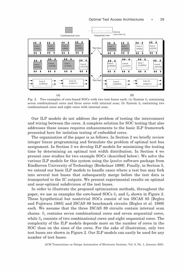
In order to illustrate the proposed optimization methods, throughout thepaper, we use as examples the core-based SOCs S1 and S2 shown in Figure 2.These hyopthetical but nontrivial SOCs consist of ten ISCAS 85 [Brglezand Fujiwara 1985] and ISCAS 89 benchmark circuits [Brglez et al. 1989]each. We assume that the three ISCAS 89 circuits contain internal scanchains. S1 contains seven combinational cores and seven sequential cores,while S2 consists of two combinational cores and eight sequential cores. Thecomplexity of the ILP models depends more on the number of cores in theSOC than on the sizes of the cores. For the sake of illustration, only twotest buses are shown in Figure 2. Our ILP models can easily be used for anynumber of test buses.
Core 1(c432)
Core 2(c499)
Core 3(c880)
Core 4(c1355)
Core 5(c3540)
Core 6(c6288)
Core 7(c7552)
Core 8(s5378)
Core 9(s35932)
Core 10(s38417)
. . .
. . . . . . . . . . . .
. . .. . . . . .
. . .
. . . . . . . . . . . .
. . . . . . . . .
Combinational core Sequential core
Internalscan chain (s)
Test bus 1
Test bus 2
Core 1(c6288)
Core 2(c7552)
Core 3(s838)
Core 4(c9234)
Core 5(s38584)
Core 6(s13207)
Core 7(s15850) Core 8
(s5378)
Core 9(s35932)
Core 10
(s38417)
. . .
. . . . . . . . . . . .
. . .. . . . . .
. . .
. . . . . . . . . . . .
. . . . . . . . .
(a) (b)
Fig. 2. Two examples of core-based SOCs with two test buses each: (a) System S1 containingseven combinational cores and three cores with internal scan; (b) System S2 containing twocombinational cores and eight cores with internal scan.
Optimal Test Access Architectures • 29
ACM Transactions on Design Automation of Electronic Systems, Vol. 6, No. 1, January 2001.

2. OPTIMAL ASSIGNMENT OF CORES TO TEST BUSES
We first briefly review ILP by means of matrix notation [Williams 1985].The goal of ILP is to minimize a linear objective function on a set of integervariables while satisfying a set of linear constraints. A typical ILP model isdescribed as follows:
minimize : Ax
subject to : Bx # C, x $ 0,
where A is a cost vector, B is a constraint matrix, C is a column vector ofconstants, and x is a vector of integer variables. Efficient ILP solvers arenow readily available, both commercially and in the public domain. For ourexperiments (described in Sections 4 and 5), we used the lpsolve packagefrom Eindhoven University of Technology in the Netherlands.
Let the SOC design consist of NC cores and let core i, 1 # i # NC have ni
inputs and mi outputs. We assume that the ni inputs of core i include datainputs and scan inputs. Similarly, the mi outputs of core i include dataoutputs and scan outputs. Each full or partial scan core may have one ormore internal scan chains. (A combinational or nonscan legacy core has noscan inputs and outputs.)
Test data serialization is required at core I/Os when the width of the testbus is less than the number of core terminals [Marinissen et al. 1999]. Thishappens often because the number of core terminals is determined by thefunctionality of the core, while test bus width is determined by the testpattern source, the SOC routing and area constraints and, in some cases,the width of the existing system bus. Therefore, test data serializationmust be performed in the test wrapper if the number of core terminals islarger than the test bus width.
We assume in our serialization model that the test sets for the SOC coresare available in scan format, in which the functional input values remainunchanged during successive scan cycles. (If the test sets for the cores areobtained before the translation to scan format, then alternative serializa-tion models involving the lengths of the scan chains in the cores can beused to reduce the testing time even further.) The amount of test dataserialization necessary at the inputs and outputs of core i is thereforedetermined by its test width f i 5 max$ni, mi%. This influences the testingtime for core i. We assume that core i requires ti (scan) cycles for testing.Finally, we assume that the system contains NB test buses with widthsw1, w2, . . . , wNB.
The problem that we address in this section is to minimize the systemtesting time by optimally assigning cores to test buses. It is formally statedas follows:
● P1: Given NC cores and NB test buses of widths w1, w2, . . . , wNB,respectively, determine an assignment of cores to test buses such thatthe total testing time is minimized.
30 • K. Chakrabarty
ACM Transactions on Design Automation of Electronic Systems, Vol. 6, No. 1, January 2001.
Note that P1 is equivalent to the well-known multiprocessor schedulingproblem, and is therefore NP-complete ([Garey and Johnson 1979, p. 65]).The multiprocessor scheduling problem is stated as follows:
Instance: A finite set A of “tasks,” a ”length” l~a! . 0 for each a [ A, anumber m . 0 of “processors”, and a deadline, D . 0.
Question: Is there a partition A 5 A1 ø A2 ø · · · ø Am of A into mdisjoint sets such that max$Oa[Al~a! : 1 # i # m% # D ?
The equivalence between a decision version of P1 and multiprocessorscheduling can easily be established by noting the correspondence betweenprocessors and test buses and between tasks and test sets. The deadline Dcorresponds to the overall SOC testing time.
Even though P1 is NP-complete, we show that, as in the case of manyother NP-complete problems, it can be solved exactly for practical instancesusing integer linear programming. We assume for now that a test bus doesnot fork (split) into multiple branches that may merge later. This restric-tion is removed in Section 5. We also assume that all cores on any giventest bus are tested sequentially. Two or more test buses can be usedsimultaneously for delivering test data to cores and for propagating testresponses. We assume that the number of test buses (and thereby theamount of test parallelism) is determined by the core user (system integra-tor) after a careful consideration of system-level I/O, area, and powerdissipation issues.
We first note that if core i is assigned to bus j, then the testing time forcore i is given by
Tij 5 H ti if fi # wj
~fi 2 wj 1 1!ti if fi . wj(1)
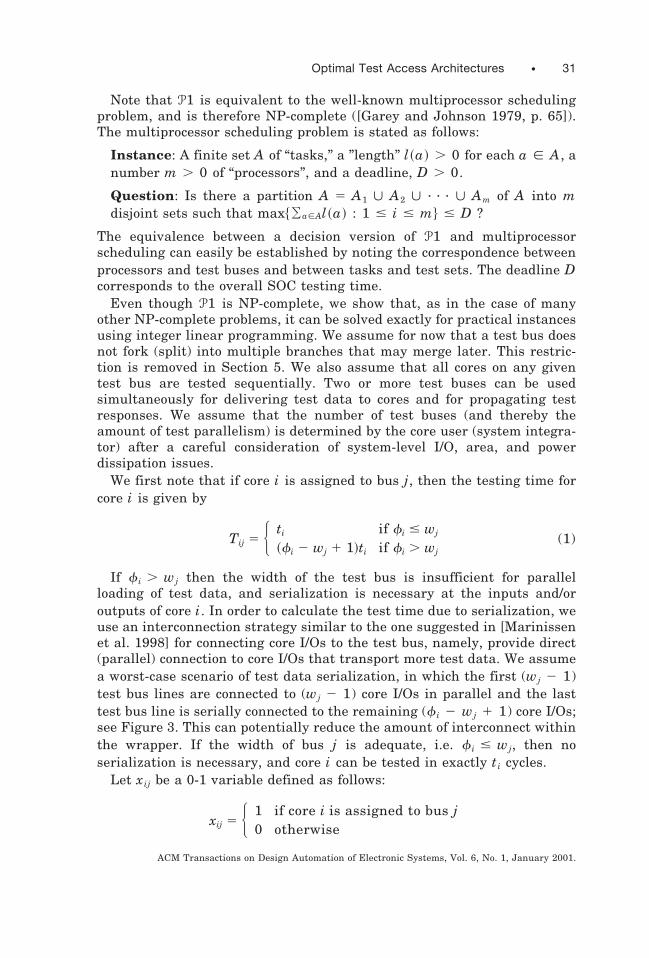
If f i . wj then the width of the test bus is insufficient for parallelloading of test data, and serialization is necessary at the inputs and/oroutputs of core i. In order to calculate the test time due to serialization, weuse an interconnection strategy similar to the one suggested in [Marinissenet al. 1998] for connecting core I/Os to the test bus, namely, provide direct(parallel) connection to core I/Os that transport more test data. We assumea worst-case scenario of test data serialization, in which the first (wj 2 1)test bus lines are connected to (wj 2 1) core I/Os in parallel and the lasttest bus line is serially connected to the remaining (f i 2 wj 1 1) core I/Os;see Figure 3. This can potentially reduce the amount of interconnect withinthe wrapper. If the width of bus j is adequate, i.e. f i # wj, then noserialization is necessary, and core i can be tested in exactly ti cycles.
Let xij be a 0-1 variable defined as follows:
xij 5 H 1 if core i is assigned to bus j0 otherwise
Optimal Test Access Architectures • 31
ACM Transactions on Design Automation of Electronic Systems, Vol. 6, No. 1, January 2001.

The time needed to test all cores on bus j is therefore O i51NC Tijxij. Since all
the test buses can be used simultaneously for testing, the system testingtime equals max
j[$1, 2, . . . NB%O i51
NC Tijxij. We now formulate an integer pro-gramming model for minimizing the system testing time.
Objective: Minimize the cost function C 5 maxj[$1, 2, . . . NB%
O i51NC Tijxij
subject to
(1) O j51NB xij 5 1, 1 # i # NC , 1 # i # NC
(2) xij 5 0 or 1
The above minmax nonlinear cost function can easily be linearized[Williams 1985]. The resulting integer linear programming model is shownin Figure 4. It can be easily seen that the integer linear program ILP modelfor P1 contains NBNC 0-1 variables, one nonbinary, integer variable, andNB 1 NC 1 2NBNC constraint inequalities.
As an example, we consider the SOCs S1 and S2 introduced in Section 1.Table I presents the test data for each embedded core in these systems. Weassume that s838 contains one internal scan chain, and s5378 and s9234contain 4 internal scan chains each. We also assume that s35392 ands38417 contain 32 internal scan chains each, and s13207 and s15850contain 16 scan chains each. For the combinational cores, 1 # i # 7, thenumber of test cycles ti is equal to the number of test patterns pi. However, forthe remaining three cores with internal scan, ti 5 ~ pi 1 1!fi / Ni 1 pi,where core i contains fi flip-flops and ni internal scan chains [Aerts andMarinissen 1998]. The test patterns for these circuits were obtained from[Hamzaoglu and Patel 1998].
Example. Let NB 5 2, and let the total test data width for S1 be 48 bits,i.e. w1 1 w2 5 48. In addition, let w1 5 32 and w2 5 16. The optimal
Core
Test bus
Scan chain
Test bus
Core
Scan chain
Wrapper
Fig. 3. The serialization model.
32 • K. Chakrabarty
ACM Transactions on Design Automation of Electronic Systems, Vol. 6, No. 1, January 2001.

assignment of cores to these two test buses is given by the vector(1,1,1,1,1,1,1,2,2,1), where a 1 (2) in position i of the vector indicates thatcore i is assigned to bus 1 (2). This is shown in Figure 5. The optimaltesting time for these values of w1 and w2 obtained using lpsolve is 411884cycles. Note that this is not the minimum testing time that can be achievedwith a total test width of 48 bits. For example, a testing time of 408077cycles is achieved using w1 5 28, w2 5 20, and the test bus assignmentvector (1,1,2,1,2,1,2,2,2,1). In the next section we examine the problem of
Fig. 4. Integer linear programming model for P1.
Table I. Test Data for Cores in S1 and S2
Number Number Number NumberCircuit of test of test f i 5 of test of test(core) i inputs ni outputs mi max$ni, mi% patterns pi cycles ti
c432 1 36 7 36 27 27c499 2 41 32 41 52 52c880 3 60 26 60 16 16
c1355 4 41 32 41 84 84c3540 5 50 22 50 84 84c6288 6 32 32 32 12 12c7552 7 207 108 207 73 73s5378 8 39 53 53 97 4507
s35932 9 67 352 352 12 714s38417 10 60 138 138 68 3656
(a)
Number Number Number NumberCircuit of test of test f i 5 of test of test(core) i inputs ni outputs mi max$ni, mi% patterns pi cycles ti
c6288 1 32 32 32 12 12c7552 2 207 108 207 73 73s838 3 36 3 36 75 2507
s9234 4 40 43 43 105 5723s38584 5 70 336 336 110 5105s13207 6 78 168 168 234 9634s15850 7 93 166 166 95 3359s5378 8 39 53 53 97 4507
s35932 9 67 352 352 12 714s38417 10 60 138 138 68 3656
(b)
Optimal Test Access Architectures • 33
ACM Transactions on Design Automation of Electronic Systems, Vol. 6, No. 1, January 2001.

determining an optimal distribution of the total test data width among theindividual test buses.
The following theorem presents a lower bound on the total testing timewhen the widths of the test buses are known. This lower bound can indeedbe achieved in practice—we illustrate this below using the system S1 as anexample. We also make use of this theorem in Section 3 to derive a lowerbound on the testing time when only the total test data width is known andthe optimal widths of the test buses have to be determined.
THEOREM 1. For a SOC with NC cores and NB test buses with widthsw1, w2, . . . wNB, respectively, a lower bound on the total testing time T isgiven by T $ max
i$min
j$Tij%% where f i is the test width of core i and Tij is
defined by (1).
PROOF. The testing time for core i depends on the width of the test busto which it is assigned. Clearly, the testing time for core i is at leastmin
j$Tij%. Since the overall system testing time is determined by the core
that has the longest test time, T $ maxi$min
j$Tij%%. e
For the system S1 with two test buses of 32 bits and 16 bits, respectively,Theorem 1 provides a lower bound on the testing time of 391,190 cycles.This corresponds to a test bus assignment in which only core 10 is assignedto the 32-bit first test bus. Such an assignment is indeed optimal and the
Co
re 1
0(s
38
41
7)
Core 1(c432)
Core 2(c499)
Core 3(c880)
Core 4(c1355)
Core 5(c3540)
Core 6(c6288)
Core 7(c7552)
Core 8(s5378)
Core 9(s35932)
Test bus 1
Test bus 2
32
16 3216
Fig. 5. Optimal test bus assignment for system S1 with two test buses of 32 bits and 16 bits,respectively.
34 • K. Chakrabarty
ACM Transactions on Design Automation of Electronic Systems, Vol. 6, No. 1, January 2001.
lower bound of Theorem 1 is achieved if the width of the second test bus isincreased, or if a third test bus is used.
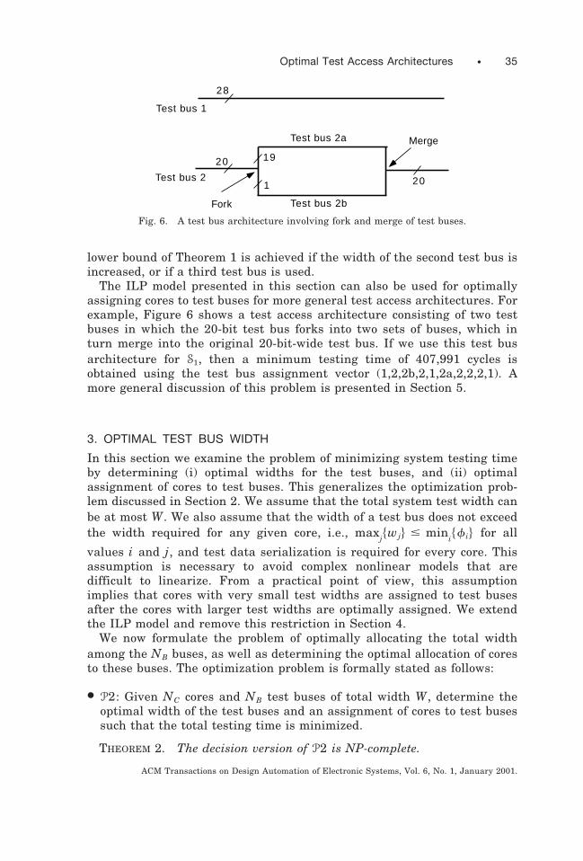
The ILP model presented in this section can also be used for optimallyassigning cores to test buses for more general test access architectures. Forexample, Figure 6 shows a test access architecture consisting of two testbuses in which the 20-bit test bus forks into two sets of buses, which inturn merge into the original 20-bit-wide test bus. If we use this test busarchitecture for S1, then a minimum testing time of 407,991 cycles isobtained using the test bus assignment vector (1,2,2b,2,1,2a,2,2,2,1). Amore general discussion of this problem is presented in Section 5.
3. OPTIMAL TEST BUS WIDTH
In this section we examine the problem of minimizing system testing timeby determining (i) optimal widths for the test buses, and (ii) optimalassignment of cores to test buses. This generalizes the optimization prob-lem discussed in Section 2. We assume that the total system test width canbe at most W. We also assume that the width of a test bus does not exceedthe width required for any given core, i.e., max
j$wj% # min
i$f i% for all
values i and j, and test data serialization is required for every core. Thisassumption is necessary to avoid complex nonlinear models that aredifficult to linearize. From a practical point of view, this assumptionimplies that cores with very small test widths are assigned to test busesafter the cores with larger test widths are optimally assigned. We extendthe ILP model and remove this restriction in Section 4.
We now formulate the problem of optimally allocating the total widthamong the NB buses, as well as determining the optimal allocation of coresto these buses. The optimization problem is formally stated as follows:
● P2: Given NC cores and NB test buses of total width W, determine theoptimal width of the test buses and an assignment of cores to test busessuch that the total testing time is minimized.
THEOREM 2. The decision version of P2 is NP-complete.
28
20 19
1
Test bus 1
Test bus 2
Test bus 2a
Test bus 2bFork
Merge
20
Fig. 6. A test bus architecture involving fork and merge of test buses.
Optimal Test Access Architectures • 35
ACM Transactions on Design Automation of Electronic Systems, Vol. 6, No. 1, January 2001.
PROOF. To show that P2 belongs to NP, we consider the followingdecision problem version of P2: Given NC cores and NB test buses of totalwidth W, does there exist a width distribution for the test buses and anassignment of cores to test buses such that the total testing time is lessthan or equal to T? A nondeterministic algorithm can guess a widthdistribution and a test bus assignment for the cores and check in polyno-mial time if the testing time is less than or equal to T. To show that P2 isNP-hard, we use the method of restriction [Garey and Johnson 1979].Consider an instance of P2 for which the W 5 NBmin
i$f i%. Since the width
of a test bus is at least mini$f i%, this implies that every test bus has a
width of mini$f i%. This is equivalent to an instance of P1 which, as
discussed in Section 2, is NP-complete. Therefore, P2 is NP-hard. e
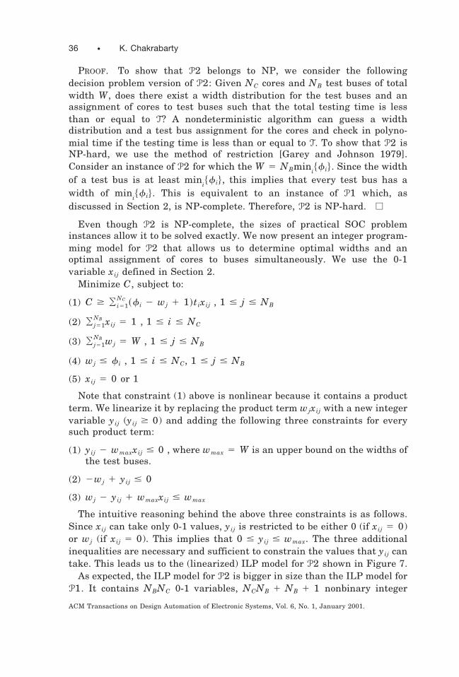
Even though P2 is NP-complete, the sizes of practical SOC probleminstances allow it to be solved exactly. We now present an integer program-ming model for P2 that allows us to determine optimal widths and anoptimal assignment of cores to buses simultaneously. We use the 0-1variable xij defined in Section 2.
Minimize C, subject to:
(1) C $ O i51NC ~f i 2 wj 1 1!tixij , 1 # j # NB
(2) O j51NB xij 5 1 , 1 # i # NC
(3) O j51NB wj 5 W , 1 # j # NB
(4) wj # f i , 1 # i # NC, 1 # j # NB
(5) xij 5 0 or 1
Note that constraint (1) above is nonlinear because it contains a productterm. We linearize it by replacing the product term wjxij with a new integervariable yij (yij $ 0) and adding the following three constraints for everysuch product term:
(1) yij 2 wmaxxij # 0 , where wmax 5 W is an upper bound on the widths ofthe test buses.
(2) 2wj 1 yij # 0
(3) wj 2 yij 1 wmaxxij # wmax
The intuitive reasoning behind the above three constraints is as follows.Since xij can take only 0-1 values, yij is restricted to be either 0 (if xij 5 0)or wj (if xij 5 0). This implies that 0 # yij # wmax. The three additionalinequalities are necessary and sufficient to constrain the values that yij cantake. This leads us to the (linearized) ILP model for P2 shown in Figure 7.
As expected, the ILP model for P2 is bigger in size than the ILP model forP1. It contains NBNC 0-1 variables, NCNB 1 NB 1 1 nonbinary integer
36 • K. Chakrabarty
ACM Transactions on Design Automation of Electronic Systems, Vol. 6, No. 1, January 2001.
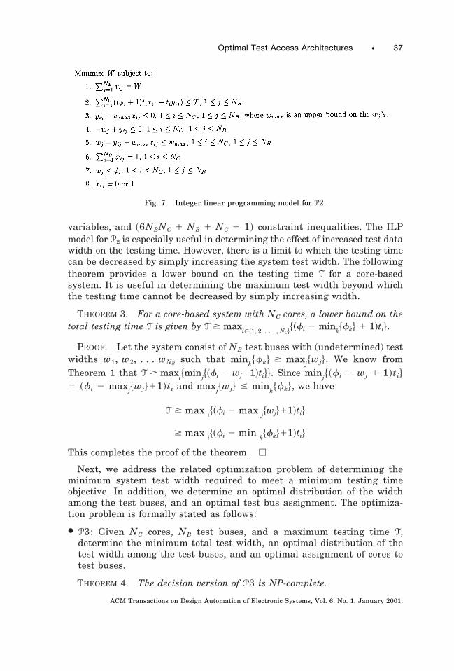
variables, and ~6NBNC 1 NB 1 NC 1 1! constraint inequalities. The ILPmodel for P2 is especially useful in determining the effect of increased test datawidth on the testing time. However, there is a limit to which the testing timecan be decreased by simply increasing the system test width. The followingtheorem provides a lower bound on the testing time T for a core-basedsystem. It is useful in determining the maximum test width beyond whichthe testing time cannot be decreased by simply increasing width.
THEOREM 3. For a core-based system with NC cores, a lower bound on thetotal testing time T is given by T $ max
i[$1, 2, . . . , NC%$~fi 2 min
k$fk% 1 1!ti%.
PROOF. Let the system consist of NB test buses with (undetermined) testwidths w1, w2, . . . wNB such that min
k$fk% $ max
j$wj%. We know from
Theorem 1 that T $ maxi$min
j$~fi 2 wj11!ti%%. Since min
j$~f i 2 wj 1 1!ti%
5 ~f i 2 maxj$wj%11!ti and max
j$wj% # min
k$fk%, we have
T $ maxi$~fi 2 max
j$wj%11!ti%
$ maxi$~fi 2 min
k$fk%11!ti%
This completes the proof of the theorem. e
Next, we address the related optimization problem of determining theminimum system test width required to meet a minimum testing timeobjective. In addition, we determine an optimal distribution of the widthamong the test buses, and an optimal test bus assignment. The optimiza-tion problem is formally stated as follows:
● P3: Given NC cores, NB test buses, and a maximum testing time T,determine the minimum total test width, an optimal distribution of thetest width among the test buses, and an optimal assignment of cores totest buses.
THEOREM 4. The decision version of P3 is NP-complete.
Fig. 7. Integer linear programming model for P2.
Optimal Test Access Architectures • 37
ACM Transactions on Design Automation of Electronic Systems, Vol. 6, No. 1, January 2001.

PROOF. Once again, using the same strategy as in the proof of Theorem2, it is straightforward to show that P3 belongs to NP. To show that P3 isNP-hard, we polynomially transform an arbitrary instance of the knownNP-complete problem P2 to an instance of P3. Consider an instance of P2parameterized by ~NC, NB, W !, with the decision problem version, check-ing if the testing time is less than or equal to T. The corresponding instanceof P3 that we consider is parameterized by ~NC, NB, T!. Suppose a solutionto P3 is obtained in polynomial time with a width of W ,. We now check ifW , # W. This provides a solution in polynomial time for P2. Thus, weconclude that P3 is NP-hard, and therefore NP-complete. e
As in the case of P2, even though P3 is NP-complete, it can be solvedexactly for instances of realistic core-based systems. The ILP model for P3can be derived directly from P2, and is shown in Figure 8. This model is ofthe same size as that for P2, i.e., it has the same number of variables andconstraints. The following theorem relates the width of the widest test busto the minimum testing time T and the test widths of the cores.
THEOREM 5. Let $w1, w2, . . . , wNB% be the optimal width distributionfor a core-based system with NC cores and maximum testing time T. A lowerbound on the width of the widest test bus is given by max
j$wj% $
maxi$f~i! 2 T/ti 1 1%.
PROOF. From the proof of Theorem 3, we know that T $ maxi[$1, 2, . . . , NC%
$~fi 2 maxj$wj%11!ti%. Therefore, f i 2 max
j$wj%11 # T/ti, 1 # i # NC.
This implies that maxj$wj% $ f i 2 T/ti 1 1, 1 # i # NC. e
As examples, consider S1 with two test buses as shown in Figure 2. If anupper bound T 5 430000 cycles is placed on the testing time, thenTheorem 5 yields max
j$wj% 5 22. As demonstrated in Table III, this lower
bound on the test bus width is achieved using the ILP model for P3, henceTheorem 5 provides a tight lower bound.
Fig. 8. Integer linear programming model for P3.
38 • K. Chakrabarty
ACM Transactions on Design Automation of Electronic Systems, Vol. 6, No. 1, January 2001.

4. CASE STUDIES
In this section we present case studies using S1 and S2 for the optimizationproblems P2 and P3. (Solutions for the optimization problem P1 arepresented in Section 2.) We also remove some of the restrictions imposed inSections 2 and 3 in order to simplify the ILP models. We solved the ILPmodels using the lpsolve software package on a Sun Ultra 10 workstationwith a 333 MHz processor and 128 MB memory. We were unable to obtainactual CPU times from lpsolve; however, the user time for P1 is less thanone minute in all cases, while the user time for P2 and P3 is less than onehour in all cases—in fact, in most cases, the CPU time is only a fewminutes. The problem instances, while realistic and representative ofreal-world SOCs, are small enough to be solved exactly using ILP.
Table II presents the optimal test data width, optimal width distribution,and test bus assignment vector when two test buses are considered for S1
and S2. For S1, the lower bound of 391,190 cycles predicted by Theorem 3 isreached for W 5 56 bits. Any further increase in the system test width Wdoes not decrease testing time, since the widest test bus can be at mostmin
i$f i% 5 32 bits. Table III shows the optimal width and width distribu-
tion for S1 and S2 with two test buses for various values of the maximumtesting time T.
In Figure 9, we report experimental data for P2 and P3 when S1 containsthree test buses. As expected, for a given total test width, the testing timewith three buses is less than with two buses; see Figure 9(a). Not surpris-ingly, this difference becomes more pronounced as the total width in-creases. Figure 9(b) shows the total width needed for two and three buses,respectively, for a given maximum testing time T. As T increases, thedifference between the two two cases decreases. This is expected, since lessstringent testing time requirements imply lower width requirements anddecreases the need for more test buses.
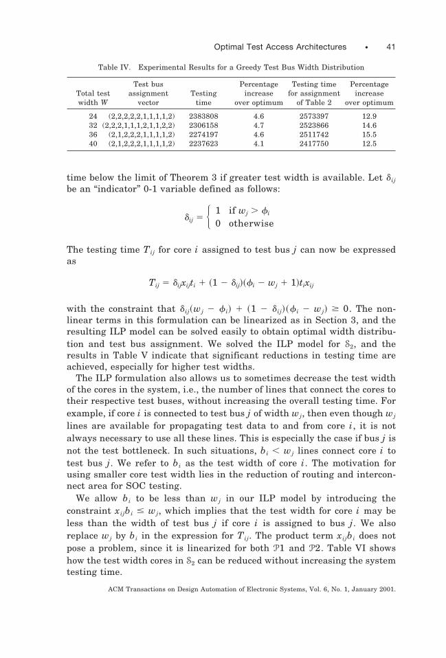
Finally, we present experimental results for S2 when a greedy heuristictest bus design is used. The heuristic divides the total test width W equallyamong the two test buses. In the first set of experiments, we solve P1 todetermine the testing time and an optimal test bus assignment for thisequidistribution. In the second set of experiments, we simply calculate thetesting time using the assignment vector of Table II. Table IV lists thetesting times for various values of W. If P1 is applied to S2 for anequidistribution of W, the testing time increases by 4%. For high-volumeproduction, this increase may translate to substantial incrases in test costs.If the test bus assignment vector of Table II is used, the increase in testingtime is as high as 15%. This motivates the need for an optimal test busdesign approach.
Next, we describe how the ILP models can be extended to remove therestriction max
j$wj% $ min
i$f i%. This is necessary to decrease the testing
Optimal Test Access Architectures • 39
ACM Transactions on Design Automation of Electronic Systems, Vol. 6, No. 1, January 2001.

Table II. Optimum Testing Time and Optimal Width Distribution with Two Test Buses andSystem Test Width for (a) S1 (b) S2
Total test Optimal width Optimum Test bus assignmentwidth W distribution ( w1, w2) testing time vector
8 (4,4) 497200 (2,2,2,1,2,1,2,2,2,1)12 (6,6) 487940 (2,1,2,1,1,1,1,1,1,2)16 (8,8) 478936 (2,2,2,2,2,2,2,2,2,1)20 (11,9) 470380 (2,1,1,2,2,2,2,2,2,1)24 (11,13) 461277 (2,1,1,1,1,1,1,1,1,2)28 (16,12) 452781 (1,2,2,1,2,1,2,2,2,1)32 (18,14) 443620 (2,1,2,2,2,2,2,2,2,1)36 (21,15) 435042 (1,1,2,1,2,1,2,2,2,1)40 (17,23) 426043 (2,2,2,1,1,1,2,1,1,2)44 (25,19) 417057 (2,2,2,2,2,1,2,2,2,1)48 (28,20) 408077 (1,1,2,1,2,1,2,2,2,1)52 (22,30) 399290 (2,2,2,2,2,2,2,2,2,1)56 (32,24) 391190* (2,2,2,2,2,2,2,2,2,1)60 (32,28) 391190* (2,2,2,2,2,2,2,2,2,1)64 (32,32) 391190* (2,2,2,2,2,2,2,2,2,1)
(a)
Total test Optimal width Optimum Test bus assignmentwidth W distribution ( w1, w2) testing time vector
16 (15,1) 2423712 (2,2,2,1,2,1,2,1,1,1)20 (1,19) 2363126 (2,2,1,2,1,2,1,2,2,2)24 (23,1) 2278443 (2,1,1,1,2,1,2,1,1,1)32 (3,29) 2202286 (2,2,2,2,1,2,2,2,2,1)36 (4,32) 2174501 (2,2,2,2,1,2,2,1,1,2)40 (9,31) 2149720 (2,2,2,2,1,2,2,2,2,1)44 (12,32) 2123437 (2,2,2,2,1,2,2,2,2,1)48 (32,16) 2099390 (2,1,1,1,2,1,1,1,1,2)52 (32,20) 2086542 (2,2,1,1,2,1,1,1,1,2)56 (25,31) 2069738 (2,2,2,2,1,2,1,2,2,2)60 (28,32) 2044346 (2,2,2,2,1,2,1,2,2,2)64 (32,32) 2029753 (2,2,1,2,2,1,1,1,1,2)
(b)
*Lower bound on the system testing time (Theorem 3)
Table III. Optimal Width and Width Distribution for S1 with Two Test Buses and aMaximum Testing Time
Maximum testing Optimal test Optimal width Test bus assignmenttime T width W distribution ( w1, w2) vector
400000 52 (21,31) (2,2,2,2,2,2,1,1,1,2)410000 48 (27,21) (2,2,2,2,2,2,2,2,2,1)420000 43 (25,18) (2,2,2,2,1,1,2,2,2,1)430000 39 (22,17) (2,2,2,2,2,2,2,2,2,1)440000 34 (19,15) (2,2,2,2,2,2,2,2,2,1)450000 30 (16,14) (2,2,2,2,2,2,2,2,2,1)460000 25 (14,11) (2,2,2,1,2,2,2,2,2,1)470000 21 (11,10) (2,2,2,2,2,2,2,2,2,1)480000 16 (8,8) (2,2,2,2,2,2,2,2,2,1)
40 • K. Chakrabarty
ACM Transactions on Design Automation of Electronic Systems, Vol. 6, No. 1, January 2001.
time below the limit of Theorem 3 if greater test width is available. Let d ij
be an “indicator” 0-1 variable defined as follows:
dij 5 H 1 if wj . fi
0 otherwise
The testing time Tij for core i assigned to test bus j can now be expressedas
Tij 5 dijxijti 1 ~1 2 dij!~fi 2 wj 1 1!tixij
with the constraint that d ij~wj 2 f i! 1 ~1 2 d ij!~f i 2 wj! $ 0. The non-linear terms in this formulation can be linearized as in Section 3, and theresulting ILP model can be solved easily to obtain optimal width distribu-tion and test bus assignment. We solved the ILP model for S2, and theresults in Table V indicate that significant reductions in testing time areachieved, especially for higher test widths.
The ILP formulation also allows us to sometimes decrease the test widthof the cores in the system, i.e., the number of lines that connect the cores totheir respective test buses, without increasing the overall testing time. Forexample, if core i is connected to test bus j of width wj, then even though wj
lines are available for propagating test data to and from core i, it is notalways necessary to use all these lines. This is especially the case if bus j isnot the test bottleneck. In such situations, bi , wj lines connect core i totest bus j. We refer to bi as the test width of core i. The motivation forusing smaller core test width lies in the reduction of routing and intercon-nect area for SOC testing.
We allow bi to be less than wj in our ILP model by introducing theconstraint xijbi # wj, which implies that the test width for core i may beless than the width of test bus j if core i is assigned to bus j. We alsoreplace wj by bi in the expression for Tij. The product term xijbi does notpose a problem, since it is linearized for both P1 and P2. Table VI showshow the test width cores in S2 can be reduced without increasing the systemtesting time.
Table IV. Experimental Results for a Greedy Test Bus Width Distribution
Test bus Percentage Testing time PercentageTotal test assignment Testing increase for assignment increasewidth W vector time over optimum of Table 2 over optimum
24 (2,2,2,2,2,1,1,1,1,2) 2383808 4.6 2573397 12.932 (2,2,2,1,1,1,2,1,1,2,2) 2306158 4.7 2523866 14.636 (2,1,2,2,2,1,1,1,1,2) 2274197 4.6 2511742 15.540 (2,1,2,2,2,1,1,1,1,2) 2237623 4.1 2417750 12.5
Optimal Test Access Architectures • 41
ACM Transactions on Design Automation of Electronic Systems, Vol. 6, No. 1, January 2001.
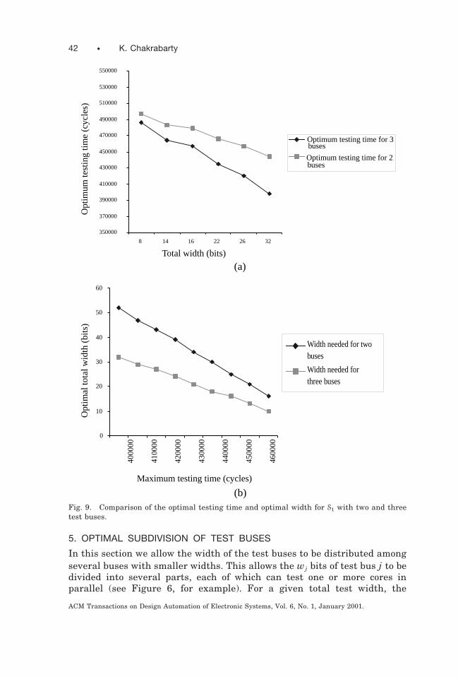
5. OPTIMAL SUBDIVISION OF TEST BUSES
In this section we allow the width of the test buses to be distributed amongseveral buses with smaller widths. This allows the wj bits of test bus j to bedivided into several parts, each of which can test one or more cores inparallel (see Figure 6, for example). For a given total test width, the
350000
370000
390000
410000
430000
450000
470000
490000
510000
530000
550000
8 14 16 22 26 32
buses
buses
Total width (bits)
Opt
imum
test
ing
time
(cyc
les)
Optimum testing time for 2
Optimum testing time for 3
0
10
20
30
40
50
60
Width needed for twobuses
Width needed forthree buses
Maximum testing time (cycles)
Opt
imal
tota
l wid
th (
bits
)
4000
00
4100
00
4200
00
4300
00
4400
00
4500
00
4600
00(a)
(b)Fig. 9. Comparison of the optimal testing time and optimal width for S1 with two and threetest buses.
42 • K. Chakrabarty
ACM Transactions on Design Automation of Electronic Systems, Vol. 6, No. 1, January 2001.
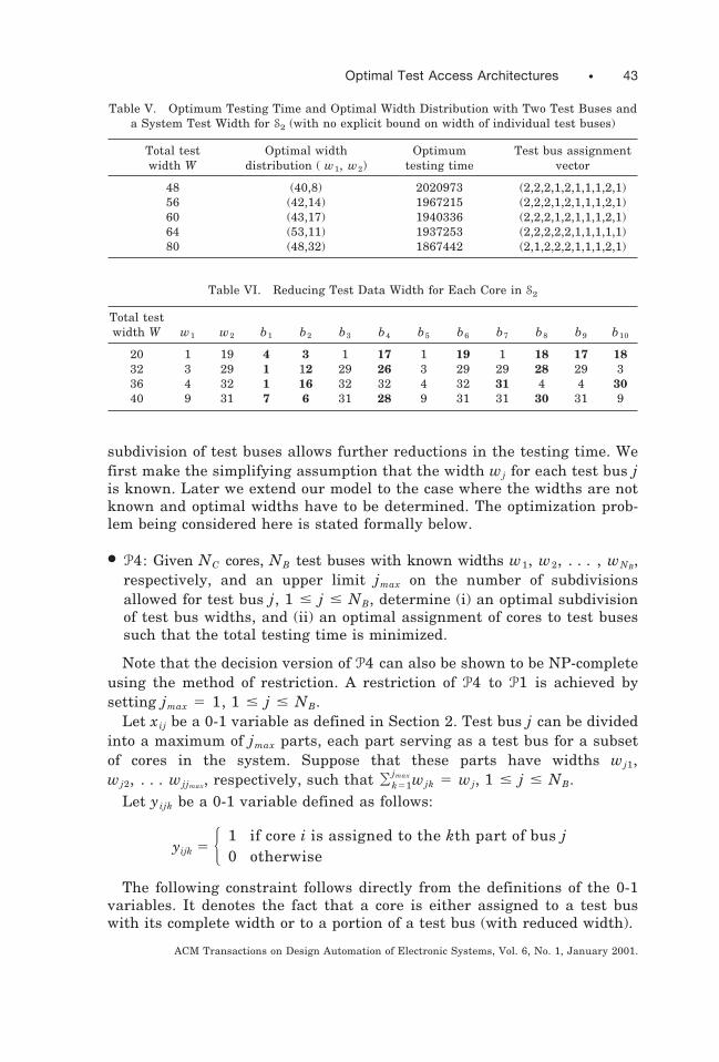
subdivision of test buses allows further reductions in the testing time. Wefirst make the simplifying assumption that the width wj for each test bus jis known. Later we extend our model to the case where the widths are notknown and optimal widths have to be determined. The optimization prob-lem being considered here is stated formally below.
● P4: Given NC cores, NB test buses with known widths w1, w2, . . . , wNB,respectively, and an upper limit jmax on the number of subdivisionsallowed for test bus j, 1 # j # NB, determine (i) an optimal subdivisionof test bus widths, and (ii) an optimal assignment of cores to test busessuch that the total testing time is minimized.
Note that the decision version of P4 can also be shown to be NP-completeusing the method of restriction. A restriction of P4 to P1 is achieved bysetting jmax 5 1, 1 # j # NB.
Let xij be a 0-1 variable as defined in Section 2. Test bus j can be dividedinto a maximum of jmax parts, each part serving as a test bus for a subsetof cores in the system. Suppose that these parts have widths wj1,wj2, . . . wjjmax, respectively, such that Ok51
jmax wjk 5 wj, 1 # j # NB.Let yijk be a 0-1 variable defined as follows:
yijk 5 H 1 if core i is assigned to the kth part of bus j0 otherwise
The following constraint follows directly from the definitions of the 0-1variables. It denotes the fact that a core is either assigned to a test buswith its complete width or to a portion of a test bus (with reduced width).
Table V. Optimum Testing Time and Optimal Width Distribution with Two Test Buses anda System Test Width for S2 (with no explicit bound on width of individual test buses)
Total test Optimal width Optimum Test bus assignmentwidth W distribution ( w1, w2) testing time vector
48 (40,8) 2020973 (2,2,2,1,2,1,1,1,2,1)56 (42,14) 1967215 (2,2,2,1,2,1,1,1,2,1)60 (43,17) 1940336 (2,2,2,1,2,1,1,1,2,1)64 (53,11) 1937253 (2,2,2,2,2,1,1,1,1,1)80 (48,32) 1867442 (2,1,2,2,2,1,1,1,2,1)
Table VI. Reducing Test Data Width for Each Core in S2
Total testwidth W w1 w2 b1 b2 b3 b4 b5 b6 b7 b8 b9 b10
20 1 19 4 3 1 17 1 19 1 18 17 1832 3 29 1 12 29 26 3 29 29 28 29 336 4 32 1 16 32 32 4 32 31 4 4 3040 9 31 7 6 31 28 9 31 31 30 31 9
Optimal Test Access Architectures • 43
ACM Transactions on Design Automation of Electronic Systems, Vol. 6, No. 1, January 2001.

Oj51
NB Ok51
jmax
yijk 1 Oj51
NB
xij 5 1, 1 # i # NC
If core i is assigned the entire width of bus j, then its testing time is~f i 2 wj 1 1!ti. (We assume as before that max
j$wj% # min
i$f i%.) On the
other hand, if it is assigned to the kth test bus derived from bus j, then itstesting time is ~f i 2 wjk 1 1!ti.
The cost function (system testing time) C can now be expressed in termsof the above parameters.
C 5 maxj[$1, 2, . . . , NB%Hmax
k[$1, 2, . . . , jmax%O
i51
NC ~fi 2 wjk 1 1!ti yijk
1 Oi51
NC ~fi 2 wj 1 1!tixijJ.
The right-hand side of the above equation is nonlinear, but it can belinearized as before by a sequence of transformations. Let
C1j 5 maxk[$1, 2, . . . , jmax%
Oi51
NC ~fi 2 wjk 1 1!tiyijk
and C2j 5 O i51NC ~f i 2 wj 1 1!tixij. The cost function can then be expressed
as C 5 maxj[$1, 2, . . . NB%
~C1j 1 C2j! and the optimization problem can beformulated as minimize C, subject to
(1) C $ ~C1j 1 C2j! , 1 # j # NB
(2) Ok51jmax wjk 5 wj , 1 # j # NB
(3) wj # f i , 1 # i # NC, 1 # j # NB
(4) xij 5 0 or 1, 1 # i # NC, 1 # j # NB
(5) yijk 5 0 or 1, 1 # i # NC, 1 # j # NB, 1 # k # jmax
We next linearize constraint (1). Note that C1j $ O i51NC ~f i 2 wjk 1 1!tiyijk
can be linearized by adding a nonbinary, integer variable rijk for each i, j, k,and adding three constraints as in the case of P2 in Section 3. This yieldsthe ILP model for P4 shown in Figure 10. It contains at most NBNC 1NBNCl binary variables, NBNCl 1 NBl 1 2NB 1 1 nonbinary, integervariables, and 5NBNC 1 3NBNC 1 4NB 1 NBl constraint inequalities,where l 5max
j$ jmax%.
We next generalize P4 to the case where the widths of the test buses alsoneed to be optimally determined. The formal statement of this problem isgiven below:
44 • K. Chakrabarty
ACM Transactions on Design Automation of Electronic Systems, Vol. 6, No. 1, January 2001.

● P5: Given NC cores, NB test buses with total width W, and an upper limitjmax on the number of subdivisions allowed for test bus j, 1 # j # NB,determine (i) an optimal width for each test bus, the optimal subdivisionof the width of every test bus, and (ii) an assignment of cores to testbuses such that the total testing time is minimized.
The problem decision version of P5 can also be shown to be NP-completeby restricting it to P2. This is achieved by imposing the restriction jmax 5 1,1 # j # NB. The ILP model for P5, shown in Figure 11, is obtained bycombining the ILP models for P2 and P4. Integer variables sij are intro-duced for linearization. It contains at most NBNC 1 NBNCl binary vari-ables, NBNCl 1 NBl 1 NBNC 1 2NB 1 1 nonbinary integer variables,and 5NBNC 1 6NBNC 1 4NB 1 NBl constraint inequalities, where l 5
maxj$ jmax% as before.
Finally, we present experimental results in solving optimization prob-lems, P4 and P5. We considered S1 and S2 with two test buses (1 and 2), andwe modeled the situation where the first test bus can fork into at most twobranches (1a and 1b). The objective of this set of experiments was twofold:(i) demonstrate that P4 (P5) provides lower testing time than P1 (P2), and(ii) show that even nonoptimal solutions for P5 provide lower testing timethan P2.
Fig. 10. Integer linear programming model for P4.
Optimal Test Access Architectures • 45
ACM Transactions on Design Automation of Electronic Systems, Vol. 6, No. 1, January 2001.
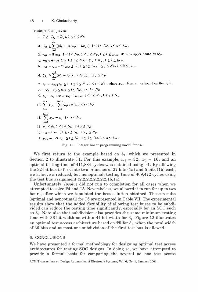
We first return to the example based on S1, which we presented inSection 2 to illustrate P1. For this example, w1 5 32, w2 5 16, and anoptimal testing time of 411,884 cycles was obtained using P1. By allowingthe 32-bit bus to fork into two branches of 27 bits (1a) and 5 bits (1b) each,we achieve a reduced, but nonoptimal, testing time of 409,472 cycles usingthe test bus assignment (2,2,2,2,2,2,2,2,1b,1a).
Unfortunately, lpsolve did not run to completion for all cases when weattempted to solve P4 and P5. Nevertheless, we allowed it to run for up to twohours, after which we tabulated the best solution obtained. These results(optimal and nonoptimal) for P5 are presented in Table VII. The experimentalresults show that the added flexibility of allowing test buses to be subdi-vided can reduce the testing time significantly, especially for an SOC suchas S2. Note also that subdivision also provides the same minimum testingtime with 36-bit width as with a 44-bit width for S1. Figure 12 illustratesan optimal test access architecture based on P5 for S1, when the total widthof 36 bits and at most one subdivision of the first test bus is allowed.
6. CONCLUSIONS
We have presented a formal methodology for designing optimal test accessarchitectures for testing SOC designs. In doing so, we have attempted toprovide a formal basis for comparing the several ad hoc test access
Fig. 11. Integer linear programming model for P5.
46 • K. Chakrabarty
ACM Transactions on Design Automation of Electronic Systems, Vol. 6, No. 1, January 2001.

architectures proposed in the literature. The methodology allows designersto explore design options and make appropriate choices. We examinedseveral problems related to the design of optimal test architectures, including
Table VII. Optimum Testing Time and Optimal Width Distribution with a Total Test DataWidth and Two Test Buses (one forks into two branches): (a) S1 (b) S2
Total testwidth W
Distributionof W:
(w1, w2)Distribution
of w1 Testing time Test bus assignment vector
Improvementover P2
(percent)
20 ( 19,1) (1,18) 441404, (1b,1a,1a,1a,1a,1a,2,2,1a,1b) 6.1624 (23,1) (1,22) 426564, (1b,1a,1a,1a,1a,1a,2,2,1b,1b) 7.5328 (27,1) (26,1) 412427, (1a,1b,1b,1b,1b,1b,2,2,1b,1a) 8.9132 (19,13) (1,18) 441404 (1b,1a,1a,1a,2,1a,2,2,2,1b) 0.5036 (32,4) (31,1) 394012, (1a,1b,1b,1b,1b,1b,2,2,1a,1a) 9.4344 (32,12) (31,1) 394012, (1a,1b,1b,1b,1b,1b,2,2,1b,1a) 5.5352 (22,20) (1,21) 397748 (1b,1a,1a,1a,2,1a,1,1,1a,2) 0.39
(a)
Total testwidth W
Distributionof W:
(w1, w2)Distribution
of w1 Testing time Test bus assignment vector
Improvementover P2
(percent)
24 (23,1) (12,11) 1677735, (1a,1a,1a,1a,1b,1a,2,2,2,2) 23.3636 (28,8) (16,12) 1672265 (1a,1,1a,1a,1b,1a,2,2,2,2) 23.1040 (30,10) (18,12) 1672119 (1a,1,1a,1a,1b,1a,2,2,2,2) 22.2244 (32,12) (17,15) 1633600 (1a,1,1a,1a,1b,1a,2,2,2,2) 23.19
(b)
, Optimum testing time (lpsolve ran to completion)
Core 10(s38417)
Core 1(c432)
Core 2(c499)
Core 3(c880)
Core 4(c1355)
Core 5(c3540)
Core 6(c6288)
Core 7(c7552)
Core 8(s5378)
Core 9(s35932)
Test bus 1 Test bus 2
32
31 1
Test bus 1(out)
(in)
(out)
(in)
4
Test bus 2
1
1
31
32
4
Fig. 12. An optimal test bus architecture for S1 with two test buses, total width of 36 bits,and only one subdivision allowed for the first test bus.
Optimal Test Access Architectures • 47
ACM Transactions on Design Automation of Electronic Systems, Vol. 6, No. 1, January 2001.

assigning cores to test buses, distributing a given test data width amongmultiple test buses, and determining the amount of test data widthrequired to satisfy an upper bound on testing time. We have shown thateven though the decision versions of these design problems are NP-complete, they can be modeled efficiently using integer linear programmingfor practical instances. We applied these models to two nontrivial core-based systems and solved them using a standard software package avail-able in the public domain. We are currently extending the ILP models toincorporate routing and additional power constraints, and recently re-ported initial results in this direction [Chakrabarty 2000b].
Our results give rise to a number of useful extensions and new directionsfor further research, summarized below.● The ILP models need to be generalized to handle test access architec-
tures of the type shown in Figure 1, where a test bus may fork, but notnecessarily merge.
● Test access architectures may also be designed hierachically. Hence, ILPmodels should be able to handle hierarchical compositions, where com-plex cores embed one or more simple cores. Moreover, P4 and P5 shouldbe extended to handle recursive sudivision of the test buses.
● The ILP model descriptions that we have used in our experiments areproblem-specific, i.e., they are described in a format specific to theproblem instance and to the lpsolve program. This is a cumbersomeprocess. It is far more convenient to use high-level languages such asAMPL [Fourer 1993] and GAMS [GAMS Development Corporation 1993]that allow the model to be described in a parameterized form, indepen-dent of the ILP solver and the input data used for a specific instance ofthe model.
● Finally, significant advances have been made in recent years in solvingnonlinear integer programs, and a number of these solvers are nowreadily available, e.g., through the Argonne National Laboratory ,http://www.mcs.anl.gov/otc/Server/neos.html.. We are examining the feasibil-ity of using such nonlinear solvers for designing optimal test accessarchitectures.
ACKNOWLEDGMENTS
The author thanks Erik Jan Marinissen of Philips Research Laboratoriesfor valuable comments on an earlier version of this manuscript.
REFERENCES
AERTS, J. AND MARINISSEN, E. J. 1998. Scan chain design for test time reduction in core-basedICs. In Proceedings of the International Test Conference. IEEE Computer Society Press, LosAlamitos, CA, 448–457.
BERKELAAR, M. 1999. lpsolve, version 2.0. Department of Mathematics and ComputingScience, Eindhoven University of Technology, Eindhoven, Netherlands. E-mail:[email protected]
BRGLEZ, F., BRYANT, D., AND KOZMINSKI, K. 1989. Combinational profiles of sequentialbenchmark circuits. In Proceedings of the IEEE International Symposium on Circuits andSystems (Portland, OR, May). IEEE Press, Piscataway, NJ, 1929–1934.
48 • K. Chakrabarty
ACM Transactions on Design Automation of Electronic Systems, Vol. 6, No. 1, January 2001.
BRGLEZ, F. AND FUJIWARA, H. 1985. A neural netlist of 10 combinational benchmark circuitsand a target translator in Fortran. In Proceedings of IEEE International Symposium onCircuits and Systems. IEEE Computer Society, Washington, DC, 695–698.
CHAKRABARTY, K. 2000a. Test scheduling for core-based systems using mixed-integer linearprogramming. IEEE Trans. Comput.-Aided Des. 19, 10 (Oct.), 1163–1174.
CHAKRABARTY, K. 2000b. Design of system-on-a-chip test access architectures under place-and-route and power constraints. In Proceedings of the Conference on Design Automation(DAC ’2000). ACM Press, New York, NY, 432–437.
CHAKRABARTY, K. 1999. Test scheduling for core-based systems. In Proceedings of Interna-tional Conference on Computer-Aided Design (Nov.). IEEE Computer Society Press, LosAlamitos, CA, 391–394.
FOURER, R., GAY, D. M., AND KERNIGHAN, B. W. 1993. AMPL: A Modeling Language forMathematical Programming. Duxbury Press, Boston, MA.
GAMS DEVELOPMENT CORPORATION. 1993. GAMS: A User’s Guide. Boyd and FraserPublishing Co., Danvers, MA.
GAREY, M. AND JOHNSON, D. 1979. Computers and Intractability: A Guide to the Theory ofNP-Completeness. W. H. Freeman and Co., New York, NY.
GHOSH, I., DEY, S., AND JHA, N. K. 1998. A fast and low cost testing technique for core-basedsystem-on-chip. In Proceedings of the 35th Annual Conference on Design Automation (DAC’98, San Francisco, CA, June 15–19), B. R. Chawla, R. E. Bryant, and J. M. Rabaey,Chairs. ACM Press, New York, NY, 542–547.
GHOSH, I., JHA, N. K., AND DEY, S. 1997. A low overhead design for testability and testgeneration technique for core-based systems. In Proceedings of the International TestConference. IEEE Computer Society Press, Los Alamitos, CA, 50–59.
HAMZAOGLU, I. AND PATEL, J. H. 1998. Test set compaction algorithms for combinationalcircuits. In Proceedings of the 1998 IEEE/ACM International Conference on Computer-Aided Design (ICCAD ’98, San Jose, CA, Nov. 8–12), H. Yasuura, Chair. ACM Press, NewYork, NY, 283–289.
IMMANENI, V. AND RAMAN, S. 1990. Direct access test scheme: Design of block and core cells forembedded ASICs. In Proceedings of the International Test Conference. IEEE ComputerSociety Press, Los Alamitos, CA, 488–492.
MARINISSEN, E. J. AND LOUSBERG, M. 1999. The role of test protocols in testing embedded-core-based system ICs. In Proceedings of the IEEE European Test Workshop. IEEE ComputerSociety Press, Los Alamitos, CA, 70–75.
MARINISSEN, E. J., ZORIAN, Y., KAPUR, R., TAYLOR, T., AND WHETSEL, L. 1999. Towards astandard for embedded core test: An example. In Proceedings of the IEEE International TestConference. IEEE Computer Society Press, Los Alamitos, CA, 616–627.
MARINISSEN, E. J., ARENDSEN, R., BOS, G., DINGEMANSE, H., LOUSBERG, M., AND WOUTERS, C.1998. A structured and scalable mechanism for test access to embedded reusable cores. InProceedings of the International Test Conference. IEEE Computer Society Press, LosAlamitos, CA, 284–293.
SUGIHARA, M., DATE, H., AND YASUURA, H. 1998. A novel test methodology for core-basedsystem LSIs and a testing time minimization problem. In Proceedings of the InternationalTest Conference. IEEE Computer Society Press, Los Alamitos, CA, 465–472.
WILLIAMS, H. P. 1985. Model Building in Mathematical Programming. 2nd ed. John Wiley,New York, NY.
VARMA, P. AND BHATIA, S. 1998. A structured test re-use methodology for core-based systemchips. In Proceedings of the International Test Conference. IEEE Computer Society Press,Los Alamitos, CA, 294–302.
ZORIAN, Y., MARINISSEN, E. J., AND DEY, S. 1998. Testing embedded-core based system chips.In Proceedings of the International Test Conference. IEEE Computer Society Press, LosAlamitos, CA, 130–143.
ZORIAN, Y. 1997. Test requirements for embedded core-based systems and IEEE P1500. InProceedings of the International Test Conference. IEEE Computer Society Press, LosAlamitos, CA, 191–199.
Received: May 1999; accepted: July 2000
Optimal Test Access Architectures • 49
ACM Transactions on Design Automation of Electronic Systems, Vol. 6, No. 1, January 2001.