Direct 3D-printing of phosphate glass by fused deposition ...
Optimal Design Of Fused Deposition Modeling
Structures
using Comsol Multiphysics
Frédéric Roger, Patricia Krawczak
Mines Douai, Département Technologie des Polymères et Composites et Ingénierie Mécanique

Topological optimisation
Step 1
Optimal infill
Step 2
Optimal design and manufacturing strategy for 3d printing
Reduce weight
Optimal stiffness
Interface resistance
and microstructure
Optimal interface resistance
3d printing Heat
transfer modelling
Step 3
Optimal filaments
adhesion
1

Topological optimization: Solid Isotropic Material with Penalization (Bendsoe 1989)
Objective: Minimise weight and maxime stiffness
minimise
10-9≤rp≤1 et p=5
Maximal surface :
0
1
0 0.5 1
E/E0
Step 1 Optimal outer design : topological optimization
2

Topological optimization : Solid Isotropic Material with Penalization
Weak stresses
zone
High stresses zone
Young modulus (Pa) Vmises stresses (Pa)
Step 1 Optimal outer design : topological optimization
3

Optimize manufacturing patterns (inner structure)
with outer optimal geometry
Two materials structure Heterogeneous infill structure
?
Step 2 Optimal infill: heterogeneous infill / multi materials
4

ABS
Filled ABS
With carbon black
Two materials structure with Fused deposition modelling
Interface resitance ?
Manufacturing
Honeycomb structure
Purged walls used
before extruder changing
Step 2 Optimal infill: multi materials
5
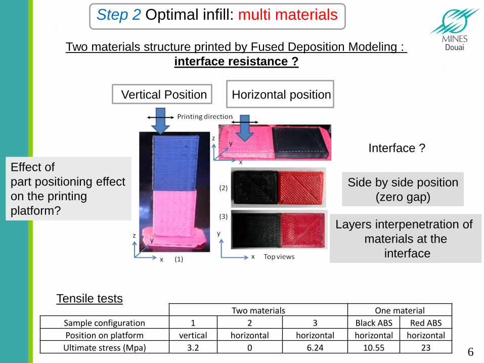
Two materials structure printed by Fused Deposition Modeling :
interface resistance ?
Effect of
part positioning effect
on the printing
platform?
Vertical Position Horizontal position
Side by side position
(zero gap)
Layers interpenetration of
materials at the
interface
Interface ?
Two materials One material
Sample configuration 1 2 3 Black ABS Red ABS
Position on platform vertical horizontal horizontal horizontal horizontal
Ultimate stress (Mpa) 3.2 0 6.24 10.55 23
Tensile tests
Step 2 Optimal infill: multi materials
6

Printing
direction
Two materials structure printed by Fused Deposition Modeling : microstructures?
Step 2 Optimal infill: multi materials
Voids distribution
Voids distribution
7

Optimized part manufacturing (inner structure)
with optimal outer geometry
Rectilinear infill
20%
Rectilinear
infill 60%
Rectilinear
infill 20%
Good adhesion with one material with side by side placed parts
Step 2 Optimal infill: heterogeneous infill
8

Simulation of Fused Deposition Modeling for optimal infill patterns
Infrared thermography
Step 3 FEM modelling : heat transfer
Thermal cycle
?
Adhesion between filament
9

Extract patterns with possible coalescence T>Tref=140°C
Simulation of Fused Deposition Modeling for optimal infill patterns
Step 3 FEM modelling : heat transfer
10

Deposition of 2 circular patterns at 40mm/s et 80mm/s,
droplet (ABS) diameter 200 microns
200 000 degree of freedom155 droplets / circle of radius 5mm,
Finite element activation Heat transfer
Chamber
80°C
Simulation of freeforming (Freeformer Arburg) for optimal infill patterns
Step 3 FEM modelling :
heat transfer with material deposition
11

Conclusion and perpectives:
-Optimal part shape can be obtained by topological optimization
-Optimal Inner structure can improve part resistance :
-Adding a high strength materials in critical areas
-Choosing the right layers orientations
-Increasing infill density in critical areas
-Heat transfer and material deposition modeling can help to find
best infill patterns strategy to maximise filaments adhesion
-Next steps:
-Modeling of filament wetting and adhesion
-Modeling of stresses and strains during and after 3d printing
12

Thank you for your attention
13