Sequential versus Simultaneous Optimal Experimental Design on Dose and Sample times
Contents lists available at ScienceDirect
Tribology International
journal homepage: www.elsevier.com/locate/triboint
Optimal design and experimental verification of fluid dynamic bearings withhigh load capacity applied to an integrated motor propulsor in unmannedunderwater vehicles
Kyobong Kim, Minho Lee, Sangmin Lee, Gunhee Jang⁎
PREM, Graduate school of Hanyang University, 17 Haengdang-dong, Seongdong-gu, Seoul 04763, Republic of Korea
A R T I C L E I N F O
Keywords:Fluid dynamic bearingsIntegrated motor propulsorReynolds equationUnmanned underwater vehicle
A B S T R A C T
We developed fluid dynamic bearings (FDBs) for application in an integrated motor propulsor (IMP) of anunmanned underwater vehicle. The structure of the FDBs is composed of plain and grooved journal and thrustbearings, and sea water is used as the fluid lubricant. The Reynolds equation and their perturbation equationwere solved by applying the finite element method (FEM) to calculate static and dynamic coefficients. Wedeveloped optimal FDBs with high load capacity via an optimization problem of the multi-objective function ofradial and axial load capacities and the constraint equations of friction, stiffness, and damping coefficients.Finally, we prototyped the optimal FDBs with high load capacity and verified the load capacity and frictiontorque of the FDBs via experiments.
1. Introduction
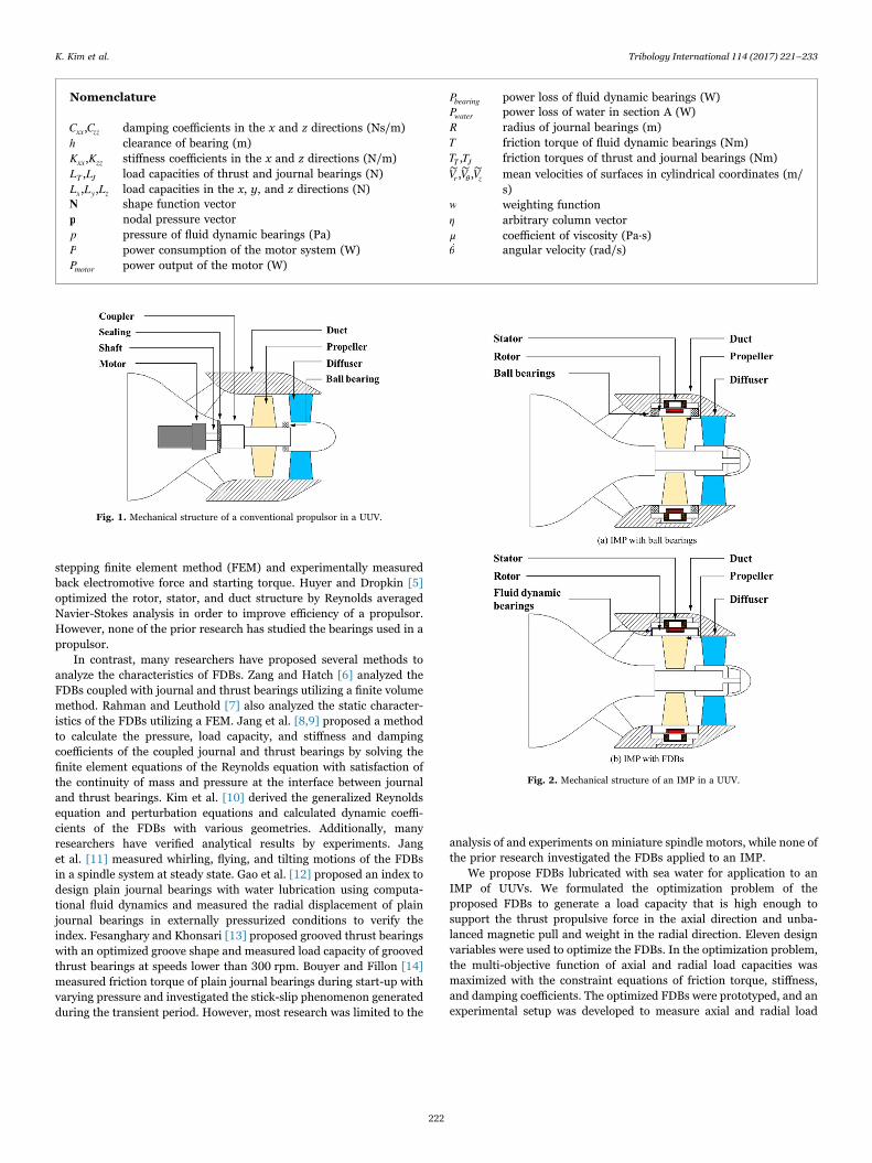
Research on an unmanned underwater vehicle (UUV) has beenconstantly increasing with interest in the investigation and observationof the ocean. One of the key factors in determining the performance ofa UUV is a propulsive system. Fig. 1 shows the mechanical structure ofa conventional propulsor, which consists of a motor, shaft, andpropeller. Power is transmitted from the inboard motor to the outboardpropeller. This system requires cooling of the motor and water-proof-ing due to the complicated mechanical structure of power transmission.In order to resolve these issues, many researchers have made an effortto develop a so-called integrated motor propulsor (IMP), whichcombines a motor with a propulsor. Fig. 2(a) shows a rim-driven typeIMP with ball bearings, in which propellers are directly connected witha rotor of a motor with a large diameter. Since the IMP does not have aconnecting shaft, it has the advantage of compact size and low vibrationand noise. This type of IMP needs sealing that prevents seawater fromflowing into the motor because the ball bearings located between thestator and rotor of motor require an oil lubricant. If the seal isdestroyed, erosion and malfunction of the motor can occur rapidly,especially in a seawater environment. Fluid dynamic bearings (FDBs),which use seawater as a lubricant, can be a good solution, not onlybecause they do not need sealing, but also because they provide betterdynamic performance due to their damping effect. Fig. 2(b) shows themechanical structure of an IMP with FDBs. The FDBs are coupled
journal and thrust bearings, which are composed of thrust bearingssupporting the axial load and journal bearings supporting the radialload. The pressure generated at the FDBs supports the rotating part inboth the radial and axial directions. Since there is no direct contactbetween the metals, the FDBs are superior to ball bearings in terms ofnoise, vibration, and fatigue life. Since the FDBs generate pressure dueto the wedge and groove effects, so their load capacity is relatively lowerthan that of ball. For this reason, FDBs are mostly applied to rotatingsystems with light rotors, such as the spindle motor of computer harddisk drives. However, the FDBs applied to an IMP require high loadcapacity due to the thrust propulsive force in the axial direction andunbalanced magnetic pull and weight in the radial direction.
Not much research on UUVs and IMPs has been published becausethey are mostly used in confidential military applications. Hwang [1]described semi-empirical equations representing the hydrodynamicmodel to calculate loads on the Long Term Mine ReconnaissanceSystem and compared numerical results with those measured from afull-scale model. Jun et al. [2] developed the mechanical, control, andcommunication systems of an autonomous underwater vehicle namedISiMI and investigated speed, open-loop running, closed-loop depth,and a tracking test. Liang et al. [3] designed an IMP with 22.5 kWthrough a field-circuit and electromagnetic thermal coupled model andmeasured back electromotive force and temperature to verify a multi-field coupling method. Liang et al. [4] investigated a solid rotor motorof an IMP by analyzing field-circuit motion coupled with a time-
http://dx.doi.org/10.1016/j.triboint.2017.04.017Received 29 December 2016; Received in revised form 25 March 2017; Accepted 11 April 2017
⁎ Corresponding author.E-mail address: [email protected] (G. Jang).
Tribology International 114 (2017) 221–233
Available online 13 April 20170301-679X/ © 2017 Elsevier Ltd. All rights reserved.
MARK
stepping finite element method (FEM) and experimentally measuredback electromotive force and starting torque. Huyer and Dropkin [5]optimized the rotor, stator, and duct structure by Reynolds averagedNavier-Stokes analysis in order to improve efficiency of a propulsor.However, none of the prior research has studied the bearings used in apropulsor.
In contrast, many researchers have proposed several methods toanalyze the characteristics of FDBs. Zang and Hatch [6] analyzed theFDBs coupled with journal and thrust bearings utilizing a finite volumemethod. Rahman and Leuthold [7] also analyzed the static character-istics of the FDBs utilizing a FEM. Jang et al. [8,9] proposed a methodto calculate the pressure, load capacity, and stiffness and dampingcoefficients of the coupled journal and thrust bearings by solving thefinite element equations of the Reynolds equation with satisfaction ofthe continuity of mass and pressure at the interface between journaland thrust bearings. Kim et al. [10] derived the generalized Reynoldsequation and perturbation equations and calculated dynamic coeffi-cients of the FDBs with various geometries. Additionally, manyresearchers have verified analytical results by experiments. Janget al. [11] measured whirling, flying, and tilting motions of the FDBsin a spindle system at steady state. Gao et al. [12] proposed an index todesign plain journal bearings with water lubrication using computa-tional fluid dynamics and measured the radial displacement of plainjournal bearings in externally pressurized conditions to verify theindex. Fesanghary and Khonsari [13] proposed grooved thrust bearingswith an optimized groove shape and measured load capacity of groovedthrust bearings at speeds lower than 300 rpm. Bouyer and Fillon [14]measured friction torque of plain journal bearings during start-up withvarying pressure and investigated the stick-slip phenomenon generatedduring the transient period. However, most research was limited to the
analysis of and experiments on miniature spindle motors, while none ofthe prior research investigated the FDBs applied to an IMP.
We propose FDBs lubricated with sea water for application to anIMP of UUVs. We formulated the optimization problem of theproposed FDBs to generate a load capacity that is high enough tosupport the thrust propulsive force in the axial direction and unba-lanced magnetic pull and weight in the radial direction. Eleven designvariables were used to optimize the FDBs. In the optimization problem,the multi-objective function of axial and radial load capacities wasmaximized with the constraint equations of friction torque, stiffness,and damping coefficients. The optimized FDBs were prototyped, and anexperimental setup was developed to measure axial and radial load
Nomenclature
Cxx,Czz damping coefficients in the x and z directions (Ns/m)h clearance of bearing (m)Kxx,Kzz stiffness coefficients in the x and z directions (N/m)LT ,LJ load capacities of thrust and journal bearings (N)Lx,Ly,Lz load capacities in the x, y, and z directions (N)N shape function vectorp nodal pressure vectorp pressure of fluid dynamic bearings (Pa)P power consumption of the motor system (W)Pmotor power output of the motor (W)
Pbearing power loss of fluid dynamic bearings (W)Pwater power loss of water in section A (W)R radius of journal bearings (m)T friction torque of fluid dynamic bearings (Nm)TT ,TJ friction torques of thrust and journal bearings (Nm)V∼r ,V
∼θ ,V
∼z mean velocities of surfaces in cylindrical coordinates (m/
s)w weighting functionη arbitrary column vectorμ coefficient of viscosity (Pa∙s)θ ̇ angular velocity (rad/s)
Fig. 1. Mechanical structure of a conventional propulsor in a UUV.
Fig. 2. Mechanical structure of an IMP in a UUV.
K. Kim et al. Tribology International 114 (2017) 221–233
222

capacities according to the variation in axial clearance and eccentricityratio using a three-axis load-cell. Additionally, we measured frictiontorque generated at the FDBs by measuring power consumption atvarious conditions.
2. Method of analysis
2.1. Structure of FDBs for an IMP
Fig. 3 shows the structure of FDBs applied to the rim-driven type ofan IMP. This is composed of upper and lower grooved thrust bearings,upper and lower grooved journal bearings, and a plain journal bearing.Grooves are inscribed on the rotor in which thrust bearings and journalbearings have spiral and herringbone grooves, respectively. Sea water isused as a fluid lubricant flowing through upper grooved thrustbearings, upper grooved journal bearings, plain journal bearings, lowergrooved journal bearings, and lower grooved thrust bearings. Plainjournal bearings are designed between upper and lower groovedjournal bearings, and the width of plain journal bearings correspondsto that of a stator core including coil-winding in order to maintain aconstant air gap between the stator and the rotor.
The proposed FDBs should support external axial and radial forceby generating pressure at the fluid film of the FDBs. External axial forceis thrust force produced by rotation of the propulsor, and it iscalculated to be 3000 N in the case of a 15 knot operating speed fora UUV. External radial forces are the unbalanced magnetic pull andweight of a rotor, and they are set to be 600 N in the case of anunbalanced magnetic pull of 450 N at maximum eccentricity ratio anda rotor weight of 150 N. Accordingly, the objectives for the axial andradial load capacities of the FDBs are established at 3000 N and 600 N,respectively. Table 1 shows the geometry information of the FDBs.Radius and axial length are 210 mm and 190 mm (length of groovedand plain journal bearings) by geometric constraints, respectively. Theradial clearance of grooved journal bearings is 0.5 mm, and the totalclearance of upper and lower grooved thrust bearings is 1 mm.
2.2. Analytical method of FDBs for an IMP
The Reynolds equations for journal and thrust bearings can bewritten as follows [15]:
⎛⎝⎜
⎞⎠⎟
⎛⎝⎜
⎞⎠⎟
⎛⎝⎜
⎞⎠⎟R θ
hμ
pR θ z
hμ
pz
V hR θ
V hz
ht
∂∂ 12
∂∂
+ ∂∂ 12
∂∂
= ∂∂
+ ∂∂
+ ∂∂
∼ ∼θ z
3 3
(1)
⎛⎝⎜
⎞⎠⎟
⎛⎝⎜
⎞⎠⎟
⎛⎝⎜
⎞⎠⎟r r
r hμ
pr r θ
hμ
pr θ
Vr r
rh V hr θ
ht
∂∂ 12
∂∂
+ ∂∂ 12
∂∂
= ∂∂
( ) + ∂∂
+ ∂∂
∼ ∼r θ
3 3
(2)
where R, p, μ, and h are the radius of a journal bearing, pressure,viscosity, and film thickness, respectively. Using by weight function andgeometric boundary condition, the above Reynolds equation can berewritten as weak form as follows:
⎡⎣⎢
⎤⎦⎥
⎡⎣⎢
⎤⎦⎥∫ ∫ ∫h
μw
R θp
R θwz
pz
dA h V wR θ
V wz
dA whdA12
∂∂
∂∂
+ ∂∂
∂∂
= ∂∂
+ ∂∂
− ̇∼ ∼A A
θ zA
3
(3)
⎡⎣⎢
⎤⎦⎥
⎡⎣⎢
⎤⎦⎥∫ ∫ ∫h
μwr
pr
wr θ
pr θ
dA h V wr
V wr θ
dA whdA12
∂∂
∂∂
+ ∂∂
∂∂
= ∂∂
+ ∂∂
− ̇∼ ∼A A
r θA
3
(4)
where w is weighting function. In order to alter weak form of Reynoldsequations as discretized equation, pressure and weight function can beexpressed by shape function N, nodal pressure p, and arbitrary vector η
as follows:
p N p= T (5)
w η N= T (6)
We can obtain discretized equation of Reynolds equation byintroducing Eqs. (5) and (6) into Eqs. (3) and (4) as follows:
⎛⎝⎜⎜
⎡⎣⎢
⎤⎦⎥
⎞⎠⎟⎟
⎡⎣⎢
⎤⎦⎥∫ ∫ ∫h
μ R θ R θ z zdA h V
R θV
zdA hdAN N N N p N N N
12∂∂
∂∂
+ ∂∂
∂∂
= ∂∂
+ ∂∂
− ̇∼ ∼A A
θ zA
T T3
(7)
⎛⎝⎜⎜
⎡⎣⎢
⎤⎦⎥
⎞⎠⎟⎟
⎡⎣⎢
⎤⎦⎥∫ ∫ ∫h
μ r r r θ r θdA h V
rV
r θdA hdAN N N N p N N N
12∂∂
∂∂
+ ∂∂
∂∂
= ∂∂
+ ∂∂
− ̇∼ ∼A A
r θA
T T3
(8)
Discretized equations of Reynolds equation can simplified intoglobal matrix and the pressure at each node can be obtained throughthe FEM [8]. Along the interface between the journal and thrustbearings, the continuity of mass and pressure are automaticallysatisfied by assigning the same number at the nodes between thejournal and thrust bearings. This is because the Reynolds equations ofthe journal and the thrust bearings are actually identical except for theapplied coordinate system. The boundary conditions of the FDBs are
Fig. 3. Structure of the FDBs applied to an IMP.
Table 1Major geometry of FDBs.
Design variable Value
Radius of journal bearing (mm) 210Inner radius of thrust bearing (mm) 178Outer radius of thrust bearing (mm) 210Length of plain journal bearing (mm) 90Length of grooved journal bearing (mm) 50Radial clearance of plain journal bearing (mm) 1Radial clearance of grooved journal bearing (mm) 0.5Total axial clearance of thrust bearing (mm) 1
K. Kim et al. Tribology International 114 (2017) 221–233
223

classified into internal and external boundary conditions. The former isdefined inside the bearing area filled with the fluid lubricant, and thelatter is defined along the geometric boundary exposed to the outerenvironment. The Reynolds boundary condition is applied as theinternal boundary condition to guarantee the continuity of pressureand the pressure gradient across the cavitated area. The iterativemethod is used to satisfy the Reynolds boundary condition.
Once the pressure is determined in the fluid film, the load capacityand the friction torque of FDBs are calculated by integrating thepressure and the shear stress across the fluid film as follows:
∬L pR θdθdz= cosx (9)
∬L pR θdθdz= siny (10)
∬L prdrdθ=z (11)
⎛⎝⎜
⎞⎠⎟∬T h p
R θμ rθ
hR dθdz=
2∂∂
+̇
J2
(12)
⎛⎝⎜
⎞⎠⎟∬T h p
r θμ rθ
hr drdθ=
2∂∂
+̇
T2
(13)
where Lx, Ly, and Lz are the x, y, and z directional load capacities,
respectively, and TJ , and TT are the friction torques of journal and thrustbearings. The total load capacity and friction torque of FDBs aredescribed as follows:
L L L= +J x y2 2
(14)
L L=T z (15)
T T T= +J T (16)
where LJ and LT are the total load capacity of journal and thrustbearings, respectively, and T is the friction torque of FDBs.
Perturbation equations can be derived by the substitution of a first-order expansion of film thickness and pressure with respect to smalldisplacements and velocities into the Reynolds equation [9]. The FEMis applied to solve the pressure change with respect to perturbeddisplacements and velocities with the same boundary conditionsapplied to solve the Reynolds equations. The stiffness and dampingcoefficients of the coupled journal and thrust bearings can be calculatedby integrating the pressure change across the fluid film.
2.3. Finite element model
Fig. 4(a) shows a developed finite element model of FDBs and thedirection of external forces. The fluid film is discretized by 9600isoparametric bilinear elements with four-nodes. The Reynolds bound-ary condition is applied as the internal boundary condition, and zeropressure as the external boundary condition is applied at the upper andlower grooved thrust bearings where seawater flows in and out.Because seawater flows through the FDBs, a pressure difference doesnot exist between flow inlet and outlet of the FDBs, and zero pressureat the flow inlet and outlet is reasonable to describe the externalboundary condition of the FDBs for an IMP. A water viscosity of0.001126 Pa∙s (15 °C) is used in this simulation. The thrust force of3000 N is calculated at the rotor speed of 1000 rpm when themaximum operating speed of a UUV is 15 knots. The maximumunbalanced magnetic pull is calculated to be 450 N when the rotor isin contact with a sleeve (eccentricity ratio =1), and the rotor weightwith a permanent magnet and propeller is calculated to be 150 N.Hence, the required axial and radial load capacities of the FDBs for thisIMP are 3000 N and 600 N, respectively. The developed finite elementmodel was simulated at the various axial and radial clearances to seethat the simulated axial and radial load capacities could reach 3000 Nand 600 N, respectively, given that minimum axial clearance betweenthe upper grooved thrust bearing and sleeve is assumed to be 30 µmduring operating conditions with the consideration of manufacturingand assembly error. Fig. 4(b) shows the pressure distribution of theFDBs in the case of a 30 µm axial clearance and a radial eccentricityratio of 0.62. The maximum pressures at upper grooved thrustbearings, upper grooved journal bearings, and lower grooved thrustbearings are 83.25 kPa, 19.21 kPa, and 12.59 kPa, respectively. Theaxial and radial load capacities are 1236.94 N and 627.90 N, respec-tively. Since the simulated axial load capacity is much smaller than theobjective for axial load capacity (3000 N), optimization of FDBs withrespect to load capacities was performed to meet the requirement.
3. Parametric study and optimization of FDBs
3.1. Parametric study of FDBs
Fig. 5 shows 11 design variables of thrust and journal bearings,which are groove angle, groove depth, and groove to ridge ratio in theupper grooved thrust bearing, groove angle, groove depth, groove to
Fig. 4. Finite element model and pressure distribution of the FDBs.
K. Kim et al. Tribology International 114 (2017) 221–233
224
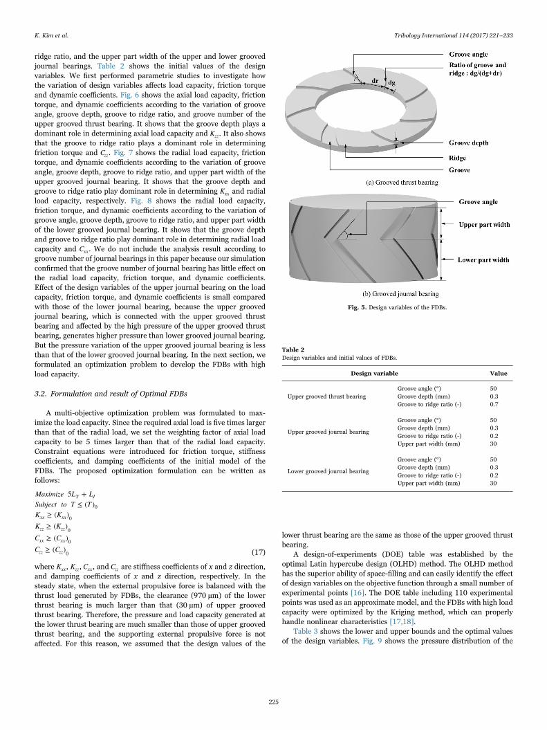
ridge ratio, and the upper part width of the upper and lower groovedjournal bearings. Table 2 shows the initial values of the designvariables. We first performed parametric studies to investigate howthe variation of design variables affects load capacity, friction torqueand dynamic coefficients. Fig. 6 shows the axial load capacity, frictiontorque, and dynamic coefficients according to the variation of grooveangle, groove depth, groove to ridge ratio, and groove number of theupper grooved thrust bearing. It shows that the groove depth plays adominant role in determining axial load capacity and Kzz. It also showsthat the groove to ridge ratio plays a dominant role in determiningfriction torque and Czz. Fig. 7 shows the radial load capacity, frictiontorque, and dynamic coefficients according to the variation of grooveangle, groove depth, groove to ridge ratio, and upper part width of theupper grooved journal bearing. It shows that the groove depth andgroove to ridge ratio play dominant role in determining Kxx and radialload capacity, respectively. Fig. 8 shows the radial load capacity,friction torque, and dynamic coefficients according to the variation ofgroove angle, groove depth, groove to ridge ratio, and upper part widthof the lower grooved journal bearing. It shows that the groove depthand groove to ridge ratio play dominant role in determining radial loadcapacity and Cxx. We do not include the analysis result according togroove number of journal bearings in this paper because our simulationconfirmed that the groove number of journal bearing has little effect onthe radial load capacity, friction torque, and dynamic coefficients.Effect of the design variables of the upper journal bearing on the loadcapacity, friction torque, and dynamic coefficients is small comparedwith those of the lower journal bearing, because the upper groovedjournal bearing, which is connected with the upper grooved thrustbearing and affected by the high pressure of the upper grooved thrustbearing, generates higher pressure than lower grooved journal bearing.But the pressure variation of the upper grooved journal bearing is lessthan that of the lower grooved journal bearing. In the next section, weformulated an optimization problem to develop the FDBs with highload capacity.
3.2. Formulation and result of Optimal FDBs
A multi-objective optimization problem was formulated to max-imize the load capacity. Since the required axial load is five times largerthan that of the radial load, we set the weighting factor of axial loadcapacity to be 5 times larger than that of the radial load capacity.Constraint equations were introduced for friction torque, stiffnesscoefficients, and damping coefficients of the initial model of theFDBs. The proposed optimization formulation can be written asfollows:
Maximize L LSubject to T TK KK KC CC C
5 +≤ ( )
≥ ( )≥ ( )≥ ( )≥ ( )
T J
xx xx
zz zz
xx xx
zz zz
0
0
0
0
0 (17)
where Kxx, Kzz, Cxx, and Czz are stiffness coefficients of x and z direction,and damping coefficients of x and z direction, respectively. In thesteady state, when the external propulsive force is balanced with thethrust load generated by FDBs, the clearance (970 µm) of the lowerthrust bearing is much larger than that (30 µm) of upper groovedthrust bearing. Therefore, the pressure and load capacity generated atthe lower thrust bearing are much smaller than those of upper groovedthrust bearing, and the supporting external propulsive force is notaffected. For this reason, we assumed that the design values of the
lower thrust bearing are the same as those of the upper grooved thrustbearing.
A design-of-experiments (DOE) table was established by theoptimal Latin hypercube design (OLHD) method. The OLHD methodhas the superior ability of space-filling and can easily identify the effectof design variables on the objective function through a small number ofexperimental points [16]. The DOE table including 110 experimentalpoints was used as an approximate model, and the FDBs with high loadcapacity were optimized by the Kriging method, which can properlyhandle nonlinear characteristics [17,18].
Table 3 shows the lower and upper bounds and the optimal valuesof the design variables. Fig. 9 shows the pressure distribution of the
Table 2Design variables and initial values of FDBs.
Design variable Value
Groove angle (°) 50Upper grooved thrust bearing Groove depth (mm) 0.3
Groove to ridge ratio (-) 0.7
Groove angle (°) 50
Upper grooved journal bearingGroove depth (mm) 0.3Groove to ridge ratio (-) 0.2Upper part width (mm) 30
Groove angle (°) 50
Lower grooved journal bearingGroove depth (mm) 0.3Groove to ridge ratio (-) 0.2Upper part width (mm) 30
Fig. 5. Design variables of the FDBs.
K. Kim et al. Tribology International 114 (2017) 221–233
225

Fig. 6. Axial load capacity, friction torque and dynamic coefficients according to the variation of design parameters of the upper grooved thrust bearing. (a) Axial load capacity, frictiontorque and dynamic coefficients according to the variation of groove angle. (b) Axial load capacity, friction torque and dynamic coefficients according to the variation of groove depth. (c)Axial load capacity, friction torque and dynamic coefficients according to the variation of groove number. (d) Axial load capacity, friction torque and dynamic coefficients according to thevariation of groove to ridge ratio.
K. Kim et al. Tribology International 114 (2017) 221–233
226

Fig. 7. Radial load capacity, friction torque and dynamic coefficients according to the variation of design parameters of the upper grooved journal bearing. (a) Radial load capacity,friction torque and dynamic coefficients according to the variation of groove angle. (b) Radial load capacity, friction torque and dynamic coefficients according to the variation of groovedepth. (c) Radial load capacity, friction torque and dynamic coefficients according to the variation of groove to ridge ratio. (d) Radial load capacity, friction torque and dynamiccoefficients according to the variation of upper part width.
K. Kim et al. Tribology International 114 (2017) 221–233
227
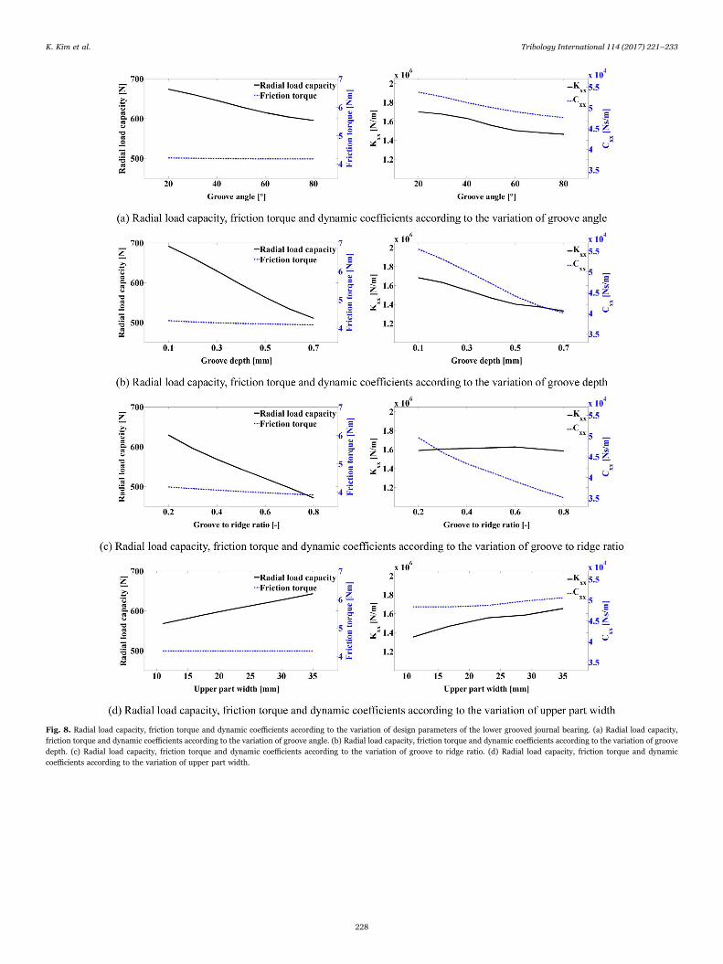
Fig. 8. Radial load capacity, friction torque and dynamic coefficients according to the variation of design parameters of the lower grooved journal bearing. (a) Radial load capacity,friction torque and dynamic coefficients according to the variation of groove angle. (b) Radial load capacity, friction torque and dynamic coefficients according to the variation of groovedepth. (c) Radial load capacity, friction torque and dynamic coefficients according to the variation of groove to ridge ratio. (d) Radial load capacity, friction torque and dynamiccoefficients according to the variation of upper part width.
K. Kim et al. Tribology International 114 (2017) 221–233
228
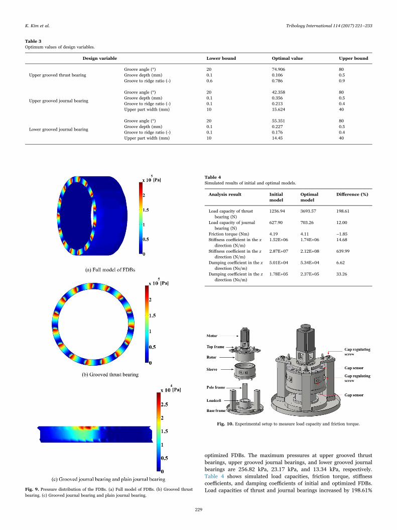
optimized FDBs. The maximum pressures at upper grooved thrustbearings, upper grooved journal bearings, and lower grooved journalbearings are 256.82 kPa, 23.17 kPa, and 13.34 kPa, respectively.Table 4 shows simulated load capacities, friction torque, stiffnesscoefficients, and damping coefficients of initial and optimized FDBs.Load capacities of thrust and journal bearings increased by 198.61%
Table 3Optimum values of design variables.
Design variable Lower bound Optimal value Upper bound
Groove angle (°) 20 74.906 80Upper grooved thrust bearing Groove depth (mm) 0.1 0.106 0.5
Groove to ridge ratio (-) 0.6 0.786 0.9
Groove angle (°) 20 42.358 80
Upper grooved journal bearingGroove depth (mm) 0.1 0.356 0.5Groove to ridge ratio (-) 0.1 0.213 0.4Upper part width (mm) 10 15.624 40
Groove angle (°) 20 55.351 80
Lower grooved journal bearingGroove depth (mm) 0.1 0.227 0.5Groove to ridge ratio (-) 0.1 0.176 0.4Upper part width (mm) 10 14.45 40
Fig. 9. Pressure distribution of the FDBs. (a) Full model of FDBs. (b) Grooved thrustbearing. (c) Grooved journal bearing and plain journal bearing.
Table 4Simulated results of initial and optimal models.
Analysis result Initialmodel
Optimalmodel
Difference (%)
Load capacity of thrustbearing (N)
1236.94 3693.57 198.61
Load capacity of journalbearing (N)
627.90 703.26 12.00
Friction torque (Nm) 4.19 4.11 −1.85Stiffness coefficient in the x
direction (N/m)1.52E+06 1.74E+06 14.68
Stiffness coefficient in the zdirection (N/m)
2.87E+07 2.12E+08 639.99
Damping coefficient in the xdirection (Ns/m)
5.01E+04 5.34E+04 6.62
Damping coefficient in the zdirection (Ns/m)
1.78E+05 2.37E+05 33.26
Fig. 10. Experimental setup to measure load capacity and friction torque.
K. Kim et al. Tribology International 114 (2017) 221–233
229
and 12.00%, respectively. Stiffness and damping coefficients in the xdirection increased by 14.68% and 6.62%, respectively, and those in thez direction increased by 639.99% and 33.26%. Since the clearance of anupper grooved thrust bearing (30 µm) is much smaller than that of agrooved journal bearing (190 µm at the eccentricity ratio of 0.62) atsteady sate, the load capacity and stiffness and damping coefficients inthe z direction increase more significantly than those in x direction.
4. Experimental verification
4.1. Experimental setup
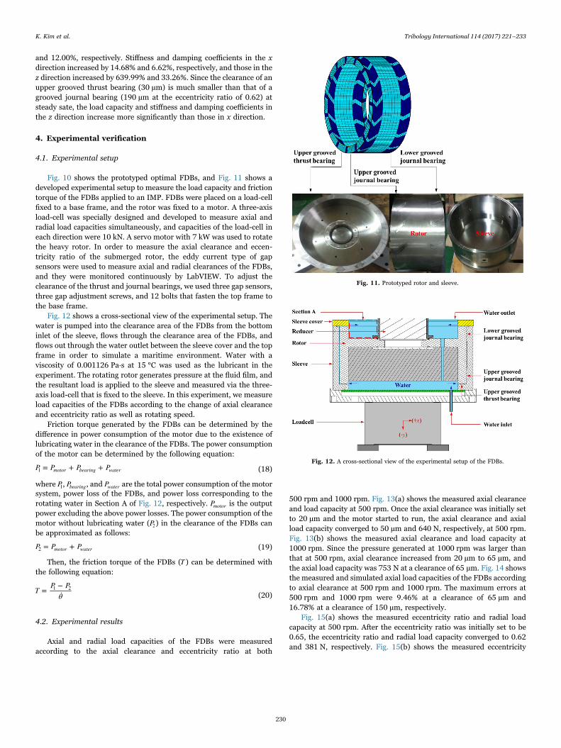
Fig. 10 shows the prototyped optimal FDBs, and Fig. 11 shows adeveloped experimental setup to measure the load capacity and frictiontorque of the FDBs applied to an IMP. FDBs were placed on a load-cellfixed to a base frame, and the rotor was fixed to a motor. A three-axisload-cell was specially designed and developed to measure axial andradial load capacities simultaneously, and capacities of the load-cell ineach direction were 10 kN. A servo motor with 7 kW was used to rotatethe heavy rotor. In order to measure the axial clearance and eccen-tricity ratio of the submerged rotor, the eddy current type of gapsensors were used to measure axial and radial clearances of the FDBs,and they were monitored continuously by LabVIEW. To adjust theclearance of the thrust and journal bearings, we used three gap sensors,three gap adjustment screws, and 12 bolts that fasten the top frame tothe base frame.
Fig. 12 shows a cross-sectional view of the experimental setup. Thewater is pumped into the clearance area of the FDBs from the bottominlet of the sleeve, flows through the clearance area of the FDBs, andflows out through the water outlet between the sleeve cover and the topframe in order to simulate a maritime environment. Water with aviscosity of 0.001126 Pa∙s at 15 °C was used as the lubricant in theexperiment. The rotating rotor generates pressure at the fluid film, andthe resultant load is applied to the sleeve and measured via the three-axis load-cell that is fixed to the sleeve. In this experiment, we measureload capacities of the FDBs according to the change of axial clearanceand eccentricity ratio as well as rotating speed.
Friction torque generated by the FDBs can be determined by thedifference in power consumption of the motor due to the existence oflubricating water in the clearance of the FDBs. The power consumptionof the motor can be determined by the following equation:
P P P P= + +motor bearing water1 (18)
where P1, Pbearing, and Pwater are the total power consumption of the motorsystem, power loss of the FDBs, and power loss corresponding to therotating water in Section A of Fig. 12, respectively. Pmotor is the outputpower excluding the above power losses. The power consumption of themotor without lubricating water (P2) in the clearance of the FDBs canbe approximated as follows:
P P P= +motor water2 (19)
Then, the friction torque of the FDBs (T ) can be determined withthe following equation:
TP P
θ=
−̇
1 2(20)
4.2. Experimental results
Axial and radial load capacities of the FDBs were measuredaccording to the axial clearance and eccentricity ratio at both
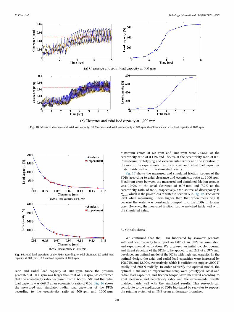
500 rpm and 1000 rpm. Fig. 13(a) shows the measured axial clearanceand load capacity at 500 rpm. Once the axial clearance was initially setto 20 µm and the motor started to run, the axial clearance and axialload capacity converged to 50 µm and 640 N, respectively, at 500 rpm.Fig. 13(b) shows the measured axial clearance and load capacity at1000 rpm. Since the pressure generated at 1000 rpm was larger thanthat at 500 rpm, axial clearance increased from 20 µm to 65 µm, andthe axial load capacity was 753 N at a clearance of 65 µm. Fig. 14 showsthe measured and simulated axial load capacities of the FDBs accordingto axial clearance at 500 rpm and 1000 rpm. The maximum errors at500 rpm and 1000 rpm were 9.46% at a clearance of 65 µm and16.78% at a clearance of 150 µm, respectively.
Fig. 15(a) shows the measured eccentricity ratio and radial loadcapacity at 500 rpm. After the eccentricity ratio was initially set to be0.65, the eccentricity ratio and radial load capacity converged to 0.62and 381 N, respectively. Fig. 15(b) shows the measured eccentricity
Fig. 11. Prototyped rotor and sleeve.
Fig. 12. A cross-sectional view of the experimental setup of the FDBs.
K. Kim et al. Tribology International 114 (2017) 221–233
230
ratio and radial load capacity at 1000 rpm. Since the pressuregenerated at 1000 rpm was larger than that of 500 rpm, we confirmedthat the eccentricity ratio decreased from 0.65 to 0.58, and the radialload capacity was 669 N at an eccentricity ratio of 0.58. Fig. 16 showsthe measured and simulated radial load capacities of the FDBsaccording to the eccentricity ratio at 500 rpm and 1000 rpm.
Maximum errors at 500 rpm and 1000 rpm were 25.56% at theeccentricity ratio of 0.11% and 18.97% at the eccentricity ratio of 0.5.Considering prototyping and experimental errors and the vibration ofthe motor, the experimental results of axial and radial load capacitiesmatch fairly well with the simulated results.
Fig. 17 shows the measured and simulated friction torques of theFDBs according to axial clearance and eccentricity ratio at 1000 rpm.Maximum error between the measured and simulated friction torqueswas 10.9% at the axial clearance of 0.06 mm and 7.2% at theeccentricity ratio of 0.58, respectively. One source of discrepancy isPwater , which is the power loss of water in section A in Fig. 12. The waterlevel when measuring P1 was higher than that when measuring P2because the water was constantly pumped into the FDBs in formercase. However, the measured friction torque matched fairly well withthe simulated value.
5. Conclusions
We confirmed that the FDBs lubricated by seawater generatesufficient load capacity to support an IMP of an UUV via simulationand experimental verification. We proposed an initial coupled journaland thrust structure of the FDBs to be applied to an IMP of a UUV anddeveloped an optimal model of the FDBs with high load capacity. In theoptimal design, the axial and radial load capacities were increased by198.71% and 12.00%, respectively, which is sufficient to support 3000 Naxially and 600 N radially. In order to verify the optimal model, theoptimal FDBs and an experimental setup were prototyped. Axial andradial load capacities and friction torque were measured according toaxial clearance and eccentricity ratio, and the experimental resultsmatched fairly well with the simulated results. This research cancontribute to the application of FDBs lubricated by seawater to supportthe rotating system of an IMP or an underwater propulsor.
Fig. 13. Measured clearance and axial load capacity. (a) Clearance and axial load capacity at 500 rpm. (b) Clearance and axial load capacity at 1000 rpm.
Fig. 14. Axial load capacities of the FDBs according to axial clearance. (a) Axial loadcapacity at 500 rpm. (b) Axial load capacity at 1000 rpm.
K. Kim et al. Tribology International 114 (2017) 221–233
231
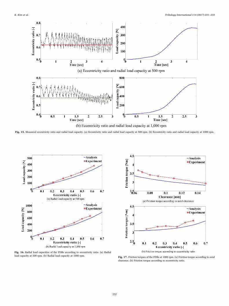
Fig. 15. Measured eccentricity ratio and radial load capacity. (a) Eccentricity ratio and radial load capacity at 500 rpm. (b) Eccentricity ratio and radial load capacity at 1000 rpm.
Fig. 16. Radial load capacities of the FDBs according to eccentricity ratio. (a) Radialload capacity at 500 rpm. (b) Radial load capacity at 1000 rpm. Fig. 17. Friction torques of the FDBs at 1000 rpm. (a) Friction torque according to axial
clearance. (b) Friction torque according to eccentricity ratio.
K. Kim et al. Tribology International 114 (2017) 221–233
232

Acknowledgement
This research was supported the Civil-Military Technology of theNational Research Council of Science & Technology (CMP-13-03-KIMM).
References
[1] Hwang YL. Hydrodynamic modeling of LMRS unmanned underwater vehicle andtow tank test validation. OCEANS 2003;3: pp. 1425–1430.
[2] Jun BH, Park JY, Lee FY, Lee PM, Lee CM, Kim KH, Lim YK, Oh JH. Developmentof the AUV ‘ISiMI’ and a free running test in an ocean engineering basin. Ocean Eng2008;36(1):2–24.
[3] Liang J, Zhang X, Qiao M, Li G. Multifield coupling analysis of integrated motorpropulsor. TELKOMNIKA 2012;10(7):1897–903.
[4] Liang J, Zhang X, Qiao M, Li G. Time-stepping finite element method for integratedmotor propulsor with solid-rotor. J Appl Sci, Eng Technol 2013;5(18):4499–503.
[5] Huyer Dropkin. Integrated motor/propulsor duct optimization for increased vehicleand propulsor performance. J Fluids Eng 2010;133(4):041102–10.
[6] Zang Y, Hatch MR. Analysis of coupled journal and thrust hydrodynamic bearingusing finite volume method. In: Proceedings of the ISPS/ASME, vol. 1. San Jose,CA. P. 71-80; 1995.
[7] Rahman M, Leuthold J. Computer simulation of a coupled journal and thrusthydrodynamic bearing using a finite-element method. In: Proceedings of the 25thAnnual IMCSD Symposium. San Jose, CA. P. 103-112; 1996.
[8] Jang GH, Lee SH. Determination of the dynamic coefficients of the coupled journaland thrust bearings by the perturbation method. Tribol Lett 2006;22(3):239–46.
[9] Jang GH, Lee SH, Kim HW. Finite element analysis of the coupled journal andthrust bearing in a computer hard disk drive. J Tribol: Trans ASME2005;128(2):335–40.
[10] Kim HW, Jang GH, Ha HJ. A generalized Reynolds equation and its perturbationequations for fluid dynamic bearings with curved surfaces. Tribol Int2012;50:6–15.
[11] Jang GH, Oh SH, Lee SH. Experimental study on whirling, flying and tiltingmotions of a 3.5 in. FDB spindle system. Tribol Int 2005;38:675–81.
[12] Gao G, Yin Z, Jing D, Zhang X. Numerical analysis of plain journal bearing underhydrodynamic lubrication by water. Tribol Int 2014;75:31–8.
[13] Fesanghary M, Khonsari MM. On the optimum groove shapes for load-carryingcapacity enhancement in parallel flat surface bearing: theory and experiment.Tribol Int 2013;67:254–62.
[14] Bouyer J, Fillon M. Experimental measurement of the friction torque on hydro-dynamic plain journal bearing during start-up. Tribol Int 2011;44(7–8):772–81.
[15] Hamrock BJ. Fundamentals of Fluid Film Lubrication. New York: McGraw-Hill;1994.
[16] Park JS. Optimal Latin-hypercube designs for computer experiments. J Stat PlanInference 1994;39(1):95–111.
[17] Park PC, Kleijnen. Kriging metamodeling in simulation: A review. EuropeanJournal of Operational Research 2009;192(3): pp. 707–716.
[18] Simpson TW, Mauery TM, Korte JJ. Kriging models for global approximation insimulation-based multidisciplinary design optimization. AIAA J2001;39(12):2233–41.
K. Kim et al. Tribology International 114 (2017) 221–233
233