Optical theorem in atomic physics and wave power
4
Optical theorem in atomic physics and wave power F.J.M. Farley * Department of Electrical and Electronic Engineering, Trinity College, Dublin [email protected] In atomic physics, when a plane wave of amplitude 1 interacts with an atom or nucleus, the amplitude at distance R and angle θ is taken as A(θ) = (1/kR)f (θ) (1) where k =2π/λ and f (θ) is called the scattering amplitude. For real f the radiation is in phase with the incident wave. The “optical theorem” states that the total cross-section (i.e. the effective combined target area for scattering and capture) is σ tot =4πλ - 2 {f (0)} (2) with λ - = λ/2π. Figure 1: Fraunhofer spiral To understand this formula, consider a plane of atoms transverse to the incoming wave, as shown in Fig. 1, with n atoms/cm 2 , and sum over the wavelets reaching point P on the axis from annular elements of radius y to y + dy, using the Fraunhofer spiral. The phase delay for this annulus, relative to the wave from the centre, is θ = πy 2 /Rλ, while the elementary vector at P corresponding to this annulus has length dV =2πydy × nf (0)/kR. As dθ ∝ dV , the vectors add to a circle of radius AB = dV /dθ =2πnλ - 2 f (0). If P is far from the plane of atoms, only the forward scattering amplitude f (0) is relevant. The elements far from the axis contribute gradually less and less (because of their increasing distance from P) so adding over the whole plane gives a slowly diminishing spiral and the final vector is just the * Address for correspondence: 8 Chemin de Saint Pierre, 06620 le Bar sur Loup, France
Transcript of Optical theorem in atomic physics and wave power

Optical theorem in atomic physics and wave power
F.J.M. Farley∗
Department of Electrical and Electronic Engineering, Trinity College, Dublin
In atomic physics, when a plane wave of amplitude 1 interacts with an atom or nucleus, the amplitudeat distance R and angle θ is taken as
A(θ) = (1/kR)f(θ) (1)
where k = 2π/λ and f(θ) is called the scattering amplitude. For real f the radiation is in phase withthe incident wave. The “optical theorem” states that the total cross-section (i.e. the effective combinedtarget area for scattering and capture) is
σtot = 4πλ-2 ={f(0)} (2)
with λ- = λ/2π.
Figure 1: Fraunhofer spiral
To understand this formula, consider a plane of atoms transverse to the incoming wave, as shownin Fig. 1, with n atoms/cm2, and sum over the wavelets reaching point P on the axis from annularelements of radius y to y + dy, using the Fraunhofer spiral. The phase delay for this annulus, relativeto the wave from the centre, is θ = πy2/Rλ, while the elementary vector at P corresponding to thisannulus has length dV = 2πydy × nf(0)/kR. As dθ ∝ dV , the vectors add to a circle of radiusAB = dV/dθ = 2πnλ-2
f(0).
If P is far from the plane of atoms, only the forward scattering amplitude f(0) is relevant. Theelements far from the axis contribute gradually less and less (because of their increasing distance fromP) so adding over the whole plane gives a slowly diminishing spiral and the final vector is just the
∗Address for correspondence: 8 Chemin de Saint Pierre, 06620 le Bar sur Loup, France
1

vector AB of length 2πnλ-2f(0). The vital point is that although all the atoms radiate in phase with the
incoming wave, the vector AB is delayed 90o relative to the original wave at P , because on average thepath length to P is slightly increased. Adding AB to the original vector OA of length 1, the resultantOB is slightly delayed in phase. This is the origin of refractive index.
If there are ρ, atoms per cm3 and the layer of atoms is t
Figure 2: η circle, radius 1
thick, the phase shift is
(µ− 1)t/λ = 2πλ-2f(0)ρt
soµ− 1 = 4π2ρλ-3
f(0)
is determined by the real part of the forward scatteringamplitude. This tells us how to make refracting lenses inthe sea, using a field of undamped resonant scatterers!
If f(0) is imaginary we get an extra phase shift of 90o
and the vector AB subtracts from the incoming vectorOA: the wave is attenuated. For small n,
OB2 = {1− 2πnλ-2 ={f(0)}}2 = 1− nσtot
where σtot is the total cross-section per atom for interac-tion with the incoming wave: Eqn.(1) follows.
σtot is the effective area for one atom interacting with the incoming wave; it includes scattering andcapture.
σtot = σscat + σcap.
If the size of the interacting body is much less than λ, the scattered amplitude is isotropic and we canwrite f = 1
2i(1− η). Then
σtot = 2πλ-2 <{1− η} (3)
But by integrating (1) over the whole solid angle 4π,
σscat = 4πλ-2f 2 = πλ-2|1− η|2 (4)
soσcap = σtot − σscat = πλ-2
(1− |η|2) (5)
From this we conclude that |η| ≤ 1. Fig. 2 shows the circle in the complex plane which includes allpossible values of η. If η is represented by the point Y , the shaded area is proportional to σcap. Thesquare of the vector XY determines σscat, while twice its horizontal projection gives σtot. Maximumpower is captured when η = 0 and in this case σcap = σscat = 1
2σtot.
For water waves in two dimensions, similar arguments apply. Consider an incoming plane wave ofunit amplitude incident on a line of objects, n per unit length, each radiating an amplitude
A(θ) = (λ/R)1/2f(θ) (6)
As before the phase delay for a signal from Q (fig. 1) is πy2/Rλ = πv2/2 where v = y√
2/Rλ while thelength of the elementary vector at P corresponding to the line element dy at Q is
n(λ/R)1/2f(θ)√
Rλ/2 dv = nλf(0)dv/√
2.
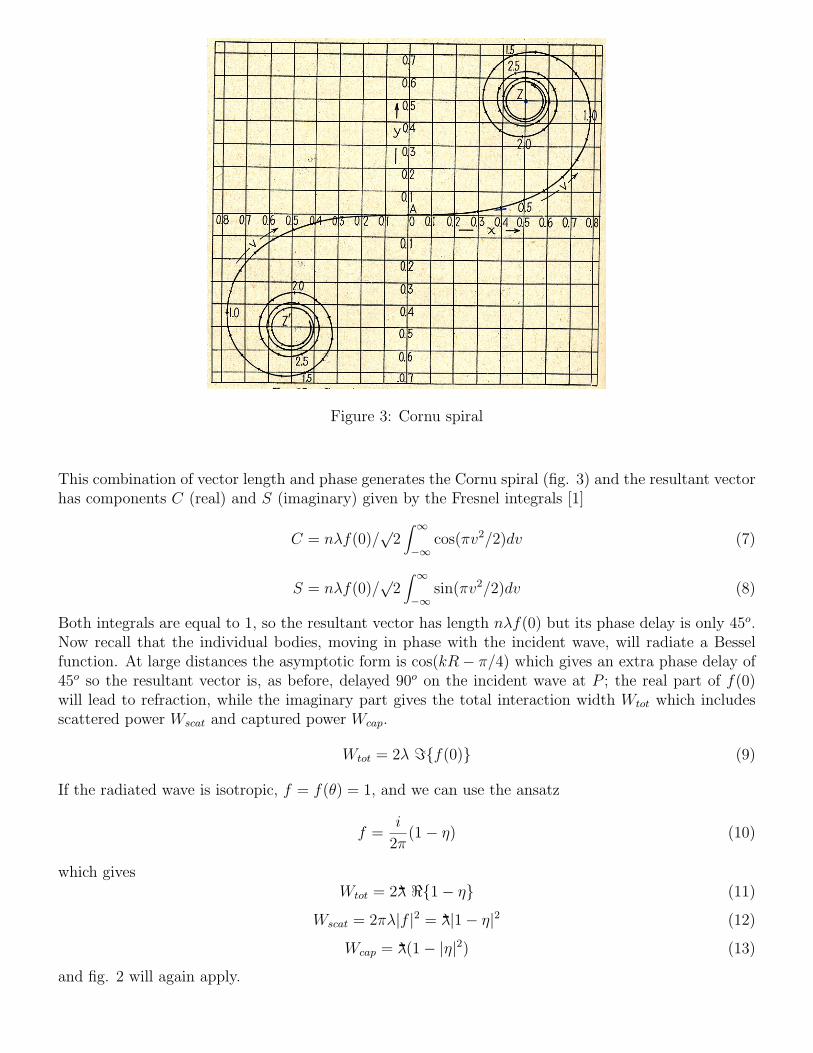
Figure 3: Cornu spiral
This combination of vector length and phase generates the Cornu spiral (fig. 3) and the resultant vectorhas components C (real) and S (imaginary) given by the Fresnel integrals [1]
C = nλf(0)/√
2∫ ∞−∞
cos(πv2/2)dv (7)
S = nλf(0)/√
2∫ ∞−∞
sin(πv2/2)dv (8)
Both integrals are equal to 1, so the resultant vector has length nλf(0) but its phase delay is only 45o.Now recall that the individual bodies, moving in phase with the incident wave, will radiate a Besselfunction. At large distances the asymptotic form is cos(kR− π/4) which gives an extra phase delay of45o so the resultant vector is, as before, delayed 90o on the incident wave at P ; the real part of f(0)will lead to refraction, while the imaginary part gives the total interaction width Wtot which includesscattered power Wscat and captured power Wcap.
Wtot = 2λ ={f(0)} (9)
If the radiated wave is isotropic, f = f(θ) = 1, and we can use the ansatz
f =i
2π(1− η) (10)
which givesWtot = 2λ- <{1− η} (11)
Wscat = 2πλ|f |2 = λ-|1− η|2 (12)
Wcap = λ-(1− |η|2) (13)
and fig. 2 will again apply.

More generally, when the polar diagram is not isotropic,
Wscat = λ∫ 2π
0|f(θ)|2 dθ (14)
and subtracting this from eqn(9) gives
Wcap = 2λ ={f(0)} − λ∫ 2π
0|f(θ)|2 dθ (15)
Note that f(θ) enters linearly in the first term and squared in the second, so by varying the magnitudeof f(θ) keeping the same functional form, Wcap can be maximized and the optimum value is
Wmaxcap = λ
[={f(0)}]2∫ 2π0 |f(θ)|2 dθ
(16)
This formula has been found independently for particular cases by Newman [2] and Evans [3]. Themore general result was derived by Farley [4]. Eqn(16) is completely independent of the mechanismof wave capture and applies to any combination of vibrational modes in the device; the capture widthdepends only on the polar diagram and the phase of the radiated waves.
For example, for a small heaving buoy the radiation is isotropic, f0(θ) = 1, and the best capturewidth is λ/2π [5]. For a small object moving in surge or pitch however f1(θ) = cos(θ) and the capturewidth rises to 2× λ/2π. One may combine these modes to give
f(θ) = f0(θ) + βf1(θ)
and vary β to get the best result; one finds β = 2 which gives Wcap = 3 × λ/2π in agreement withFalnes [6].
It is clear from eqn(16) that an ideal attenuator should radiate only in the forward direction. Themore concentrated the polar diagram, the greater the capture width. But antenna theory tells us thatto have a narrow polar diagram, the radiator must be several wavelengths long, either in the beamdirection or transverse to it. Furthermore, to concentrate the beam in the forward direction a travelingwave should be excited on the attenuator.
References
[1] See for example F.A. Jenkins and H.E. White, Fundamentals of Physical Optics, McGraw-Hill(1937), p. 185ff
[2] J.N. Newman, Applied Ocean Research 1, 189 (1979)
[3] D.V.Evans, Symp. Wave Energy Utilization, Gothenberg (1979)
[4] F.J.M. Farley, Applied Ocean Research 4, 62 (1982)
[5] K. Budal and J. Falnes, Nature 256, 478 (1975)
[6] J. Falnes, Ocean Waves and Oscillating Systems, Camb. Univ. Press 2002, p. 216, 217