Creating Maps Using Coordinate Grids A Coordinate Grid Project.
* [email protected], Tel. (301)286-7864
Optical testing using portable laser coordinate measuring instruments Manal Khreishi*a, Raymond G. Ohla, Kyle F. Mcleana, Theodore J. Hadjimichaela, Joseph E.
Haydenb
aNASA Goddard Space Flight Center, 8800 Greenbelt Road, Greenbelt, MD, USA 20771 bSigma Space Corporation, 4600 Forbes Blvd, Lanham, MD 20706
ABSTRACT
High precision, portable coordinate measuring instruments (CMI) such as laser radars (LR) and laser trackers (LT) have
been used for optical system alignment and integration. The LR’s ability to perform a non-contact scan of surfaces was
previously utilized to characterize large spherical and aspheric mirrors. In this paper, we explore the use of a CMI as an
accurate, fast, robust, and non-contact tool for prescription characterization of powered optical surfaces. Using Nikon’s
MV-224/350 LR and Leica’s Absolute Tracker AT401/402 instruments, proof of concept measurements were performed
to characterize a variety of optical components by measuring the actual and apparent, or equivalently the “direct and
through” (D&T), coordinates of calibrated metrology targets. Custom macros in metrology software and other data
reduction code were developed to compute surface-ray intercepts and surface slopes from the D&T shots. The calculated
data is fit to an aspheric surface formula to obtain the optimum prescription. The results were compared to the nominal
parameters and were crosschecked using LR scans or other approaches. We discuss potential applications across the
fields of optical component fabrication and system alignment and testing.
Keywords: Optical testing, optical metrology, prescription characterization, laser radar, laser tracker, direct and through
measurement, laser coordinate measuring instrument
1. INTRODUCTION
Laser radars and laser trackers are portable Coordinate Measurement Machine (CMM)-like instruments that are
becoming increasingly advanced and relatively less expensive. These high precision and versatile spherical-measurement
devices are mainly utilized for mechanical/dimensional metrology, particularly large-volume, and alignment
applications. In recent years, more interest developed in the use of LTs and LRs for optical shop applications.
LTs were used to guide the figuring of large mirrors, such as the Giant Magellan Telescope (GMT) and the Large
Synoptic Survey Telescope (LSST) primary mirrors (PM), to an accuracy that would allow optical testing1. Zobrist2 and
Gallagher3 evaluated the use of LTs for a number of optical shop applications. A Laser Tracker Plus system developed
by Zobrist, where an LT is coupled with an advanced calibration technique, not only served to guide the large mirror
fabrication process, but was also used as a verification test for the GMT-PM#1 principal interferometric test to
corroborate the measurements in several low-order aberrations. In addition, Zobrist employed an LT to define the
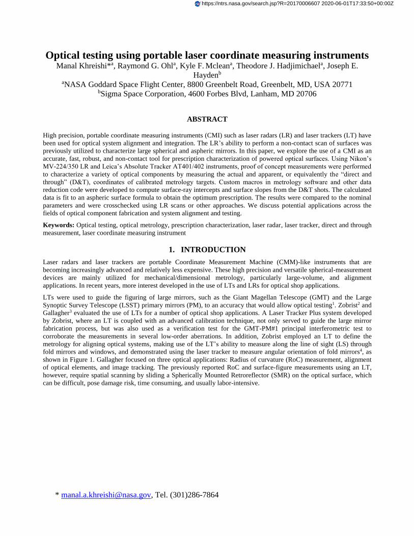
metrology for aligning optical systems, making use of the LT’s ability to measure along the line of sight (LS) through
fold mirrors and windows, and demonstrated using the laser tracker to measure angular orientation of fold mirrors4, as
shown in Figure 1. Gallagher focused on three optical applications: Radius of curvature (RoC) measurement, alignment
of optical elements, and image tracking. The previously reported RoC and surface-figure measurements using an LT,
however, require spatial scanning by sliding a Spherically Mounted Retroreflector (SMR) on the optical surface, which
can be difficult, pose damage risk, time consuming, and usually labor-intensive.
https://ntrs.nasa.gov/search.jsp?R=20170006607 2020-06-01T17:33:50+00:00Z
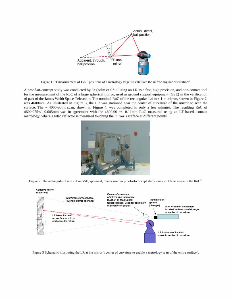
Figure 1 LT measurement of D&T positions of a metrology target to calculate the mirror angular orientation4.
A proof-of-concept study was conducted by Eegholm et al5 utilizing an LR as a fast, high precision, and non-contact tool
for the measurement of the RoC of a large spherical mirror, used as ground support equipment (GSE) in the verification
of part of the James Webb Space Telescope. The nominal RoC of the rectangular 1.4 m x 1 m mirror, shown in Figure 2,
was 4600mm. As illustrated in Figure 3, the LR was stationed near the center of curvature of the mirror to scan the
surface. The ~ 4000-point scan, shown in Figure 4, was completed in only a few minutes. The resulting RoC of
4600.075+/- 0.005mm was in agreement with the 4600.00 +/- 0.11mm RoC measured using an LT-based, contact
metrology, where a retro reflector is measured touching the mirror’s surface at different points.
Figure 2 The rectangular 1.4 m x 1 m GSE, spherical, mirror used in proof-of-concept study using an LR to measure the RoC5.
Figure 3 Schematic illustrating the LR at the mirror’s center of curvature to enable a metrology scan of the entire surface5.
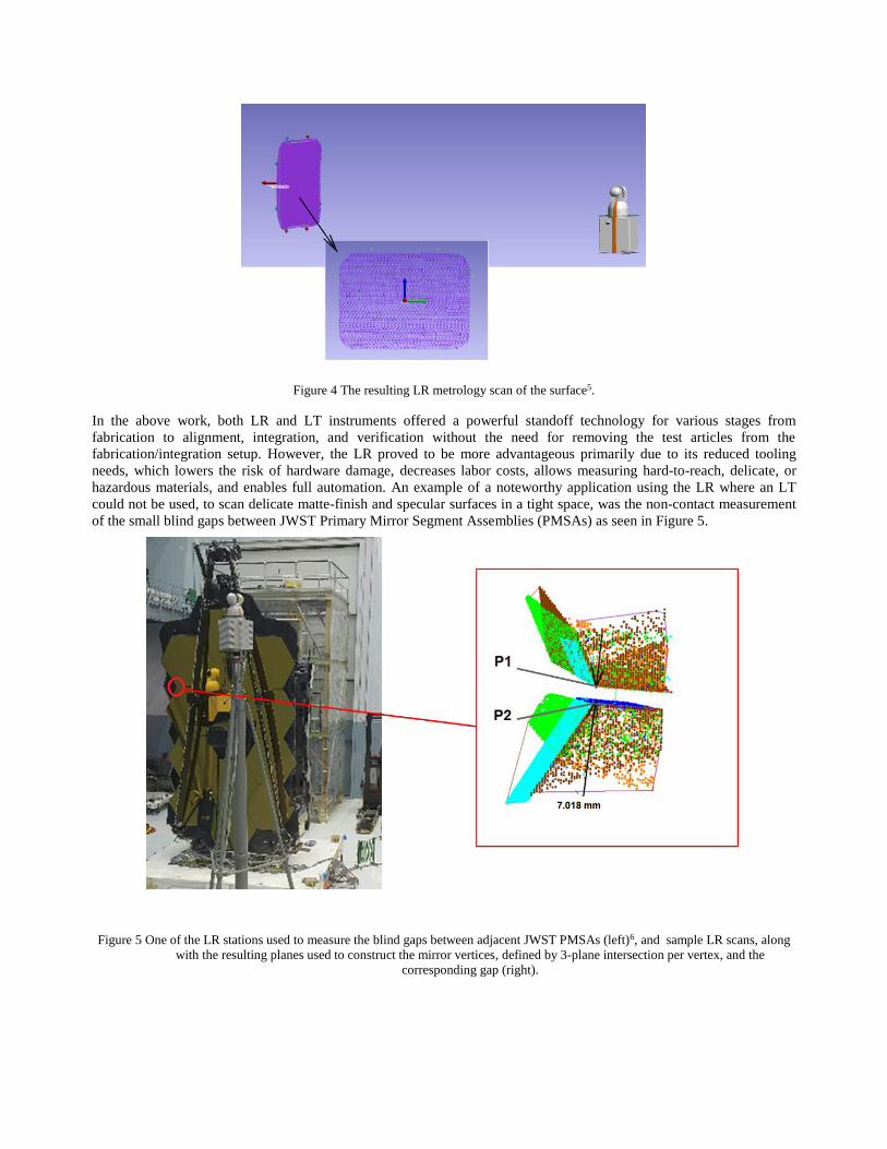
Figure 4 The resulting LR metrology scan of the surface5.
In the above work, both LR and LT instruments offered a powerful standoff technology for various stages from
fabrication to alignment, integration, and verification without the need for removing the test articles from the
fabrication/integration setup. However, the LR proved to be more advantageous primarily due to its reduced tooling
needs, which lowers the risk of hardware damage, decreases labor costs, allows measuring hard-to-reach, delicate, or
hazardous materials, and enables full automation. An example of a noteworthy application using the LR where an LT
could not be used, to scan delicate matte-finish and specular surfaces in a tight space, was the non-contact measurement
of the small blind gaps between JWST Primary Mirror Segment Assemblies (PMSAs) as seen in Figure 5.
Figure 5 One of the LR stations used to measure the blind gaps between adjacent JWST PMSAs (left)6, and sample LR scans, along
with the resulting planes used to construct the mirror vertices, defined by 3-plane intersection per vertex, and the
corresponding gap (right).
In section 2 of this paper, we introduce the CMIs, MV-224/350 and AT402, and describe the calibrated metrology target
used for the generalized D&T proof-of-concept (PoC) study. D&T data collection for the cases of an off-axis-parabolic
(OAP) and a convex sphere is detailed in section 3. The analysis and results, RoC and conic coefficient, are discussed in
section 4. The conclusion at the end of this paper includes a summary of the PoC study and the near future work plans.
2. INSTRUMENTS AND TARGETS
2.1 Laser radar
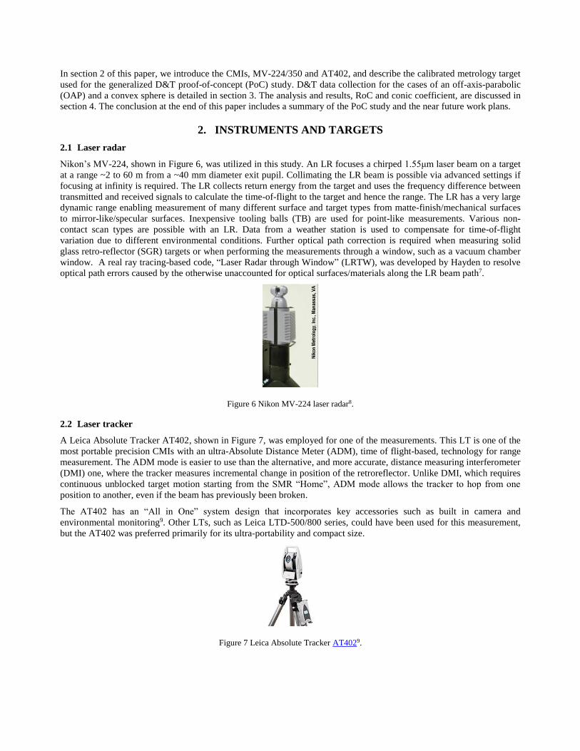
Nikon’s MV-224, shown in Figure 6, was utilized in this study. An LR focuses a chirped 1.55μm laser beam on a target
at a range ~2 to 60 m from a ~40 mm diameter exit pupil. Collimating the LR beam is possible via advanced settings if
focusing at infinity is required. The LR collects return energy from the target and uses the frequency difference between
transmitted and received signals to calculate the time-of-flight to the target and hence the range. The LR has a very large
dynamic range enabling measurement of many different surface and target types from matte-finish/mechanical surfaces
to mirror-like/specular surfaces. Inexpensive tooling balls (TB) are used for point-like measurements. Various non-
contact scan types are possible with an LR. Data from a weather station is used to compensate for time-of-flight
variation due to different environmental conditions. Further optical path correction is required when measuring solid
glass retro-reflector (SGR) targets or when performing the measurements through a window, such as a vacuum chamber
window. A real ray tracing-based code, “Laser Radar through Window” (LRTW), was developed by Hayden to resolve
optical path errors caused by the otherwise unaccounted for optical surfaces/materials along the LR beam path7.
Figure 6 Nikon MV-224 laser radar8.
2.2 Laser tracker
A Leica Absolute Tracker AT402, shown in Figure 7, was employed for one of the measurements. This LT is one of the
most portable precision CMIs with an ultra-Absolute Distance Meter (ADM), time of flight-based, technology for range
measurement. The ADM mode is easier to use than the alternative, and more accurate, distance measuring interferometer
(DMI) one, where the tracker measures incremental change in position of the retroreflector. Unlike DMI, which requires
continuous unblocked target motion starting from the SMR “Home”, ADM mode allows the tracker to hop from one
position to another, even if the beam has previously been broken.
The AT402 has an “All in One” system design that incorporates key accessories such as built in camera and
environmental monitoring9. Other LTs, such as Leica LTD-500/800 series, could have been used for this measurement,
but the AT402 was preferred primarily for its ultra-portability and compact size.
Figure 7 Leica Absolute Tracker AT4029.
2.3 Calibrated target
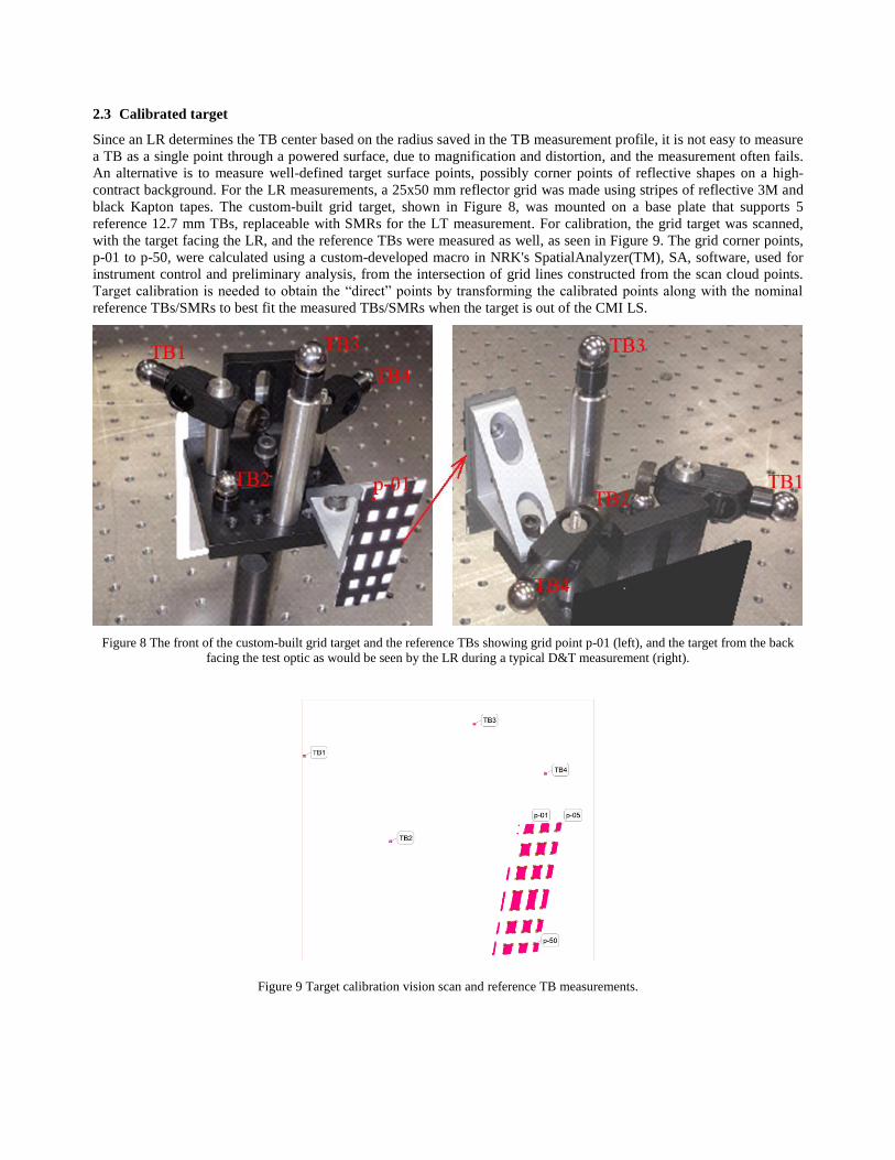
Since an LR determines the TB center based on the radius saved in the TB measurement profile, it is not easy to measure
a TB as a single point through a powered surface, due to magnification and distortion, and the measurement often fails.
An alternative is to measure well-defined target surface points, possibly corner points of reflective shapes on a high-
contract background. For the LR measurements, a 25x50 mm reflector grid was made using stripes of reflective 3M and
black Kapton tapes. The custom-built grid target, shown in Figure 8, was mounted on a base plate that supports 5
reference 12.7 mm TBs, replaceable with SMRs for the LT measurement. For calibration, the grid target was scanned,
with the target facing the LR, and the reference TBs were measured as well, as seen in Figure 9. The grid corner points,
p-01 to p-50, were calculated using a custom-developed macro in NRK's SpatialAnalyzer(TM), SA, software, used for
instrument control and preliminary analysis, from the intersection of grid lines constructed from the scan cloud points.
Target calibration is needed to obtain the “direct” points by transforming the calibrated points along with the nominal
reference TBs/SMRs to best fit the measured TBs/SMRs when the target is out of the CMI LS.
Figure 8 The front of the custom-built grid target and the reference TBs showing grid point p-01 (left), and the target from the back
facing the test optic as would be seen by the LR during a typical D&T measurement (right).
Figure 9 Target calibration vision scan and reference TB measurements.
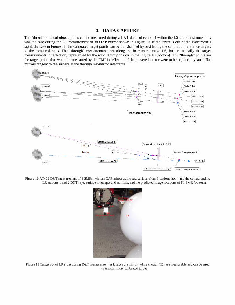
3. DATA CAPTURE
The “direct” or actual object points can be measured during a D&T data collection if within the LS of the instrument, as
was the case during the LT measurement of an OAP mirror shown in Figure 10. If the target is out of the instrument’s
sight, the case in Figure 11, the calibrated target points can be transformed by best fitting the calibration reference targets
to the measured ones. The “through” measurements are along the instrument-image LS, but are actually the target
measurements in reflection, represented by the solid “through” rays in the Figure 10 (bottom). The “through” points are
the target points that would be measured by the CMI in reflection if the powered mirror were to be replaced by small flat
mirrors tangent to the surface at the through ray-mirror intercepts.
Figure 10 AT402 D&T measurement of 3 SMRs, with an OAP mirror as the test surface, from 3 stations (top), and the corresponding
LR stations 1 and 2 D&T rays, surface intercepts and normals, and the predicted image locations of P1 SMR (bottom).
Figure 11 Target out of LR sight during D&T measurement as it faces the mirror, while enough TBs are measurable and can be used
to transform the calibrated target.
TB5
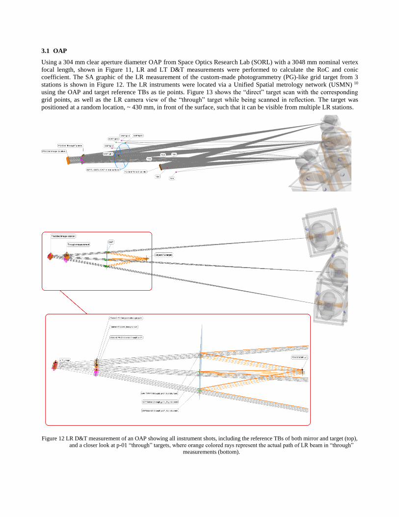
3.1 OAP
Using a 304 mm clear aperture diameter OAP from Space Optics Research Lab (SORL) with a 3048 mm nominal vertex
focal length, shown in Figure 11, LR and LT D&T measurements were performed to calculate the RoC and conic
coefficient. The SA graphic of the LR measurement of the custom-made photogrammetry (PG)-like grid target from 3
stations is shown in Figure 12. The LR instruments were located via a Unified Spatial metrology network (USMN) 10
using the OAP and target reference TBs as tie points. Figure 13 shows the “direct” target scan with the corresponding
grid points, as well as the LR camera view of the “through” target while being scanned in reflection. The target was
positioned at a random location, ~ 430 mm, in front of the surface, such that it can be visible from multiple LR stations.
Figure 12 LR D&T measurement of an OAP showing all instrument shots, including the reference TBs of both mirror and target (top),
and a closer look at p-01 “through” targets, where orange colored rays represent the actual path of LR beam in “through”
measurements (bottom).
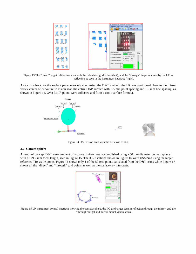
Figure 13 The “direct” target calibration scan with the calculated grid points (left), and the “through” target scanned by the LR in
reflection as seen in the instrument interface (right).
As a crosscheck for the surface parameters obtained using the D&T method, the LR was positioned close to the mirror
vertex center of curvature to vision scan the entire OAP surface with 0.5 mm point spacing and 1.5 mm line spacing, as
shown in Figure 14. Over 3x10⁵ points were collected and fit to a conic surface formula.
Figure 14 OAP vision scan with the LR close to CC.
3.2 Convex sphere
A proof of concept D&T measurement of a convex mirror was accomplished using a 50 mm diameter convex sphere
with a 129.2 mm focal length, seen in Figure 15. The 3 LR stations shown in Figure 16 were USMNed using the target
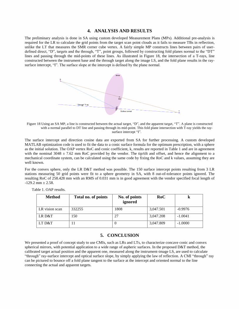
reference TBs as tie points. Figure 16 shows only 1 of the 50 grid points calculated from the D&T scans while Figure 17
shows all the “direct” and “through” grid points as well as the surface-ray intercepts.
Figure 15 LR instrument control interface showing the convex sphere, the PG grid target seen in reflection through the mirror, and the
"through" target and mirror mount vision scans.
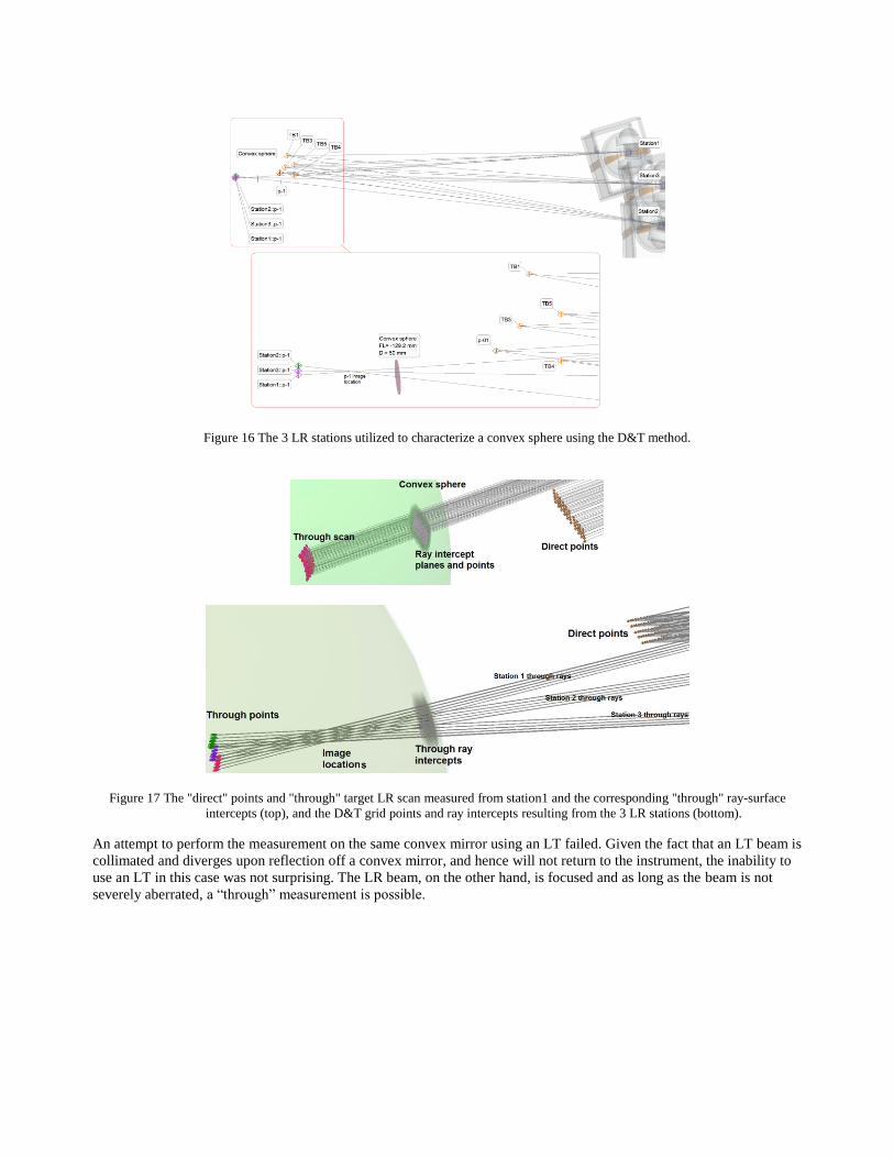
Figure 16 The 3 LR stations utilized to characterize a convex sphere using the D&T method.
Figure 17 The "direct" points and "through" target LR scan measured from station1 and the corresponding "through" ray-surface
intercepts (top), and the D&T grid points and ray intercepts resulting from the 3 LR stations (bottom).
An attempt to perform the measurement on the same convex mirror using an LT failed. Given the fact that an LT beam is
collimated and diverges upon reflection off a convex mirror, and hence will not return to the instrument, the inability to
use an LT in this case was not surprising. The LR beam, on the other hand, is focused and as long as the beam is not
severely aberrated, a “through” measurement is possible.
4. ANALYSIS AND RESULTS
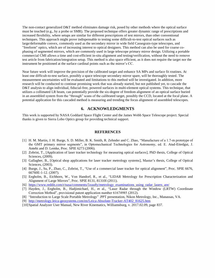
The preliminary analysis is done in SA using custom developed Measurement Plans (MPs). Additional pre-analysis is
required for the LR to calculate the grid points from the target scan point clouds as it fails to measure TBs in reflection,
unlike the LT that measures the SMR corner cube vertex. A fairly simple MP constructs lines between pairs of user-
defined direct, “D”, targets and the through, “T”, point groups, followed by constructing fold planes normal to the “DT”
lines and passing through the mid-points of these lines. As illustrated in Figure 18, the intersection of a T-rays, line
constructed between the instrument base and the through target along the image LS, and the fold plane results in the ray-
surface intercept, “I”. The surface slope at the intercept is defined by the plane normal.
Figure 18 Using an SA MP, a line is constructed between the actual target, “D”, and the apparent target, “T”. A plane is constructed
with a normal parallel to DT line and passing through its mid-point. This fold plane intersection with T-ray yields the ray-
surface intercept “I”.
The surface intercept and direction cosine data are exported from SA for further processing. A custom developed
MATLAB optimization code is used to fit the data to a conic surface formula for the optimum prescription, with a sphere
as the initial solution. The OAP vertex RoC and conic coefficient, k, results are reported in Table 1 and are in agreement
with the nominal 3048 ± 7.62 mm RoC provided by the vendor. The tip/tilt and offset, and hence the alignment to a
mechanical coordinate system, can be calculated using the same code by fixing the RoC and k values, assuming they are
well known.
For the convex sphere, only the LR D&T method was possible. The 150 surface intercept points resulting from 3 LR
stations measuring 50 grid points were fit to a sphere geometry in SA, with 8 out-of-tolerance points ignored. The
resulting RoC of 258.428 mm with an RMS of 0.031 mm is in good agreement with the vendor specified focal length of
-129.2 mm ± 2.58.
Table 1. OAP results.
Method Total no. of points No. of points
ignored
RoC k
LR vision scan 332255 1808 3,047.501 -0.9976
LR D&T 150 27 3,047.208 -1.0041
LT D&T 11 0 3,047.809 -1.0000
5. CONCLUSION
We presented a proof of concept study to use CMIs, such as LRs and LTs, to characterize concave conic and convex
spherical mirrors, with potential application to a wide range of aspheric surfaces. In the proposed D&T method, the
calibrated target actual position and the apparent one, measured along the instrument-image LS, are used to calculate
“through” ray-surface intercept and optical surface slope, by simply applying the law of reflection. A CMI “through” ray
can be pictured to bounce off a fold plane tangent to the surface at the intercept and oriented normal to the line
connecting the actual and apparent targets.
The non-contact generalized D&T method eliminates damage risk, posed by other methods where the optical surface
must be touched (e.g., by a probe or SMR). The proposed technique offers greater dynamic range of prescriptions and
increased flexibility, where setups are similar for different prescriptions of test mirrors, than other conventional
techniques. This approach might prove indispensable to testing some difficult-to-test optical surfaces such as
large/deformable convex, commonly used as the secondary mirror in wide field Cassegrain-type telescopes, and
"freeform" optics, which are of increasing interest to optical designers. This method can also be used for coarse co-
phasing of segmented mirrors, which are commonly used in large telescope primary mirror design. Utilizing a portable
commercial CMI allows a time and cost-efficient in-situ alignment and testing/verification, without the need to remove
test article from fabrication/integration setup. This method is also space efficient, as it does not require the target nor the
instrument be positioned at the surface cardinal points such as the mirror’s CC.
Near future work will improve the precision of the calibrated target and enhance SA MPs and surface fit routines. At
least one difficult-to-test surface, possibly a space telescope secondary mirror spare, will be thoroughly tested. The
measurement uncertainties will be evaluated and limitations to this method will be investigated. In addition, more
research will be conducted to continue promising work that was already started, but not published yet, to cascade the
D&T analysis to align individual, fiducial-free, powered surfaces in multi-element optical systems. This technique, that
utilizes a collimated LR beam, can potentially provide the six-degree of freedom alignment of an optical surface buried
in an assembled system from the “through” scans of the calibrated target, possibly the CCD, located at the focal plane. A
potential application for this cascaded method is measuring and trending the focus alignment of assembled telescopes.
6. ACKNOWLEDGMENTS
This work is supported by NASA Goddard Space Flight Center and the James Webb Space Telescope project. Special
thanks is given to Sierra Lobo Optics group for providing technical support.
REFERENCES
[1] H. M. Martin, J. H. Burge, S. D. Miller, B. K. Smith, R. Zehnder and C. Zhao, “Manufacture of a 1.7-m prototype of
the GMT primary mirror segments”, in Optomechanical Technologies for Astronomy, ed. E. Atad-Ettedgui, J.
Antebi and D. Lemke, Proc. SPIE 6273 (2006).
[2] Zobrist, T., [Application of laser tracker technology for measuring optical surfaces], PhD thesis, College of Optical
Sciences, (2009).
[3] Gallagher, B., [Optical shop applications for laser tracker metrology systems], Master’s thesis, College of Optical
Sciences, (2003).
[4] Burge, J., Su, P., Zhao, C., Zobrist, T., “Use of a commercial laser tracker for optical alignment”, Proc. SPIE 6676,
66760E-1-12. (2007).
[5] Eegholm, B., Eichhorn, W., Von Handorf, R., et al., “LIDAR Metrology for Prescription Characterization and
Alignment of Large Mirrors”, Proc. SPIE 8131, 81310I (2011).
[6] https://www.reddit.com/r/nasa/comments/5xuu8y/metrology_examinations_using_radar_lasers_are/
[7] Hayden, J., Eegholm, B., Hadjimichael, H., et al., “Laser Radar through the Window (LRTW) Coordinate
Correction Method”, provisional patent application number 61674985 (2012).
[8] “Introduction to Large Scale Portable Metrology” .PPT presentation, Nikon Metrology, Inc., Manassas, VA.
[9] http://metrology.leica-geosystems.com/en/Leica-Absolute-Tracker-AT402_81625.htm
[10] Spatial Analyzer User Manual, New River Kinematics, Williamsburg, v. 2017.02.09, page 837.