Optical Properties of the Atmosphere and Highway Lighting ...
10
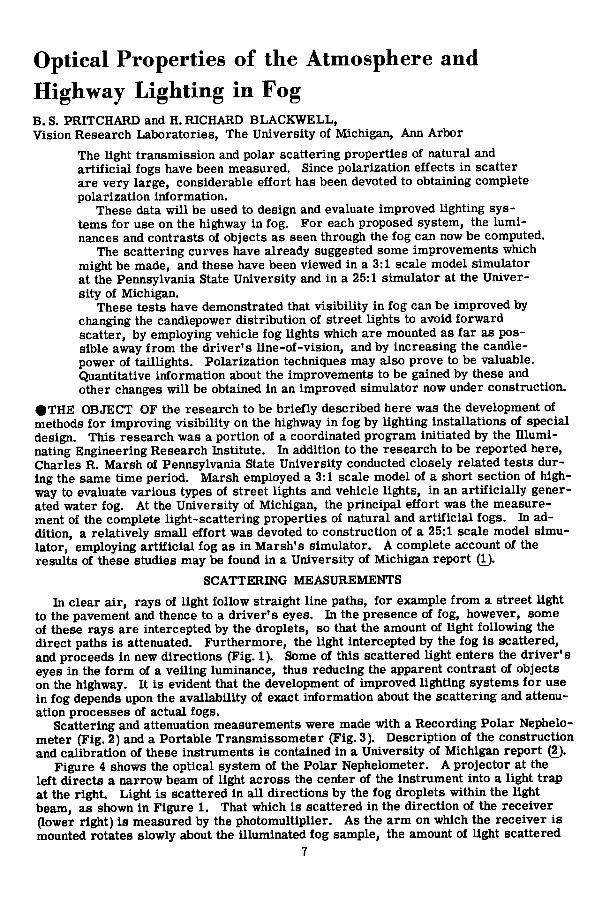
Optical Properties of the Atmosphere and Highway Lighting in Fog B. S. PRITCHARD and H. RICHARD BLACKWELL, Vision Research Laboratories, The University of Michigan, Ann Arbor The light transmission and polar scattering properties of natural and artificial fogs have been measured. Since polarization effects in scatter are very large, considerable effort has been devoted to obtaining complete polarization information. These data will be used to design and evaluate improved lighting sys- tems for use on the highway in fog. For each proposed system, the lumi- nances and contrasts of objects as seen through the fog can now be computed. The scattering curves have already suggested some improvements which might be made, and these have been viewed in a 3:1 scale model simulator at the Pennsylvania State University and in a 25:1 simulator at the Univer- sity of Michigan. These tests have demonstrated that visibility in fog can be improved by changing the candlepower distribution of street lights to avoid forward scatter, by employing vehicle fog lights which are mounted as far as pos- sible away from the driver's line-of-vision, and by increasing the candle- power of taillights. Polarization techniques may also prove to be valuable. Quantitative information about the improvements to be gained by these and other changes will be obtained in an improved simulator now under construction. •THE OBJECT OF the research to be briefly described here was the development of methods for improving visibility on the highway in fog by lighting installations of special design. This research was a portion of a coordinated program initiated by the Illumi- nating Engineering Research Institute. In addition to the research to be reported here, Charles R. Marsh of Pennsylvania State University conducted closely related tests dur- ing the same time period. Marsh employed a 3:1 scale model of a short section of high- way to evaluate various types of street lights and vehicle lights, in an artificially gener- ated water fog. At the University of Michigan, the principal effort was the measure- ment of the complete light-scattering properties of natural and artificial fogs. In ad- dition, a relatively small effort was devoted to construction of a 25:1 scale model simu- lator, employing artificial fog as in Marsh's simulator. A complete account of the results of these studies may be found in a University of Michigan report (1). SCATTERING MEASUREMENTS In clear air, rays of light follow straight line paths, for example from a street light to the pavement and thence to a driver's eyes. In the presence of fog, however, some of these rays are intercepted by the droplets, so that the amount of light following the direct paths is attenuated. Furthermore, the light intercepted by the fog is scattered, and proceeds in new directions (Fig. 1). Some of this scattered light enters the driver's eyes in the form of a veiling luminance, thus reducing the apparent contrast of objects on the highway. It is evident that the development of improved lighting systems for use in fog depends upon the availability of exact information about the scattering and attenu- ation processes of actual fogs. Scattering and attenuation measurements were made with a Recording Polar Nephelo- meter (Fig. 2) and a Portable Transmissometer (Fig. 3). Description of the construction and calibration of these instruments is contained in a University of Michigan report (2). Figure 4 shows the optical system of the Polar Nephelometer. A projector at the left directs a narrow beam of light across the center of the instrument into a light trap at the right. Light is scattered in all directions by the fog droplets within the light beam, as shown in Figure 1. That which is scattered in the direction of the receiver (lower right) is measured by the photomultiplier. As the arm on which the receiver is mounted rotates slowly about the illuminated fog sample, the amount of light scattered 7
Transcript of Optical Properties of the Atmosphere and Highway Lighting ...
Optical Properties of the Atmosphere and Highway Lighting in Fog B. S. PRITCHARD and H. RICHARD BLACKWELL, Vision Research Laboratories, The University of Michigan, Ann Arbor
The light transmission and polar scattering properties of natural and artificial fogs have been measured. Since polarization effects in scatter are very large, considerable effort has been devoted to obtaining complete polarization information.
These data wi l l be used to design and evaluate improved lighting systems for use on the highway in fog. For each proposed system, the luminances and contrasts of objects as seen through the fog can now be computed.
The scattering curves have already suggested some improvements which might be made, and these have been viewed in a 3:1 scale model simulator at the Pennsylvania State University and in a 25:1 simulator at the University of Michigan.
These tests have demonstrated that visibility in fog can be improved by changing the candlepower distribution of street lights to avoid forward scatter, by employing vehicle fog lights which are mounted as far as possible away from the driver's line-of-vision, and by increasing the candle-power of taillights. Polarization techniques may also prove to be valuable. Quantitative information about the improvements to be gained by these and other changes wil l be obtained in an improved simulator now under construction.
• T H E OBJECT OF the research to be briefly described here was the development of methods for improving visibility on the highway in fog by lighting installations of special design. This research was a portion of a coordinated program initiated by the Il luminating Engineering Research Institute. In addition to the research to be reported here, Charles R. Marsh of Pennsylvania State University conducted closely related tests during the same time period. Marsh employed a 3:1 scale model of a short section of highway to evaluate various types of street lights and vehicle lights, in an artificially generated water fog. At the University of Michigan, the principal effort was the measurement of the complete light-scattering properties of natural and artificial fogs. In addition, a relatively small effort was devoted to construction of a 25:1 scale model simulator, employing artificial fog as in Marsh's simulator. A complete account of the results of these studies may be found in a University of Michigan report (1).
SCATTERING MEASUREMENTS In clear air, rays of light follow straight line paths, for example from a street light
to the pavement and thence to a driver's eyes. In the presence of fog, however, some of these rays are intercepted by the droplets, so that the amount of light following the direct paths is attenuated. Furthermore, the light intercepted by the fog is scattered, and proceeds in new directions (Fig. 1). Some of this scattered light enters the driver's eyes in the form of a veiling luminance, thus reducing the apparent contrast of objects on the highway. It is evident that the development of improved lighting systems for use in fog depends upon the availability of exact information about the scattering and attenuation processes of actual fogs.
Scattering and attenuation measurements were made with a Recording Polar Nephelo-meter (Fig. 2) and a Portable Transmissometer (Fig. 3). Description of the construction and calibration of these instruments is contained in a University of Michigan report (2).
Figure 4 shows the optical system of the Polar Nephelometer. A projector at the left directs a narrow beam of light across the center of the instrument into a light trap at the right. Light is scattered in all directions by the fog droplets within the light beam, as shown in Figure 1. That which is scattered in the direction of the receiver (lower right) is measured by the photomultiplier. As the arm on which the receiver is mounted rotates slowly about the illuminated fog sample, the amount of light scattered
7

1 8 0 1 -
2 0 0 '
FOGBOW
SCATTER
80 10 INCIDENT LIGHT
FOG DROPLET
3 4 0 '
2 6 0 ' ? 7 0 «
2 8 0 *
Figure 1. The amount of light scattered by an average fog droplet i n various directions i s plotted on circular coordinates. Forward scatter i s so large i n comparison with right angle and back scatter that i t i s necessary to change the radial scale fac
tor in two steps of ten each.
at various angles with respect to the projector beam is recorded. The Transmissometer measures the amount by which the intensity of a narrow beam
of light is reduced after transmission through a long fog path. The projector (on the left in Fig. 3) and the photoelectric receiver (on the right) face each other with a separation of about one hundred feet. From the measured transmittance and the length of the path employed, i t is possible to compute the attenuation coefficient and the meteorological range, or the "visibility".
Figure 5 is a picture of the station wagon which has been equipped to transport the two instruments to the measurement site. With the gasoline-driven generator in the trailer to provide electrical power, atmospheric measurements can be made in any convenient location.
Figure 6 shows a set of polar scattering diagrams obtained in a natural fog in Ann Arbor on February 26, 1957. When the receiver of the instrument nearly faces the projector, the scattering angle, plotted on the abscissa, is small, and the photomulti-plier signal is very large, as shown at the upper left. The minimum scatter occurs at

TABLE 1 VOLUME SCATTERING INDICES OF FOG MEASURED ON FEB. 26, 1957
Scattering 3'UU Angle '. 3'UU cp (Degrees) . ( f t . " ^ ) ; ( f t . - ^ ) ; ( f t . - i ) ; ( f t . - l )
1.33 810 : 810 : 810 2 : 260 : 260 : 260 k 68 : 68 : 68 6 kO : ho : 1+0 8 : 36 36 : 36
10 25 25 : 25.2 15 17 17 16.9 20 9.6 10.6 .005 10.1 25 7.0 7.8 : .00!| 7.1+ 50 5.2 5-5 .003 5-3 35 k.O k.O .003 k.O ko 2.85 2.85 .002 2.85 i 5 1.95 2.17 .002 2.06 50 1.52 1.62 .001 l.J+7
.86 1.16 .001 1.01 60 •56 .75 .001 .65 65 .39 .1 9 .0009 .1+1+ 70 .295 .33 .0008 .31 75 .238 .227 .0007 .233 80 .192 .170 .0006 .181 85 .159 .117 .0006 .138 90 .156 .100 .0006 .118 95 .110 .076 .0005 .093
100 .103 .06lf .0005 .081+ 105 .101 .052
.060 .0005 .077
110 .097 .052 .060 .0005 .079
115 : .111 .067 .0006 : .088 120 : .Ihl .0006 : .108 125 : .191 : .08h .0009 : .138 130 : .158 : .0S5 : .0011 : .122 135 : .22 : .101 .0015 : .163 iko : .82 : .165 : .006 : .50
: .52 : .255 : .006 : .59 150 : .ha : . 55 : .0085 : .35 155 : .37 : -35 : .0095 .37 160 : .28 : .33 : .Olh : .3^
about 100 deg, and the fogbow (first cousin to the rainbow) shows as a large peak at about 140 deg.
The variety of curve shapes shown was obtained, all in the same fog, by inserting various types of polarizers in the instrument. The f i rs t symbol on each curve stands for the polarizer in the projector, and the second for that in the receiver. V, H, D, R, and U stand for vertical linear, horizontal linear, 45 deg diagonal linear, right circular, and unpolarized, respectively. The curve which would have been obtained if both the projected light and the receiver had been unpolarized is very nearly equal to the average of the VV and HH curves. Values are given in Table 1.
The volume scatterii^ index is defined by the following equation (3): _ I
p ' " E v in which I is the intensity (in flux per steradian) of the light scattered in a particular direction by a fog sample of volume v, and the illumination on the sample is E (flux

10 !
per unit area). In the Polar Nephelometer the volume of the scattering sample is defined by the intersection of the projector and receiver beams. The volume changes as the receiver swings around, but corrections are made for this effect during data analysis. (If these corrections were not made, the curves would rise even higher at both ends. )
The University of Michigan report (2) presents a much more complete description of these two instruments, along with a detailed analysis of the difficult calibration procedures.
The same report also presents the results of measurements of other natural fogs and of two artificially-produced fogs. They are not repeated here, as it is sufficient for present purposes to state that all water fogs measured to date produced generally the same shape curves when plotted on logarithmic scales. Curves for fogs of different densities differ from each other principally in the height of the curves on the paper. Only the data of February 26, 1957 are presented here, these being the most accurate and complete which have been obtained.
To date, only a green filter has been employed during fog measurements, as the effects of color in fog are known to be very small. On the other hand, much effort was devoted to obtaining complete information about polarization effects. These are very important in most scattering phenomena, yet they have never been measured before in either fog or clear air except at isolated scattering angles. It is evident that knowledge of the polarization properties of fog is needed when consideration is being given to the use of polarized vehicle lights and street lights, but it is not so obvious that it is important when no polarizers will be employed. However, there are many natural sources of partial polarization present everywhere. If ones eyes were sensitive to these effects as they are to color, would be observed that light reflected from most surfaces at large angles of incidence becomes strongly polarized, that portions of the blue sky are highly polarized, and that rainbows and fogbows are almost 100 percent polarized. Polarization effects cannot be ignored in any.optical system which includes more than one polarizing element, and the scattering data for unpolarized source and receiver must be used with discretion. I
Figure 2. The Recording Polar Nephelometer measures the polar scattering diagrams of natural atmospheres.
EVALUATION OF METHODS OF STUDY The following methods may be used in designing improved highway lighting systems
for fog: 1. Full scale tests of proposed designs in natural fogs. This method has the greatest

11
! Figure 3. The Portable Transmissometer measures fog densit ies . Under the projector (on the tripod at the l e f t ) i s the storage battery and current-control box for the 6 volt lairp in the projector. Under the photoelectric receiver (on the right) are the power supplies, a i tp l i f iers , and meters which indicate the current output of the photo-
mult ipl ier .
validity when used properly, but it suffers from the disadvantage that fogs rarely occur when they are wanted, and even when they do occur the fog density cannot be controlled.
2. Scale model simulator tests with artificial fog. Good control of conditions can be obtained easily and rapidly. It has been shown that the visibility aspects of the fog driving problem can be very closely simulated.
3. Computation. From the scattering data presented above it is possible to compute the luminances and contrasts of objects on the highway in fogs of various densities, for any proposed or existing lighting arrangement. Available visual data (4) can then be used to predict the visibility of any given object. One advantage of this method is that a more thorough understanding is obtained of the reasons why one design is better or worse than another, and the increased understanding naturally leads to improved designs. For single scattering, the method is fast and simple, but when light which is

12
D E P O L A R I Z E R
L I G H T T R A P
C A L I B R A T I O N S C R E E N
P R O J E C T O R B E A M L I G H T T R A P
S A M P L E
S P A C E
P O L A R I Z E R
F I L T E R S
P H O T O M U L T I P L I E R
Figure k. The o p t i c a l system of the Recording Polar Nephelometer. The p r o j e c t o r a t the l e f t I l l u m i n a t e s the fog w i t h i n the p r o j e c t o r heam. The r e c e i v e r , a t the lower
r i g h t , r e c e i v e s the l i g h t s c a t t e r e d from a p o r t i o n of the beam a t a v a r i a b l e angle.
Figure 5. The a m p l i f i e r c o n t r o l s and recorder f o r the Recording P o l a r Nephelometer, which i s shown on the ground, are rack-mounted behind the f r o n t seat of the v e h i c l e . When the two u n i t s of the Portable Transmissometer are used a t long separation d i s t a n c e s , r a d i o s (the antennae of which are v i s i b l e i n the p i c t u r e ) are used f o r com
munication.

13
scattered more than once by the fog contributes appreciably to the observed l u m i nance, the computations become lengthy.
Each of these methods i s valuable, and an effective attack on the problem employs a l l three. The simulator method is valuable both i n the early stages when radically different designs are being i n vestigated and later when quantitative comparisons of proposed designs are necessary. The computational method w i l l be par t icula r ly valuable in optimizing the f ina l design because the effects of making small changes can be assessed accurately. Road tests should also be made whenever possible to make certain that no important aspects of the driving situation are omitted. The potentials and limitations of each of these methods have been investigated but none has been fu l ly exploited as yet.
SIMULATOR STUDIES
A relatively simple simulator was constructed at a scale of 25:1, with which qualitative visual comparisons were made of various lighting systems (Figs. 7, 8, and 9). The following general conclusions were reached:
1. A street l ight f o r use i n fog should have a relatively narrow beam spread, with the beam approximately perpendicular to the dr iver ' s l ine-of-sight. The units could be eithei' overhead or at a lower elevation on the side of the road. This concept was suggested by the large dip i n the polar scattering diagrams at about 100 deg, and simulator tests confirmed that the veiling luminance was appreciably r e duced by this change i n street light design. Many more lamps would be needed to achieve the present road coverage, but the total power consumed would probably not be increased If the units were efficiently designed.
2. Vehicle lights f o r use i n fog should be mounted as f a r as possible away f r o m the d r iver ' s Une-of-sight, and there should be a sharp cutoff i n the candlepower d is t r ibution curve to avoid il luminating the fog Immediately in f ron t of the vehicle.
3. Veil ing luminance can be reduced and the contrasts of most objects increased by the use of a polarized fog light (only one can be used effectively) and an orthogonal viewing polarizer. I t i s not yet certain, however, that the gains are enough to outweigh the attendant disadvantages.
4. Vehicle tallligfats should have increased candlepower f o r use i n fog, i n accordance with the fact that self-luminous objects of high Intensity are usually visible at much greater distances than reflecting objects.
5. Use of polarized street lights with orthogonal viewers should be Investigated f u r ther, although In i t ia l tests have been unfavorable. The veiling luminance caused by the fog i s reduced; but the luminances of most other objects are also reduced, not only by the normal polarizer losses but also by the fact that most objects do not depolarize the
SCATTERING ANGLE * (DEGREES)
Figure 6. Polar Scattering Diagrams on rectangular coordinates vLth logarltbmlc
ordinate scale.

14 I
F i g u r e 7. The covers of the "fog box" have been r a i s e d to attempt to show the 25:1 s c a l e model c a r s immersed i n a r t i f i c i a l fog. The "peep hole" through which one obtains
a d r i v e r ' s - e y e view of the roadway i s i n the near end of the box.

15
Figure 8. Improved highway l i g h t i n g I n fog. T h i s photograph was t a i e n through the peep hole I n the fog box, w i t h the t a i l l i g h t s of i n c r e a s e d caadlepower on the receding c a r a t the r i g h t , narrow heam s t r e e t l i g h t s and "cross-eyed" low-mounted fog l i g h t s on
the approaching c a r and the d r i v e r ' s c a r .
F i g u r e 9. Normal highway l i g h t i n g f o r comparison w i t h the previous f i g u r e . (Glare from the overhead l i g h t s i s exaggerated by the photographic reproduction process.)

16
light that they reflect, especially when the surfaces are wet and the angles of incidence are large. Possibly some combination of polarized and unpolarized lights w i l l prove effective in future tests.
FUTURE PLANS
Work has started on a t r i a l installation on the New Jersey Turnpike to evaluate some of the suggestions which have been made to date. At the same time, i t i s planned to construct at the University of Michigan an improved simulator at a scale of 10:1. Can-dlepower distributions w i l l be more carefully controlled than previously, and quantitative measurements w i l l be made of the improvements achieved by the various proposed changes.
SUMMARY
"The solution" to the problem of v is ib i l i ty on the highway in fog has certainly not been obtained, but the ground work has been carefully laid f o r future studies which w i l l lead to improved lighting systems. Basic information about the light-scattering properties of fog has been obtained, the capabilities of various methods of approach to the problem have been evaluated, and methods of simulation have been developed. Simulator tests at the Pennsylvania State University and the University of Michigan have confirmed the fact that contrasts of objects on the roadway can be improved i f a new concept of street light design, suggested by the scattering data, is adopted.
ACKNOWLEDGMENT
This work was supported by Grant #47-B f r o m the Illuminating Engineering Research Institute, N . Y .
REFERENCES
1. Pri tchard, B. S., and Blackwell, H. R., "Prel iminary Studies of Vis ib i l i ty on the Highway in Fog . " Engng. Res. Inst. Rpt. No. 2557-2-F, Univ. of M i c h . , (July 1957).
2. Pri tchard, B. S., and Ell iot t , W. G. , "Two Instruments f o r Measurement of the Optical Properties of the Atmosphere. " Engng. Res. Inst. Rpt. No. 2144-250-T, Univ. of M i c h . , (1958).
3. Middleton, W. E. K . , "Vision Through the Atmosphere," Univ. of Toronto Press, (1952).
4. Blackwell , H. R. , "Brightness Discrimination Data f o r the Specifications of Quant i ty of I l luminat ion." I l ium. Engr. , N . Y . , 47, 602, (1952).