Optical Neural Interfaces - Stanford University
27
Optical Neural Interfaces Melissa R. Warden, 1, 2 Jessica A. Cardin, 5, 6 and Karl Deisseroth 2, 3, 4 1 Department of Neurobiology and Behavior, Cornell University, Ithaca, New York 14853; email: [email protected] Departments of 2 Bioengineering and 3 Psychiatry and Behavioral Sciences, 4 Howard Hughes Medical Institute, Stanford University, Stanford, California 94305; email: [email protected] 5 Department of Neurobiology, 6 Kavli Institute for Neuroscience, Yale University, New Haven, Connecticut 06520 Annu. Rev. Biomed. Eng. 2014. 16:103–29 The Annual Review of Biomedical Engineering is online at bioeng.annualreviews.org This article’s doi: 10.1146/annurev-bioeng-071813-104733 Copyright c 2014 by Annual Reviews. All rights reserved Keywords optogenetics, neurophysiology, imaging, channelrhodopsin, halorhodopsin, GCaMP Abstract Genetically encoded optical actuators and indicators have changed the land- scape of neuroscience, enabling targetable control and readout of specific components of intact neural circuits in behaving animals. Here, we review the development of optical neural interfaces, focusing on hardware designed for optical control of neural activity, integrated optical control and electrical readout, and optical readout of population and single-cell neural activity in freely moving mammals. 103 Annu. Rev. Biomed. Eng. 2014.16:103-129. Downloaded from www.annualreviews.org by Stanford University - Main Campus - Lane Medical Library on 07/11/14. For personal use only.
Transcript of Optical Neural Interfaces - Stanford University

BE16CH05-Warden ARI 28 May 2014 11:44
Optical Neural InterfacesMelissa R. Warden,1,2 Jessica A. Cardin,5,6
and Karl Deisseroth2,3,4
1Department of Neurobiology and Behavior, Cornell University, Ithaca, New York 14853;email: [email protected]
Departments of 2Bioengineering and 3Psychiatry and Behavioral Sciences, 4Howard HughesMedical Institute, Stanford University, Stanford, California 94305; email: [email protected] of Neurobiology, 6Kavli Institute for Neuroscience, Yale University,New Haven, Connecticut 06520
Annu. Rev. Biomed. Eng. 2014. 16:103–29
The Annual Review of Biomedical Engineering isonline at bioeng.annualreviews.org
This article’s doi:10.1146/annurev-bioeng-071813-104733
Copyright c© 2014 by Annual Reviews.All rights reserved
Keywords
optogenetics, neurophysiology, imaging, channelrhodopsin,halorhodopsin, GCaMP
Abstract
Genetically encoded optical actuators and indicators have changed the land-scape of neuroscience, enabling targetable control and readout of specificcomponents of intact neural circuits in behaving animals. Here, we reviewthe development of optical neural interfaces, focusing on hardware designedfor optical control of neural activity, integrated optical control and electricalreadout, and optical readout of population and single-cell neural activity infreely moving mammals.
103
Ann
u. R
ev. B
iom
ed. E
ng. 2
014.
16:1
03-1
29. D
ownl
oade
d fr
om w
ww
.ann
ualr
evie
ws.
org
by S
tanf
ord
Uni
vers
ity -
Mai
n C
ampu
s -
Lan
e M
edic
al L
ibra
ry o
n 07
/11/
14. F
or p
erso
nal u
se o
nly.

BE16CH05-Warden ARI 28 May 2014 11:44
Contents
1. INTRODUCTION . . . . . . . . . . . . . . . . . . . . . . . . . . . . . . . . . . . . . . . . . . . . . . . . . . . . . . . . . . . . 1042. OPTICAL CONTROL OF NEURAL ACTIVITY . . . . . . . . . . . . . . . . . . . . . . . . . . . . . . 105
2.1. Genetically Encoded Optical Actuators . . . . . . . . . . . . . . . . . . . . . . . . . . . . . . . . . . . . . . 1052.2. Single-Site Intracranial Light Delivery . . . . . . . . . . . . . . . . . . . . . . . . . . . . . . . . . . . . . . 1062.3. Light Sources . . . . . . . . . . . . . . . . . . . . . . . . . . . . . . . . . . . . . . . . . . . . . . . . . . . . . . . . . . . . . . 1082.4. Multisite Optical-Neural Interfaces . . . . . . . . . . . . . . . . . . . . . . . . . . . . . . . . . . . . . . . . . . 1092.5. Wireless Optogenetic Control . . . . . . . . . . . . . . . . . . . . . . . . . . . . . . . . . . . . . . . . . . . . . . 110
3. INTEGRATED OPTICAL CONTROL AND ELECTRICALREADOUT . . . . . . . . . . . . . . . . . . . . . . . . . . . . . . . . . . . . . . . . . . . . . . . . . . . . . . . . . . . . . . . . . . . . 1113.1. Silicon Probes with Integrated Light Guides . . . . . . . . . . . . . . . . . . . . . . . . . . . . . . . . . 1123.2. Stereotrode and Tetrode Microdrives . . . . . . . . . . . . . . . . . . . . . . . . . . . . . . . . . . . . . . . 1133.3. Fixed-Wire Arrays . . . . . . . . . . . . . . . . . . . . . . . . . . . . . . . . . . . . . . . . . . . . . . . . . . . . . . . . . . 1143.4. Multielectrode Arrays . . . . . . . . . . . . . . . . . . . . . . . . . . . . . . . . . . . . . . . . . . . . . . . . . . . . . . . 114
4. OPTICAL READOUT OF NEURAL ACTIVITY . . . . . . . . . . . . . . . . . . . . . . . . . . . . . . 1154.1. Genetically Encoded Activity Indicators . . . . . . . . . . . . . . . . . . . . . . . . . . . . . . . . . . . . . 1154.2. Population Monitoring with Single Fibers and Fiber Bundles . . . . . . . . . . . . . . . . . 1164.3. Cellular Imaging with Head-Mounted Two-Photon Microscopy . . . . . . . . . . . . . . 1184.4. Cellular Imaging with Head-Mounted One-Photon Microscopy . . . . . . . . . . . . . . 120
5. FUTURE DIRECTIONS . . . . . . . . . . . . . . . . . . . . . . . . . . . . . . . . . . . . . . . . . . . . . . . . . . . . . . 121
1. INTRODUCTION
The mammalian brain, which is more complex than any electronic circuit yet devised, com-prises billions of components with innumerable distinct shapes, sizes, activity patterns, wiringpatterns, and molecular phenotypes. Progress toward untangling this complexity had for manyyears followed two parallel paths, one focusing on function of these circuit elements (electro-physiology) and the other on neurochemical and structural identity (anatomy). Electrophys-iological methods can be used to record the activity of neurons in behaving animals, butwith limited means to link these neural activity patterns identified in behavior to anatomi-cal identity of the very same neurons. Moreover, the brain can be electrically stimulated toevoke specific memories, behaviors, or affective states (1–3), but the mechanisms by whichthese manipulations act through specific neural circuit elements and wiring can be difficult todetermine.
Recent convergence of the molecular and systems branches of neuroscience, however, has ledto unprecedented progress toward a systematic linkage between neuronal structure and func-tion, driven in part by the development of genetically encodable neural actuators and indicators(4–7). With these biological tools, neuroscientists can now control and image the activity ofgenetically or anatomically defined specific cell types in the brains of behaving mammals andcan finally begin to connect this behaviorally relevant function to detailed structure. However,engineering of novel devices is also required, as understanding how circuit elements producecomplex behaviors in mammalian systems requires specialized neural interfaces to enable ap-plication of optical tools in freely behaving animals. We review this rapidly developing fieldhere.
104 Warden · Cardin · Deisseroth
Ann
u. R
ev. B
iom
ed. E
ng. 2
014.
16:1
03-1
29. D
ownl
oade
d fr
om w
ww
.ann
ualr
evie
ws.
org
by S
tanf
ord
Uni
vers
ity -
Mai
n C
ampu
s -
Lan
e M
edic
al L
ibra
ry o
n 07
/11/
14. F
or p
erso
nal u
se o
nly.

BE16CH05-Warden ARI 28 May 2014 11:44
2. OPTICAL CONTROL OF NEURAL ACTIVITY
2.1. Genetically Encoded Optical Actuators
Recent years have seen the development of a comprehensive toolbox of genetically encoded op-tical actuators from microbial organisms (8–21). These proteins, which are derived from single-component opsin genes, permit fine control over the activity of genetically or topologically definedneural circuit elements embedded in a matrix of dissimilar cell types. Although electrical stimu-lation has been used with great efficacy to both control and probe the function of discrete brainregions and to provide therapeutic benefit, it is not capable of targeting genetically specified celltypes (Figure 1a), a disadvantage that can be overcome with genetically encoded actuators.
Na+
Na+ Na+
Na+
Na+
Na+
K+
H+
H+
H+H+
H+
H+
K+
K+
K+
K+
K+
Na+Na+
Na+Na+ Ca2+
Ca2+Ca2+
Na+
Na+
ChR
Cl–
Cl–
Cl–
Cl–Cl–
Cl–
Cl–
Cl–
Cl–
Cl–
HR
[IP3]
[DAG]
[cAMP][cAMP]
Gs
OptoXR
Depth electrode(1.27-mm diameter)
Targetedneuron type
Adjacentnontargeted
neuron
Targeted neuron type expressing
ChR2 or NpHR
Adjacent nontargetedneuron
Implanted optical fiber(0.2-mm diameter)
ChR2 or NpHR
Electrical stimulation Optical stimulationa
b
GiGq GsGsGsGsGsGGGqqGGGqq GGiGGiiCl–
Cl–
Cl–
Cl–
Cl–
Cl–
Figure 1Optogenetics for control of genetically or topologically defined neural subtypes. (a) Electrical stimulationcan be effective for modulating local neural activity, but the heterogeneity of brain tissue precludes controlof single cell types using this method (left). Genetically targetable optogenetic constructs enable moreprecise stimulation of specified neural subtypes intermingled with nontargeted neurons (right). (Panelmodified with permission from 154.) (b) Many different types of optogenetic constructs have been developedfor control of neural activity. Currently available tools allow for induction of action potentials (ChR-familylight-gated cation channels shown, left), silencing of neural activity (HR-family light-gated chloride pumpsshown, middle; proton pumps may also be used), and modulation of intracellular signaling cascades [OptoXRfamily (153) shown, right; other classes of biochemical tool may also be used], among many otherapplications. (Panel modified with permission from 4.) Abbreviations: ChR, channelrhodopsin; ChR2,channelrhodopsin-2; HR, halorhodopsin; NpHR, halorhodopsin from Natronomonas pharaonis; optoXR,opsin-receptor chimaera.
www.annualreviews.org • Optical Neural Interfaces 105
Ann
u. R
ev. B
iom
ed. E
ng. 2
014.
16:1
03-1
29. D
ownl
oade
d fr
om w
ww
.ann
ualr
evie
ws.
org
by S
tanf
ord
Uni
vers
ity -
Mai
n C
ampu
s -
Lan
e M
edic
al L
ibra
ry o
n 07
/11/
14. F
or p
erso
nal u
se o
nly.

BE16CH05-Warden ARI 28 May 2014 11:44
Optical neural control has been a long-sought goal (22–24), but the microbial single-componenttools (8–21) have turned out to be critical for genetically encoded optical actuation, including inmammalian systems, owing to several factors including speed, reliability, and targetability. The firstmicrobial opsin successfully employed to excite neural activity and alter behavior in freely movingmammals (8) was channelrhodopsin-2 (ChR2), a member of the channelrhodopsin (ChR) family(10) (Figure 1b, left). These membrane-bound nonselective cation channels could be activatedwith pulses of blue light to depolarize expressing neurons and induce single action potentials (8).This was quickly followed by the development of the inhibitory halorhodopsin from Natronomonaspharaonis (NpHR) (9, 11, 14) (Figure 1b, middle), a chloride pump that could hyperpolarize andtherefore silence expressing neurons upon the application of yellow light. Further engineeringand genomic exploration produced spectrally shifted opsins (12, 20, 25), opsins for biochemicalcontrol (153) (Figure 1b, right), opsins for proton pumping–based inhibition (14, 15, 21), fasteropsins (16, 18), highly expressing opsins (16, 17, 19–21), and bistable step-function opsins (SFOs)(13, 20), creating a wide spectrum of tools for optical neural control (21).
2.2. Single-Site Intracranial Light Delivery
Prior to the development of specialized devices for intracranial light delivery in freely behavingmammals, optogenetic stimulation had been successfully employed to drive neural activity inboth cultured neuronal and acute slice preparations (8, 9), as well as to drive simple behaviors ininvertebrates (9, 26). In these preparations, light of the appropriate wavelength and power couldbe delivered from an arc lamp through the imaging objective for full-field optogenetic stimulation,but this approach was not well suited to stimulation deep within the brain, or for flexible behavioralcontrol in freely moving mammals.
The first demonstration of optical control of behavior in freely moving rodents, in 2007 (27),employed an intracranial optical fiber directly coupled to a laser-diode light source; this original op-tical neural interface device had been developed and described in an optogenetic application to in-tact anesthetized rodents earlier that same year (27a) (Figure 2a). In this first approach, a metallic/plastic cannula originally designed for intracranial drug delivery (Plastics One) was surgically im-planted above the brain region of interest. Immediately following implantation, a viral vector foropsin delivery was injected through the implanted cannula. This design ensured coregistration ofthe virally transduced neuronal population with the light source. During subsequent behavioraltesting, a flexible multimode optical fiber coupled to the laser-diode light source was inserteddirectly into the cannula (flush with the cannula tip). Using this approach it was possible to inducewhisker twitches upon illumination of ChR2-expressing neurons in motor cortex of living rats andmice (27a); this report was followed within a few months by a separate study showing optogeneticcontrol of behavioral state transitions (sleep/wake) in freely moving mice (27).
Key advantages of this system include the ability to stimulate either surface brain tissue orsubcortical structures, as the cannula can be placed stereotaxically to target any brain region ofinterest. In addition, simultaneous optogenetic and pharmacological manipulation can be per-formed through the same cannula, a useful property because pharmacological interventions addan informative mechanistic component to many optogenetic studies. Subsequent work refinedthis approach to permit secure, long-term fiber placement, as well as free rotation of the animalusing a commutator (fiberoptic rotary joint; Doric Lenses), which is crucial for many behavioralexperiments in freely moving rodents (5, 20, 27, 28).
A subsequently developed system for optogenetic stimulation in freely behaving rodents usedchronic implantation of a short optical fiber stub coupled to a metal ferrule (Figure 2b) (29).During behavioral testing, the metal ferrule could be coupled to an external fiber with a ceramic
106 Warden · Cardin · Deisseroth
Ann
u. R
ev. B
iom
ed. E
ng. 2
014.
16:1
03-1
29. D
ownl
oade
d fr
om w
ww
.ann
ualr
evie
ws.
org
by S
tanf
ord
Uni
vers
ity -
Mai
n C
ampu
s -
Lan
e M
edic
al L
ibra
ry o
n 07
/11/
14. F
or p
erso
nal u
se o
nly.

BE16CH05-Warden ARI 28 May 2014 11:44
Cranioplasticcement
Cannula
Opticalfiber
Skull
Cortex
Illumination
Layer 1
Layer 2
Layer 3
Layer 4
Releasablebase200 μm
MicroelectrodeMicroelectrode
μ-IPDμ-IPD
μ-ILEDsμ-ILEDs
Temperaturesensor
Temperaturesensor
Injectionmicroneedle
Injectionmicroneedle
a bb
c d
e
Figure 2Optical-neural interfaces for light delivery to brain tissue in freely moving mammals. (a) The originalfiberoptic neural interface (27a), in this case implemented via a cannula implanted over the brain region ofinterest; the optical fiber coupled to a light source is inserted during behavioral testing. This approach allowsfor simple integration with pharmacological methods. (Panel modified with permission from 27a.) (b) Lightdelivery through an implanted fiber. An optical fiber stub is implanted over the brain region of interest and iscoupled to a fiberoptic tether with a ceramic sheath during behavior. This approach is well suited tohigh-throughput behavioral testing but cannot be easily combined with pharmacology at the same site. Bothcannulas and optical fiber stubs can be used for single- or dual-site illumination. (Panel modified withpermission from 29 and 154.) Further advancements include (c) multisite light delivery (panel modified withpermission from 42) and (d ) wireless control (panel modified with permission from 37), both appropriatelysized for use in freely behaving mice. (e) Injectable optoelectronics for wireless multisite multiwavelengthoptical stimulation/sensing, electrophysiology, and temperature sensing with coregistration and minimaltissue damage. Multiple μ-ILED light sources (a thousandth the size of conventional LEDs) can beindependently controlled and can deliver a choice of wavelengths. Abbreviations: μ-IPD, microscaleinorganic photodetector; μ-ILED, microscale inorganic light-emitting diode. (Panel modified withpermission from 48.)
sheath and commutated for free rotation during behavior as above. Significant advantagesof this system over the previously described cannula-based system include (a) avoidance ofrepeated insertion of an external fiber into the brain, thereby reducing damage to neural tissue;(b) reduced likelihood of breaking the external fiber upon insertion; and (c) reduced handlingstress for the rodent. However, the ability to simultaneously perform same-site intracranial
www.annualreviews.org • Optical Neural Interfaces 107
Ann
u. R
ev. B
iom
ed. E
ng. 2
014.
16:1
03-1
29. D
ownl
oade
d fr
om w
ww
.ann
ualr
evie
ws.
org
by S
tanf
ord
Uni
vers
ity -
Mai
n C
ampu
s -
Lan
e M
edic
al L
ibra
ry o
n 07
/11/
14. F
or p
erso
nal u
se o
nly.

BE16CH05-Warden ARI 28 May 2014 11:44
pharmacology is lost. Additionally, viral injections must be performed separately, leading to apossible misregistration of opsin expression and fiber targeting. In practice, this technique is usedprimarily for high-throughput behavioral screening, whereas the cannula approach is used whenintegrated optogenetic and pharmacological experiments are performed. Commercially availableimplantable fibers with ferrules may currently be obtained from several vendors, includingDoric Lenses, Thorlabs, and Plexon Inc. Additionally, construction of these devices may beaccomplished easily in the laboratory at very low cost (30).
2.3. Light Sources
Light delivery to brain tissue through an intracranial fiber has been accomplished primarily usingeither laser (diode or diode-pumped solid state, DPSS) or light-emitting diode (LED) light sources.Each has advantages, and the appropriate system for any given experiment will ultimately be drivenby the relative importance of variables such as cost, size, light power, spectral tuning, stability,and temporal properties.
Fiber-coupled lasers have been the light source of choice for many recent experiments (20, 27,27a, 31–36), in large part because the efficient coupling between light source and fiber enables de-livery of high-powered illumination directly to neural tissue. Although control of neuronal firingupon photostimulation requires relatively low irradiance values at the microbial opsin-expressingcell (1–5 mW/mm2) (8, 9), the high degree of light scattering and absorption by neural tissue (5)creates a practical in vivo requirement for orders-of-magnitude-greater light levels at the fiber tip,depending on light sensitivity of the cells expressing the opsin of choice (13, 21). Lasers with thecapacity to deliver up to 100-mW (or more) light power are typically used in the laboratory and arecommercially available from several sources (OEM Laser Systems, CrystaLaser, Cobolt, Laser-Glow, Thorlabs, Omicron, and OptoEngine). A light source of this power enables delivery of lightinto the brain at the appropriate intensity to induce optogenetic neural activation, even after lossesintroduced through fiber coupling, fiberoptic rotary joints for commutation, or splitting for bilat-eral illumination. Additional advantages of laser light sources include very low beam divergenceand tight spectral bandwidth—important for multicolor, multiopsin experimental configurations(discussed below).
Despite these advantages, laser systems have several drawbacks. Although some wavelengthsare relatively inexpensive (∼$1,000 for a 473-nm laser), yellow light sources in particular can bemore costly ($5,000–10,000 for a 590-nm laser). Additionally, lasers can be fragile (particularlyfor yellow wavelengths), require long warm-up times, and are not guaranteed to provide stableillumination power without considerable expense. Laser light sources are also bulky and canrequire specialized optical components to couple light to the fiber. Although analog modulationcan be used with lasers to vary power output, the precision of this manipulation is somewhatlacking. Moreover, although short, millisecond-width pulses can be generated with lasers of somewavelengths, large transients are often seen with pulse shape significantly deviating from a squarewaveform; indeed currently, yellow lasers cannot be practically modulated on this timescale andare instead routinely used with a shutter for temporal control of illumination, but shutters can, inturn, introduce additional problems. Though effective for the timescale on which this wavelengthis typically used for inhibition (seconds to minutes), the mechanical action of shutters produces asound that may be confounding for behavioral experiments; liquid crystal shutters are significantlyquieter but are generally incompatible with the power levels required for in vivo experiments.Finally, laser light sources also require the use of a fiberoptic rotary joint when used with freelybehaving mammals, which imposes additional limitations; these joints are expensive, introduce
108 Warden · Cardin · Deisseroth
Ann
u. R
ev. B
iom
ed. E
ng. 2
014.
16:1
03-1
29. D
ownl
oade
d fr
om w
ww
.ann
ualr
evie
ws.
org
by S
tanf
ord
Uni
vers
ity -
Mai
n C
ampu
s -
Lan
e M
edic
al L
ibra
ry o
n 07
/11/
14. F
or p
erso
nal u
se o
nly.

BE16CH05-Warden ARI 28 May 2014 11:44
variation in light power as the joint is rotated, and must be integrated with electrical commutationsystems typically used in neurophysiological experiments.
LED light sources have become increasingly suitable for optogenetic experimentation in freelymoving mammals (28, 37, 38) and have been used for motor and behavioral control in several papers(28, 37, 39–41). LED configuration can be quite flexible and modified to align with experimentalrequirements; these light sources may be used above a thinned skull for a noninvasive experimentalmanipulation, mounted directly above the cortical surface, inserted into the brain, or remotelycoupled to a fiber to target deep brain structures. Less expensive (∼$300), smaller, more stable,more reliable, and available in a range of wavelengths, LED light sources have only one seriousdrawback for single-color experiments: relatively poor light source–fiber coupling and the con-comitant difficulty in obtaining light powers high enough to drive behavioral responses upon invivo stimulation. Efficient coupling to an insertable light guide is important because direct inser-tion of an LED itself into target tissue typically generates local heating. An additional drawbackfor multicolor experiments is the relatively broad spectral tuning of LEDs, on the order of 10 to50 nm at half-max, which may negatively influence both dual-opsin stimulation experiments andsimultaneous optical stimulation/readout with fluorescent Ca2+ or voltage indicators.
Recent improvements in the efficiency of fiber–LED coupling have enabled significantlyhigher light powers, particularly for blue wavelengths. LEDs from Plexon Inc. are currentlyavailable in nine wavelengths ranging from royal blue to infrared (450–940 nm) and, thus, suitablefor many optogenetics experiments. The blue (465-nm) LEDs, in particular, are quite powerful,delivering ∼25 mW from the fiber tip if used with a 200-μm fiber. However, some LEDscontinue to deliver relatively low powers; for example, yellow LEDs currently deliver little morethan 3 mW from the fiber tip. This level of power output may be useful for some experiments,but higher light powers are more commonly desired, particularly if the light must run throughmultiple coupling stages or be split for bilateral illumination. Available adjacent wavelengths,such as orange (620 nm) or green (525 nm), are accessible with higher-powered LEDs that maypotentially be used instead to activate the same opsins. As inexpensive, higher-powered LEDsbecome commercially available (as from Luxeon), novel configurations of fiber-coupled LEDarrays may be assembled for optogenetics applications.
Other advantages of LED-based systems include ease of commutation of the electrical powercable, compared with a diode-coupled optical fiber. Simultaneous commutation with neurophysio-logical recording equipment is relatively straightforward, as an extra electrical channel can be usedfor this purpose and need not require a new design. Optical fiber commutation with laser-based sys-tems requires concentric commutation of optical fiber and electrical wires, which may not be easyto integrate with some currently available systems. In addition, when electrical commutation withLEDs, rather than optical commutation, is used, light power fluctuations have been shown to beless pronounced (38). One potential disadvantage of LED-based systems arises from the propensityof head-mounted LEDs to introduce an undesirable electrical artifact when combined with neuro-physiological recording, thereby negating one of the key advantages of light-based stimulation overelectrical stimulation—namely, minimizing artifactual electrical signals that would make it impos-sible to record neural activity during ongoing stimulation. Yet fiber-coupled LEDs at a distancehave been shown to introduce minimal artifacts when care is taken with experimental setup (38).
2.4. Multisite Optical-Neural Interfaces
Light delivery to multiple intracranial sites is often an experimental requirement. Some opticalcontrol experiments, particularly those in which a brain region is inhibited during behavioraltesting, demand bilateral modulation in order to affect behavior. Other experiments target large
www.annualreviews.org • Optical Neural Interfaces 109
Ann
u. R
ev. B
iom
ed. E
ng. 2
014.
16:1
03-1
29. D
ownl
oade
d fr
om w
ww
.ann
ualr
evie
ws.
org
by S
tanf
ord
Uni
vers
ity -
Mai
n C
ampu
s -
Lan
e M
edic
al L
ibra
ry o
n 07
/11/
14. F
or p
erso
nal u
se o
nly.

BE16CH05-Warden ARI 28 May 2014 11:44
brain structures, in which case it may be desirable to stimulate or inhibit a large fraction of thestructure with multiple fibers. And for still other applications, precise spatial patterning of anarray of stimulation sites would be advantageous, as when optical control of different corticallayers is needed. To address this class of experimental need, device designs for these and otherlight-delivery configurations have been developed over the past few years to allow for flexiblechoice in stimulation pattern by the investigator.
Bilateral stimulation can be achieved fairly expeditiously for many brain regions by the implan-tation of two independent cannulas or ferrule-coupled optical fiber stubs (31–33). This approachhas the advantage of not requiring specialized equipment, but it comes at the cost of implantingtwo separate pieces of hardware, which requires either additional surgical time or the use of amore expensive two-arm stereotaxic apparatus. Additionally, in many cases, the desired stereotaxictargets are too close to permit implantation of both pieces of hardware. For cases such as these,the use of a double cannula (Plastics One) or double optical fiber implant (Doric) may allowbilateral targeting of the structure of interest, as well as a reduction in implantation time. In eitherconfiguration, light can be delivered to both stimulation sites by using either a fiber splitter todivide the light from a single light source (Fiber Optic Network Technology Co.) or a 1 × 2 doublefiberoptic rotary joint (Doric). And a configurable device for stimulation of multiple brain sites (42)(Figure 2c) would, in principle, allow for flexible targeting of multiple stereotaxically determinedtarget sites, which might also be coupled to a planar array of LEDs or to electrodes for simulta-neous neurophysiological recordings. Many innovations in multisite light delivery have beentested only in anesthetized preparations and may require additional engineering for use in freelybehaving mammals. Examples include a linear array of independently addressable sites along a sin-gle probe axis (43), which has recently been extended to a three-dimensional (3D) matrix of linearprobes (44); optical splitter and optical mixer probes (45); and planar arrays of optrodes (46, 47).
2.5. Wireless Optogenetic Control
Recently, several devices have been developed that seek to move toward wireless control of in-tracranial light delivery (37, 41, 48), which if demonstrated could facilitate chronic stimulationover hours, days, or even weeks (potentially useful for studying long-timescale processes such aslearning and development). This approach could also facilitate behavioral experiments whereina wire tether might be not easily accommodated, such as for control over multiple animals in asingle environment without tangling wires. However, these proposed wireless systems (addressedin detail below, but not yet validated in behavioral or physiology settings) are based on LEDlight sources, with the potential disadvantage of electrical artifacts and heating during stimulationbecause the LED would be located very close to (or at) the site of stimulation.
One simple battery-powered, head-mountable wireless LED stimulation system developed foruse in freely behaving rodents (41) is composed of a wireless receiver coupled to a battery, witha total weight of 3.1 g. The receiver powers a blue LED that is coupled to a 2-mm polymerfiber, which is placed above a thinned skull for transcranial stimulation. The implanted device iscontrolled by a transmitter, which can send internally or externally triggered transistor–transistorlogic (TTL) pulses of arbitrary duration at up to 38 kHz, as well as manually triggered pulses. Aspower is onboard rather than wirelessly transferred, animals can, in principle, be up to 2 m awayfrom the transmitter without loss of functionality, which is potentially useful for experiments thatrequire a large range of movement, such as mazes or open field tests.
Another type of wireless device is both controlled and powered remotely, in order to reduceweight and increase durability (obviating the local battery and need for continuous power transfer)(37) (Figure 2d ). This head-mounted device can contain up to 16 independently controllable
110 Warden · Cardin · Deisseroth
Ann
u. R
ev. B
iom
ed. E
ng. 2
014.
16:1
03-1
29. D
ownl
oade
d fr
om w
ww
.ann
ualr
evie
ws.
org
by S
tanf
ord
Uni
vers
ity -
Mai
n C
ampu
s -
Lan
e M
edic
al L
ibra
ry o
n 07
/11/
14. F
or p
erso
nal u
se o
nly.

BE16CH05-Warden ARI 28 May 2014 11:44
LEDs, which may either be bare and implanted directly above a surface target or coupled to afiber for targeting deep structures. Power can be transferred wirelessly from an induction platformunder the experimental apparatus or home cage, and a supercapacitor on the head-mounted devicecan be used to buffer power locally. Steady-state input power of 2 W can be delivered to theLEDs, with the potential for delivering bursts of up to 4.3 W. A wireless base station can be usedto transmit updated or altered stimulation protocols to the device; this communication moduleincreases device mass from 2 g to 3 g. This system was designed with freely behaving mice in mind,and it may not work as well in other freely behaving animals, such as rats or songbirds, becausepeak magnetic field above the induction platform is at a height of 0.5 to 2 cm, with a reduction to30% at 3 cm; thus, a rearing mouse would likely remain within the maximal power range, but arearing rat or moving songbird may not.
Most recently, a wireless system utilizing ultrathin microscale inorganic LEDs (μ-ILEDs)—miniature, independently addressable light sources directly injectable into brain tissue—has beendeveloped (48) (Figure 2e). Much smaller (50 × 50 × 6 μm) than the 200-μm fiber typically usedfor deep light delivery, and a thousandth the size of a conventional bulk LED, a system withsuch a low footprint has several advantages, including reduced tissue damage and minimizedinflammation or glial scarring. The μ-ILEDs used in this system are made of gallium nitride(GaN) and emit blue light (450 nm) when powered. They can be transfer printed onto thin plasticstrips in many different configurations, which can then be mounted onto an injection needle andinjected deep into neural tissue. After the mounting adhesive is dissolved, the injection needle canbe withdrawn, leaving a very small strip within the brain. μ-ILED strips may be bound togetherwith other strips designed for optical, thermal, and electrophysiological sensing and actuating, andthey may be simultaneously injected to target the same brain region with perfect coregistration.
Although the highest powers have been obtained with blue light (40 mW/mm2 with an array offour blue LEDs receiving wired power), other colors are available, including red (675 nm and madefrom gallium arsenide, GaA) and green (530-nm, fluorescein phosphor-coated GaN μ-ILEDs).A potential advantage of this device is small size, which may facilitate precise targeting of smallerneural circuits. In addition, the direction of light may be tailored by engineering the plastic stripwith reflective or absorbent surfaces, which could enable horizontal stimulation (useful for sometarget structures). A current disadvantage is low power output, particularly under wireless control(with this radio frequency–scavenging operational mode, the maximal output light power is7 mW/mm2). Another disadvantage is heating of neural tissue; with continuous 23.5-mW/mm2
light, a rise in brain temperature of 10◦C at an implantation depth of 0.3 mm was detected, whichwould be more than enough to influence local circuit dynamics. Pulsed 20-Hz stimulation, bycontrast, led to a minimal rise of ∼0.5◦C, and deeper implantations were also associated withmore subtle increases in temperature.
Wireless control of intracranial light delivery may be a useful direction for future technolog-ical innovation, particularly for animals that are very sensitive to handling (e.g., young animalsand songbirds) and for behavioral tests that may not easily accommodate wire couplings to theexperimental animal. Currently, a primary limitation is restricted output light power (particularlyin the yellow wavelengths), which falls below optimal strength for all available designs; this factormay be prohibitive for operation in real-world conditions, and more work is needed to map outthis appealing space of possibilities.
3. INTEGRATED OPTICAL CONTROL AND ELECTRICAL READOUT
It is potentially of great utility to integrate optical control of neural activity with neurophysiologicalreadout of circuit activity in freely behaving mammals. This direction of technology development
www.annualreviews.org • Optical Neural Interfaces 111
Ann
u. R
ev. B
iom
ed. E
ng. 2
014.
16:1
03-1
29. D
ownl
oade
d fr
om w
ww
.ann
ualr
evie
ws.
org
by S
tanf
ord
Uni
vers
ity -
Mai
n C
ampu
s -
Lan
e M
edic
al L
ibra
ry o
n 07
/11/
14. F
or p
erso
nal u
se o
nly.
BE16CH05-Warden ARI 28 May 2014 11:44
has been pursued since the advent of behavioral optogenetics (27, 28) and is primarily motivated bytwo core goals: (a) characterization of changes in circuit dynamics upon silencing or activation ofspecific cell types and (b) optical identification, or tagging, of electrically recorded neurons. Bothof these pursuits are likely to prove informative in determining the roles of different neuronal cellclasses in normal and pathological circuit function.
The quest to find correspondence between electrically recorded in vivo neurophysiologicalprofiles of single neurons and descriptive anatomical markers has been a long one, and many ap-proaches have been proposed over the years. One method has involved the use of neuronal spikeproperties to identify genetically defined cell types. For example, dopamine (DA) neurons in theventral tegmental area (VTA) and substantia nigra pars compacta (SNc) are typically thought topossess a broad, triphasic waveform and slow, irregular firing rates when compared with otherneurons in this region (such as inhibitory GABA neurons) (49, 50), and cortical fast-spiking in-hibitory neurons have a distinctive narrow waveform and faster firing rates when compared withnearby cortical excitatory neurons (51–53). However, these identification methods are imperfect,and recent experiments have shown that misidentification of neurons is an issue, although thismay be less of an issue for cortex than for subcortical regions (54). Optogenetic tagging (describedbelow) provides a potentially improved means for linking neural activity and genetic or anatomicalcharacteristics and is a prime motivator driving the development of devices for integrated opticalcontrol and neurophysiology.
3.1. Silicon Probes with Integrated Light Guides
The first attempts at pairing optical control of neural activity with neurophysiology in the intactmammalian brain were in anesthetized rats and mice. These studies typically either used a devicecalled an optrode, which in its early forms consisted of an optical fiber glued to a sharp metalextracellular recording electrode (28, 55, 56), or separately positioned and advanced electrodesand optical fibers (57). Rapid progress was soon made in combining electrical readout with opticalcontrol in freely moving mammalian systems, beginning with electroencephalography (EEG) (27)and soon leading to integration of an optical fiber into a preexisting system for neurophysiologicalrecordings (20, 36, 58–65).
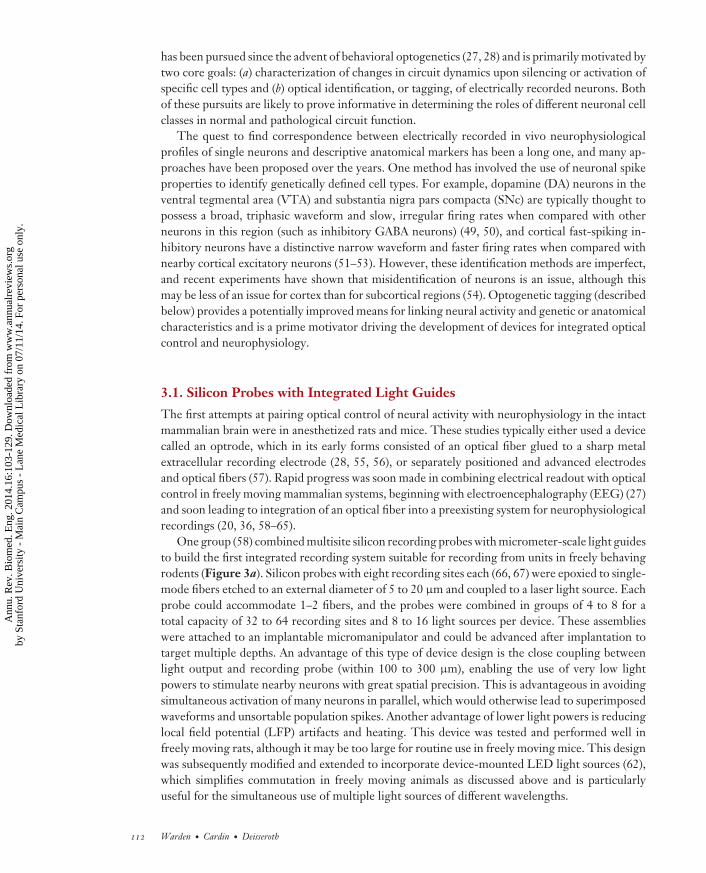
One group (58) combined multisite silicon recording probes with micrometer-scale light guidesto build the first integrated recording system suitable for recording from units in freely behavingrodents (Figure 3a). Silicon probes with eight recording sites each (66, 67) were epoxied to single-mode fibers etched to an external diameter of 5 to 20 μm and coupled to a laser light source. Eachprobe could accommodate 1–2 fibers, and the probes were combined in groups of 4 to 8 for atotal capacity of 32 to 64 recording sites and 8 to 16 light sources per device. These assemblieswere attached to an implantable micromanipulator and could be advanced after implantation totarget multiple depths. An advantage of this type of device design is the close coupling betweenlight output and recording probe (within 100 to 300 μm), enabling the use of very low lightpowers to stimulate nearby neurons with great spatial precision. This is advantageous in avoidingsimultaneous activation of many neurons in parallel, which would otherwise lead to superimposedwaveforms and unsortable population spikes. Another advantage of lower light powers is reducinglocal field potential (LFP) artifacts and heating. This device was tested and performed well infreely moving rats, although it may be too large for routine use in freely moving mice. This designwas subsequently modified and extended to incorporate device-mounted LED light sources (62),which simplifies commutation in freely moving animals as discussed above and is particularlyuseful for the simultaneous use of multiple light sources of different wavelengths.
112 Warden · Cardin · Deisseroth
Ann
u. R
ev. B
iom
ed. E
ng. 2
014.
16:1
03-1
29. D
ownl
oade
d fr
om w
ww
.ann
ualr
evie
ws.
org
by S
tanf
ord
Uni
vers
ity -
Mai
n C
ampu
s -
Lan
e M
edic
al L
ibra
ry o
n 07
/11/
14. F
or p
erso
nal u
se o
nly.

BE16CH05-Warden ARI 28 May 2014 11:44
Electrodeinterface
board
Drivebody
DrivespringElectrode
array
16 drivescrews
a
b
~22 mmhead to cap
Total weight~2 g
c
Optic fiber
Optic fiber
100 μm
16-channelconnector (×2)
1mm
Headstageconnector
Cannula
200 μm
dd
Figure 3Integrated neurophysiology and optical control. (a) Optical fibers can be incorporated into multisite siliconprobe designs suitable for use in freely behaving rats. (Panel modified with permission from 58.) (b) A tetrodemicrodrive with independently drivable tetrodes can be modified to incorporate either a fixed or freelymovable optical fiber for use in large, superficial brain regions such as cortex or the hippocampus. (Panelmodified with permission from 63.) (c) Simultaneous optical stimulation and electrical recording from small,deep structures, such as the brainstem neuromodulatory nuclei, requires a more compact design. A drivabledevice achieves this with tetrodes attached to a central fiber core. (Panel modified with permission from 61.)(d ) An optical fiber can replace an electrode on a multielectrode array to enable simultaneous opticalstimulation and high-density cortical recording. (Panel modified with permission from 65.)
3.2. Stereotrode and Tetrode Microdrives
Other groups have combined fiberoptic light delivery with stereotrode (68) or tetrode (69–71)devices and drives of various designs. One stereotrode device developed for use in freely behavingmice (59) was composed of a fixed optical fiber glued to an electrode interface board (EIB) andsurrounded by eight fixed stereotrodes. This device was later improved by incorporating indepen-dent drives for each tetrode or stereotrode (60), enabling fine control over the position of each
www.annualreviews.org • Optical Neural Interfaces 113
Ann
u. R
ev. B
iom
ed. E
ng. 2
014.
16:1
03-1
29. D
ownl
oade
d fr
om w
ww
.ann
ualr
evie
ws.
org
by S
tanf
ord
Uni
vers
ity -
Mai
n C
ampu
s -
Lan
e M
edic
al L
ibra
ry o
n 07
/11/
14. F
or p
erso
nal u
se o
nly.

BE16CH05-Warden ARI 28 May 2014 11:44
and the ability to gather higher-quality data with more isolatable single units. Although this deviceused a fixed rather than drivable fiber, this configuration may enable more stable recordings. It isworth noting that the kind of optical fiber used in these devices has an outer diameter 10 timesas large as that of an individual stereotrode or electrode and would likely be capable of someamount of local tissue damage through either blunt trauma or rupture of blood vessels, in additionto the tissue deformation that would impair isolation on nearby channels. Most recently, somereengineering led to a device with reduced weight (2 g) and enhanced channel count (16 tetrodes)that can accommodate either a fixed or a movable fiber (63) (Figure 3b).
Another group (61) took an entirely distinct approach, choosing instead to situate at the core ofthe device a movable optical fiber, which was then surrounded by attached tetrodes (Figure 3c). Asa consequence, the whole optetrode assembly could move up and down in brain tissue as a bundle,which is advantageous for maintaining close positioning of the tip of the fiber and the recordingsites—particularly useful for recording in small, deep nuclei. In a typical tetrode hyperdrive (69),tetrodes are free to emerge from different sites at the base of the device and have a tendency todiverge as they are driven into the brain; this adjustable hyperdrive approach is useful for samplingrecording sites in large brain areas, such as the dorsal hippocampus, but falls short when recordingfrom smaller, deeper structures such as the VTA, where light-mediated identification of neuraltype would be especially useful (54). The optetrode device is particularly lightweight at 2 g andwas shown to be suitable for routine use in freely behaving mice (61).
3.3. Fixed-Wire Arrays
Other approaches have made use of fixed-wire implanted arrays. The chronic multisite optrode(CMO) consists of four tungsten wires glued to an implantable fiberoptic light guide (Doric)and cut at 500-μm intervals (20). This device is most suited for LFP and multiunit recordingsand is relatively inexpensive and simple to make within the lab. Also, its small size enables useof more than one device per mouse. However, because of the potential for an optoelectronicartifact introduced by pulsed light (72, 73), this device is best used with opsins that do not requirecontinuous light input, such as the SFOs (13, 20).
3.4. Multielectrode Arrays
Finally, an integrated fiber–multielectrode array (MEA) device, the optrode-MEA, has been de-veloped for chronic recording and stimulation in freely moving rodents (64) (Figure 3d ). In thissetup, 10 × 10 intracortical microelectrode arrays (Blackrock Microsystems) were repurposed toinclude a single tapered optical fiber in place of one of the electrodes. This optical fiber was coatedwith gold and insulated with epoxy, with a small exposed optical aperture at the end, in order topermit simultaneous recording from this site. Achieved impedance measurements ranged from200 k� to 1 M�, within the range typically used for extracellular recordings. The optrode wasstrong enough to penetrate rat dura without deformation, enabling high-quality recordings fromcortical areas. Improvements in this device have been shown to permit chronic recordings of upto 8 months in rat cortex (65) (Figure 3d ), which would be useful for long-term experimentsinvestigating neural plasticity or changes in neural dynamics on this timescale.
Ultimately the choice of device will depend on the application. Optical control in combinationwith arrays of silicon probes or individually controllable tetrode or stereotrode microdrives isideally suited for recording in large regions with dense cell packing, such as the CA1 or CA3pyramidal cell layers in the hippocampus (58, 60, 62, 63). If the desired application is simultaneousrecording of single isolated neurons and stimulation or inhibition in deeper, smaller brain regions,such as the VTA, a unified device with a fiber core is likely more appropriate (61). If cortical
114 Warden · Cardin · Deisseroth
Ann
u. R
ev. B
iom
ed. E
ng. 2
014.
16:1
03-1
29. D
ownl
oade
d fr
om w
ww
.ann
ualr
evie
ws.
org
by S
tanf
ord
Uni
vers
ity -
Mai
n C
ampu
s -
Lan
e M
edic
al L
ibra
ry o
n 07
/11/
14. F
or p
erso
nal u
se o
nly.

BE16CH05-Warden ARI 28 May 2014 11:44
recordings of well-isolated single units over long periods of time are desired, optrode-MEAswould be the best solution, whereas if an inexpensive and simple method for recording corticalLFPs is needed, a chronic multisite optrode would be ideal.
A remaining challenge for optimal functionality of these devices is the optoelectronic artifactalmost always seen in LFP recordings, in which illumination of the metal recording electrodecan produce a significant slow-voltage change (72, 73). In some cases, optical fibers and electricalrecording devices can be separated to avoid this artifact, but this configuration is not practicalfor many applications. This problem may be partially resolved by appropriate configuration oflight delivery and recording electrode, by choice of electrode coating, or by choice of electrodematerial (72).
4. OPTICAL READOUT OF NEURAL ACTIVITY
The past few years have seen an explosion in development of both genetically encodedfluorescence-based indicators of neural activity (74–90) and devices designed to read out these fluo-rescence signals (91–103). Complementing the optical neural activity actuators described above,these optical neural activity reporters enable fast-timescale readout of neural activity, currentlyapproaching the measurement of single neural action potentials (89). Though still under devel-opment, these activity reporters in many respects have the potential to stand alongside electro-physiology as standard tools for measuring neural circuit activity in freely behaving mammals. Invivo fluorescence-based neural activity imaging promises to expand the number of simultaneouslyrecorded neurons by orders of magnitude, to enable the unambiguous mapping of recorded neuralactivity onto underlying genetic or anatomical identity regardless of local circuit architecture, andto provide long-term recording of identified single neurons over days to weeks, allowing investi-gators to probe circuit dynamics during extended processes such as learning or development (104).
4.1. Genetically Encoded Activity Indicators
Genetically encoded activity indicators can report as fluorescence changes certain neuronal prop-erties that are influenced by neural activity, such as intracellular Ca2+ or transmembrane voltage.These indicators have some significant advantages over chemicals such as bulk-loaded Ca2+ orvoltage-sensitive fluorescent dyes, which can be quite fast and sensitive but do not typically allowfor cell-type-specific imaging [although retrogradely and anterogradely transported indicatorscan certainly be used for neural projection-specific labeling (105, 106), and indicators can be usedin combination with cell-type-specific fluorescent labels (107)]. In addition, these dyes must beloaded at the beginning of each imaging session, making chronic neural activity recordings bythis means problematic. By contrast, genetically encoded indicators can be cell-type specific andexhibit persistent expression, enabling monitoring of the same neural population over weeks. Likemicrobial opsins, these genetically encoded sensors can be introduced into neurons using a varietyof methods, including viral vectors (84, 108) and mouse transgenesis (109, 110).
Genetically encoded Ca2+ indicators (GECIs) have made great strides in recent years throughmany iterations of optimization (74–89). These engineered proteins, which typically includeboth green fluorescent protein (GFP)-based components and Ca2+-binding domains (83), reportchanges in local Ca2+ concentration as changes in fluorescence. Action potentials and synaptic in-put trigger Ca2+ influx into neurons over well-studied spatial distributions (111, 112), and GECIscan be used to report changes in these processes. The first GECI constructs had a signal-to-noiseratio that could be used to monitor bursts of action potentials, but not single spikes, whereas mod-ern variants (optimized to be faster and more stable with improved signal-to-noise ratio) are fast
www.annualreviews.org • Optical Neural Interfaces 115
Ann
u. R
ev. B
iom
ed. E
ng. 2
014.
16:1
03-1
29. D
ownl
oade
d fr
om w
ww
.ann
ualr
evie
ws.
org
by S
tanf
ord
Uni
vers
ity -
Mai
n C
ampu
s -
Lan
e M
edic
al L
ibra
ry o
n 07
/11/
14. F
or p
erso
nal u
se o
nly.

BE16CH05-Warden ARI 28 May 2014 11:44
closing in on the goal of discriminating individual action potentials in vivo (89). One caveat is thatCa2+ signals may vary significantly across cell types owing to differences in ion channel expression,Ca2+-binding protein expression, and other regulatory biochemical pathways, but many currentlyavailable Ca2+ indicators have been fully characterized only in excitatory pyramidal neurons.
Progress has also been made in modifying these proteins to fluoresce at different wavelengths,including in the red and blue spectral bands (80, 82, 113–115), which may eventually facilitateboth dual-wavelength fluorescent imaging (for simultaneously imaging two different neuronal celltypes) and combined imaging/optogenetic control, discussed below. Other constructs have beendeveloped for optically reporting the release of specific neurotransmitters (90, 116), which mayeventually complement technologies such as microdialysis (117, 118) or fast-scan cyclic voltam-metry (119, 120). There has also been progress on the development of genetically encoded voltageindicators (GEVIs), which may ultimately enable monitoring of single spikes and subthresholdmembrane potential in vivo (121–129), although improved signal strength and specificity areneeded.
4.2. Population Monitoring with Single Fibers and Fiber Bundles
The development of hardware designed to image neural activity in freely moving mammals hasproceeded in parallel with the development of genetically encoded activity indicators. These de-vices tend to be designed for certain broad categories of experiment: monitoring of bulk populationneural activity (without cellular resolution), two-photon cellular imaging, and one-photon cellularimaging. These designs have most often been validated with chemical activity indicators, but recentwork has seen a greater emphasis on integration with the genetically encoded activity indicatorsdescribed above.
One recent focus has been on detection of bulk population neural activity using single fibersor fiber bundles (91–96). These relatively low-cost techniques have been used with success tostudy cortical Ca2+ waves, investigate the neural dynamics of whisker touch, and probe the circuitmechanisms underlying action initiation in the striatum (91–96). Rather than detecting the activ-ity of single neurons, as with one-photon and two-photon head-mounted microscopy (discussedbelow), these lower-resolution detection and imaging approaches instead monitor total fluores-cence changes driven by the activity of populations of neurons (130, 131) through a single fiberor bundle of fibers implanted over the brain structure of interest, often without the use of on-board microscopy. Correlated activity among relatively large groups of neurons produces a signalthat can be measured using these methods, but these approaches are less useful for monitoringdecorrelated population activity or the activity of small groups of rare neurons (91). Fiber-basedmethods are particularly straightforward for freely behaving rodent models because the flexibil-ity and low weight of the implanted fiber or fiber bundle do not greatly interfere with naturalbehavior.
Early development of these in vivo population–recording fiber methods preceded thewidespread use of GECIs and relied instead on bulk-loaded Ca2+- or voltage-sensing dyes (132).First used in anesthetized preparations (133, 134), this method was quickly extended to freelymoving mammalian systems. One group measured cortical Ca2+ waves in newborn mice using asingle implanted multimode fiber for both excitation and detection (91). A Ca2+ dye was injectedinto cortex, and a 200-μm, 0.48-NA multimode fiber implanted over the same region. Photoncollection was performed using a single photomultiplier tube (PMT), which enabled detection ofbulk fluorescence intensity over time from a single cortical site, as well as observation of spon-taneous cortical Ca2+ transients in the behaving mouse. Experiments in vitro with simultaneousbulk fiber imaging and two-photon imaging showed that signals detectable using this method
116 Warden · Cardin · Deisseroth
Ann
u. R
ev. B
iom
ed. E
ng. 2
014.
16:1
03-1
29. D
ownl
oade
d fr
om w
ww
.ann
ualr
evie
ws.
org
by S
tanf
ord
Uni
vers
ity -
Mai
n C
ampu
s -
Lan
e M
edic
al L
ibra
ry o
n 07
/11/
14. F
or p
erso
nal u
se o
nly.

BE16CH05-Warden ARI 28 May 2014 11:44
100 μm
Wires
Single-modefiber
PMT
Emission filter
Metal plate
Neocortex
XY-scanner
Collimator
Dichroicmirror
MotorObjective
Skull
473-nm ps-pulsed laser
Polychromator
16-channel PMT array
TC
SP
C m
od
ule
a b
c Wirebundle CMOS
camera
Emissionfilter
Collectorlens
LED
Excitationfilter
Objective
Focusingmechanism
Achromatlens
Dichroicmirror
d
Hind-limb stimulation
ObjectiveFiber bundle
Corticalsurface
ROI
Drugs
125 μm125 μm
Imagingarea
L5 pyramidalcells
Right-anglemicroprism
Fiberbundle
Rat
OGB-1 AM
e
10s
5%ΔF/F
Figure 4Optical-neural interfaces for readout of neural signals. Several approaches have been developed for optically monitoring neural signalsin freely behaving mammals. (a) Fiber-based bulk tissue optical recording. A single multimode optical fiber is implanted over a brainarea of interest in order to record fluorescence signals from neurons expressing genetically encoded Ca2+ or voltage indicators. Thissystem is particularly suitable for use in freely behaving mice owing to the small form factor and minimal weight of the implanted fiber.(Panel modified with permission from 96.) (b) One-photon imaging through a fiber bundle permits the construction of population-scaletwo-dimensional images, which can be used to monitor layer-specific neural activity. (Panel modified with permission from 93a.)(c) Head-mounted two-photon microscopy suitable for imaging cellular-resolution cortical fluorescence signals in behaving rats (97).(d ) A lightweight one-photon endoscopic microscopy system that can be used to image cellular-resolution neural activity in deepstructures in behaving mice. (Panel modified with permission from 101.) (e) Ca2+-imaging data collected with the system depicted inpanel d. (top) CA1 principal neurons identified by Ca2+ imaging. (bottom) Ca2+ signals recorded from this neural population in a freelybehaving mouse. (Panel modified with permission from 146.) Abbreviations: CMOS, complementary metal-oxide semiconductor; F,fluorescence; LED, light-emitting diode; OGB-1 AM, Oregon Green 488 BAPTA-1; PMT, photomultiplier tube; ROI, region ofinterest; TCSPC, time-correlated single-photon counting.
represented activity of thousands of cortical neurons, whereas asynchronous Ca2+ transients werenot detectable by fiber (91). Another group used a similar single-fiber bulk detection method tostudy striatal pathways in action initiation (96) (Figure 4a). This study targeted GCaMP3 (84), aGFP- and calmodulin-based GECI, to neurons belonging to the direct or indirect pathways of thestriatum, using a single-mode fiber to deliver excitation pulses and a multimode fiber for detection.
www.annualreviews.org • Optical Neural Interfaces 117
Ann
u. R
ev. B
iom
ed. E
ng. 2
014.
16:1
03-1
29. D
ownl
oade
d fr
om w
ww
.ann
ualr
evie
ws.
org
by S
tanf
ord
Uni
vers
ity -
Mai
n C
ampu
s -
Lan
e M
edic
al L
ibra
ry o
n 07
/11/
14. F
or p
erso
nal u
se o
nly.

BE16CH05-Warden ARI 28 May 2014 11:44
A 473-nm picosecond-pulsed laser was used for excitation, a 16-channel PMT array was used fordetection, and a time-correlated single-photon counting (TCSPC) module was used for photoncounting, together enabling a quantitative description of neural activity in these two cell popula-tions aligned with behavioral events in behaving mice. This method has recently been extendedto permit monitoring of projection-specific neuronal firing (94). These single-fiber methods, byutilizing bulk detection of emitted light rather than cellular-resolution imaging, provide a low-cost complement to optogenetic control in freely behaving mammals and are made particularlypowerful by the concomitant use of genetically encoded fluorescent activity indicators.
Fiber bundles have also been used to measure evoked fluorescence changes. One approach useda 300 × 300 bundle of small (8-μm) single-mode fibers with a voltage-sensitive dye in mice (92).This design, unlike the single-fiber approaches described above, allowed for the reconstruction oftwo-dimensional (2D) fluorescent signal maps from a patch of cortical tissue over time, though notdetection of signals from individual identified neurons. Excitation and imaging were performedthrough the same bundle of fibers. Although the fiber bundle was relatively large (with a diameterof several millimeters), free movement and natural behavior in mice were possible because thecomponent fibers were left unglued and free to flex in the middle of the bundle. This techniquewould be most appropriate for surface cortical recordings because the bundle size would likelycause too much tissue damage in accessing deep brain structures, although as with hippocampalimaging, overlying cortex can be aspirated to image underlying structures in vivo.
Advancements in fiber bundle imaging enabled imaging of dendritic Ca2+ signals in rat cortex(93, 93a) (Figure 4b). This design also utilized a bundle of small single-mode fibers, but in this casethe bundle was attached to a gradient refractive index (GRIN) lens with a right-angle microprismat the end. This cortical periscope was implanted in the upper cortical layers, enabling transverseimaging of the superficial dendrites of deep cortical neurons following layer 5 (L5) loading ofCa2+ indicator. This positioning allowed the investigators to measure population Ca2+ signalsspecifically from the distal dendritic tufts of L5 neurons without signal contamination from deepercortical layers. One group (95) recently reported, for use in mice, an adaptation of this device inwhich GECIs were used instead of bulk-loaded dyes, opening the door to observing the activityof specific populations of genetically defined neurons.
Future experiments using this technology are likely to focus primarily on the use of geneticallyencoded fluorescent activity indicators, rather than bulk-loaded dyes. Dyes are typically useful inexperiments for which neural activity is imaged for a few minutes to hours following dye injectionand device implantation, whereas genetically encoded indicators enable repeated imaging of thesame brain structure after implantation over days to weeks. Choice of a single fiber or fiber bundledepends on application, but single-fiber implementations are particularly attractive for off-the-shelf setup, low cost, and minimal effects on movement in the freely behaving rodent.
4.3. Cellular Imaging with Head-Mounted Two-Photon Microscopy
A prime goal of systems neuroscience is to read out neural activity—ideally at high enough temporaland spatial resolution to detect single action potentials in individual neurons, but with sufficientscope to encompass hundreds to thousands of genetically identified neurons spanning the relevantneural circuits in freely behaving animals. Cellular-resolution one-photon and two-photon head-mounted intracranial microscopies bring the field closer to achieving this goal (102, 103).
Imaging neural activity in the brain is complicated by strong light scattering and absorption inneural tissue (135, 136). One-photon microscopy generally cannot be used to image the activity ofsingle neurons deeper than 50–100 μm (99, 137) because of these factors, but two-photon imaging(135, 136, 138) makes use of near-infrared excitation wavelengths that can penetrate farther into
118 Warden · Cardin · Deisseroth
Ann
u. R
ev. B
iom
ed. E
ng. 2
014.
16:1
03-1
29. D
ownl
oade
d fr
om w
ww
.ann
ualr
evie
ws.
org
by S
tanf
ord
Uni
vers
ity -
Mai
n C
ampu
s -
Lan
e M
edic
al L
ibra
ry o
n 07
/11/
14. F
or p
erso
nal u
se o
nly.

BE16CH05-Warden ARI 28 May 2014 11:44
neural tissue and excite only a small volume at the focal plane, enabling imaging at depths ofup to 500 μm (139, 140) with superior resolution, reduced background fluorescence, and greaterrobustness to scattering. This is a significant improvement, but it comes at a cost of scanningtime (in part addressed by recent advances in resonance scanning) and a smaller field of view, asdiscussed below. Other challenges associated with the application of these technologies to freelybehaving mammals include miniaturization of microscopy hardware and minimization of motionartifacts (which can arise from movements of imaging hardware relative to the skull and/or brainpulsation, presenting considerable difficulties in the behaving animal). Some of these problemsmay be avoided by imaging in head-fixed animals, but this approach currently precludes the useof many standard laboratory behavioral tests.
A miniaturized head-mountable scanning two-photon microscope for use in freely behavingrats (97) (Figure 4c) weighed in at 25 g and spanned 7.5 cm, which is large but not exceedingstandard dimensions of the tetrode hyperdrive in common use for high-density single unit neuro-physiological recordings in behaving rats. As in standard two-photon microscopy, near-infraredexcitation light was provided by a Ti:Sapphire laser, but in this design the light was coupled toa 2-m flexible single-mode optical fiber tether for transport to the head-mounted hardware; thetether also contained electrical lines for power and data transmission. The fiber was mounted on aminiature piezoelectric plate that could be driven at the resonant frequency of the fiber (typically300–800 Hz), causing vibration of the fiber tip and enabling scanning of the focal spot acrossneural tissue. A stiffening rod was added along one side of the fiber, creating two orthogonalresonant frequencies. The piezoelectric plate could be driven with a superposition of these twofrequencies, enabling 2D scanning in a Lissajous pattern across a patch of neural tissue; a singleresonant frequency could be used for higher-resolution line scanning. The actual movement ofthe fiber tip was phase-shifted from the driver, requiring calibration before implantation and ex-perimentation. Excitation and barrier filters, a dichroic mirror, imaging lenses, and a PMT wereadditionally miniaturized and contained within the housing of the head-mounted hardware, whichwas mounted above a cranial window. As only a small volume of neural tissue was excited at anygiven time, all of the emitted light from this focal spot could be collected by the PMT and assignedto the correct pixel to produce an image. With this design, it was possible to image 200–250 μmbelow the cortical surface in L2/3, to resolve dendritic features, and to measure dendritic Ca2+
transients in the awake behaving rat. Although imaging quality was quite good with this system,significant motion artifacts were encountered; imaging during slow movement and rest was possi-ble, but quick head movements led to permanent shifts in imaging frame, limiting utility for somebehavioral paradigms.
Motion artifacts are a crucial issue in behaving two-photon microscopy (both freely movingand head-fixed) and are exacerbated by the relatively small field of view and long scan times ofthis imaging modality (97). These artifacts may arise from device movement relative to the skull,heartbeat, breathing, licking, and animal motion, all of which interfere with image acquisition(141–144). There has been recent progress toward minimization of these artifacts using heartbeat-triggered scanning (143), licking correction with a tunable lens (144), and an adaptive imaging-based movement compensation system (142). Although much of this movement compensationhas been developed in head-fixed or anesthetized preparations, application of these technologicalinnovations to head-mounted imaging should enable higher-quality data acquisition.
The development of endoscopic two-photon imaging in freely moving mice (98) representeda key advance, enabling deep-brain two-photon imaging—importantly, in a genetically tractableanimal. Fluorescence microendoscopy can be used with either one- or two-photon excitation forimaging of deep tissues, typically with compound GRIN lens–based microendoscopic probes.This approach was initially tested in head-fixed animals (102, 145) and then incorporated into
www.annualreviews.org • Optical Neural Interfaces 119
Ann
u. R
ev. B
iom
ed. E
ng. 2
014.
16:1
03-1
29. D
ownl
oade
d fr
om w
ww
.ann
ualr
evie
ws.
org
by S
tanf
ord
Uni
vers
ity -
Mai
n C
ampu
s -
Lan
e M
edic
al L
ibra
ry o
n 07
/11/
14. F
or p
erso
nal u
se o
nly.

BE16CH05-Warden ARI 28 May 2014 11:44
elegant devices suitable for freely moving mice (98). The latter application was made possible by asignificant reduction in device mass and size but used the same basic strategy for optical scanning—fiber vibrated in a Lissajous pattern, enabling scan fields spanning 145 to 215 μm. Reduction insize was due largely to replacing internal optics with small lightweight GRIN lenses, and spatialresolution was increased by using a flexible photonic bandgap fiber with an air core, rather thana single-mode fiber, for carrying the excitation light (this modification enables transmission ofultrashort pulses free of distortion). The lack of an onboard PMT also aided in weight reduction;emitted photons were collected instead by a multimode fiber for detection on the bench top. Thedevice had a lateral resolution of 1.21 μm and an axial resolution of 9.8 μm, which represent asignificant advance enabling definition of single neuronal cell bodies in vivo.
4.4. Cellular Imaging with Head-Mounted One-Photon Microscopy
Rapid progress has been made in miniaturization of one-photon epifluorescence imaging hardwarefor freely behaving mammals and has already led to key scientific results that would not have beenpossible with standard neurophysiological techniques (101, 146). Penetration depths are not asgood as with two-photon microscopy (discussed above), but the faster frame rates characteristic ofone-photon imaging reduce motion artifacts and greatly facilitate cellular imaging during naturalbehavior.
An early version of this kind of microscope (99), weighing only 1.1 g and therefore suitable foruse in behaving mice, allowed imaging of single neurons during natural behavior at frame ratesup to 100 Hz. This major weight reduction was made possible by moving most of the hardware,including illumination source and detector, filters, and dichroic mirror, off the animal and ontothe tabletop; only three GRIN lenses and a focusing motor were mounted directly on the mouse.Light was transported to and from the animal by a high-density fiber bundle, which was coupled toan optical commutator for freedom of movement. The device was designed to make use of either1.4-mm or 6.2-mm endoscopic GRIN lens objectives, which could be used for surface or deepimaging, respectively. It was possible to obtain a 240–370-μm field of view, with lateral resolutionof ∼2.8 μm and 10-μm depth of field, which were stable through normal movement. With thisdevice, Ca2+ transients could be imaged in the dendritic arbors of individual cerebellar Purkinjeneurons.
A significant advance toward commercialization and widespread use of this technology wasachieved a few years later (101) (Figure 4d ). Although the concept of this device was similar tothe one-photon epifluorescence microscope described above, almost everything in this instantia-tion was moved to the head-mounted hardware, without a prohibitive increase in weight (1.9 g).Using an integrated light source (a blue LED), excitation filter, dichroic mirror, objective, bar-rier filter, focusing mechanism, and complementary metal-oxide semiconductor (CMOS) cameraenabled the use of only-electrical leads to the animal for power and data transmission in thetether—a significant advance for greatest flexibility. In addition, the device was made largely frommass-producible parts, including the semiconductor light source and camera, which may enablewidespread, low-cost use in the field. The microscope can be used to image individual neuronsfrom freely behaving mice in a field of view of 600 to 800 μm with lateral resolution of 2.5 μm,and it can be run at 36 or 100 frames per second, allowing the acquisition of high-quality neuralpopulation data.
An initial application of this microscope was to image Ca2+ transients in over 200 simulta-neously recorded Purkinje neurons, in the process identifying previously unsuspected high-ordercorrelations in up to 30 neurons, organized by cerebellar microzone, during motor behavior(101). Subsequent experiments yielded equally surprising results in the CA1 subfield of the dorsal
120 Warden · Cardin · Deisseroth
Ann
u. R
ev. B
iom
ed. E
ng. 2
014.
16:1
03-1
29. D
ownl
oade
d fr
om w
ww
.ann
ualr
evie
ws.
org
by S
tanf
ord
Uni
vers
ity -
Mai
n C
ampu
s -
Lan
e M
edic
al L
ibra
ry o
n 07
/11/
14. F
or p
erso
nal u
se o
nly.

BE16CH05-Warden ARI 28 May 2014 11:44
hippocampus (146) (Figure 4e). In this series of experiments, the authors tracked thousands ofplace cells over several weeks in freely behaving mice, with yield an order of magnitude higherthan typical neurophysiological recordings with tetrode hyperdrives. With this new technology,long-term stochasticity in place field expression was observed that would not be detected withstandard electrophysiological techniques, as it is generally not possible to record the activity of asingle identified neuron over the course of several days. With cellular-resolution imaging, how-ever, frames could be spatially registered from day to day with certainty of neural identification,enabling true long-term monitoring of neuronal activity. Although place fields of individual mon-itored neurons did not change with time, cells fluctuated between active participation in placecoding and quiescence on a daily basis. Two-photon and one-photon imaging in freely movingmammalian systems each possess key advantages, but one-photon microscopy is currently morerobust to imaging disruptions caused by animal movement. Although it is not possible to imagemore than 100 μm deep into neural tissue with this technology, this limitation has not provedprohibitive for the demonstration of new and important scientific results.
5. FUTURE DIRECTIONS
Promising domains of exploration in the coming years will involve development of advancedoptical neural interfaces for increasingly sophisticated research applications. And beyond basicscience applications, clinically inspired devices such as peripheral nerve cuff optogenetic devicesdesigned to wrap around nerves (much like the vagus nerve stimulation cuffs used for epilepsyand depression, but with LED outputs instead of electrode contact outputs) are being tested inanimal models (147–149) and may in the long run even lead to clinically applicable optical neuralinterfaces.
In the basic science realm, important long-term directions for optical control devices includefast 3D cellular-resolution, spatially addressable light patterning, minimization of optoelectronicartifacts, advanced development of LEDs and other light-generation technologies, and higher-powered wireless control. Long-term goals for optical readout devices include faster and deeperimaging with higher resolution, improved image stability during free behavior, and reliable single-spike detection in vivo during behavior. And integrative optical neural interfaces for combinedimaging and control will be a major area of further development, as all-optical interrogation ofneural activity is likely to powerfully advance the implementation of sophisticated closed-loopexperimental designs for flexible and precise read-write circuit-level control in freely behavingmammals.
In the simplest forms of such an integrative all-optical system, fiber-based population measure-ments may be combined with optical control using the same implanted probe for imaging and lightdelivery; the input and output optical channels must be separable, but progress along this fronthas already taken steps through development of spectrally shifted optical indicators and actuators(12, 20, 25, 80, 82, 113). However, the excitation spectrum of GCaMP6 probes (89) (perhaps thebest currently available family of GECIs) substantially overlaps the activation spectra of ChR2(8, 10), C1V1 (ChR1/VChR1 chimaera) (20, 21), NpHR (9, 11), and Arch (archaerhodopsin-3from Halorubrum sodomense) (15, 21), the most effective optogenetic control tools. Compoundingthis challenge in combining imaging and optogenetics is overload of imaging PMTs when opsinsare stimulated (as they typically would be) at much higher power than is required for imaging.One approach to this problem with combining readout and control would be to use the SFOChR derivatives, which confer orders-of-magnitude-increased light sensitivity to expressing cells(19–21). Although the most sensitive SFO tools have not yet been applied in this context in freelybehaving mammals, a T159C ChR mutant that confers higher light sensitivity on expressing cells
www.annualreviews.org • Optical Neural Interfaces 121
Ann
u. R
ev. B
iom
ed. E
ng. 2
014.
16:1
03-1
29. D
ownl
oade
d fr
om w
ww
.ann
ualr
evie
ws.
org
by S
tanf
ord
Uni
vers
ity -
Mai
n C
ampu
s -
Lan
e M
edic
al L
ibra
ry o
n 07
/11/
14. F
or p
erso
nal u
se o
nly.

BE16CH05-Warden ARI 28 May 2014 11:44
while retaining good temporal precision (19, 21) has been applied in combination with RCaMP, anewly developed red GCaMP derivative with the eGFP domain replaced by circularly permutedmRuby (82). These two constructs work well together with minimal cross talk as long as relativelylow light powers are used (e.g., 56 mW/cm2). However, other red-shifted indicators (mApple-derived R-GECO and RCaMP1.07) artifactually photoswitch under intense blue light by alteringred fluorescence even in the absence of Ca2+ changes, and therefore should be combined withoptical actuators only in the setting of appropriate controls (113, 114). Many other highly light-sensitive engineered opsins, and other input/output combinations such as blue/green spectrumGCaMP indicators combined with red-spectrum C1V1-family opsin actuators, should be exploredwith this motivation (21). These issues underscore that it will be essential for the developmentof optical neural interfaces to proceed tightly intertwined with the development of the biologicalwetware and in the setting of the relevant in vivo biological applications.
A final area of growth will be the development of optical neural interfaces that allow not onlyimaging at single-cell resolution but also optical stimulation with single-cell resolution, in freelybehaving mammals. Single-cell optogenetic stimulation has already been achieved in cortex ofliving mice using the C1V1 channelrhodopsin and raster-scanning two-photon illumination (150);this kind of setup would already be compatible with behaviors measured in head-fixed mice usingexisting technologies. Next-generation optical interfaces for single-cell-resolution stimulation inbehaving mammals may enable independent control over multiple isolated cells with user-definedtemporal relationships and may be based on digital micromirrors, light field illumination, and/orholographic spatial light modulators (150–152). Miniaturization and adaptation to mammalianbehavioral setups will be crucial fronts in this exciting and expanding field.
In summary, recent years have witnessed the rapid development of paradigm-shifting tech-nologies for both optical control and readout of neural activity in freely moving mammaliansystems. Genetically encoded optical actuators together with devices for intracranial light deliveryhave made it possible to selectively modulate neural activity, and genetically encoded fluorescentindicators and devices for head-mounted imaging have allowed the detection of activity in de-fined populations and individual cells. As the molecular tools and dedicated hardware continueto advance in close association, the transformative opportunities for basic science and preclinicalinvestigation will continue to expand rapidly. These technologies are already enabling ground-breaking discoveries in neuroscience, and defining a new era in the study of neural circuits andbehavior.
DISCLOSURE STATEMENT
M.R.W. and K.D. have disclosed aspects of the work described here to the Stanford Office ofTechnology Licensing, which has filed a patent application for the possible use of the findingsand methods. K.D. is a cofounder of Circuit Therapeutics Inc., which has licensed some of thesetechnologies to develop treatments for peripheral nervous system interventions to treat disease.
ACKNOWLEDGMENTS
The authors acknowledge support from the Wiegers Family Fund (K.D.); NARSAD/Brain & Be-havior Research Foundation (M.R.W., J.A.C., and K.D.); the NIMH, NIDA, NSF, the DARPANeuroFAST and REPAIR Programs, and the Gatsby Charitable Foundation (K.D.); and theNEI, Whitehall Foundation, Klingenstein Foundation, Smith Family Foundation, Alfred P. SloanFoundation, and Simons Foundation ( J.A.C.). M.R.W. is a Robertson Neuroscience Investiga-tor of the New York Stem Cell Foundation. All materials, methods, and reagents remain freely
122 Warden · Cardin · Deisseroth
Ann
u. R
ev. B
iom
ed. E
ng. 2
014.
16:1
03-1
29. D
ownl
oade
d fr
om w
ww
.ann
ualr
evie
ws.
org
by S
tanf
ord
Uni
vers
ity -
Mai
n C
ampu
s -
Lan
e M
edic
al L
ibra
ry o
n 07
/11/
14. F
or p
erso
nal u
se o
nly.

BE16CH05-Warden ARI 28 May 2014 11:44
available for academic and nonprofit research in perpetuity through the Deisseroth Lab optoge-netics website (www.optogenetics.org).
LITERATURE CITED
1. Penfield W, Perot P. 1963. The brain’s record of auditory and visual experience: a final summary anddiscussion. Brain 86(4):595–696
2. Salzman CD, Britten KH, Newsome WT. 1990. Cortical microstimulation influences perceptual judge-ments of motion direction. Nature 346(6280):174–77
3. Mayberg HS, Lozano AM, Voon V, McNeely HE, Seminowicz D, et al. 2005. Deep brain stimulationfor treatment-resistant depression. Neuron 45(5):651–60
4. Fenno L, Yizhar O, Deisseroth K. 2011. The development and application of optogenetics. Annu. Rev.Neurosci. 34:389–412
5. Yizhar O, Fenno LE, Davidson TJ, Mogri M, Deisseroth K. 2011. Optogenetics in neural systems.Neuron 71(1):9–34
6. Knopfel T. 2012. Genetically encoded optical indicators for the analysis of neuronal circuits. Nat. Rev.Neurosci. 13(10):687–700
7. Looger LL, Griesbeck O. 2012. Genetically encoded neural activity indicators. Curr. Opin. Neurobiol.22(1):18–23
8. Boyden ES, Zhang F, Bamberg E, Nagel G, Deisseroth K. 2005. Millisecond-timescale, geneticallytargeted optical control of neural activity. Nat. Neurosci. 8(9):1263–68
9. Zhang F, Wang L-P, Brauner M, Liewald JF, Kay K, et al. 2007. Multimodal fast optical interrogationof neural circuitry. Nature 446(7136):633–39
10. Nagel G, Ollig D, Fuhrmann M, Kateriya S, Musti AM, et al. 2002. Channelrhodopsin-1: a light-gatedproton channel in green algae. Science 296(5577):2395–98
11. Han X, Boyden ES. 2007. Multiple-color optical activation, silencing, and desynchronization of neuralactivity, with single-spike temporal resolution. PLoS ONE 2(3):e299
12. Zhang F, Prigge M, Beyriere F, Tsunoda SP, Mattis J, et al. 2008. Red-shifted optogenetic excitation:a tool for fast neural control derived from Volvox carteri. Nat. Neurosci. 11(6):631–33
13. Berndt A, Yizhar O, Gunaydin L, Hegemann P, Deisseroth K. 2009. Bi-stable neural state switches.Nat. Neurosci. 12(2):229–34
14. Gradinaru V, Zhang F, Ramakrishnan C, Mattis J, Prakash R, et al. 2010. Molecular and cellularprinciples for diversifying and extending optogenetics. Cell 141:1–12
15. Chow BY, Han X, Dobry AS, Qian X, Chuong AS, et al. 2010. High-performance genetically targetableoptical neural silencing by light-driven proton pumps. Nature 463(7277):98–102
16. Lin JY, Lin MZ, Steinbach P, Tsien RY. 2009. Characterization of engineered channelrhodopsinvariants with improved properties and kinetics. Biophys. J. 96(5):1803–14
17. Wang H, Sugiyama Y, Hikima T, Sugano E, Tomita H, et al. 2009. Molecular determinants dif-ferentiating photocurrent properties of two channelrhodopsins from Chlamydomonas. J. Biol. Chem.284(9):5685–96
18. Gunaydin L, Yizhar O, Berndt A, Sohal VS, Deisseroth K, Hegemann P. 2010. Ultrafast optogeneticcontrol. Nat. Neurosci. 13(3):387–92
19. Berndt A, Schoenenberger P, Mattis J, Tye KM, Deisseroth K, et al. 2011. High-efficiency channel-rhodopsins for fast neuronal stimulation at low light levels. Proc. Natl. Acad. Sci. USA 108(18):7595–600
20. Yizhar O, Fenno LE, Prigge M, Schneider F, Davidson TJ, et al. 2011. Neocortical excitation/inhibitionbalance in information processing and social dysfunction. Nature 477(7363):171–78
21. Mattis J, Tye KM, Ferenczi E, Ramakrishnan C, O’Shea DJ, et al. 2012. Principles for applying opto-genetic tools derived from direct comparative analysis of microbial opsins. Nat. Methods 9(2):159–72
22. Zemelman BV, Lee GA, Ng M, Miesenbock G. 2002. Selective photostimulation of genetically chargedneurons. Neuron 33(1):15–22
23. Banghart M, Borges K, Isacoff E, Trauner D, Kramer RH. 2004. Light-activated ion channels forremote control of neuronal firing. Nat. Neurosci. 7(12):1381–86
www.annualreviews.org • Optical Neural Interfaces 123
Ann
u. R
ev. B
iom
ed. E
ng. 2
014.
16:1
03-1
29. D
ownl
oade
d fr
om w
ww
.ann
ualr
evie
ws.
org
by S
tanf
ord
Uni
vers
ity -
Mai
n C
ampu
s -
Lan
e M
edic
al L
ibra
ry o
n 07
/11/
14. F
or p
erso
nal u
se o
nly.

BE16CH05-Warden ARI 28 May 2014 11:44
24. Lima SQ, Miesenbock G. 2005. Remote control of behavior through genetically targeted photostimu-lation of neurons. Cell 121(1):141–52
25. Prigge M, Schneider F, Tsunoda SP, Shilyansky C, Wietek J, et al. 2012. Color-tuned channel-rhodopsins for multiwavelength optogenetics. J. Biol. Chem. 287(38):31804–12
26. Nagel G, Brauner M, Liewald JF, Adeishvili N, Bamberg E, Gottschalk A. 2005. Light activation ofchannelrhodopsin-2 in excitable cells of Caenorhabditis elegans triggers rapid behavioral responses. Curr.Biol. 15(24):2279–84
27. Adamantidis AR, Zhang F, Aravanis AM, Deisseroth K, de Lecea L. 2007. Neural substrates of awak-ening probed with optogenetic control of hypocretin neurons. Nature 450(7168):420–24
27a. Aravanis AM, Wang LP, Zhang F, Meltzer LA, Mogri MZ, et al. 2007. An optical neural interface: invivo control of rodent motor cortex with integrated fiberoptic and optogenetic technology. J. NeuralEng. 4:S143–56
28. Gradinaru V, Thompson KR, Zhang F, Mogri M, Kay K, et al. 2007. Targeting and readout strategiesfor fast optical neural control in vitro and in vivo. J. Neurosci. 27(52):14231–38
29. Zhang F, Gradinaru V, Adamantidis AR, Durand R, Airan RD, et al. 2010. Optogenetic interrogationof neural circuits: technology for probing mammalian brain structures. Nat. Protoc. 5(3):439–56
30. Sparta DR, Stamatakis AM, Phillips JL, Hovelsø N, Van Zessen R, Stuber GD. 2012. Constructionof implantable optical fibers for long-term optogenetic manipulation of neural circuits. Nat. Protoc.7(1):12–23
31. Witten IB, Lin S-C, Brodsky M, Prakash R, Diester I, et al. 2010. Cholinergic interneurons controllocal circuit activity and cocaine conditioning. Science 330(6011):1677–81
32. Tye KM, Prakash R, Kim S-Y, Fenno LE, Grosenick L, et al. 2011. Amygdala circuitry mediatingreversible and bidirectional control of anxiety. Nature 471(7338):358–62
33. Goshen I, Brodsky M, Prakash R, Wallace J, Gradinaru V, et al. 2011. Dynamics of retrieval strategiesfor remote memories. Cell 147(3):678–89
34. Warden MR, Selimbeyoglu A, Mirzabekov JJ, Lo M, Thompson KR, et al. 2012. A prefrontal cortex–brainstem neuronal projection that controls response to behavioural challenge. Nature 492(7429):428–32
35. Tye KM, Mirzabekov JJ, Warden MR, Ferenczi EA, Tsai H-C, et al. 2013. Dopamine neurons modulateneural encoding and expression of depression-related behaviour. Nature 493(7433):537–41
36. Kim S-Y, Adhikari A, Lee SY, Marshel JH, Kim CK, et al. 2013. Diverging neural pathways assemblea behavioural state from separable features in anxiety. Nature 496(7444):219–23
37. Wentz CT, Bernstein JG, Monahan P, Guerra A, Rodriguez A, Boyden ES. 2011. A wirelessly poweredand controlled device for optical neural control of freely-behaving animals. J. Neural Eng. 8(4):046021
38. Clements I, Gnade A, Rush A, Patten C, Twomey M, Kravitz A. 2013. Miniaturized LED sources forin vivo optogenetic experimentation. Proc. SPIE 8586:85860
39. Huber D, Petreanu L, Ghitani N, Ranade S, Hromadka T, et al. 2008. Sparse optical microstimulationin barrel cortex drives learned behaviour in freely moving mice. Nature 451(7174):61–64
40. Bernstein JG, Han X, Henninger M, Ko EY, Qian X, et al. 2008. Prosthetic systems for therapeuticoptical activation and silencing of genetically-targeted neurons. Proc. Soc. Photo-Opt. Instrum. Eng.6854:68540H
41. Iwai Y, Honda S, Ozeki H, Hashimoto M, Hirase H. 2011. A simple head-mountable LED device forchronic stimulation of optogenetic molecules in freely moving mice. Neurosci. Res. 70(1):124–27
42. Bernstein JG, Boyden ES. 2011. Optogenetic tools for analyzing the neural circuits of behavior. TrendsCogn. Sci. 15(12):592–600
43. Zorzos AN, Boyden ES, Fonstad CG. 2010. Multiwaveguide implantable probe for light delivery tosets of distributed brain targets. Opt. Lett. 35(24):4133–35
44. Zorzos AN, Scholvin J, Boyden ES, Fonstad CG. 2012. Three-dimensional multiwaveguide probe arrayfor light delivery to distributed brain circuits. Opt. Lett. 37(23):4841–43
45. Im M, Cho I, Wu F, Wise KD, Yoon E. 2011. Neural probes integrated with optical mixer/splitterwaveguides and multiple stimulation sites. Proc. Int. Conf. Micro Electro Mech. Syst. (MEMS), 24th,Cancun, Mex., Jan. 23–27, pp. 1051–54. New York: IEEE
124 Warden · Cardin · Deisseroth
Ann
u. R
ev. B
iom
ed. E
ng. 2
014.
16:1
03-1
29. D
ownl
oade
d fr
om w
ww
.ann
ualr
evie
ws.
org
by S
tanf
ord
Uni
vers
ity -
Mai
n C
ampu
s -
Lan
e M
edic
al L
ibra
ry o
n 07
/11/
14. F
or p
erso
nal u
se o
nly.

BE16CH05-Warden ARI 28 May 2014 11:44
46. Abaya TVF, Blair S, Tathireddy P, Rieth L, Solzbacher F. 2012. A 3D glass optrode array for opticalneural stimulation. Biomed. Opt. Express 3(12):3087–104
47. Abaya TVF, Diwekar M, Blair S, Tathireddy P, Rieth L, et al. 2012. Characterization of a 3D optrodearray for infrared neural stimulation. Biomed. Opt. Express 3(9):2200–19
48. Kim T-I, McCall JG, Jung YH, Huang X, Siuda ER, et al. 2013. Injectable, cellular-scale optoelectronicswith applications for wireless optogenetics. Science 340(6129):211–16
49. Ungless MA, Grace AA. 2012. Are you or aren’t you? Challenges associated with physiologically iden-tifying dopamine neurons. Trends Neurosci. 35(7):422–30
50. Grace AA, Bunney BS. 1980. Nigral dopamine neurons: intracellular recording and identification withL-dopa injection and histofluorescence. Science 210(4470):654–56
51. Swadlow HA. 1998. Neocortical efferent neurons with very slowly conducting axons: strategies forreliable antidromic identification. J. Neurosci. Methods 79(2):131–41
52. Diester I, Nieder A. 2008. Complementary contributions of prefrontal neuron classes in abstract nu-merical categorization. J. Neurosci. 28(31):7737–47
53. Constantinidis C, Goldman-Rakic PS. 2002. Correlated discharges among putative pyramidal neuronsand interneurons in the primate prefrontal cortex. J. Neurophysiol. 88(6):3487–97
54. Cohen JY, Haesler S, Vong L, Lowell BB, Uchida N. 2012. Neuron-type-specific signals for rewardand punishment in the ventral tegmental area. Nature 482(7383):85–88
55. Gradinaru V, Mogri M, Thompson KR, Henderson JM, Deisseroth K. 2009. Optical deconstructionof parkinsonian neural circuitry. Science 324(5925):354–59
56. Tsai H-C, Zhang F, Adamantidis A, Stuber GD, Bonci A, et al. 2009. Phasic firing in dopaminergicneurons is sufficient for behavioral conditioning. Science 324(5930):1080–84
57. Cardin JA, Carlen M, Meletis K, Knoblich U, Zhang F, et al. 2009. Driving fast-spiking cells inducesgamma rhythm and controls sensory responses. Nature 459(7247):663–67
58. Royer S, Zemelman BV, Barbic M, Losonczy A, Buzsaki G, Magee JC. 2010. Multi-array silicon probeswith integrated optical fibers: light-assisted perturbation and recording of local neural circuits in thebehaving animal. Eur. J. Neurosci. 31(12):2279–91
59. Halassa MM, Siegle JH, Ritt JT, Ting JT, Feng G, Moore CI. 2011. Selective optical drive of thalamicreticular nucleus generates thalamic bursts and cortical spindles. Nat. Neurosci. 14(9):1118–20
60. Siegle JH, Carlen M, Meletis K, Tsai L-H, Moore CI, Ritt J. 2011. Chronically implanted hyperdrivefor cortical recording and optogenetic control in behaving mice. Proc. Annu. Int. Conf. Eng. Med. Biol.Soc. (EMBS), 33rd, Boston, Aug. 30–Sep. 3, pp. 7529–32. New York: IEEE
61. Anikeeva P, Andalman AS, Witten I, Warden M, Goshen I, et al. 2012. Optetrode: a multichannelreadout for optogenetic control in freely moving mice. Nat. Neurosci. 15(1):163–70
62. Stark E, Koos T, Buzsaki G. 2012. Diode probes for spatiotemporal optical control of multiple neuronsin freely moving animals. J. Neurophysiol. 108(1):349–63
63. Voigts J, Siegle JH, Pritchett DL, Moore CI. 2013. The flexDrive: an ultra-light implant for opticalcontrol and highly parallel chronic recording of neuronal ensembles in freely moving mice. Front. Syst.Neurosci. 7:8
64. Wang J, Borton DA, Zhang J, Burwell RD, Nurmikko AV. 2010. A neurophotonic device for stimu-lation and recording of neural microcircuits. Proc. Annu. Int. Conf. Eng. Med. Biol. Soc. (EMBS), 32nd,Buenos Aires, Aug. 31–Sep. 4, pp. 2935–38. New York: IEEE
65. Wang J, Wagner F, Borton D, Zhang J, Ozden I, et al. 2012. Integrated device for combined opticalneuromodulation and electrical recording for chronic in vivo applications. J. Neural Eng. 9(1):016001
66. Csicsvari J, Henze DA, Jamieson B, Harris KD, Sirota A, et al. 2003. Massively parallel recording ofunit and local field potentials with silicon-based electrodes. J. Neurophysiol. 90(2):1314–23
67. Bartho P, Hirase H, Monconduit L, Zugaro M, Harris KD, Buzsaki G. 2004. Characterization ofneocortical principal cells and interneurons by network interactions and extracellular features. J. Neu-rophysiol. 92(1):600–8
68. McNaughton BL, O’Keefe J, Barnes C. 1983. The stereotrode: a new technique for simultaneousisolation of several single units in the central nervous system from multiple unit records. J. Neurosci.Methods 8(4):391–97
www.annualreviews.org • Optical Neural Interfaces 125
Ann
u. R
ev. B
iom
ed. E
ng. 2
014.
16:1
03-1
29. D
ownl
oade
d fr
om w
ww
.ann
ualr
evie
ws.
org
by S
tanf
ord
Uni
vers
ity -
Mai
n C
ampu
s -
Lan
e M
edic
al L
ibra
ry o
n 07
/11/
14. F
or p
erso
nal u
se o
nly.

BE16CH05-Warden ARI 28 May 2014 11:44
69. Wilson M, McNaughton BL. 1993. Dynamics of the hippocampal ensemble code for space. Science261(5124):1055–58
70. Kloosterman F, Davidson TJ, Gomperts SN, Layton SP, Hale G, et al. 2009. Micro-drive array forchronic in vivo recording: drive fabrication. J. Vis. Exp. (26):e1094
71. Nguyen DP, Layton SP, Hale G, Gomperts SN, Davidson TJ, et al. 2009. Micro-drive array for chronicin vivo recording: tetrode assembly. J. Vis. Exp. (26):e1098
72. Cardin JA, Carlen M, Meletis K, Knoblich U, Zhang F, et al. 2010. Targeted optogenetic stimulationand recording of neurons in vivo using cell-type-specific expression of channelrhodopsin-2. Nat. Protoc.5(2):247–54
73. Han X, Qian X, Bernstein JG, Zhou H-H, Franzesi GT, et al. 2009. Millisecond-timescale opticalcontrol of neural dynamics in the nonhuman primate brain. Neuron 62(2):191–98
74. Miyawaki A, Llopis J, Heim R, McCaffery JM, Adams JA, et al. 1997. Fluorescent indicators for Ca2+
based on green fluorescent proteins and calmodulin. Nature 388(6645):882–8775. Persechini A, Lynch JA, Romoser VA. 1997. Novel fluorescent indicator proteins for monitoring free
intracellular Ca2+. Cell Calcium 22(3):209–1676. Romoser VA. 1997. Detection in living cells of Ca2+-dependent changes in the fluorescence emission
of an indicator composed of two green fluorescent protein variants linked by a calmodulin-bindingsequence: a new class of fluorescent indicators. J. Biol. Chem. 272(20):13270–74
77. Nakai J, Ohkura M, Imoto K. 2001. A high signal-to-noise Ca2+ probe composed of a single greenfluorescent protein. Nat. Biotechnol. 19(2):137–41
78. Ohkura M, Matsuzaki M, Kasai H, Imoto K, Nakai J. 2005. Genetically encoded bright Ca2+ probeapplicable for dynamic Ca2+ imaging of dendritic spines. Anal. Chem. 77(18):5861–69
79. Tallini YN, Ohkura M, Choi B-R, Ji G, Imoto K, et al. 2006. Imaging cellular signals in the heartin vivo: cardiac expression of the high-signal Ca2+ indicator GCaMP2. Proc. Natl. Acad. Sci. USA103(12):4753–58
80. Zhao Y, Araki S, Wu J, Teramoto T, Chang Y-F, et al. 2011. An expanded palette of genetically encodedCa2+ indicators. Science 333(6051):1888–91
81. Akerboom J, Chen T-W, Wardill TJ, Tian L, Marvin JS, et al. 2012. Optimization of a GCaMP calciumindicator for neural activity imaging. J. Neurosci. 32(40):13819–40
82. Akerboom J, Carreras Calderon N, Tian L, Wabnig S, Prigge M, et al. 2013. Genetically encodedcalcium indicators for multi-color neural activity imaging and combination with optogenetics. Front.Mol. Neurosci. 6:2
83. Hires SA, Tian L, Looger LL. 2008. Reporting neural activity with genetically encoded calcium indi-cators. Brain Cell Biol. 36(1–4):69–86
84. Tian L, Hires SA, Mao T, Huber D, Chiappe ME, et al. 2009. Imaging neural activity in worms, fliesand mice with improved GCaMP calcium indicators. Nat. Methods 6(12):875–81
85. Tian L, Akerboom J, Schreiter ER, Looger LL. 2012. Neural activity imaging with genetically encodedcalcium indicators. Prog. Brain Res. 196:79–94
86. Tian L, Hires SA, Looger LL. 2012. Imaging neuronal activity with genetically encoded calciumindicators. Cold Spring Harb. Protoc. 2012(6):647–56
87. Dugue GP, Akemann W, Knopfel T. 2012. A comprehensive concept of optogenetics. Prog. Brain Res.196:1–28
88. Alford SC, Wu J, Zhao Y, Campbell RE, Knopfel T. 2013. Optogenetic reporters. Biol. Cell 105(1):14–2989. Chen T-W, Wardill TJ, Sun Y, Pulver SR, Renninger SL, et al. 2013. Ultrasensitive fluorescent proteins
for imaging neuronal activity. Nature 499(7458):295–30090. Marvin JS, Borghuis BG, Tian L, Cichon J, Harnett MT, et al. 2013. An optimized fluorescent probe
for visualizing glutamate neurotransmission. Nat. Methods 10(2):162–7091. Adelsberger H, Garaschuk O, Konnerth A. 2005. Cortical calcium waves in resting newborn mice. Nat.
Neurosci. 8(8):988–9092. Ferezou I, Bolea S, Petersen CCH. 2006. Visualizing the cortical representation of whisker touch:
voltage-sensitive dye imaging in freely moving mice. Neuron 50(4):617–29
126 Warden · Cardin · Deisseroth
Ann
u. R
ev. B
iom
ed. E
ng. 2
014.
16:1
03-1
29. D
ownl
oade
d fr
om w
ww
.ann
ualr
evie
ws.
org
by S
tanf
ord
Uni
vers
ity -
Mai
n C
ampu
s -
Lan
e M
edic
al L
ibra
ry o
n 07
/11/
14. F
or p
erso
nal u
se o
nly.
BE16CH05-Warden ARI 28 May 2014 11:44
93. Murayama M, Perez-Garci E, Luscher H-R, Larkum ME. 2007. Fiberoptic system for recordingdendritic calcium signals in layer 5 neocortical pyramidal cells in freely moving rats. J. Neurophysiol.98(3):1791–805
93a. Murayama M, Perez-Garci E, Nevian T, Bock T, Senn W, Larkum ME. 2009. Dendritic encoding ofsensory stimuli controlled by deep cortical interneurons. Nature 457:1137–41
94. Gunaydin LA, Grosenick L, Finkelstein JC, Kauvar IV, Fenno LE, et al. 2014. Natural neural projectiondynamics underlying social behavior. Cell. In press
95. Lutcke H, Murayama M, Hahn T, Margolis DJ, Astori S, et al. 2010. Optical recording of neuronalactivity with a genetically-encoded calcium indicator in anesthetized and freely moving mice. Front.Neural Circuits 4:9
96. Cui G, Jun SB, Jin X, Pham MD, Vogel SS, et al. 2013. Concurrent activation of striatal direct andindirect pathways during action initiation. Nature 494(7436):238–42
97. Helmchen F, Fee MS, Tank DW, Denk W. 2001. A miniature head-mounted two-photon microscope:high-resolution brain imaging in freely moving animals. Neuron 31(6):903–12
98. Flusberg BA, Jung JC, Cocker ED, Anderson EP, Schnitzer MJ. 2005. In vivo brain imaging using aportable 3.9 gram two-photon fluorescence microendoscope. Opt. Lett. 30(17):2272–74
99. Flusberg BA, Nimmerjahn A, Cocker ED, Mukamel EA, Barretto RPJ, et al. 2008. High-speed, minia-turized fluorescence microscopy in freely moving mice. Nat. Methods 5(11):935–38
100. Sawinski J, Wallace DJ, Greenberg DS, Grossmann S, Denk W, Kerr JND. 2009. Visually evokedactivity in cortical cells imaged in freely moving animals. Proc. Natl. Acad. Sci. USA 106(46):19557–62
101. Ghosh KK, Burns LD, Cocker ED, Nimmerjahn A, Ziv Y, et al. 2011. Miniaturized integration of afluorescence microscope. Nat. Methods 8(10):871–78
102. Jung JC, Mehta AD, Aksay E, Stepnoski R, Schnitzer MJ. 2004. In vivo mammalian brain imaging usingone- and two-photon fluorescence microendoscopy. J. Neurophysiol. 92(5):3121–33
103. Kerr JND, Nimmerjahn A. 2012. Functional imaging in freely moving animals. Curr. Opin. Neurobiol.22(1):45–53
104. Lutcke H, Margolis DJ, Helmchen F. 2013. Steady or changing? Long-term monitoring of neuronalpopulation activity. Trends Neurosci. 36(7):375–84
105. Regehr WG, Tank DW. 1991. Selective fura-2 loading of presynaptic terminals and nerve cell processesby local perfusion in mammalian brain slice. J. Neurosci. Methods 37:111–19
106. O’Donovan MJ, Ho S, Sholomenko G, Yee W. 1993. Real-time imaging of neurons retrogradely andanterogradely labelled with calcium-sensitive dyes. J. Neurosci. Methods 46(2):91–106
107. Nimmerjahn A, Kirchhoff F, Kerr JND, Helmchen F. 2004. Sulforhodamine 101 as a specific markerof astroglia in the neocortex in vivo. Nat. Methods 1(1):31–37
108. Wallace DJ, Meyer zum Alten Borgloh S, Astori S, Yang Y, Bausen M, et al. 2008. Single-spike detectionin vitro and in vivo with a genetic Ca2+ sensor. Nat. Methods 5(9):797–804
109. Hasan MT, Friedrich RW, Euler T, Larkum ME, Giese G, et al. 2004. Functional fluorescent Ca2+
indicator proteins in transgenic mice under TET control. PLoS Biol. 2(6):e163110. Zariwala HA, Borghuis BG, Hoogland TM, Madisen L, Tian L, et al. 2012. A Cre-dependent GCaMP3
reporter mouse for neuronal imaging in vivo. J. Neurosci. 32(9):3131–41111. Jaffe DB, Johnston D, Lasser-Ross N, Lisman JE, Miyakawa H, Ross WN. 1992. The spread of Na+
spikes determines the pattern of dendritic Ca2+ entry into hippocampal neurons. Nature 357(6375):244–46
112. Denk W, Yuste R, Svoboda K, Tank DW. 1996. Imaging calcium dynamics in dendritic spines. Curr.Opin. Neurobiol. 6(3):372–78
113. Wu J, Liu L, Matsuda T, Zhao Y, Rebane A, et al. 2013. Improved orange and red Ca2+ indicators andphotophysical considerations for optogenetic applications. ACS Chem. Neurosci. 4(6):963–72
114. Ohkura M, Sasaki T, Kobayashi C, Ikegaya Y, Nakai J. 2012. An improved genetically encoded redfluorescent Ca2+ indicator for detecting optically evoked action potentials. PLoS ONE 7(7):e39933
115. Li Y, Tsien RW. 2012. pHTomato, a red, genetically encoded indicator that enables multiplex inter-rogation of synaptic activity. Nat. Neurosci. 15(7):1047–53
116. Hires SA, Zhu Y, Tsien RY. 2008. Optical measurement of synaptic glutamate spillover and reuptake bylinker optimized glutamate-sensitive fluorescent reporters. Proc. Natl. Acad. Sci. USA 105(11):4411–16
www.annualreviews.org • Optical Neural Interfaces 127
Ann
u. R
ev. B
iom
ed. E
ng. 2
014.
16:1
03-1
29. D
ownl
oade
d fr
om w
ww
.ann
ualr
evie
ws.
org
by S
tanf
ord
Uni
vers
ity -
Mai
n C
ampu
s -
Lan
e M
edic
al L
ibra
ry o
n 07
/11/
14. F
or p
erso
nal u
se o
nly.

BE16CH05-Warden ARI 28 May 2014 11:44
117. Ungerstedt U. 1984. Measurement of neurotransmitter release by intracranial dialysis. In Measurementof Neurotransmitter Release In Vivo, ed. CA Marsden, pp. 81–107. New York: Wiley
118. Moghaddam B, Bunney BS. 1990. Acute effects of typical and atypical antipsychotic drugs on the releaseof dopamine from prefrontal cortex, nucleus accumbens, and striatum of the rat: an in vivo microdialysisstudy. J. Neurochem. 54(5):1755–60
119. Stamford JA, Justice JB. 1996. Probing brain chemistry. Anal. Chem. 68(11):359A–63A120. Phillips PEM, Stuber GD, Heien MLAV, Wightman RM, Carelli RM. 2003. Subsecond dopamine
release promotes cocaine seeking. Nature 422(6932):614–18121. Siegel MS, Isacoff EY. 1997. A genetically encoded optical probe of membrane voltage. Neuron
19(4):735–41122. Cacciatore TW, Brodfuehrer PD, Gonzalez JE, Jiang T, Adams SR, et al. 1999. Identification of neural
circuits by imaging coherent electrical activity with FRET-based dyes. Neuron 23(3):449–59123. Sakai R, Repunte-Canonigo V, Raj CD, Knopfel T. 2001. Design and characterization of a DNA-
encoded, voltage-sensitive fluorescent protein. Eur. J. Neurosci. 13(12):2314–18124. Ataka K, Pieribone VA. 2002. A genetically targetable fluorescent probe of channel gating with rapid
kinetics. Biophys. J. 82(1):509–16125. Akemann W, Mutoh H, Perron A, Rossier J, Knopfel T. 2010. Imaging brain electric signals with
genetically targeted voltage-sensitive fluorescent proteins. Nat. Methods 7(8):643–49126. Kralj JM, Hochbaum DR, Douglass AD, Cohen AE. 2011. Electrical spiking in Escherichia coli probed
with a fluorescent voltage-indicating protein. Science 333(6040):345–48127. Kralj JM, Douglass AD, Hochbaum DR, Maclaurin D, Cohen AE. 2012. Optical recording of action
potentials in mammalian neurons using a microbial rhodopsin. Nat. Methods 9(1):90–95128. Perron A, Akemann W, Mutoh H, Knopfel T. 2012. Genetically encoded probes for optical imaging
of brain electrical activity. Prog. Brain Res. 196:63–77129. Gong Y, Li JZ, Schnitzer MJ. 2013. Enhanced archaerhodopsin fluorescent protein voltage indicators.
PLoS ONE 8(6):e66959130. Baker BJ, Kosmidis EK, Vucinic D, Falk CX, Cohen LB, et al. 2005. Imaging brain activity with voltage-
and calcium-sensitive dyes. Cell. Mol. Neurobiol. 25(2):245–82131. Froemke RC, Kumar VS, Czkwianianc P, Yuste R. 2002. Analysis of multineuronal activation patterns
from calcium-imaging experiments in brain slices. Trends Cardiovasc. Med. 12(6):247–52132. Stosiek C, Garaschuk O, Holthoff K, Konnerth A. 2003. In vivo two-photon calcium imaging of neuronal
networks. Proc. Natl. Acad. Sci. USA 100:7319–24133. Duff Davis M, Schmidt JJ. 2000. In vivo spectrometric calcium flux recordings of intrinsic caudate-
putamen cells and transplanted IMR-32 neuroblastoma cells using miniature fiber optrodes in anes-thetized and awake rats and monkeys. J. Neurosci. Methods 99(1–2):9–23
134. Hirano M, Yamashita Y, Miyakawa A. 1996. In vivo visualization of hippocampal cells and dynamicsof Ca2+ concentration during anoxia: feasibility of a fiber-optic plate microscope system for in vivoexperiments. Brain Res. 732(1–2):61–68
135. Denk W, Svoboda K. 1997. Photon upmanship: why multiphoton imaging is more than a gimmick.Neuron 18(3):351–57
136. Svoboda K, Yasuda R. 2006. Principles of two-photon excitation microscopy and its applications toneuroscience. Neuron 50(6):823–39
137. Flusberg BA, Cocker ED, Piyawattanametha W, Jung JC, Cheung ELM, Schnitzer MJ. 2005. Fiber-optic fluorescence imaging. Nat. Methods 2(12):941–50
138. Denk W, Strickler JH, Webb WW. 1990. Two-photon laser scanning fluorescence microscopy. Science248(4951):73–76
139. Svoboda K, Denk W, Kleinfeld D, Tank DW. 1997. In vivo dendritic calcium dynamics in neocorticalpyramidal neurons. Nature 385(6612):161–65
140. Kleinfeld D, Mitra PP, Helmchen F, Denk W. 1998. Fluctuations and stimulus-induced changes inblood flow observed in individual capillaries in layers 2 through 4 of rat neocortex. Proc. Natl. Acad. Sci.USA 95(26):15741–46
141. Dombeck D, Khabbaz AN, Collman F, Adelman TL, Tank DW. 2007. Imaging large-scale neuralactivity with cellular resolution in awake, mobile mice. Neuron 56(1):43–57
128 Warden · Cardin · Deisseroth
Ann
u. R
ev. B
iom
ed. E
ng. 2
014.
16:1
03-1
29. D
ownl
oade
d fr
om w
ww
.ann
ualr
evie
ws.
org
by S
tanf
ord
Uni
vers
ity -
Mai
n C
ampu
s -
Lan
e M
edic
al L
ibra
ry o
n 07
/11/
14. F
or p
erso
nal u
se o
nly.

BE16CH05-Warden ARI 28 May 2014 11:44
142. Laffray S, Pages S, Dufour H, De Koninck P, De Koninck Y, Cote D. 2011. Adaptive movementcompensation for in vivo imaging of fast cellular dynamics within a moving tissue. PLoS ONE 6(5):e19928
143. Paukert M, Bergles DE. 2012. Reduction of motion artifacts during in vivo two-photon imaging ofbrain through heartbeat triggered scanning. J. Physiol. 590:2955–63
144. Chen JL, Pfaffli OA, Voigt FF, Margolis DJ, Helmchen F. 2013. Online correction of licking-inducedbrain motion during two-photon imaging with a tunable lens. J. Physiol. 591(19):4689–98
145. Levene MJ, Dombeck D, Kasischke KA, Molloy RP, Webb WW. 2004. In vivo multiphoton microscopyof deep brain tissue. J. Neurophysiol. 91(4):1908–12
146. Ziv Y, Burns LD, Cocker ED, Hamel EO, Ghosh KK, et al. 2013. Long-term dynamics of CA1hippocampal place codes. Nat. Neurosci. 16(3):264–66
147. Towne C, Montgomery KL, Iyer SM, Deisseroth K, Delp SL. 2013. Optogenetic control of targetedperipheral axons in freely moving animals. PLoS ONE 8(8):e72691
148. Liske H, Towne C, Anikeeva P, Zhao S, Feng G, et al. 2013. Optical inhibition of motor nerve andmuscle activity in vivo. Muscle Nerve 47(6):916–21
149. Llewellyn ME, Thompson KR, Deisseroth K, Delp SL. 2010. Orderly recruitment of motor units underoptical control in vivo. Nat Med. 16(10):1161–65
150. Prakash R, Yizhar O, Grewe B, Ramakrishnan C, Wang N, et al. 2012. Two-photon optogenetic toolboxfor fast inhibition, excitation, and bistable modulation. Nat. Methods 9:1171–79
151. Packer AM, Peterka DS, Hirtz JJ, Prakash R, Deisseroth K, Yuste R. 2012. Two-photon optogeneticsof dendritic spines and neuronal circuits in 3D. Nat. Methods 9(12):1202–5
152. Deisseroth K, Schnitzer M. 2013. Engineering approaches to illuminating brain structure and dynamics.Neuron 80(3):568–77
153. Airan RD, Thompson KR, Fenno LE, Bernstein H, Deisseroth K. 2009. Temporally precise in vivocontrol of intracellular signaling. Nature 458:1025–29
154. Zhang F, Aravanis AM, Adamantidis A, de Lecea L, Deisseroth K. 2007. Circuit-breakers: opticaltechnologies for probing neural signals and systems. Nat. Rev. Neurosci. 8(8):577–81
www.annualreviews.org • Optical Neural Interfaces 129
Ann
u. R
ev. B
iom
ed. E
ng. 2
014.
16:1
03-1
29. D
ownl
oade
d fr
om w
ww
.ann
ualr
evie
ws.
org
by S
tanf
ord
Uni
vers
ity -
Mai
n C
ampu
s -
Lan
e M
edic
al L
ibra
ry o
n 07
/11/
14. F
or p
erso
nal u
se o
nly.