Optical Networking Components - Wright State...
32
Page 1 1 Optical Networking Components 2 Reading: A review for routing and wavelength assignment approaches for wavelength routed optical WDM networks, Hui Zang et al Couplers, Splitters, Isolators, Circulators Filters, Gratings, Multiplexers Optical Amplifiers, Regenerators Light Sources, Tunable Lasers, Detectors Modulators Overview
Transcript of Optical Networking Components - Wright State...
Page 1
1
Optical Networking Components
2
Reading: A review for routing and wavelength assignment approaches for wavelength routed optical WDM networks, Hui Zang et al
Couplers, Splitters, Isolators, Circulators
Filters, Gratings, Multiplexers
Optical Amplifiers, Regenerators
Light Sources, Tunable Lasers, Detectors
Modulators
Overview

Page 2
3
Couplers, Splitters
4
Optical Couplers
Combines & splits signalsWavelength independent or selectiveFabricated (a) fusing two fibers together in the middle; (b) using waveguides in integrated opticsα = coupling ratioPower(Output1) = α Power(Input1)Power(Output2) = (1- α) Power(Input1)- Power splitter if α=1/2: 3-dB coupler- Tap if α close to 1- λ-selective if α depends upon λ (used in EDFAs)

Page 3
5
8-port Splitter Made by Cascading Y-Couplers
6
8x8 Star Coupler
Power from all inputs equallysplit among outputs
Page 4
7
Isolators and Circulators
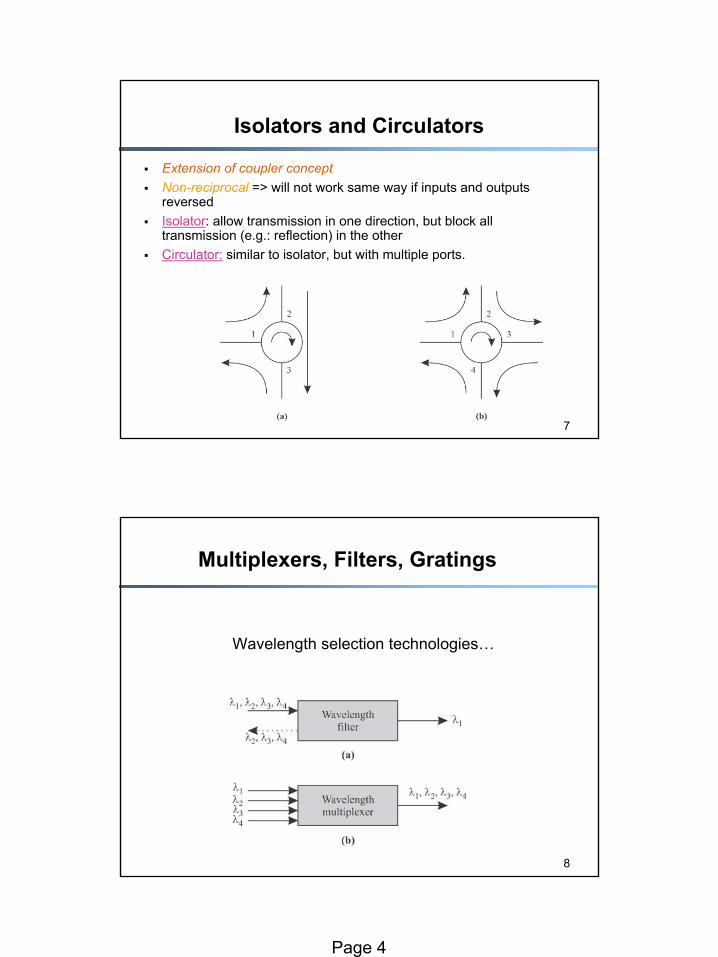
Extension of coupler conceptNon-reciprocal => will not work same way if inputs and outputs reversedIsolator: allow transmission in one direction, but block all transmission (e.g.: reflection) in the otherCirculator: similar to isolator, but with multiple ports.
8
Multiplexers, Filters, Gratings
Wavelength selection technologies…
Page 5
9
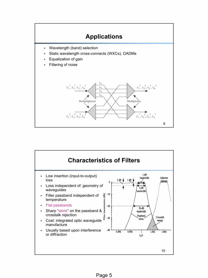
ApplicationsWavelength (band) selectionStatic wavelength cross-connects (WXCs), OADMsEqualization of gainFiltering of noise
10
Low insertion (input-to-output) lossLoss independent of: geometry of waveguidesFilter passband independent of temperatureFlat passbandsSharp “skirts” on the passband & crosstalk rejectionCost: integrated optic waveguide manufactureUsually based upon interference or diffraction
Characteristics of Filters
Page 6
11
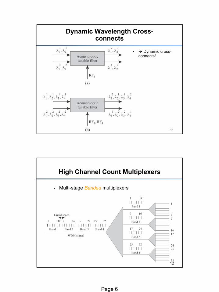
Dynamic Wavelength Cross-connects
Dynamic cross-connects!
12
High Channel Count Multiplexers
Multi-stage Banded multiplexers
Page 7
13
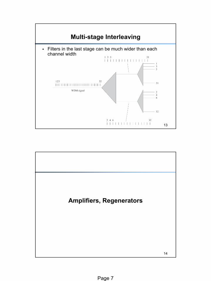
Multi-stage Interleaving
Filters in the last stage can be much wider than each channel width
14
Amplifiers, Regenerators
Page 8
15
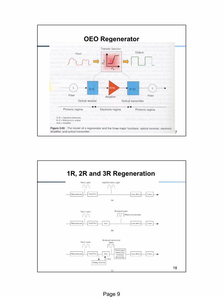
Amplification
16
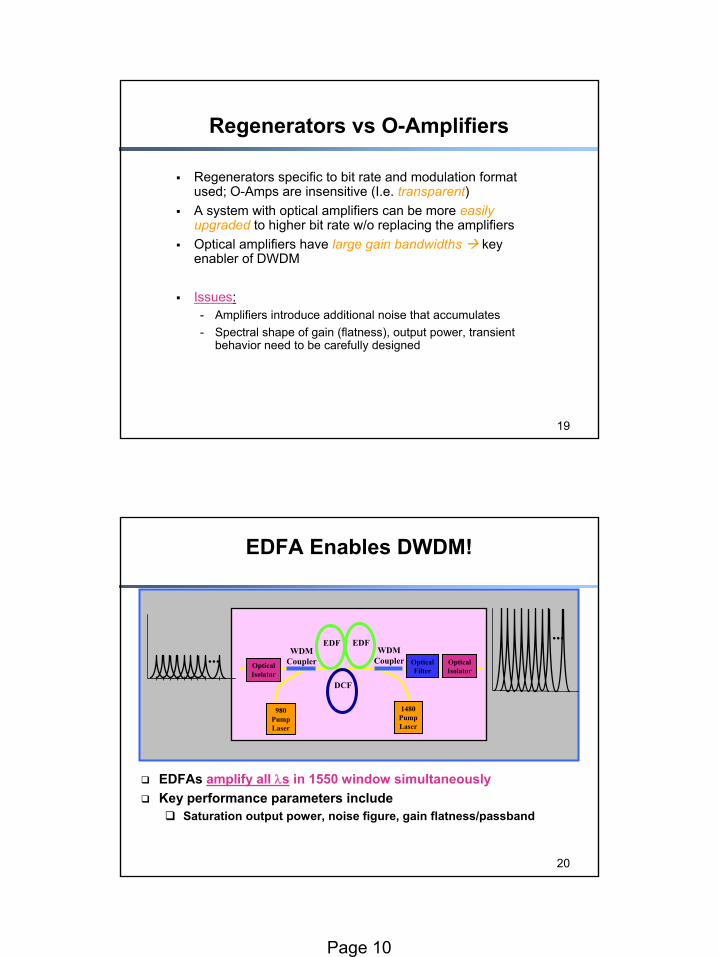
Optical Amplifiers vs Regenerators
40-80 km
Terminal
Regenerator - 3R (Reamplify, Reshape and Retime)
Terminal
120 km
TerminalTerminal
EDFA - 1R (Reamplify)
Terminal
EDFA amplifies all λs
Terminal
Terminal
Terminal
Terminal
Terminal
Page 9
17
OEO Regenerator
18
1R, 2R and 3R Regeneration
Page 10
19
Regenerators vs O-Amplifiers
Regenerators specific to bit rate and modulation format used; O-Amps are insensitive (I.e. transparent)A system with optical amplifiers can be more easily upgraded to higher bit rate w/o replacing the amplifiersOptical amplifiers have large gain bandwidths key enabler of DWDM
Issues:- Amplifiers introduce additional noise that accumulates- Spectral shape of gain (flatness), output power, transient
behavior need to be carefully designed
20
EDFA Enables DWDM!
EDFAs amplify all λs in 1550 window simultaneouslyKey performance parameters include
Saturation output power, noise figure, gain flatness/passband
......
980PumpLaser
WDMCoupler
WDMCoupler
EDF
DCF
OpticalIsolator
1480PumpLaser
OpticalFilter
OpticalIsolator
EDF
Page 11
21
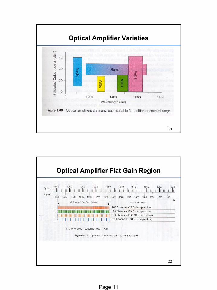
Optical Amplifier Varieties
22
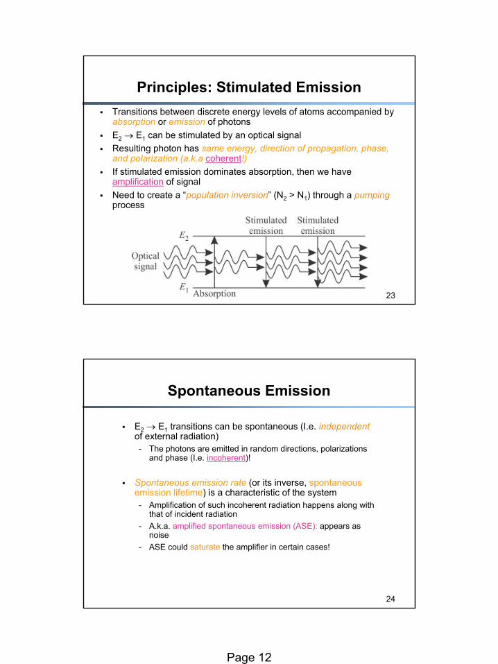
Optical Amplifier Flat Gain Region
Page 12
23
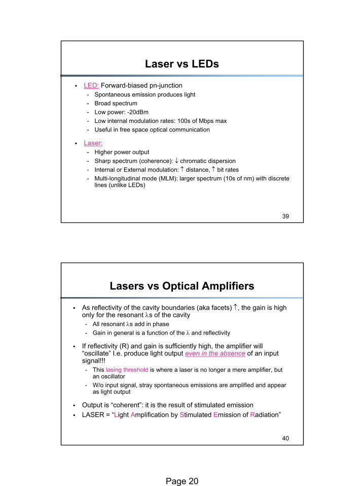
Principles: Stimulated EmissionTransitions between discrete energy levels of atoms accompanied by absorption or emission of photonsE2 → E1 can be stimulated by an optical signalResulting photon has same energy, direction of propagation, phase, and polarization (a.k.a coherent!)If stimulated emission dominates absorption, then we have amplification of signalNeed to create a “population inversion” (N2 > N1) through a pumpingprocess
24
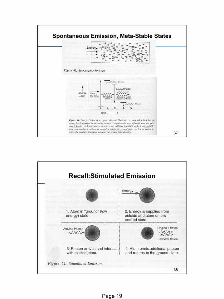
Spontaneous Emission
E2 → E1 transitions can be spontaneous (I.e. independentof external radiation)- The photons are emitted in random directions, polarizations
and phase (I.e. incoherent)!
Spontaneous emission rate (or its inverse, spontaneous emission lifetime) is a characteristic of the system- Amplification of such incoherent radiation happens along with
that of incident radiation- A.k.a. amplified spontaneous emission (ASE): appears as
noise- ASE could saturate the amplifier in certain cases!
Page 13
25
Optical Amplification: mechanics
26
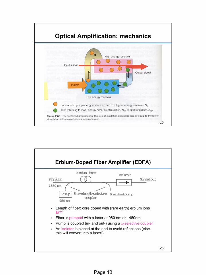
Erbium-Doped Fiber Amplifier (EDFA)
Length of fiber: core doped with (rare earth) erbium ions Er3+
Fiber is pumped with a laser at 980 nm or 1480nm. Pump is coupled (in- and out-) using a λ-selective couplerAn isolator is placed at the end to avoid reflections (else this will convert into a laser!)
Page 14
27
EDFA success factors
1. Availability of compact and reliable high-power semiconductor pump lasers2. EDFA is an all-fiber device polarization-independent & easy to couple light in/out3. Simplicity of device4. No crosstalk introduced while amplifying!
28
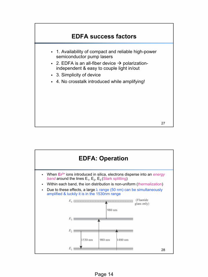
EDFA: Operation
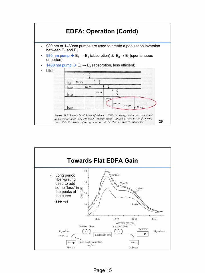
When Er3+ ions introduced in silica, electrons disperse into an energy band around the lines E1, E2, E3 (Stark splitting)Within each band, the ion distribution is non-uniform (thermalization)Due to these effects, a large λ range (50 nm) can be simultaneously amplified & luckily it is in the 1530nm range
Page 15
29
EDFA: Operation (Contd)
980 nm or 1480nm pumps are used to create a population inversionbetween E2 and E1
980 nm pump E1 → E3 (absorption) & E3 → E2 (spontaneous emission) 1480 nm pump E1 → E2 (absorption, less efficient)Lifetime in E3 is 1µs, whereas in E2 it is 10ms
30
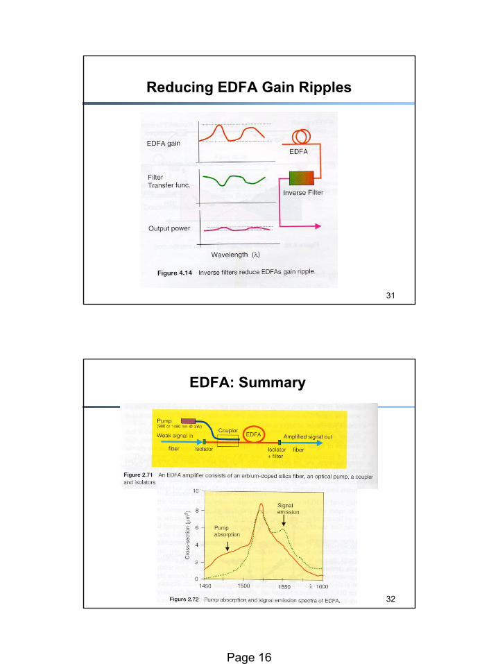
Towards Flat EDFA Gain
Long period fiber-grating used to add some “loss” in the peaks of the curve (see →)
Page 16
31
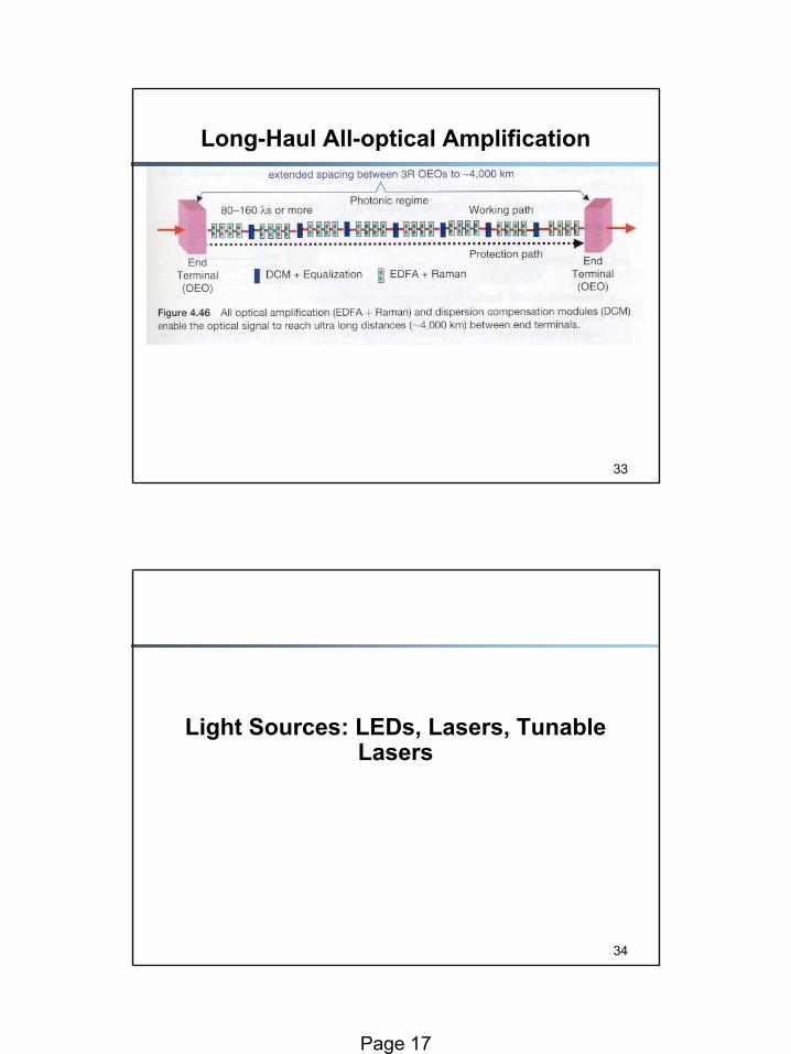
Reducing EDFA Gain Ripples
32
EDFA: Summary
Page 17
33
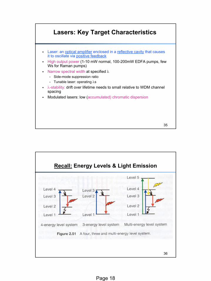
Long-Haul All-optical Amplification
34
Light Sources: LEDs, Lasers, Tunable Lasers
Page 18
35
Lasers: Key Target Characteristics
Laser: an optical amplifier enclosed in a reflective cavity that causes it to oscillate via positive feedbackHigh output power (1-10 mW normal, 100-200mW EDFA pumps, few Ws for Raman pumps)Narrow spectral width at specified λ- Side-mode suppression ratio- Tunable laser: operating λsλ-stability: drift over lifetime needs to small relative to WDM channel spacingModulated lasers: low (accumulated) chromatic dispersion
36
Recall: Energy Levels & Light Emission
Page 19
37
Spontaneous Emission, Meta-Stable States
38
Recall:Stimulated Emission
Page 20
39
Laser vs LEDs
LED: Forward-biased pn-junction - Spontaneous emission produces light- Broad spectrum- Low power: -20dBm- Low internal modulation rates: 100s of Mbps max- Useful in free space optical communication
Laser:- Higher power output- Sharp spectrum (coherence): ↓ chromatic dispersion- Internal or External modulation: ↑ distance, ↑ bit rates- Multi-longitudinal mode (MLM): larger spectrum (10s of nm) with discrete
lines (unlike LEDs)
40
Lasers vs Optical Amplifiers
As reflectivity of the cavity boundaries (aka facets) ↑, the gain is high only for the resonant λs of the cavity - All resonant λs add in phase- Gain in general is a function of the λ and reflectivity
If reflectivity (R) and gain is sufficiently high, the amplifier will “oscillate” I.e. produce light output even in the absence of an input signal!!!- This lasing threshold is where a laser is no longer a mere amplifier, but
an oscillator- W/o input signal, stray spontaneous emissions are amplified and appear
as light output
Output is “coherent”: it is the result of stimulated emissionLASER = “Light Amplification by Stimulated Emission of Radiation”
Page 21
41
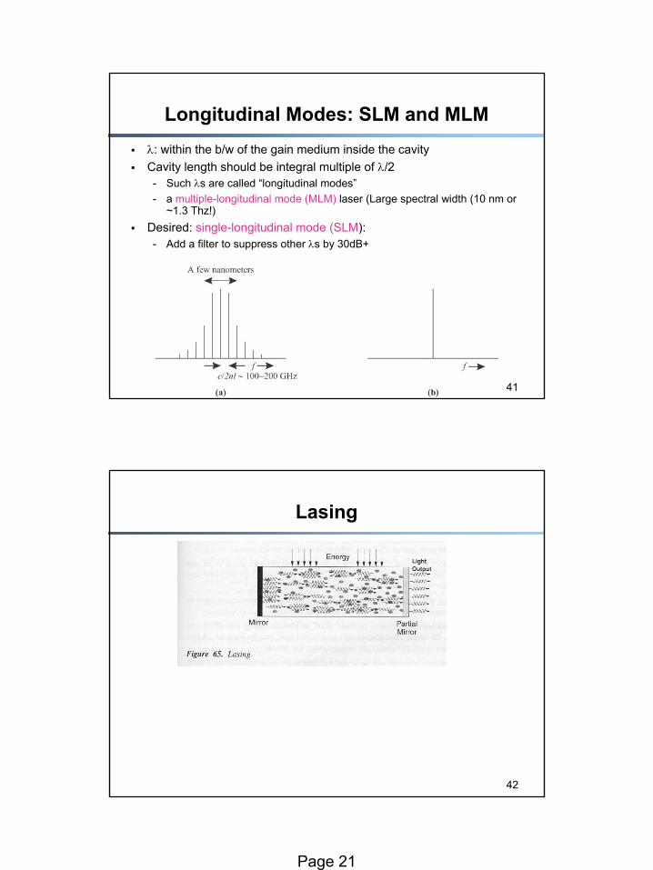
Longitudinal Modes: SLM and MLMλ: within the b/w of the gain medium inside the cavity Cavity length should be integral multiple of λ/2- Such λs are called “longitudinal modes”- a multiple-longitudinal mode (MLM) laser (Large spectral width (10 nm or
~1.3 Thz!)Desired: single-longitudinal mode (SLM): - Add a filter to suppress other λs by 30dB+
42
Lasing
Page 22
43
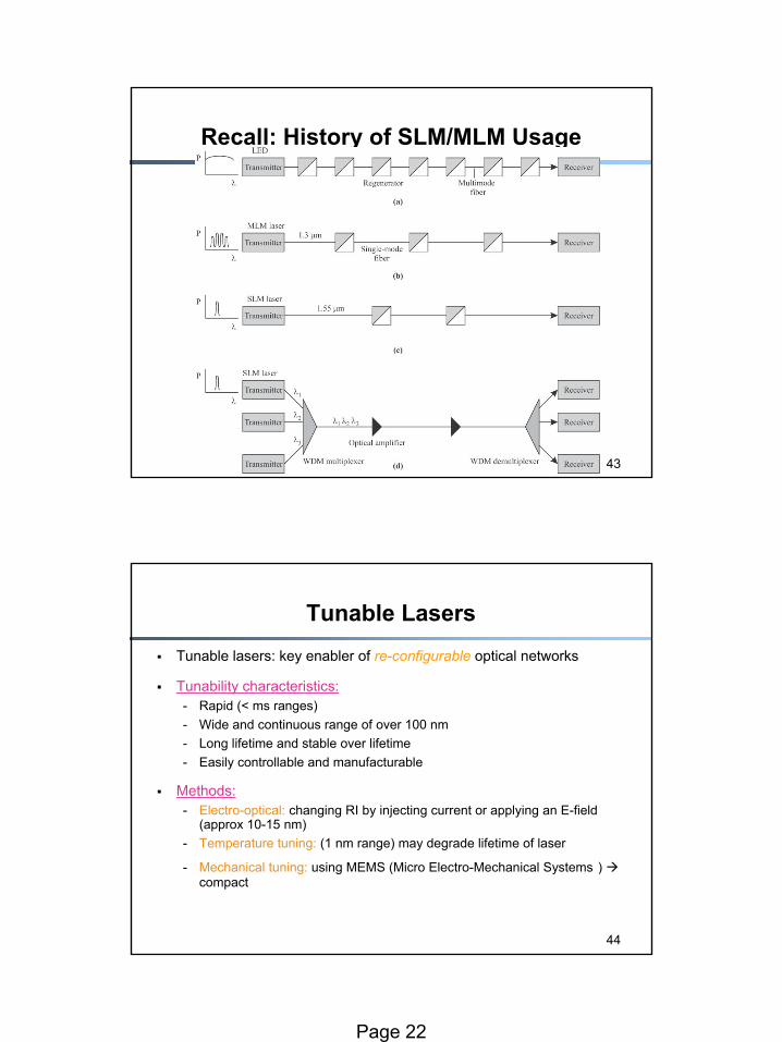
Recall: History of SLM/MLM Usage
44
Tunable LasersTunable lasers: key enabler of re-configurable optical networks
Tunability characteristics:- Rapid (< ms ranges)- Wide and continuous range of over 100 nm- Long lifetime and stable over lifetime- Easily controllable and manufacturable
Methods:- Electro-optical: changing RI by injecting current or applying an E-field
(approx 10-15 nm)- Temperature tuning: (1 nm range) may degrade lifetime of laser
- Mechanical tuning: using MEMS (Micro Electro-Mechanical Systems ) compact

Page 23
45
Photodetectors
46
Optical Receivers: Basic Ideas
Page 24
47
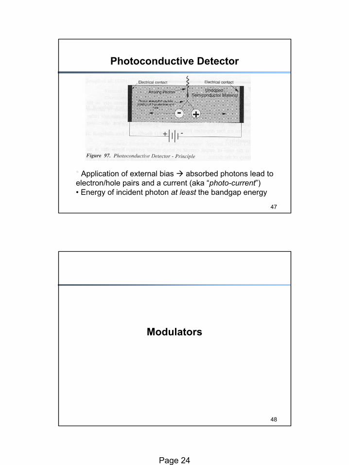
Photoconductive Detector
* Application of external bias absorbed photons lead to electron/hole pairs and a current (aka “photo-current”)• Energy of incident photon at least the bandgap energy
48
Modulators
Page 25
49
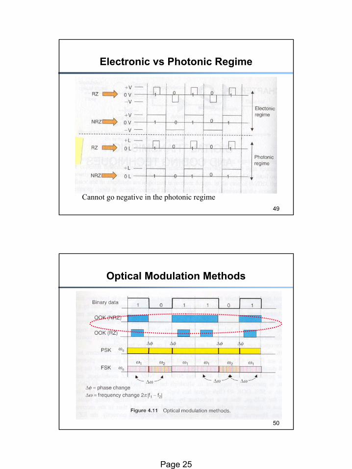
Electronic vs Photonic Regime
Cannot go negative in the photonic regime
50
Optical Modulation Methods
Page 26
51
Issues in Optical Modulation
On-Off keying (OOK) is the simplestDirect modulation vs External modulation- Extinction ratio: ratio of output power for bit=1 to output power for bit=0- Some lasers cannot be directly modulated- Direct modulation adds “chirp,” I.e., time variation of frequency within the
pulse!• Chirped pulses are more susceptible to chromatic dispersion• Combat chirp by increasing the power of bit=0, so that lasing
threshold is not lost• Reduction of extinction ratio (down to 7dB)
Solution: external modulation for higher speeds, longer distance/dispersion-limited regimes
52
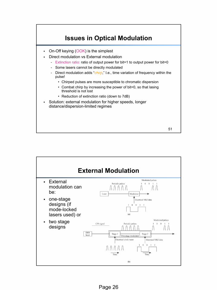
External ModulationExternal modulation can be:one-stage designs (if mode-locked lasers used) ortwo stage designs
Page 27
53
Switches
54
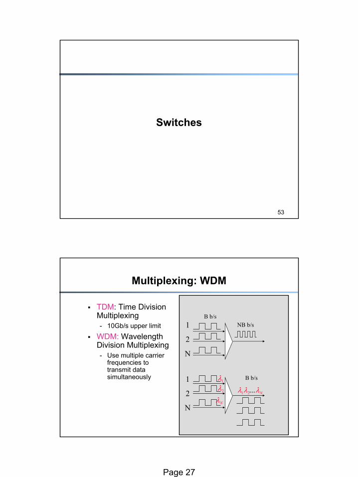
Multiplexing: WDM
TDM: Time Division Multiplexing- 10Gb/s upper limit
WDM: Wavelength Division Multiplexing- Use multiple carrier
frequencies to transmit data simultaneously
1λ2λ
Nλ1λ 2λ Nλ...
B b/sNB b/s1
2
N
1
2
N
B b/s
Page 28
55
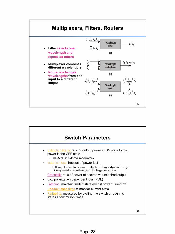
Filter selects one wavelength and rejects all others
Multiplexer combines different wavelengths Router exchanges wavelengths from one input to a different output
Multiplexers, Filters, Routers
56
Switch Parameters
Extinction Ratio: ratio of output power in ON state to the power in the OFF state- 10-25 dB in external modulators
Insertion loss: fraction of power lost- Different losses to different outputs larger dynamic range
may need to equalize (esp. for large switches)Crosstalk: ratio of power at desired vs undesired outputLow polarization dependent loss (PDL)Latching: maintain switch state even if power turned offReadout capability: to monitor current stateReliability: measured by cycling the switch through its states a few million times
Page 29
57
Switch Considerations
Number of switch elements: complexity of switchLoss uniformity: different losses to different outputs (esp for large switches)Number of crossovers: waveguide crossovers introduce power loss and crosstalk (not a problem for free-space-switches)Blocking characteristics: any unused input port can be connected to any unused output port?- Wide-sense non-blocking: without requiring any existing connection to be
re-routed make sure future connections will not block- Strict-sense non-blocking: regardless of previous connections- Re-arrangeably non-blocking: connections may be re-routed to make
them non-blocking
58
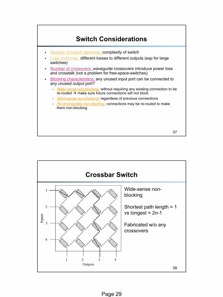
Crossbar Switch
Wide-sense non-blocking
Shortest path length = 1 vs longest = 2n-1
Fabricated w/o any crossovers
Page 30
59
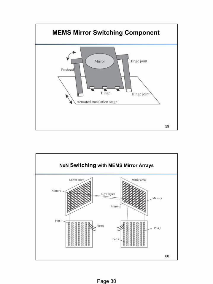
MEMS Mirror Switching Component
60
NxN Switching with MEMS Mirror Arrays
Page 31
61
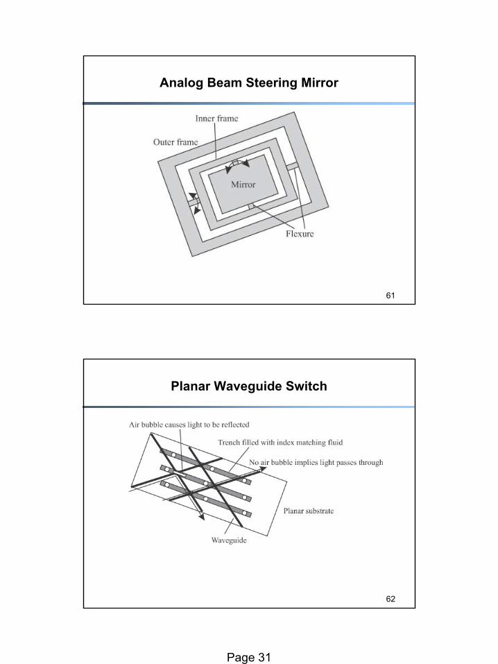
Analog Beam Steering Mirror
62
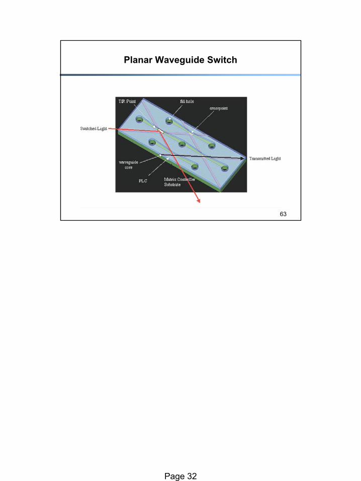
Planar Waveguide Switch
Page 32
63
Planar Waveguide Switch