Optical grooming switch with regenerative functionality...
13
Optical grooming switch with regenerative functionality for transparent interconnection of networks P. Vorreau 1 *, S. Sygletos 2 , F. Parmigiani 3 , D. Hillerkuss 1 , R. Bonk 1 , P. Petropoulos 3 , D. J. Richardson 3 , G. Zarris 4 , D. Simeonidou 4 , D. Klonidis 5 , I. Tomkos 5 , R. Weerasuriya 2 , S. Ibrahim 2 , A. D. Ellis 2 , D. Cotter 2 , R. Morais 6 , P. Monteiro 6 , S. Ben Ezra 7 , S. Tsadka 7 , W. Freude 1 , and J. Leuthold 1 1 Institute of Photonics and Quantum Electronics, University of Karlsruhe, Karlsruhe Institute of Technology, Kaiserstr. 12, 76131 Karlsruhe, Germany 2 Photonic Systems Group, Department of Physics, University College Cork, Ireland 3 Optoelectronics Research Centre, University of Southampton, Highfield, Southampton, SO17 1BJ, United Kingdom 4 School of Computer Science and Electronic Engineering, University of Essex, Wivenhoe Park, Colchester, CO4 3SQ, United Kingdom 5 Athens Information Technology (AIT), P.O. Box 68, Markopoulo Ave., GR - 19002 Peania, Athens, Greece 6 Nokia Siemens Networks Portugal S.A., Rua Irmãos Siemens 1, 2720-093 – Amadora 7 Finisar Israel, 3 Golda Meir St., Lev Hakongresim, Nitzan Building, Nes-Ziona Science Industrial Park, Nes Ziona 74140, Israel *[email protected] Abstract: We demonstrate a regenerative optical grooming switch for buffer-less interconnection of metro/access and metro/core ring networks with switching functionality in time, space and wavelength domain. Key functionalities of the router are the traffic aggregation with time-slot interchanging (TSI) functionality, the WDM-to-ODTM multiplexing and the OTDM-to-WDM demultiplexing of high-speed channel into lower bit- rate tributaries as well as multi-wavelength all-optical 2R regeneration of several higher-speed signals. BER and Q-factor measurements of different switching scenarios show excellent performance with no error floor and Q- factors above 21 dB. ©2009 Optical Society of America OCIS codes: (060.1155) All-optical networks; (060.2330) Fiber optics communications; (060.6718) Switching, circuit; (060.4230) Multiplexing. References and links 1. A. M. Saleh, and J. M. Simmons, “Evolution toward the next-generation core optical network,” J. Lightwave Technol. 24(9), 3303–3321 (2006). 2. A. Gladisch, R.-P. Braun, D. Breuer, A. Ehrhardt, H.-M. Foisel, M. Jaeger, R. Leppla, M. Schneiders, S. Vorbeck, W. Weiershausen, and F.-J. Westphal, “Evolution of Terrestrial Optical System and Core Network Architecture,” in Proc. IEEE 94, 869–891 (2006). 3. S. Sygletos, I. Tomkos, and J. Leuthold, “Technological challenges on the road toward transparent networking,” J. Opt. Netw. 7(4), 321–350 (2008). 4. J. Livas, “Optical Transmission Evolution: From Digital to Analog to? Network Tradeoffs Between Optical Transparency and Reduced Regeneration Cost,” J. Lightwave Technol. 23(1), 219–224 (2005). 5. O. Leclerc, “Towards Transparent Optical Networks: still some challenges ahead,” in Proceedings 18th Annual Meeting of the IEEE Lasers and Electro-Optics Society, paper TuCC3 (invited), 418–419 (2005). 6. L. Berthelon, C. Mathieu, D. Domin, J.-P. Fauro, R. Laalaoua, F. Pain, and M. Garnot, “Implementation of All- Optical Networks,” in Proceedings ECOC 2002, vol. 1, paper 1.4.1, (2002). 7. A. Morea, and J. Poirrier, “A Critical Analysis of the Possible Cost Savings of Translucent Networks,” in Proceedings of 5th international Workshop on Design of Reliable Communication Networks, 311–317, (2005). 8. D. T. Neilson, C. R. Doerr, D. M. Marom, R. Ryf, and M. P. Earnshaw, “Wavelength Selective Switching for Optical Bandwidth Management,” Bell Labs Technical J. 11(2), 105–128 (2006). 9. R. Ryf, J. Kim, J. P. Hickey, A. Gnauck, D. Carr, F. Pardo, C. Bolle, R. Frahm, N. Basavanhally, C. Yoh, D. Ramsey, R. Boie, R. George, J. Kraus, C. Lichtenwalner, R. Papazian, J. Gates, H. R. Shea, A. Gasparyan, V. Muratov, J. E. Griffith, J. A. Prybyla, S. Goyal, C. D. White, M. T. Lin, R. Ruel, C. Nijander, S. Arney, D. T. Nellson, D. J. Bishop, P. Kolodner, S. Pau, C. Nuzman, A. Weis, B. Kumar, D. Lieuwen, V. Aksyuk, D. S. Greywall, T. C. Lee, H. T. Soh, W. M. Mansfield, S. Jin, W. Y. Lai, H. A. Huggins, D. L. Barr, R. A. Cirelli, G. #110279 - $15.00 USD Received 20 Apr 2009; revised 8 Jun 2009; accepted 22 Jul 2009; published 12 Aug 2009 (C) 2009 OSA 17 August 2009 / Vol. 17, No. 17 / OPTICS EXPRESS 15173
Transcript of Optical grooming switch with regenerative functionality...

Optical grooming switch with regenerative functionality for transparent interconnection of
networks
P. Vorreau1*, S. Sygletos
2, F. Parmigiani
3, D. Hillerkuss
1, R. Bonk
1, P. Petropoulos
3, D.
J. Richardson3, G. Zarris
4, D. Simeonidou
4, D. Klonidis
5, I. Tomkos
5, R. Weerasuriya
2,
S. Ibrahim2, A. D. Ellis
2, D. Cotter
2, R. Morais
6, P. Monteiro
6, S. Ben Ezra
7, S. Tsadka
7,
W. Freude1, and J. Leuthold
1
1Institute of Photonics and Quantum Electronics, University of Karlsruhe, Karlsruhe Institute of Technology, Kaiserstr. 12, 76131 Karlsruhe, Germany
2Photonic Systems Group, Department of Physics, University College Cork, Ireland 3Optoelectronics Research Centre, University of Southampton, Highfield, Southampton, SO17 1BJ, United Kingdom
4School of Computer Science and Electronic Engineering, University of Essex, Wivenhoe Park, Colchester, CO4 3SQ, United Kingdom
5Athens Information Technology (AIT), P.O. Box 68, Markopoulo Ave., GR - 19002 Peania, Athens, Greece 6Nokia Siemens Networks Portugal S.A., Rua Irmãos Siemens 1, 2720-093 – Amadora
7 Finisar Israel, 3 Golda Meir St., Lev Hakongresim, Nitzan Building, Nes-Ziona Science Industrial Park, Nes Ziona 74140, Israel
Abstract: We demonstrate a regenerative optical grooming switch for buffer-less interconnection of metro/access and metro/core ring networks with switching functionality in time, space and wavelength domain. Key functionalities of the router are the traffic aggregation with time-slot interchanging (TSI) functionality, the WDM-to-ODTM multiplexing and the OTDM-to-WDM demultiplexing of high-speed channel into lower bit-rate tributaries as well as multi-wavelength all-optical 2R regeneration of several higher-speed signals. BER and Q-factor measurements of different switching scenarios show excellent performance with no error floor and Q-factors above 21 dB.
©2009 Optical Society of America
OCIS codes: (060.1155) All-optical networks; (060.2330) Fiber optics communications; (060.6718) Switching, circuit; (060.4230) Multiplexing.
References and links
1. A. M. Saleh, and J. M. Simmons, “Evolution toward the next-generation core optical network,” J. Lightwave Technol. 24(9), 3303–3321 (2006).
2. A. Gladisch, R.-P. Braun, D. Breuer, A. Ehrhardt, H.-M. Foisel, M. Jaeger, R. Leppla, M. Schneiders, S. Vorbeck, W. Weiershausen, and F.-J. Westphal, “Evolution of Terrestrial Optical System and Core Network Architecture,” in Proc. IEEE 94, 869–891 (2006).
3. S. Sygletos, I. Tomkos, and J. Leuthold, “Technological challenges on the road toward transparent networking,” J. Opt. Netw. 7(4), 321–350 (2008).
4. J. Livas, “Optical Transmission Evolution: From Digital to Analog to? Network Tradeoffs Between Optical Transparency and Reduced Regeneration Cost,” J. Lightwave Technol. 23(1), 219–224 (2005).
5. O. Leclerc, “Towards Transparent Optical Networks: still some challenges ahead,” in Proceedings 18th Annual Meeting of the IEEE Lasers and Electro-Optics Society, paper TuCC3 (invited), 418–419 (2005).
6. L. Berthelon, C. Mathieu, D. Domin, J.-P. Fauro, R. Laalaoua, F. Pain, and M. Garnot, “Implementation of All-Optical Networks,” in Proceedings ECOC 2002, vol. 1, paper 1.4.1, (2002).
7. A. Morea, and J. Poirrier, “A Critical Analysis of the Possible Cost Savings of Translucent Networks,” in Proceedings of 5th international Workshop on Design of Reliable Communication Networks, 311–317, (2005).
8. D. T. Neilson, C. R. Doerr, D. M. Marom, R. Ryf, and M. P. Earnshaw, “Wavelength Selective Switching for Optical Bandwidth Management,” Bell Labs Technical J. 11(2), 105–128 (2006).
9. R. Ryf, J. Kim, J. P. Hickey, A. Gnauck, D. Carr, F. Pardo, C. Bolle, R. Frahm, N. Basavanhally, C. Yoh, D. Ramsey, R. Boie, R. George, J. Kraus, C. Lichtenwalner, R. Papazian, J. Gates, H. R. Shea, A. Gasparyan, V. Muratov, J. E. Griffith, J. A. Prybyla, S. Goyal, C. D. White, M. T. Lin, R. Ruel, C. Nijander, S. Arney, D. T. Nellson, D. J. Bishop, P. Kolodner, S. Pau, C. Nuzman, A. Weis, B. Kumar, D. Lieuwen, V. Aksyuk, D. S. Greywall, T. C. Lee, H. T. Soh, W. M. Mansfield, S. Jin, W. Y. Lai, H. A. Huggins, D. L. Barr, R. A. Cirelli, G.
#110279 - $15.00 USD Received 20 Apr 2009; revised 8 Jun 2009; accepted 22 Jul 2009; published 12 Aug 2009
(C) 2009 OSA 17 August 2009 / Vol. 17, No. 17 / OPTICS EXPRESS 15173
R. Bogart, K. Teffeau, R. Vella, H. Mavoori, A. Ramirez, N. A. Ciampa, F. P. Klemens, M. D. Morris, T. Boone, J. Q. Liu, J. M. Rosamilia, and C. R. Giles, “1296-port MEMS Transparent Optical Crossconnect with 2.07Petabit/s Switch Capacity,” in Proceedings Optical Fiber Communications Conference 2001, paper PD28–1, (2001).
10. D. J. Bishop, C. R. Giles, and G. P. Austin, “The Lucent LambdaRouter: MEMS Technology of the Future Here Today,” IEEE Commun. Mag. 40(3), 75–79 (2002).
11. P. Vorreau, D. Hillerkuss, F. Parmigiani, S. Sygletos, R. Bonk, P. Petropoulos, D. Richardson, G. Zarris, D. Simeonidou, D. Klonidis, I. Tomkos, R. Weerasyriya, S. Ibrahim, A. Ellis, R. Morais, P. Monteiro, S. Ben Ezra, S. Tsadka, W. Freude, and J. Leuthold, “2R/3R Optical Grooming Switch with Time-Slot Interchange,” in Proceedings ECOC 2008, PDP Th.3.F.4, (2008).
12. G. Zarris, F. Parmigiani, E. Hugues-Salas, R. Weerasuriya, D. Hillerkuss, N. Amaya, and M. Gonzalez, Spyropoulou, P. Vorreau, R. Morais, S.K. Ibrahim, D. Klonidis, P. Petropoulos, A. D. Ellis, P. Monteiro, A. Tzanakaki, D. Richardson, I. Tomkos, R. Bonk, W. Freude, J. Leuthold, and D. Simeonidou, “Field Trial of WDM-OTDM transmultiplexing employing photonic switch fabric-based buffer-less bit-interleaved data grooming and all-optical regeneration,” in Proceedings OFC 2009, PDPC10, (2009).
13. B. Mukherjee, C. Ou, H. Zhu, K. Zhu, N. Singhal, and S. Yao, “Traffic Grooming in Mesh Optical Networks,” in Proceedings of Optical Fiber Communications Conference, vol. 2, paper ThG1, Feb. 23–27, (2004).
14. D. Cotter, and A. D. Ellis, “Asynchronous digital optical regeneration and networks,” J. Lightwave Technol. 16(12), 2068–2080 (1998).
15. G. Zarris, P. Vorreau, D. Hillerkuss, S. K. Ibrahim, R. Weerasuriya, A. D. Ellis, J. Leuthold, and D. Simeonidou, “WDM-to-OTDM Traffic Grooming by means of Asynchronous Retiming,” in Proceedings OFC 2009, paper OThJ6, (2009).
16. F. Parmigiani, P. Vorreau, L. Provost, K. Mukasa, P. Petropoulos, D. J. Richardson, W. Freude, and J. Leuthold, “2R Regeneration of two 130 Gbit/s Channels within a Single Fiber,” in Proceedings OFC 2009, paper JThA56, (2009).
17. R. Morais, R. Meleiro, P. Monteiro, and P. Marques, “OTDM-to-WDM Conversion based on Wavelength Conversion and Time Gating in a Single Optical Gate,” in Proceedings OFC 2007, paper OTuD5, (2007).
18. P. V. Mamyshev, “All-optical data regeneration based on self-phase modulation effect,” in Proceedings ECOC 1998, pp. 475–476, (1998).
19. H. Sotobayashi, W. Chujo, and K.- Kitayama, “Photonic gateway: TDM-to-WDM-to-TDM conversion and reconversion at 40 Gbit/s (4 channels × 10 Gbit/s),” J. Opt. Soc. Am. B 19(11), 2810–2816 (2002).
20. P. Vorreau, F. Parmigiani, K. Mukasa, M. Ibsen, P. Ptropoulos, D. J. Richardson, A. Ellis, W. Freude, and J. Leuthold, “TDM-to-WDM Conversion from 130 Gbit/s to 3 × 43 Gbit/s Using XPM in a NOLM Switch,” in Proceedings ICTON 2008, paper Th.PD.2, (2008).
21. S. K. Ibrahim, R. Weerasuriya, D. Hillerkuss, G. Zarris, D. Simeonidou, J. Leuthold, D. Cotter, and A. Ellis, “Experimental demonstration of 42.6Gbit/S asynchronous digital optical regenerators,” in Proceedings ICTON 2008, paper We.C3.3, (2008).
22. P. Vorreau, Ch. Kouloumentas, L. Provost, I. Tomkos, W. Freude, and J. Leuthold, “Simultaneous Processing of 43 Gb/s WDM Channels by a Fiber-Based Dispersion-Managed 2R Regenerator,” in Proceedings ECOC 2008, paper Th.1.B.3, (2008).
23. D. V. Kuksenkov, S. Li, M. Sauer, and D. A. Nolan, “Nonlinear Fibre Devices Operating on Multiple WDM Channels,” in Proceedings ECOC 2005, paper Mo3.5.1, (2005).
24. L. Provost, F. Parmigiani, P. Petropoulos, and D. J. Richardson, “Investigation of Simultaneous 2R Regeneration of Two 40-Gb/s Channels in a Single Optical Fiber,” Photon. Technol. Lett. 20(4), 270–272 (2008).
25. L. Provost, F. Parmigiani, P. Petropoulos, D. J. Richardson, K. Mukasa, M. Takahashi, J. Hiroishi, and M. Tadakuma, “Investigation of Four-Wavelength Regenerator Using Polarization- and Direction-Multiplexing,” Photon. Technol. Lett. 20(20), 1676–1678 (2008).
26. F. Cisternino, R. Girardi, S. Romisch, R. Calvani, E. Riccardi, and P. Garino, “A novel approach to pre-scaled clock recovery in OTDM systems,” in Proc. ECOC 1998 1, 477–478 (1998).
27. C. Koos, P. Vorreau, T. Vallaitis, P. Dumon, W. Bogaerts, R. Baets, B. Esembeson, I. Biaggio, T. Michinobu, F. Diederich, W. Freude, and J. Leuthold, “All-optical high-speed signal processing with silicon-organic hybrid slot waveguides,” Nat. Photonics 3(4), 216–219 (2009).
1. Introduction
The enormous growth of IP traffic over the last years, which has been fueled by the proliferation of new integrated services and applications, i.e., high-speed data and video-on-demand, has dramatically increased the bandwidth and performance requirements in optical networks [1,2]. In the backbone network the introduction of the wavelength division multiplexing (WDM) technology is responding to this demand by the introduction of transparent high capacity networks over extended optical paths [3]. However, transparency at the network edges, i.e., from the backbone to the metro and access and vice-versa, is still an issue. The main reason is that metro and access networks are subject to specific traffic demands and performance requirements that are quite different from that of the backbone. Metro/access networks are particularly cost sensitive and have to cope with a more rapidly
#110279 - $15.00 USD Received 20 Apr 2009; revised 8 Jun 2009; accepted 22 Jul 2009; published 12 Aug 2009
(C) 2009 OSA 17 August 2009 / Vol. 17, No. 17 / OPTICS EXPRESS 15174

changing traffic profile. This requires fast connection provisioning as well as the ability for network scalability, modularity and reconfigurability. In addition, metro/access networks need to provide functionalities such as grooming and aggregation of the traffic to be able to connect a wide range of enterprise/private customers in the access with those in the backbone. So far, those critical switching and traffic grooming functionalities are supported by the synchronous digital hierarchy (SDH) or the synchronous optical network (SONET) standard. Although the SDH systems are well established and reliable solutions, they are costly due to the high energy consumption of the many optical-electrical-optical (O-E-O) conversions required [4,5]. While opaque switching solutions offer excellent grooming capabilities, typically they adopt architectures that scale poorly with port count and port-data rate. Furthermore, electronic circuit switching has proved to be very restrictive exhibiting cumbersome provisioning procedures. Network studies have shown that deploying alternatives to electronic grooming potentially will have the largest impact on reducing overall network cost [1]. Optical switching technologies, on the other hand, have the potential to overcome those issues. Compared to their electronic counterparts, optical switches are characterized by significantly lower power consumption and footprint, which leads to significant operational expenditures (OPEX) savings [6–8]. Furthermore, they can deal with significantly higher capacities (~1 Tbit/s) than normal IP routers [9,10]. Optical switches also offer larger indifference in terms of protocol, modulation format and bit rate as compared to their electronic counterparts. This enhances the upgradeability of the networking infrastructure to higher capacity requirements and new types of data traffic. While current optical cross connect-based solutions enable both switching and routing they cannot provide transparent mechanisms for time division multiplexing/demultiplexing, which are necessary for traffic grooming.
In this paper we have designed and implemented a novel switch architecture that offers a transparent interconnection of different metro networks i.e. between metro/access and metro/core at bit-rates of 40 Gbit/s and 130 Gbit/s, respectively [11]. The proposed switch integrates all the crucial functionalities that are currently provided by digital cross-connects (DXC), i.e. switching, traffic aggregation/grooming and direct regeneration in the optical layer. Our approach offers broadband access for every user and interoperability with existing infrastructures. Therefore, it can be a viable alternative to SONET/SDH accommodating the high processing and capacity requirements of the emerging services and applications in a cost effective way. We believe that our proposed solution has the potential to boost the progress in the metro networks and may match the technological leaps that have already been carried out at the backbone and access parts. And indeed, a field trial of the novel switch node recently demonstrated its feasibility [12].
This paper discusses the technology and system aspects of the proposed optical grooming switch and is organized as follows: In Section 2 a description of the switch node architecture is presented. Section 3 briefly introduces the underlying technologies offering the required optical functionalities. Section 4 shows experimental results for the full node assembly in a system testbed. Section 5 summarizes the paper.
2. Switch Node Description
2.1 Node Functionality
The switch node under discussion is operated here as an “edge node” that interfaces metro/core rings and metro/access rings, see Fig. 1(a). The node is designed to provide connectivity through optical wavelength switching and to accommodate the particular requirements of metro networks by offering traffic grooming and bit-rate adaptation. Furthermore, to guarantee the quality of the traffic in the metro/core ring, an all-optical multi-wavelength signal regenerator is added in the core ring. Finally, in this network scheme, coarse wavelength division multiplexing (CWDM) has been used. For simplicity of notation, in the following we will use metro ring and core ring instead of metro/access ring and metro/core ring, respectively.
#110279 - $15.00 USD Received 20 Apr 2009; revised 8 Jun 2009; accepted 22 Jul 2009; published 12 Aug 2009
(C) 2009 OSA 17 August 2009 / Vol. 17, No. 17 / OPTICS EXPRESS 15175

Fig. 1. Network scenario and switch node. (a) Two metro/access rings are interconnected to a metro/core ring via the grooming switch. Each ring carries a multiple of WDM channels, either at 43 Gbit/s or 130 Gbit/s per wavelength. (b) Grooming switch block diagram. Traffic from the metro/access rings is switched by the space switch either to the other access rings, or via the add path to the metro/core ring. Conversely, an OTDM channel from the metro/core ring can be dropped, and any of the three OTDM tributaries may be mapped to any of the metro/access rings or back to the core ring. The signals in this plot show one possible switching scenario: Three OTDM tributaries at λcore1 are dropped to the OTDM-to-WDM converter. Two of its outputs (carrying time-slots TS1 and TS3) are switched to the WDM-to-OTDM converter, slot-interchanged and looped back to the core ring. Channel λacc1 from metro ring 1 is added and mapped to time-slot TS2. In addition, the dropped time-slot TS2 is mapped to λacc2 on metro ring 2.
A schematic illustration of the switch node is depicted in Fig. 1(b). Irrespectively of any specific network scenario, the switch node can be classified as an optical multi-hop partial-grooming optical cross-connect (OXC) [13], which consists of three wavelength switch fabric in the form of reconfigurable optical add-drop multiplexers (ROADM) and a grooming fabric in the center of the switch. The ROADM allow for adding and dropping of traffic from the access or the core network onto the grooming fabric. The grooming fabric performs TDM and WDM multiplexing, demultiplexing, and switching between low-speed (43 Gbit/s) and high-speed (130 Gbit/s) connections.
In detail, the grooming switch works as follows, Fig. 1(b): Traffic from any of the metro rings is switched by means of an optical space switch (micro-electro-mechanical system (MEMS)) to any of the metro rings, or via the add path to the core ring. When the traffic is switched to the core add path, a WDM-to-OTDM unit retimes the incoming asynchronous
#110279 - $15.00 USD Received 20 Apr 2009; revised 8 Jun 2009; accepted 22 Jul 2009; published 12 Aug 2009
(C) 2009 OSA 17 August 2009 / Vol. 17, No. 17 / OPTICS EXPRESS 15176
data signals with reference to a local clock. The retimed signals are converted to short high-repetition rate pulses at a new wavelength in conformity to the OTDM channel requirements. The WDM-to-OTDM conversion operation is based on the asynchronous digital optical regenerator (ADORE), which has been described in more detail in [14]. The assignments and order of the time-slots of the WDM tributaries within the output OTDM can be chosen freely by the space switch. Conversely, a core OTDM channel may be dropped via the ROADM and any of the three OTDM tributaries can be mapped onto any of the access rings or back onto the core ring. Therefore, the time-slots can be interchanged [15]. To guarantee the quality of the 130 Gbit/s traffic in the core ring all-optical multi-wavelength regenerators are added [16].
2.2 Subsystem Functionality
In detail, the key functionalities of the switch node can be summarized as:
• Wavelength selective optical switching, which is achieved through a reconfigurable optical add/drop multiplexer (ROADM).
• Traffic grooming (equivalent to traffic aggregation in combination with switching), which is achieved by utilizing WDM-to-OTDM conversions (transmultiplexing) and vice versa.
• Time-slot interchange (TSI), where traffic in the core ring can be switched from one wavelength/time-slot to any other wavelength/time-slot at the node. This includes the possibility to interchange the time-slots of one wavelength by dropping and looping-back that wavelength through the add path. TSI is achieved by utilizing WDM-to-OTDM conversions and vice versa in combination with the space switch.
• Optical multi-wavelength 2R regeneration of the signals that leave the node via the core ring.
The wavelength switching functionality that is enabled by the space switch/ROADMs allows dynamic wavelength selection and thus switching of the individual channels to any fiber ring. This dynamic allocation of the optical bandwidth and the on-demand establishment of connections will enable the supply of broadband services to end-users.
The traffic aggregation and grooming that is enabled by the WDM-to-OTDM and OTDM-to-WDM converters also plays a critical role in reducing the network operational expenditure (OPEX). Future networks must support a variety of traffic protocols. Considering that this inhomogeneous traffic at lower data rates needs to be aggregated at the edge between metro and core segments into high date rate channels, it is important that the offered traffic aggregation and grooming mechanisms are also transparent to traffic protocols. This will further assist in simplifying the network architecture and eliminating a large number of costly opto-electronic conversions. In the proposed node such grooming functionality is enabled by multiplexing several lower data rate 43 Gbit/s channels to a high date rate 130 Gbit/s signals. This is achieved through optical WDM-to-OTDM and OTDM-to-WDM converters. A detailed description of their operating principles is given in the following sections.
The quality of the 130 Gbit/s traffic in the core ring is guaranteed by an all-optical multi-wavelength regenerator. The multi-wavelength 2R regeneration (see Fig. 1(b)) is also very important in terms of cost-efficiency. It provides simultaneous regeneration of a WDM signal incorporating a number of individual wavelength channels. Therefore, it will eliminate the requirement of demultiplexing WDM signals into individual wavelength channels, and the use of a single regenerative device per wavelength followed by subsequent multiplexing. The multi-wavelength processing capability of our regenerator mirrors that of optical amplification, with the added benefit of restoration of the signal quality.
3. Subsystems Operation Principles and Characterization
The wavelength switching functionality provided by the proposed system is supported through the existing ROADM and space switch technologies. However, to enable traffic grooming/aggregation as well as multi-wavelength regeneration, novel all-optical subsystems need be developed and incorporated into the node. In this section a detailed description of the
#110279 - $15.00 USD Received 20 Apr 2009; revised 8 Jun 2009; accepted 22 Jul 2009; published 12 Aug 2009
(C) 2009 OSA 17 August 2009 / Vol. 17, No. 17 / OPTICS EXPRESS 15177

operating principle of the key grooming and regeneration subsystems is given, namely the TDM-to-WDM and WDM-to-TDM converters as well the 2R regenerator.
3.1 OTDM-to-WDM Converter
Fig. 2. Operation principle of the OTDM to WDM conversion. HP-EDFA – high-power EDFA; HNLF – highly-nonlinear fiber.
The operating principle of the OTDM-to-WDM conversion unit is illustrated in Fig. 2 [17]. Here a 130 Gbit/s OTDM signal is converted into three WDM tributaries running at 43 Gbit/s each. This is achieved through the following three stage process. In a first stage, the 130 Gbit/s OTDM signal is replicated into three different wavelengths by means of a multi-wavelength converter. The multi-wavelength conversion process is based on a technique proposed by Mamyshev [18]. Using a highly nonlinear Kerr medium, which in our case is highly nonlinear fiber (HNLF), the input OTDM signal experiences spectral broadening due to the self-phase modulation (SPM) effect. The three replicas of the signal are then obtained by performing simultaneous symmetrical filtering on the right and left sides of the broadened spectrum, plus the original signal. The second stage of the subsystem performs temporal alignment of the three tributaries so that their different time slots are superimposed. This is achieved by an array of optical delay lines (ODL). In the final step time gating of the three replicas takes place, which isolates every third pulse in its corresponding WDM channel. For this operation we used a commercially available electro-absorption modulator (EAM).
For performance evaluation we carried out bit error rate (BER) measurements. The OTDM input signal had a centre wavelength of 1555.5 nm and an average launch power into the HNLF of 25 dBm. The spectral widths (3-dB) of the signal at the in- and output of the HNLF were 2.2 nm and 11.9 nm, respectively. The BER curves in Fig. 3 show the BER of the back-to-back 130 Gbit/s OTDM signal (black squares) and the BER of the three demultiplexed signals (triangles). Error free operation can be seen. The maximum penalty on receiver
sensitivity (at BER = 10−9
) compared to the back-to-back signal is 2.2 dB. No crosstalk between wavelengths is observed. The authors attribute the developing error floor for longer wavelengths to the wavelength dependent performance of the EAM. The FWHM of the EAM switching window for 1550.9 nm, 1555.5 nm and 1560.6 nm is 4.8 ps (4.7 ps), 5.5 ps (4.8 ps) and 5.9 ps (5.1 ps) for TE (TM) polarization, respectively. The wider windows with increased variations for the longer wavelength lead to increased crosstalk from neighbouring TDM bit-slots. The subsystem performance can be further improved by choosing an EAM with its operating point adapted to the wavelength range. Note that while in principle this technique is not limited to 1-to-3 conversion [19], the actual implementation is limited to converting one input signal at a specific wavelength due to fixed filters. However, scalability is provided by adding individual converters for each core wavelength that needs to be dropped to the metro rings.
#110279 - $15.00 USD Received 20 Apr 2009; revised 8 Jun 2009; accepted 22 Jul 2009; published 12 Aug 2009
(C) 2009 OSA 17 August 2009 / Vol. 17, No. 17 / OPTICS EXPRESS 15178

Fig. 3. Receiver bit error rates of the three 43 Gbit/s outputs of the TDM-to-WDM subsystem and the 130 Gbit/s input signal to the subsystem demultiplexed with the same type of EAM used in the subsystem. A small maximal penalty of 2.2 dB compared to the back-to-back (B-to-B) signal is observed for the 1560.6 nm output signal.
We have also implemented an alternative scheme with wavelength interchangeability where tributaries are mapped onto clocks from tunable sources using a nonlinear optical loop mirror as the nonlinear switch [20]. While the later scheme is quite sensitive to input signal polarization, it offers the advantage of free selection of all three output wavelengths. However, the SPM-based technique demonstrated in this paper also presents several compelling advantages when comparing to other OTDM-to-WDM conversion schemes. It is a simple single pass technique and shows low dependence on the polarization of the input OTDM signal if the HNLF used is properly chosen. Furthermore, it doesn’t need extra laser sources.
3.2 WDM-to-OTDM Converter
The concept of WDM-to-OTDM is depicted in Fig. 4 for the case where three tributaries are multiplexed onto a single OTDM channel. Our technique is based on the dual-gate ADORE scheme [21], where the three low bit-rate tributaries are synchronized to the same local clock, pulse widths are shortened and mapped to the same wavelength in an ADORE each. In more detail the dual-gate ADORE works as follows. Optical clock pulses are generated from a mode-locked laser (MLL) driven by a local clock oscillator (see Fig. 4). These optical clock pulses are applied to the inputs of two gates, one of these inputs being delayed relative to the other by half of the bit period T/2. If there is a “1” bit within the 43 Gbit/s RZ signal streams, the two gates will be opened simultaneously. Typically, one of the MLL laser pulses will be better in synchronization with the gating window and thus exhibit higher power. By reversing the delays before and after the optical gates, both possible clock signal paths are of identical total length, so that the output signal will be synchronized to the local clock. Selecting the path with the higher signal power provides the full information of the input signal – yet retimed to the local optical clock and with the pulse width and wavelength of a core ring OTDM tributary. In our experiment, the selection of the path with the higher signal power is provided by a simple phase comparator circuit in combination with a 2 × 1 optical switch [21]. The same ADORE scheme is applied to each of the WDM input signals resulting in three synchronized OTDM tributaries at the same wavelength. The three OTDM tributaries are subsequently temporally aligned and combined to form the OTDM channel.
#110279 - $15.00 USD Received 20 Apr 2009; revised 8 Jun 2009; accepted 22 Jul 2009; published 12 Aug 2009
(C) 2009 OSA 17 August 2009 / Vol. 17, No. 17 / OPTICS EXPRESS 15179

Fig. 4. WDM-to-OTDM traffic grooming utilizing the asynchronous retiming concept. The incoming 43 Gbit/s signals are synchronized to a local oscillator, wavelength converted and the pulse width is shortened using three ADOREs. The output short pulse signals are temporally aligned and combined to form the 130 Gbit/s OTDM signal. Sync. – synchronization; WLC – wavelength conversion; MLL – mode-locked laser.
To show that error free WDM-to-OTDM multiplexing is possible independent of the respective clock phase of the WDM input signals we have performed an experiment as follows [15]. While keeping the relative time synchronization of two OTDM tributaries (TS2 and TS3) optimum we varied the input WDM signal synchronization of a third tributary (TS1) over a whole bit period while observing the BER performance of all three OTDM tributaries. Figure 5(a) shows the power penalty results on the three tributaries after demultiplexing using an EAM. TS1 was measured at both best (‘ADORE best’) and worst input data synchronization (‘ADORE worst’). The worst synchronization corresponds to the point just before or just after the dual-gate ADORE switches. Measurements on either side of the switching event were taken (‘ADORE worst 1’ and ‘ADORE worst 2’). The worst phase position was verified before each plot was taken by precisely adjusting the T/2 delay inside the ADORE.
It can be seen that the variation of receiver sensitivity between best and either of the worst data phases was approx. 3.5 dB. The other two time-slots (TS2 and TS3), corresponding to the output of the O-E 2R regenerator, were also measured under best and worst ADORE phase, in order to investigate whether data phase variations at the ADORE input affect the other OTDM time-slots. Plots ‘TS2 ADORE best’ and ‘TS2 ADORE worst’ correspond to the TS2 slot when the data input to the ADORE was at best and worst phase, respectively. Corresponding plots were also taken for TS3. It can be seen that the performance of TS2 degrades by 1 dB, whilst TS3 does not degrade, when the data phase is varied to the ADORE input. Figure 5(b) shows the 130 Gbit/s eye that was recorded at the EAM input, in the case of worst data phase
#110279 - $15.00 USD Received 20 Apr 2009; revised 8 Jun 2009; accepted 22 Jul 2009; published 12 Aug 2009
(C) 2009 OSA 17 August 2009 / Vol. 17, No. 17 / OPTICS EXPRESS 15180

Fig. 5. (a) Receiver bit error rate curve measurements for the three OTDM tributaries (ADORE, TS2, TS3) under best and worst input data clock phases to the ADORE. (b) Eye diagram (PicosolveTM optical sampling scope) for the worst input phase to the ADORE.
at the ADORE input, and when the TS2 was found degraded. With reference to Fig. 5(b), the TS2 degradation most likely originates from demultiplexing cross-talk due to the imperfect EAM, in combination with the presence of residual power in the TS1 ‘0’s on the side of TS2.
The PicosolveTM
high bandwidth optical oscilloscope also indicates that there is no cross-talk between the channels before demultiplexing. In conclusion, the results have demonstrated that, after demultiplexing, the BER fluctuations due to phase variability are constrained to the tributary channel of interest, and negligible crosstalk variation is observed. These results still hold for the case where all three WDM channels are retimed using identical single-wavelength ADOREs. In case of bit-slips due to synchronization in the WDM-to-OTDM subsystem we have considered two possible scenarios. In short networks it seems to be most efficient to simply resend damaged frames. In larger networks we use data bursts with guard bands and only allow synchronization for times that are larger than a bit slot during the guard intervals.
3.3 2R Multi-wavelength Regenerator
Several approaches have been proposed for performing all optical regeneration. Here we have implemented a fiber-based schemes relying on the Kerr nonlinearity. We thereby take advantage of the ultra-fast response, a simple design and obtain with our design a multi-wavelength scheme. For single channel operation the most representative fiber-based 2R scheme has been introduced by Mamyshev [18]. It relies on the self-phase modulation (SPM)
Fig. 6. Operation principle of the fiber-based 2R regenerator. The two degraded 130 Gbit/s input signals are individually amplified and counter propagate in the HNLF, where self-phase modulation (SPM) induced spectral broadening takes place. In combination with subsequent offset filtering this leads to the regenerated output signals. Eye diagrams indicate excellent regenerative performance in dual-channel operation.
#110279 - $15.00 USD Received 20 Apr 2009; revised 8 Jun 2009; accepted 22 Jul 2009; published 12 Aug 2009
(C) 2009 OSA 17 August 2009 / Vol. 17, No. 17 / OPTICS EXPRESS 15181

induced spectral broadening, that takes place in a highly nonlinear fiber (HNLF), and the subsequent filtering at an offset wavelength. However, the direct extension of this scheme to multi-channel regime is generally restricted by the presence of inter-channel nonlinearities such as four wave mixing (FWM) and cross-phase modulation (XPM) that compete directly with SPM. Mitigation of those degradations can be achieved by complete and rapid “walk-through” of the data pulses within the adjacent channels. This can be achieved either by exploiting some form of specific dispersion management within complex fiber assemblies [22] by using dispersion decreasing fiber [23], or by using bidirectional propagation [24,16]. In the switching node we implemented a scheme for the simultaneous regeneration of two input channels at 130 Gbit/s [16]. The operation principle of this regenerator is illustrated in Fig. 6. The two different data streams are split, filtered and guided into amplifiers each. Subsequently, the two signals are launched by means of a circulator in counterpropagating manner into the HNLF. This allows separation of the incoming and outgoing signals at the fiber input/output ports. The outgoing signals are finally filtered at an offset of ~3 nm with respect to the incoming carrier wavelengths by a 2 nm optical band-pass filter.
We performed bit-error-rate (BER) measurements on both channels for both single- and dual-channel operation [16]. Having artificially degraded the extinction ratio of the input pulse streams the corresponding BER measurements confirmed that complete correction of
the ~4 dB power penalty (at BER = 10−9
) can be achieved at the regenerator output for both channels in the presence of the interfering channel. The almost identical performance for dual or single channel operation shows that the regenerator operation is not adversely affected by the presence of a second channel. Note that when using the bi-directional configuration together with polarization multiplexing it is possible to scale the number of channels to be regenerated to four [25].
4. Experimental Demonstration of Full Node Assembly
Fig. 7. Node setup for switching scenario 1: λcore1 is switched through, see E. λcore2 is dropped and mapped to different tributaries (λdrop1, λdrop2, λdrop3), see C. λdrop1 and λdrop3 are looped back together with the added λaccess2, see D, while λdrop2 is switched to the metro / access ring. The multi-wavelength core signal is finally regenerated, see (E,F).
#110279 - $15.00 USD Received 20 Apr 2009; revised 8 Jun 2009; accepted 22 Jul 2009; published 12 Aug 2009
(C) 2009 OSA 17 August 2009 / Vol. 17, No. 17 / OPTICS EXPRESS 15182

This section will cover the full node demonstration with multiplexing in frequency and time. The excellent performance of the proposed solution will be verified by studying a multiple of switching scenarios, showing dynamic bandwidth allocation for time-varying traffic demands. The experimental implementation of the switching node is shown in Fig. 7.
The switch interconnects two access rings, each carrying 3 × 43 Gbit/s WDM signals, with a core ring carrying 2 × 130 Gbit/s signals generated with mode-locked lasers. The switch itself comprises a ROADM, a MEMS switch, the OTDM-to-WDM unit (also see section 3.1), a WDM-to-OTDM unit (also see section 3.2) and a 2R multi-wavelength signal regenerator (also see section 3.3). The clock recovery unit, required for supplying a synchronous clock signal to the OTDM-to-WDM subsystem, is an opto-electronic oscillator as in [26]. It oscillates at 43 GHz, and it includes a 40 GHz EAM of low polarisation dependent loss, a 40 GHz photodiode and a band-pass RF filter with resonant cavity of Q = 1000. In Fig. 7, capital blue letters are marking reference points in the setup where BER and Q-factor measurements have been performed.
To demonstrate the functionality of the grooming switch we show partial Add, Drop and
Fig. 8. Optical spectra, eye diagrams and Q-factors at various reference points for different switching scenarios: (a) 130 Gbit/s input signals and OTDM-to-WDM converted signals when
λcore2 is dropped. (b) Switching Scenario 1 (see also Fig. 7).
#110279 - $15.00 USD Received 20 Apr 2009; revised 8 Jun 2009; accepted 22 Jul 2009; published 12 Aug 2009
(C) 2009 OSA 17 August 2009 / Vol. 17, No. 17 / OPTICS EXPRESS 15183
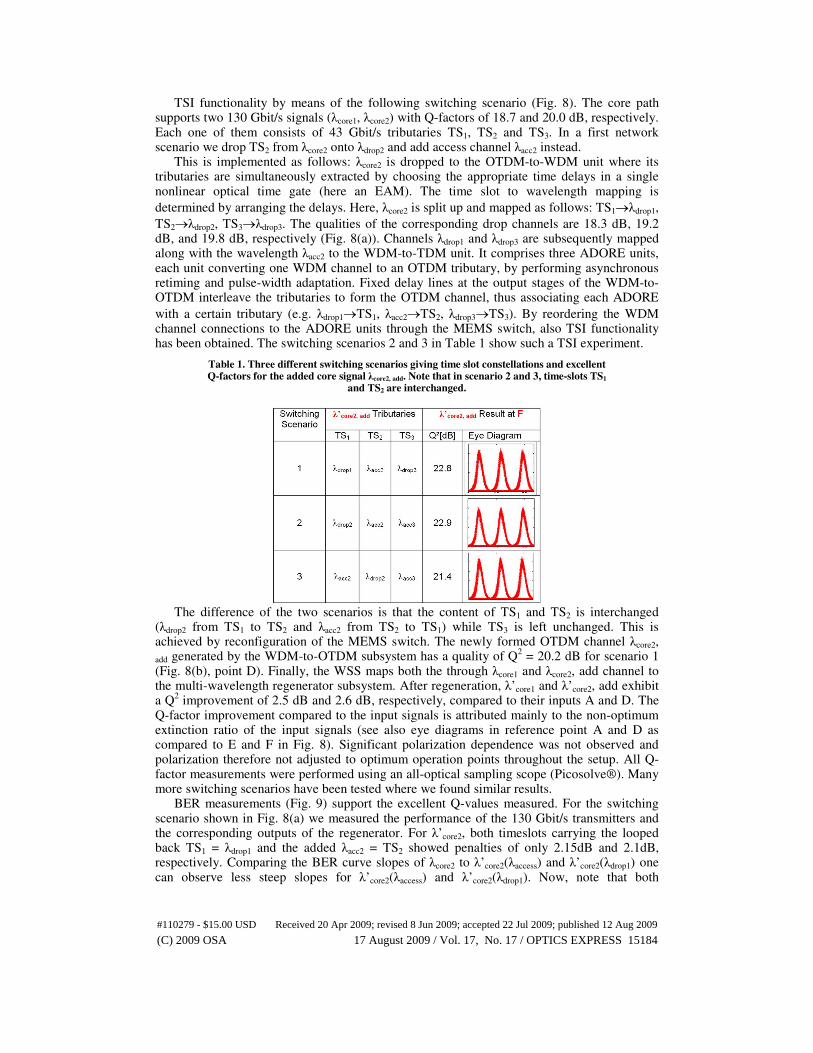
TSI functionality by means of the following switching scenario (Fig. 8). The core path supports two 130 Gbit/s signals (λcore1, λcore2) with Q-factors of 18.7 and 20.0 dB, respectively. Each one of them consists of 43 Gbit/s tributaries TS1, TS2 and TS3. In a first network scenario we drop TS2 from λcore2 onto λdrop2 and add access channel λacc2 instead.
This is implemented as follows: λcore2 is dropped to the OTDM-to-WDM unit where its tributaries are simultaneously extracted by choosing the appropriate time delays in a single nonlinear optical time gate (here an EAM). The time slot to wavelength mapping is
determined by arranging the delays. Here, λcore2 is split up and mapped as follows: TS1→λdrop1,
TS2→λdrop2, TS3→λdrop3. The qualities of the corresponding drop channels are 18.3 dB, 19.2 dB, and 19.8 dB, respectively (Fig. 8(a)). Channels λdrop1 and λdrop3 are subsequently mapped along with the wavelength λacc2 to the WDM-to-TDM unit. It comprises three ADORE units, each unit converting one WDM channel to an OTDM tributary, by performing asynchronous retiming and pulse-width adaptation. Fixed delay lines at the output stages of the WDM-to-OTDM interleave the tributaries to form the OTDM channel, thus associating each ADORE
with a certain tributary (e.g. λdrop1→TS1, λacc2→TS2, λdrop3→TS3). By reordering the WDM channel connections to the ADORE units through the MEMS switch, also TSI functionality has been obtained. The switching scenarios 2 and 3 in Table 1 show such a TSI experiment.
Table 1. Three different switching scenarios giving time slot constellations and excellent Q-factors for the added core signal λcore2, add. Note that in scenario 2 and 3, time-slots TS1
and TS2 are interchanged.
The difference of the two scenarios is that the content of TS1 and TS2 is interchanged
(λdrop2 from TS1 to TS2 and λacc2 from TS2 to TS1) while TS3 is left unchanged. This is achieved by reconfiguration of the MEMS switch. The newly formed OTDM channel λcore2,
add generated by the WDM-to-OTDM subsystem has a quality of Q2 = 20.2 dB for scenario 1
(Fig. 8(b), point D). Finally, the WSS maps both the through λcore1 and λcore2, add channel to the multi-wavelength regenerator subsystem. After regeneration, λ’core1 and λ’core2, add exhibit a Q
2 improvement of 2.5 dB and 2.6 dB, respectively, compared to their inputs A and D. The
Q-factor improvement compared to the input signals is attributed mainly to the non-optimum extinction ratio of the input signals (see also eye diagrams in reference point A and D as compared to E and F in Fig. 8). Significant polarization dependence was not observed and polarization therefore not adjusted to optimum operation points throughout the setup. All Q-factor measurements were performed using an all-optical sampling scope (Picosolve®). Many more switching scenarios have been tested where we found similar results.
BER measurements (Fig. 9) support the excellent Q-values measured. For the switching scenario shown in Fig. 8(a) we measured the performance of the 130 Gbit/s transmitters and the corresponding outputs of the regenerator. For λ’core2, both timeslots carrying the looped back TS1 = λdrop1 and the added λacc2 = TS2 showed penalties of only 2.15dB and 2.1dB, respectively. Comparing the BER curve slopes of λcore2 to λ’core2(λaccess) and λ’core2(λdrop1) one can observe less steep slopes for λ’core2(λaccess) and λ’core2(λdrop1). Now, note that both
#110279 - $15.00 USD Received 20 Apr 2009; revised 8 Jun 2009; accepted 22 Jul 2009; published 12 Aug 2009
(C) 2009 OSA 17 August 2009 / Vol. 17, No. 17 / OPTICS EXPRESS 15184

λ’core2(λaccess) and λ’core2(λdrop1) traverse the WDM-to-OTDM subsystem. Actually, similar slopes can be found when looking at the BER curves of the WDM-to-OTDM setup in Fig. 5(a). We therefore attribute the flat slopes of the BER curves of λ’core2(λaccess) and λ’core2(λdrop1) to this penalty. Even passing through the all-optical 2R regenerator does not correct for the bit errors that occurred during the digital WDM-to-OTDM conversion. The measurements were done with a PRBS of length 2
31-1.
Fig. 9. BER measurements for switching scenario 1. All measurements were taken using an EAM performing temporal demultiplexing from 130 Gbit/s to 43 Gbit/s.
5. Conclusion
A novel optical switching node with sub-rate traffic grooming and multi-wavelength regenerative capabilities has been successfully demonstrated. It provides interconnection of high bit-rate 130 Gbit/s core rings with lower bit-rate 43 Gbit/s metro rings. The TRIUMPH switch node is expected to boost the progress in the metro networks and to match the technological leaps that have already been carried out at the backbone and the access parts. This approach does not only offer broadband access for every user but also interoperability with existing infrastructures providing a smooth migration path from existing to future infrastructures and supporting a variety of new services and applications. One key to the success of this demonstration was the exploitation of nonlinearities in HNLF. An alternative approach could be the use of short silicon-organic hybrid slot waveguides with a record
nonlinearity coefficient of γ ≈1 × 10⁵ W
−1 km
−1 [27]. In view of the potential for improving
fiber-chip coupling and waveguide loss, this technology could be key for offering higher bandwidth and less power consuming subsystems in the future.
Acknowledgements
This work was supported by the European projects TRIUMPH (grant IST-027638 STP) and in part by Euro-Fos (NoE 224402) and the Science Foundation Ireland (grant 06/IN/I969).
#110279 - $15.00 USD Received 20 Apr 2009; revised 8 Jun 2009; accepted 22 Jul 2009; published 12 Aug 2009
(C) 2009 OSA 17 August 2009 / Vol. 17, No. 17 / OPTICS EXPRESS 15185