Optical Fiber Communications Optical Networks. Network Terminology Stations are devices that network...
46
Optical Fiber Communications Optical Networks
-
Upload
marilyn-atkins -
Category
Documents
-
view
218 -
download
0
Transcript of Optical Fiber Communications Optical Networks. Network Terminology Stations are devices that network...

Optical Fiber Communications
Optical Networks

Network Terminology• Stations are devices that network subscribers use to communicate.• A network is a collection of interconnected stations.• A node is a point where one or more communication lines terminate.• A trunk is a transmission line that supports large traffic loads.• The topology is the logical manner in which nodes are linked together by
information transmitting channels to form a network.
2

Segments of a Public Network• A local area network interconnects users in a large room or work area, a department, a
home, a building, an office or factory complex, or a group of buildings.• A campus network interconnects a several LANs in a localized area.• A metro network interconnects facilities ranging from buildings located in several city
blocks to an entire city and the metropolitan area surrounding it.• An access network encompasses connections that extend from a centralized switching
facility to individual businesses, organizations, and homes.
3

Protocol Stack Model• The physical layer refers to a physical transmission medium• The data link layer establishes, maintains, and releases links that directly
connect two nodes• The function of the network layer is to deliver data packets from source to
destination across multiple network links.
4

Network Layering Concept• Network architecture: The general physical arrangement and
operational characteristics of communicating equipment together with a common set of communication protocols
• Protocol: A set of rules and conventions that governs the generation, formatting, control, exchange, and interpretation of information sent through a telecommunication network or that is stored in a database
• Protocol stack: Subdivides a protocol into a number of individual layers of manageable and comprehensible size– The lower layers govern the communication facilities.– The upper layers support user applications by structuring and
organizing data for the needs of the user.
5

Optical LayerThe optical layer is a wavelength-based concept and lies just above the physical layer•The physical layer provides a physical connection between two nodes•The optical layer provides light path services over that link
•The optical layer processes include wavelength multiplexing, adding and dropping wavelengths, and support of optical switching
6

Synchronous Optical Networks• SONET is the TDM optical network standard
for North America • SONET is called Synchronous Digital
Hierarchy (SDH) in the rest of the world• SONET is the basic phycal layer standard• Other data types such as ATM and IP can be
transmitted over SONET• OC-1 consists of 810 bytes over 125 us; OC-
n consists of 810n bytes over 125 us • Linear multiplexing and de-multiplexing is
possible with Add-Drop-Multiplexers
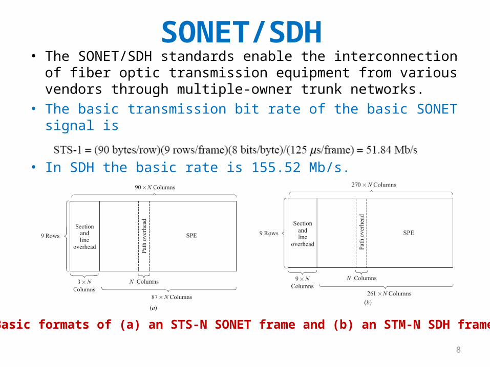
SONET/SDH• The SONET/SDH standards enable the interconnection of fiber
optic transmission equipment from various vendors through multiple-owner trunk networks.
• The basic transmission bit rate of the basic SONET signal is
• In SDH the basic rate is 155.52 Mb/s.
8
Basic formats of (a) an STS-N SONET frame and (b) an STM-N SDH frame

Common values of OC-N and STM-N• OC stands for optical carrier. It has become common to refer
to SONET links as OC-N links.• The basic SDH rate is 155.52 Mb/s and is called the
synchronous transport module—level 1 (STM-1).
9

Not to be confused with Wavelength ADM
SONET Add Drop Multiplexers
SONET ADM is a fully synchronous, byte oriented device, that can be used add/drop OC sub-channels within an OC-N signal
Ex: OC-3 and OC-12 signals can be individually added/dropped from an OC-48 carrier

SONET/SDH Rings• SONET and SDH can be configured as either a ring or mesh architecture• SONET/SDH rings are self-healing rings because the traffic flowing along a
certain path can be switched automatically to an alternate or standby path following failure or degradation of the link segment
• Two popular SONET and SDH networks:– 2-fiber, unidirectional, path-switched ring (2-fiber UPSR)– 2-fiber or 4-fiber, bidirectional, line-switched ring (2-fiber or 4-fiber BLSR)
Generic 2-fiber UPSR with a counter-rotatingprotection path

2-Fiber UPSR Basics
Ex: Total capacity OC-12 may be divided to four OC-3 streams, the OC-3 is called a path here
Node 1-2OC-3
Node 2-4; OC-3

2-Fiber UPSR Protection
• Rx compares the signals received via the primary and protection paths and picks the best one
• Constant protection and automatic switching

BLSR Recovery from Failure Modes
• If a primary-ring device fails in either node 3 or 4, the affected nodes detect a loss-of-signal condition and switch both primary fibers connecting these nodes to the secondary protection pair
• If an entire node fails or both the primary and protection fibers in a given span are severed, the adjacent nodes switch the primary-path connections to the protection fibers, in order to loop traffic back to the previous node.
14

4-Fiber BLSR Basics
Node 13; 1p, 2p Node 31; 3p, 4p
All
seco
ndar
y fib
er le
ft f
or p
rote
ctio
n

BLSR Fiber-Fault Reconfiguration
In case of failure, the secondary fibers between only the affected nodes (3 & 4) are used, the other links remain unaffected
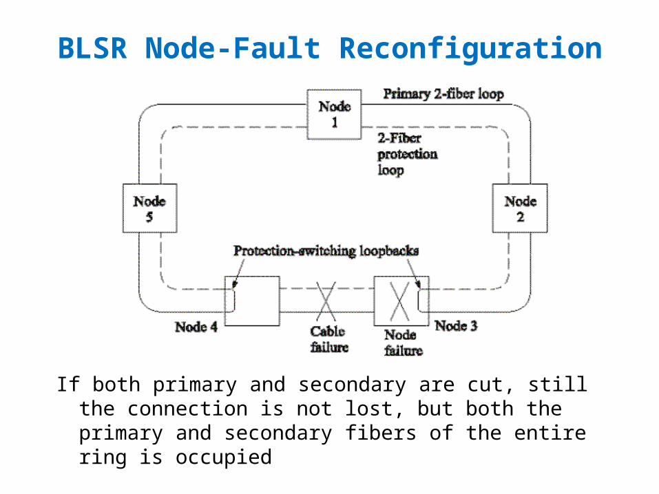
BLSR Node-Fault Reconfiguration
If both primary and secondary are cut, still the connection is not lost, but both the primary and secondary fibers of the entire ring is occupied

Generic SONET networkLarge National Backbone
City-wide
Local Area
Versatile SONET equipmentare available that support wide range of configurations, bit rates and protection schemes
Passive Optical Networks
• In general, there is no O/E conversion between the transmitter and the receiver (one continuous light path) in PON networks
• Only passive elements used to configure the network• Power budget and rise time calculations has to be done
from end-to-end• There are star, bus, ring, mesh & tree topologies• Currently PON Access Networks are deployed widely and
the word PON means mainly the access nw.
The PON will still need higher layer protocols (Ethernet/IP etc.) to separate multiple users

Basic PON Topologies
BUS
RING
STAR

Star, Tree & Bus Networks
• Tree networks are widely deployed in the access front
• Tree couplers are similar to star couplers (expansion in only one direction; no splitting in the uplink)
• Bus networks are widely used in LANs
• Ring networks (folded buses with protection) are widely used in MAN
• Designing ring & bus networks is similar

Network Elements of PON• Passive Power Coupler/Splitter: Number of
input/output ports and the power is split in different ratios. – Ex: 2X2 3-dB coupler; 80/20 coupler
• Star Coupler: Splits the incoming power into number of outputs in a star network
• Add/Drop Bus Coupler: Add or drop light wave to/from an optical bus
• All Optical Switch: Divert the incoming light wave into a particular output

Star Network
Power Budget:
Worst case power budget need to be satisfied
Ps-Pr = 2lc + α(L1+L2) + Excess Loss + 10 Log N + System Margin

Linear Bus Network
,
10log ( 1) 2 ( 2) 2oC thru TAP i
L N
PN L NL N L L NL
P
Ex. 12.1

Add-Drop Bus-Coupler Losses
Connector loss (Lc) = 10Log (1-Fc)Tap loss (Ltap) = -10 Log (CT) Throughput loss (Lth) = -20 Log (1-CT) Intrinsic loss (Li) = -10 Log (1-Fi)

Linear Bus versus Star Network
• The loss linearly increases with N in bus networks while it is almost constant in star networks (Log(N))
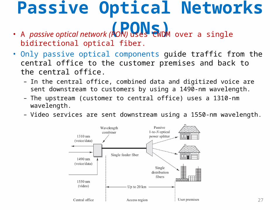
Passive Optical Networks (PONs)• A passive optical network (PON) uses CWDM over a single
bidirectional optical fiber. • Only passive optical components guide traffic from the central
office to the customer premises and back to the central office. – In the central office, combined data and digitized voice are sent
downstream to customers by using a 1490-nm wavelength. – The upstream (customer to central office) uses a 1310-nm wavelength. – Video services are sent downstream using a 1550-nm wavelength.
27

Active PON Modules• The optical line termination (OLT) is located in a central office and controls
the bidirectional flow of information across the network.• An optical network termination (ONT) is located directly at the customer
premises.– The ONT provides an optical connection to the PON on the upstream
side and to interface electrically to the local customer equipment.• An optical network unit (ONU) is similar to an ONT, but is located near the
customer and is housed in an outdoor equipment shelter.
28

PON Protection Methods
PON failure protection mechanisms include a fully redundant 1 + 1 protection and a partially redundant 1:N protection.
29

WDM Networks• Single fiber transmits multiple
wavelengths WDM Networks• One entire wavelength (with all the data)
can be switched/routed • This adds another dimension; the
Optical Layer• Wavelength converters/cross
connectors; all optical networks• Note protocol independence

Basic WDM PON Architectures
• Broadcast and Select: employs passive optical stars or buses for local networks applications– Single hop networks– Multi hop networks
• Wavelength Routing: employs advanced wavelength routing techniques– Enable wavelength reuse– Increases capacity

Single hop broadcast and select WDM
• Each Tx transmits at a different fixed wavelength• Each receiver receives all the wavelengths, but
selects (decodes) only the desired wavelength• Multicast or broadcast services are supported• Dynamic coordination between the TX & RX and
tunable filters at the receivers are required
Star Bus

A Single-hop Multicast WDM Network
Multiple receivers may be listening to the same wavelength simultaneously
The drawback in single hop WDM networks, Number of nodes = Number of wavelengths
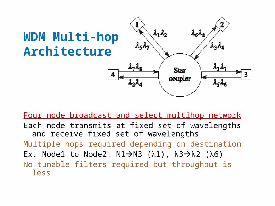
WDM Multi-hop Architecture
Four node broadcast and select multihop networkEach node transmits at fixed set of wavelengths and
receive fixed set of wavelengthsMultiple hops required depending on destinationEx. Node1 to Node2: N1N3 (1), N3N2 (6) No tunable filters required but throughput is less

Data Packet
In multihop networks, the source and destination information is embedded in the header
These packets may travel asynchronously (Ex. ATM)

Shuffle Net
Shuffle Net a popular multihop topology
N = (# of nodes) X (per node)
Max. # of hops = 2(#of-columns) –1
(-) Large # of ’s
(-) High splitting lossEx: A two column shuffle netMax. 2 X 2 - 1= 3 hops between any two nodes

Wavelength Routing
• The limitation is overcome by: – reuse, – routing and – conversion
• As long as the logical paths between nodes do not overlap they can use the same
Most long haul networks use wavelength routing WL Routing requires optical switches, cross connects etc.

Optical Add/Drop Multiplexing• An optical add/drop multiplexer (OADM) allows the insertion or extraction
of one or more wavelengths from a fiber at a network node.• Most OADMs are constructed using WDM elements such as a series of
dielectric thin-film filters, an AWG, a set of liquid crystal devices, or a series of fiber Bragg gratings used in conjunction with optical circulators.
• The OADM architecture depends on factors such as the number of wavelengths to be dropped/added, the OADM modularity for upgrading flexibility, and what groupings of wavelengths should be processed.
38

Reconfigurable OADM (ROADM)• ROADMs can be reconfigured by a network operator within
minutes from a remote network-management console.• ROADM architectures include wavelength blockers, arrays of
small switches, and wavelength-selective switches.• ROADM features:
– Wavelength dependence. When a ROADM is independent of wavelength, it is colorless or has colorless ports.
– ROADM degree is the number of bidirectional multiwavelength interfaces the device supports. Example: A degree-2 ROADM has 2 bidirectional WDM interfaces and a degree-4 ROADM supports 4 bidirectional WDM interfaces.
– Express channels allow a selected set of wavelengths to pass through the node without the need for OEO conversion.
39

Wavelength Blocker Configuration
The simplest ROADM configuration uses a broadcast-and-select approach:
40

Optical Burst Switching• Optical burst switching provides an efficient solution for
sending high-speed bursty traffic over WDM networks.• Bursty traffic has long idle times between the busy periods in
which a large number of packets arrive from users.
41

A 12X12 Optical Cross-Connect (OXC)
Incoming wavelengths can be dropped or routed to any desired output

Optical Cross Connects (OXC)
• Works on the optical domain• Can route high capacity wavelengths• Switch matrix is controlled electronically• Incoming wavelengths are routed either to
desired output (ports 1-8) or dropped (9-12)• Local wavelengths can be added• What happens when both incoming fibers have
a same wavelength? (contention)

Ex: 4X4 Optical cross-connect
Wavelength switches are electronically configuredWavelength conversion to avoid contention

IP over DWDM• Early IP networks had redundant management functions in each layer, so
this layering method was not efficient for transporting IP traffic.• An IP-SONET-DWDM architecture using Multiprotocol Label Switching
(MPLS) provides for the efficient designation, routing, forwarding, and switching of traffic flows through the network.

Optical Ethernet• The IEEE has approved the 802.3ah Ethernet in the First Mile (EFM) standard. • The first mile is the network infrastructure that connects business or
residential subscribers to the CO of a telecom carrier or a service provider.
Three EFM physical transport schemes are:1.Individual point-to-point (P2P) links2.A single P2P link to multiple users3.A single bidirectional PON