
Optical Fiber Cable.ppt
61
For internal use only National Transmission Team / 03/13/22 1 © Nokia Siemens Networks Optical Fiber Cable(OFC) By :- NATIONAL TRANSMISSION TEAM Ankush Sharma Paras
-
Upload
navin-kumar -
Category
Documents
-
view
406 -
download
8
Transcript of Optical Fiber Cable.ppt

For internal use onlyNational Transmission Team / 04/20/23 1 © Nokia Siemens Networks
Optical Fiber Cable(OFC)
By :-
NATIONAL TRANSMISSION TEAM
Ankush Sharma
Paras Malhotra

For internal use onlyNational Transmission Team / 04/20/23 2 © Nokia Siemens Networks
Growth Of Optical Fiber
o Optical fibers were discovered in 1920s
o Initially they were used for medical purposes but seldom used for communication purposes due to high losses.
o By 1960, glass-clad fibers had attenuation of about one decibel per meter, fine for medical imaging, but too high for communications .
o By 1980 the carriers built national backbone network of optical fiber with 1300nm sources where fiber attenuation was as low as 0.5 dB/km
o However, a new generation of single-mode systems is now beginning to find applications in submarine cables and systems serving large numbers of subscribers. They operate at 1.55 micrometers, where fiber loss is 0.2 to 0.3 dB/km, allowing even longer repeater spacings.

For internal use onlyNational Transmission Team / 04/20/23 3 © Nokia Siemens Networks
What are Optical Fibers?
Optical Fibers are thin long (km) strands of ultra pure glass (silica) or plastic that can to transmit light from one end to another without much attenuation or loss.
This is to be believed as repeater distances on long haul routes for optical fibers vary from 50 to 150 km.

For internal use onlyNational Transmission Team / 04/20/23 4 © Nokia Siemens Networks
Basic Concept Behind OFC Communication
A fiber-optic system is similar to the copper wire system that fiber-optics is replacing. The difference is that fiber-optics use light pulses to transmit information down fiber lines instead of using electronic pulses to transmit information down copper lines
Fiber optic cable functions as a "light guide," guiding the light introduced at one end of the cable through to the other end. The light source can either be a light-emitting diode (LED)) or a laser.
The light source is pulsed on and off, and a light-sensitive receiver on the other end of the cable converts the pulses back into the digital ones and zeros of the original signal.
For internal use onlyNational Transmission Team / 04/20/23 5 © Nokia Siemens Networks
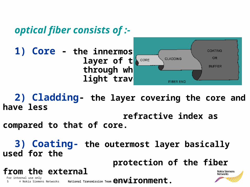
optical fiber consists of :-
1) Core - the innermost layer of the fiber through which light travels.
2) Cladding- the layer covering the core and have less refractive index as compared to that of core.
3) Coating- the outermost layer basically used for the protection of the fiber from the external environment.
National Transmission Team /

For internal use onlyNational Transmission Team / 04/20/23 6 © Nokia Siemens Networks
Working Principle of Optical Fiber:
Optical fiber works on the principle of Total Internal Reflection.
Total internal reflection is an optical phenomenon that occurs when a ray of light strikes a medium boundary at an angle larger than a particular critical angle with respect to the normal to the surface. If the refractive index is lower on the other side of the boundary, no light can pass through and all of the light is reflected. The critical angle is the angle of incidence above which the total internal reflection occurs.

For internal use onlyNational Transmission Team / 04/20/23 7 © Nokia Siemens Networks
Total internal refection confines light within optical fibers (similar to looking down a mirror made in the shape of a long paper towel tube). Because the cladding has a lower refractive index, light rays reflect back into the core if they encounter the cladding at a shallow angle (red lines). A ray that exceeds a certain "critical" angle (c) escapes from the fiber (yellow line).

For internal use onlyNational Transmission Team / 04/20/23 8 © Nokia Siemens Networks National Transmission Team /
Types of optical fiber
Optical fiber is of two types :-
1)Step Index Fiber –This kind of fiber has uniform refractive index within the core and there is a sharp decrease in refractive index at the core-cladding interface.
2)Graded Index Fiber - It is an optical fiber whose core has a refractive index that decreases with increasing radial distance from the fiber axis (the imaginary central axis running down the length of the fiber). Because parts of the core closer to the fiber axis have a higher refractive index than the parts near the cladding, light rays follow sinusoidal paths down the fiber.

For internal use onlyNational Transmission Team / 04/20/23 9 © Nokia Siemens Networks
Step-index Multimode Fiber
core diameter = 50 – 200 µm
cladding diameter = 125-400 µm
STEP-INDEX MULTIMODE FIBER has a large core, as a result, some of the light rays that make up the digital pulse may travel a direct route, whereas others zigzag as they bounce off the cladding. These alternative pathways cause the different groupings of light rays, referred to as modes, to arrive separately at a receiving point.. Consequently, this type of fiber is best suited for transmission over short distances, in an endoscope, for instance.

For internal use onlyNational Transmission Team / 04/20/23 10 © Nokia Siemens Networks
Graded-index Multimode Fiber
core diameter = 50 – 100 µm
cladding diameter = 125-400 µm
GRADED-INDEX MULTIMODE FIBER contains a core in which the refractive index diminishes gradually from the center axis out towards the cladding. The higher refractive index at the center makes the light rays moving down the axis advance more slowly than those near the cladding. Also, rather than zigzagging off the cladding, light in the core curves helically because of the graded index, reducing its travel distance. The shortened path and the higher speed allow light at the periphery to arrive at a receiver at about the same time as the slow but straight rays in the core axis. The result: a digital pulse suffers less dispersion.
For internal use onlyNational Transmission Team / 04/20/23 11 © Nokia Siemens Networks
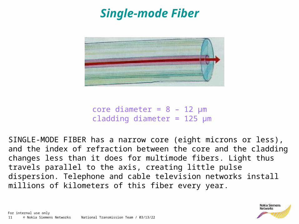
Single-mode Fiber
core diameter = 8 – 12 µm cladding diameter = 125 µm
SINGLE-MODE FIBER has a narrow core (eight microns or less), and the index of refraction between the core and the cladding changes less than it does for multimode fibers. Light thus travels parallel to the axis, creating little pulse dispersion. Telephone and cable television networks install millions of kilometers of this fiber every year.

For internal use onlyNational Transmission Team / 04/20/23 12 © Nokia Siemens Networks
Diameter of core in different Fiber modes

For internal use onlyNational Transmission Team / 04/20/23 13 © Nokia Siemens Networks
Mode Field Diameter
Mode-field diameter is a measure of the spot size or beam width of light propagating in a single-mode fiber . Mode-field diameter is a function of source wavelength, fiber core radius, and fiber refractive index profile. The vast majority of the optical power propagates within the fiber core, and a small portion
propagates in the cladding near the core as shown in the fig.
Energy Distribution in core
and cladding

For internal use onlyNational Transmission Team / 04/20/23 14 © Nokia Siemens Networks
Comparison With Other Media / Technologies

For internal use onlyNational Transmission Team / 04/20/23 15 © Nokia Siemens Networks
Advantages Of Optical Fibers
1. Very high information carrying capacity.
2. LESS ATTENUATION (order of 0.2 db/km)
3. Small in diameter and size & light weight
4. LOW COST AS COMPARED TO COPPER (as glass is made from sand, the raw material used to make OF is free….)
5. Greater safety and immune to emi & rfi, moisture & corossion
6. Flexible and easy to install in tight conduicts
7. ZERO RESALE VALUE (so theft is less)
8. Is dielectric in nature so can be laid in electrically sensitive surroundings
9. Difficult to tap fibers, so secure
10. No cross talk and disturbances

For internal use onlyNational Transmission Team / 04/20/23 16 © Nokia Siemens Networks
Disadvantages Of Optical Fibers…1.The terminating equipment is still costly as compared to
copper equipment.
2.Optical Fiber is delicate so has to be handled carefully.
3.Last mile is still not totally fiberised due to costly subscriber premises equipment.
4.Communication is not totally in optical domain, so repeated electric –optical – electrical conversion is needed.
5.Tapping is not possible. Specialized equipment is needed to tap a fiber.
6.Optical fiber splicing is a specialized technique and needs expertly trained manpower.
7.The splicing and testing equipments are very expensive as compared to copper equipments.

For internal use onlyNational Transmission Team / 04/20/23 17 © Nokia Siemens Networks
Applications Of Optical Fibers…
1. LONG DISTANCE COMMUNICATION BACKBONES
2. VIDEO TRANSMISSION
3. BROADBAND SERVICES
4. COMPUTER DATA COMMUNICATION (LAN, WAN etc..)
5. HIGH EMI AREAS
6. MILITARY APPLICATION
7.NON-COMMUNICATION APPLICATIONS (sensors etc…)

For internal use onlyNational Transmission Team / 04/20/23 18 © Nokia Siemens Networks
Optical Fiber Cable
In practical fibers, the cladding is usually coated with a tough resin buffer layer, which may be further surrounded by a jacket layer, usually plastic. These layers add strength to the fiber but do not contribute to its optical wave guide properties. Rigid fiber assemblies sometimes put light-absorbing ("dark") glass between the fibers, to prevent light that leaks out of one fiber from entering another. This reduces cross-talk between the fibers.

For internal use onlyNational Transmission Team / 04/20/23 19 © Nokia Siemens Networks
Various Types Of Optical Fiber Cables
OPGW (Optical Pilot Ground Wire) Cable Self-Support AERIAL figure 8 type OF Cable Cable ADSS (All Dielectric Self Supported) type OF Cable LASHED type OF Cable UNDERGROUND / BURRIED type OF Cables DUCT Type OF Cable

For internal use onlyNational Transmission Team / 04/20/23 20 © Nokia Siemens Networks

For internal use onlyNational Transmission Team / 04/20/23 21 © Nokia Siemens Networks

For internal use onlyNational Transmission Team / 04/20/23 22 © Nokia Siemens Networks

For internal use onlyNational Transmission Team / 04/20/23 23 © Nokia Siemens Networks
Downlead clamps
Stockbridge Damper
Suspension assembly
They are used to fix the cable to the tower in the down lead to the joint box.
Assembly with reinforced suspension clamp and neoprene inner covering, especially designed for OPGW cables. Includes grounding clamps for tower connection.
The dampers are used to absorb the cable vibrations.

For internal use onlyNational Transmission Team / 04/20/23 24 © Nokia Siemens Networks

For internal use onlyNational Transmission Team / 04/20/23 25 © Nokia Siemens Networks
AERIAL Figure 8 type OF Cable

For internal use onlyNational Transmission Team / 04/20/23 26 © Nokia Siemens Networks

For internal use onlyNational Transmission Team / 04/20/23 27 © Nokia Siemens Networks

For internal use onlyNational Transmission Team / 04/20/23 28 © Nokia Siemens Networks
LASHED type OF Cable

For internal use onlyNational Transmission Team / 04/20/23 29 © Nokia Siemens Networks
UNDERGROUND / BURRIED Type OF Cables

For internal use onlyNational Transmission Team / 04/20/23 30 © Nokia Siemens Networks
DUCT Type OF Cable

For internal use onlyNational Transmission Team / 04/20/23 31 © Nokia Siemens Networks
Submarine
Communication
Cable

For internal use onlyNational Transmission Team / 04/20/23 32 © Nokia Siemens Networks
Submarine communication cable
A submarine communication cable is a cable laid beneath the sea to carry telecommunications between countries. A cross section of a submarine communications cable is as follows :-
1 - Polyethylene2 - Mylar tape3 - Stranded steel wires4 - Aluminium water barrier5 - Polycarbonate6 - Copper or aluminium tube7 - Petroleum jelly8 - Optical fibers

For internal use onlyNational Transmission Team / 04/20/23 33 © Nokia Siemens Networks
Importance of Submarine Cables
As of 2006, overseas satellite links accounted carried only 1 percent of international traffic, while the remainder was carried by undersea cable. The reliability of submarine cables is high, especially when multiple paths are available in the event of a cable break. Also, the total carrying capacity of submarine cables is in the terabits per second while satellites typically offer only megabits per second and display higher latency. However, a typical multi-terabit, transoceanic submarine cable system costs several hundred million dollars to construct.
For more details on submarine cables and its installation refer to theattached document. submarine cables

For internal use onlyNational Transmission Team / 04/20/23 34 © Nokia Siemens Networks
Decommissioning reason: This cable destroyed after one month of operation due to the
excessive voltage applies to the cable in order to achieve faster telegraph operation.
SEA-ME-WE 1 SEA-ME-WE 2 SEA-ME-WE 3 SEA-ME-WE 4
Commissioned in
Jun-1985 Oct-1994Aug-1999 Nov-2005
(Decommissioned (Decommissioned
June 1999) October 2006)
Capacity/Length12MHz 2x560Mbps 8x2.5Gbps 64x2x10Gbps
13,500km 18,000km 39,000km 20,000km
No. of Owners 22 52 92 16
Total InvestmentUSD800M USD800M USD1500M USD500M
TechnologyAnalog/Copper PDH/Optical
SDH/WDM/Optical
SDH/DWDM/Optical

For internal use onlyNational Transmission Team / 04/20/23 35 © Nokia Siemens Networks
South East Asia–Middle East–Western Europe 4 (SEA-ME-WE 4) Cable
It is an optical fiber submarine communications cable system that carries telecommunications between Singapore, Malaysia , Thailand , Bangladesh, India, SriLanka, Pakistan, United Arab Emirates, Saudi Arabia, Sudan ,Egypt, Italy ,Tunisia, Algeria and France.
The cable is approximately 18,800 kilometres long, and provides the primary Internet backbone between South East Asia, Indian subcontinent , Middle East and Europe.
The cable uses dense wavelength-division multiplexing (DWDM), allowing for increased communications capacity per fibre compared to fibres carrying non-multiplexed signals and also facilitates bidirectional communication within a single fibre.
Two fibre pairs are used with each pair able to carry 64 carriers at 10 Gbit/s each. This enables terabit per second speeds along the SEA-WE-ME 4 cable with a total capacity of 1.28 Tbit/s.
SEA-ME-WE 4 is used to carry "telephone, internet, multimedia and various broadband data applications

For internal use onlyNational Transmission Team / 04/20/23 36 © Nokia Siemens Networks
Splicing
Splices are "permanent" connections between two fibers.
Splicing is only needed if the cable runs are too long for one straight pull or you need to mix a number of different types of cables (like bringing a 48 fiber cable in and splicing it to six 8 fiber cables).
Video shows the steps for Splicing:
1. Physical Preparation
2. Stripping, Cleaving and cleaning the fiber with Iso propyl Alcohol.
3. Splicing the fiber.
4. Heating the Splice with Sleeve.
5. Routing the spliced fiber in Joint Closure
For internal use onlyNational Transmission Team / 04/20/23 37 © Nokia Siemens Networks
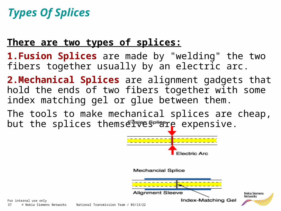
Types Of Splices
There are two types of splices:
1.Fusion Splices are made by "welding" the two fibers together usually by an electric arc.
2.Mechanical Splices are alignment gadgets that hold the ends of two fibers together with some index matching gel or glue between them.
The tools to make mechanical splices are cheap, but the splices themselves are expensive.

For internal use onlyNational Transmission Team / 04/20/23 38 © Nokia Siemens Networks
Which Splice?
If cost is the issue, we've given you the clues to make a choice: fusion is expensive equipment and cheap splices, while mechanical is cheap equipment and expensive splices.
So if you make a lot of splices (like thousands in an big telco or CATV network) use fusion splices. If you need just a few, use mechanical splices.
Fusion splices give very low back reflections and are preferred for singlemode high speed digital or CATV networks. However, they don't work too well on multimode splices, so mechanical splices are preferred for MM, unless it is an underwater or aerial application, where the greater reliability of the fusion splice is preferred.

For internal use onlyNational Transmission Team / 04/20/23 39 © Nokia Siemens Networks
Connectors The connector is a mechanical device mounted on the end of a fiber-optic cable, light source, receiver, or housing. The connector allows the fiber-optic cable, light source, receiver, or housing to be mated to a similar device. The connector must direct light and collect light and must be easily attached and detached from equipment.
Types Of Connectors
ST (Straight Tip) most popular connector for multimode networks
FC/PC(Ferrule Connection) most popular singlemode connectors)
SC (Square Connector ) is a snap-in connector , widely used in singlemode systems
LC(Lucent Connector) is a new connector that uses a 1.25 mm ferrule
E2000/LX-5 is like a LC but with a shutter over the end of the fiber

For internal use onlyNational Transmission Team / 04/20/23 40 © Nokia Siemens Networks
Optical Fiber CharacteristicsOptical Fiber Characteristics
Mostly SM fiber is used for long distance communication
typically 5 Km to 170 Km without any problem
MM fiber is only used for the low data rates and short
distance communication typically 100 meter to 1 Km
Distance of reach depends on so many parameters

For internal use onlyNational Transmission Team / 04/20/23 41 © Nokia Siemens Networks
Typical SM Fiber Parameters
Attenuation slope (dB/Km/nm) Dispersion slope (ps/nm2 Km) Mode field diameter

For internal use onlyNational Transmission Team / 04/20/23 42 © Nokia Siemens Networks
0.10.2
0.5
1.02.0
5.0
10
20
50
100
800600 12001000 16001400 1800
Early 1970s
First Window
Second Window Third
Window1980s
Wavelength (nm)
Att
enu
atio
n
(dB
/km
)
Attenuation vs WavelengthAttenuation vs Wavelength

For internal use onlyNational Transmission Team / 04/20/23 43 © Nokia Siemens Networks
Signal distortion due to chromatic dispersion
Spectrum broadening
Difference in group velocity
WavelengthGro
up
vel
oci
ty
Δλ
1
Time
1 0
Original signal
Time
Transmitter output
Time
Receiver input
Time
111Regenerated signal
Wavelength
Optical spectrum
Δλ
Pulse broadening(Waveform distortion)
Optical fiber

For internal use onlyNational Transmission Team / 04/20/23 44 © Nokia Siemens Networks
Waveform distortion due to fiber non-linearity
High power intensity
Frequencychirp
Refractive index change
Waveform distortion due to chromatic dispersion
Optical fiber
Spectrumbroadening
Transmitter out
Received waveform
Low optical power
High optical power

For internal use onlyNational Transmission Team / 04/20/23 45 © Nokia Siemens Networks
After fiber transmission
40 Gb/s optical signal
Transmitter output
25 ps
Transmission fiber
Positive dispersion(Negative dispersion)
+Dispersion compensating fiber (DCF)
After dispersion comp.
Negative dispersion (Positive dispersion)
Longer wavelength
Slow (Fast)
Shorter wavelength
Fast (Slow)
Longer wavelength
Fast (Slow)
Shorter wavelength
Slow (Fast)
Dispersion Compensation Example

For internal use onlyNational Transmission Team / 04/20/23 46 © Nokia Siemens Networks
Polarization Mode Dispersion (PMD)
- Well defined, frequency independent eigenstates
- Deterministic, frequency independent Differential Group Delay (DGD)
- DGD scales linearity with fiber length
1st-order PMD
Ideal Practical
Core
Cladding
Cross-section of optical fiber
Fast axis
Slow axis
Fast
Slow
Differential Group Delay (DGD)

For internal use onlyNational Transmission Team / 04/20/23 47 © Nokia Siemens Networks
Automatic PMD compensation
PMD characteristic changes slowly due to “normal” environmental fluctuations (e.g. temperature)
But, fast change due to e.g. fiber touching
High-speed PMD compensation device & Intelligent control algorithm
PMD compensation scheme in receiver
Before PMD comp.
After PMD comp.
40Gb/s waveforms
Distortionanalyzer
Controlalgorithm
PMDcomp.
device #3
PMDcomp.
device #2
PMDcomp.
device #1
O/Emodule

For internal use onlyNational Transmission Team / 04/20/23 48 © Nokia Siemens Networks
Maximum Permissible Loss
1) Connector Loss :- .3db loss for most
adhesive/polish connect .75 max. as per EIA/TIA 568
2) Splice Loss :- less than .5db for mechanical
splice less than .3db loss for each
fusion splice as per EIA/TIA 568
3) Fiber Loss :-
Single mode Multi mode
.5db per km for 1300 nm
3db per km for 850 nm
.4db per km at 1550 nm
1db per km for 1300 nm

For internal use onlyNational Transmission Team / 04/20/23 49 © Nokia Siemens Networks
ITU Standards (Optical Fiber)ITU Standards (Optical Fiber)
G.650 – Definition and test methods for the relevant parameters of single mode fibers
G.651 – Characteristics of a 50/125 μm multimode graded index optical fiber cable
G.652 – Characteristics of a single-mode optical fiber cable
G.653 – Characteristics of a dispersion-shifted single-mode optical fiber cable.
For internal use onlyNational Transmission Team / 04/20/23 50 © Nokia Siemens Networks
ITU Standards (Optical Fiber)ITU Standards (Optical Fiber)
G.654 – Characteristics of a 1550 nm wavelength loss- minimized single-mode optical fiber cable
G.655 – Characteristics of a non-zero dispersion single- mode optical fiber cable.

For internal use onlyNational Transmission Team / 04/20/23 51 © Nokia Siemens Networks
It is an optoelectronic instrument used to characterize an optical fiber. An OTDR injects a series of optical pulses into the fiber under test. It also extracts, from the same end of the fiber, light that is scattered and reflected back from points in the fiber where the index of refraction changes.
An OTDR is used for estimating the overall attenuation , including splice and mated-connector losses. It may also be used to locate faults, such as breaks, and to measure optical return loss.
OPTICAL TIME-DOMAIN REFLECTOMETER(OTDR)
Test And Measurement Instruments

For internal use onlyNational Transmission Team / 04/20/23 52 © Nokia Siemens Networks
SPLICING MACHINE
In fusion splicing a machine is used to precisely align the two fiber ends then the glass ends are "fused" or "welded" together using some type of heat or electric arc. This produces a continuous connection between the fibers enabling very low loss light transmission. (Typical loss: 0.1 dB)
An attenuator is an electronic device that reduces the amplitude or power of a signal without appreciably distorting its waveform.
ATTENUATOR

For internal use onlyNational Transmission Team / 04/20/23 53 © Nokia Siemens Networks
Other Measurement Tools
LASER SOURCE POWER METER
TOOL KIT

For internal use onlyNational Transmission Team / 04/20/23 54 © Nokia Siemens Networks
Furukawa Fujikura LG Cables Corning Philips-Fitel Pirelli TTL Sterlite Cables
Some Manufacturers Of Optical Cables

For internal use onlyNational Transmission Team / 04/20/23 55 © Nokia Siemens Networks
Basic Planning Parameters

For internal use onlyNational Transmission Team / 04/20/23 56 © Nokia Siemens Networks
Planning and Designing an OFC link
Route Survey & Design Extensive route survey is carried out prior to designing of the OFC network to obtain the following essential data :-
o Right of Way demarcation
o Soil strata
o Existing Underground utilities
o Road / Rail / Bridge / River / Canal Crossings
o Any other criticalities

For internal use onlyNational Transmission Team / 04/20/23 57 © Nokia Siemens Networks
Trenching Specifications for Excavation of Trenches
o Standard depth will be measured from lower side of natural ground level to the base of the trench.
o Standard depth for normal soil and soft rock: At least 1500 mm (1.5 M).o Standard depth for hard rock: At least 900 mm (0.9 M) .o Different clients have slightly marginal differences in trench depth.o Width of trench: 400mm at top and 300mm at the bottom.o When cable is to be laid along culverts/bridges or cross-streams, trench
may be made closer to road edge, or in some cases, over embankment or shoulder of the road.
o Line up of trench would be such that HDPE duct(s) will be laid in straight line, both laterally as well as vertically except at locations where it has to necessarily take a bend because of change in alignment or gradient of trench.
o Minimum radius of two meters will be maintained, where bends are necessitated.

For internal use onlyNational Transmission Team / 04/20/23 58 © Nokia Siemens Networks
Duct Laying
o Ducts will be laid in a flat bottom trench, free from stones, and sharp edged debris.
o The duct would be placed in trench as straight as possible. However, at bends horizontal and vertical minimum bending radius for duct of 1300 mm would be maintained.
o Ducts will be laid preferably using specially designed dispensers.
o Ducts shall be free from twist and collapsed portions.
o Ends of ducts will always be closed with END PLUGS to avoid ingress of mud, water or dust.
o Prior to aligning the ducts for jointing, each length of the HDPE duct will be thoroughly cleaned to remove all sand, dust or any other debris that may clog, disturb or damage the optical fiber cable when it is pulled or blown at a later stage.
o The ducts will be joined with couplers using duct cutter & other tools and will be tightened and secured properly.
o The duct joint will be practically airtight to ensure smooth cable blowing using cable blowing machines.

For internal use onlyNational Transmission Team / 04/20/23 59 © Nokia Siemens Networks
Back Fillingo Trench will be initially filled with sieved soil or sand in rocky terrain for
about 10 cm which will act as a cushion / padding and then duct is placed gently over it.
o After that another layer of 10 cm of fine sieved soil or sand is poured and then entire trench is backfilled with excavated material.
o Under normal soil conditions duct is directly laid in trench and backfilled. o Adequate dry compaction will be done before crowning.
Crowningo When backfilling has been done up to ground level a hump of soil is made
to cater for soil settlement.o Entire excavated soil will be used for back filling.o Crowning will be confined to width of trench only.
Groundingo The armoured layer of the fiber is cut down to provide grounding to the
complete cable path as well as to provide protection from lightining.o The cut is made after every 200 metres.

For internal use onlyNational Transmission Team / 04/20/23 60 © Nokia Siemens Networks
FMS Connectors
Fiber Management
System (FMS)
SJC BJC
TJCFiber Pigtail
TJC – Terminal Joint Connector
SJC – Straight Joint Closure
BJC- Branch Joint Closure
To
Eqpt.

For internal use onlyNational Transmission Team / 04/20/23 61 © Nokia Siemens Networks
Thanks
-National Transmission teamParas & Ankush


