Ethernet Passive Optical Network (EPON) : Building a Next- Generation Optical Access Network

Optical considerations for next-generation network
Inder Monga Executive Director, ESnet Division Director, Scientific Networking
Lawrence Berkeley National Lab
9th CEF Networks Workshop 2017
September 11th, 2017

Exponential growth is deceptive, and then explosive
9/14/2017 2

Ja
n 1
99
0
Ju
l 199
0
Ja
n 1
99
1
Ju
l 199
1
Ja
n 1
99
2
Ju
l 199
2
Ja
n 1
99
3
Ju
l 199
3
Ja
n 1
99
4
Ju
l 199
4
Ja
n 1
99
5
Ju
l 199
5
Ja
n 1
99
6
Ju
l 199
6
Ja
n 1
99
7
Ju
l 199
7
Ja
n 1
99
8
Ju
l 199
8
Ja
n 1
99
9
Ju
l 199
9
Ja
n 2
00
0
Ju
l 200
0
Ja
n 2
00
1
Ju
l 200
1
Ja
n 2
00
2
Ju
l 200
2
Ja
n 2
00
3
Ju
l 200
3
Ja
n 2
00
4
Ju
l 200
4
Ja
n 2
00
5
Ju
l 200
5
Ja
n 2
00
6
Ju
l 200
6
Ja
n 2
00
7
Ju
l 200
7
Ja
n 2
00
8
Ju
l 200
8
Ja
n 2
00
9
Ju
l 200
9
Ja
n 2
01
0
Ju
l 201
0
Ja
n 2
01
1
Ju
l 201
1
Ja
n 2
01
2
Ju
l 201
2
Ja
n 2
01
3
Ju
l 201
3
Ja
n 2
01
4
Ju
l 201
4
Ja
n 2
01
5
Ju
l 201
5
Ja
n 2
01
6
Ju
l 201
6
Ja
n 2
01
7
Ju
l 201
7
Ja
n 2
01
8
Month
0.0000
0.0001
0.0010
0.0100
0.1000
1.0000
10.0000
100.0000
1000.0000
Pe
tab
yte
s
Actual
Exponential regression with 12 month projectionESnet Accepted Traffic: Jan 1990 - Jan 2017 (Log Scale)
Projected volume for Jan 2018: 186.6 PB
Actual volume for Jan 2017: 56.0 PB
The traffic growth exponential!
9/14/2017 3
1 EB Jan 2021*
56 PB, Jan 2017
10x growth
every 47 months
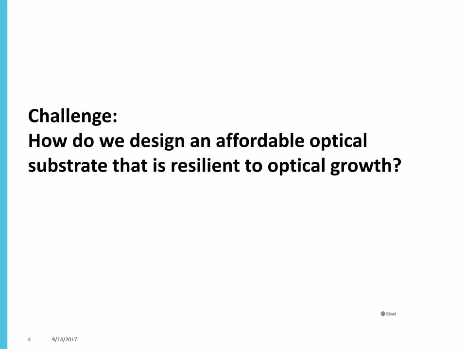
Challenge: How do we design an affordable optical substrate that is resilient to optical growth?
9/14/2017 4

Context
9/14/2017 5

ESnet is a dedicated mission network engineered to accelerate a broad range of science outcomes
We do this by offering unique capabilities, and optimizing the network for data acquisition, data
placement, data sharing, data mobility.
6 9/14/2017 imonga at es dot net

Mission: To Enable and Accelerate Scientific Discovery by Delivering Unparalleled Network Infrastructure, Capabilities, and Tools
7
Bulk Data Movement
Global Connectivity
• Potential network service requirements to support tomorrow’s scientific collaborations
Remote Control Applications
Deadline Scheduling Tele-Presence
Real Time Data Streaming
Network Content Caching
Network Security Services
Virtual Private Networks
Superfacility Model
Named Data Networking
Virtual Private Clouds
Application-Network Interaction
Distributed Workflow Integration

Next-generation network (ESnet6) drivers
– Exponential growth in network CAPACITY needs • 72% year-on-year traffic growth since 1990
• Cost effective solution to increase capacity as needed
–Network Life Cycle: Improve RELIABILITY • Replace aging infrastructure
• Increase the cyber-resiliency of the network
–Network FLEXIBILITY • Support increasingly complex workflow models
• Flexibility at all layers of the network is needed to support wide spectrum of science requirements
8

Design requirements
9
1. Capacity
• Predict usage
• Determine overheads (e.g. burst multiplier, resiliency requirements, short-term growth trends)
2. Services
• Document workflows
• Develop service portfolio*
*NB: Service Portfolio in conjunction with architecture design drives the technical requirements

Capacity Planning Process
10
1. Determine predicted baseline usage (for 2020, 2025, and 2030)
1. Perform best-fit growth curve of ingress traffic per router
2. Adjust individual router predictions such that total of all router ingress traffic matches ESnet’s 25+ year total traffic growth curve
3. Using historical flow data and predicted ingress traffic data, perform full mesh path computation to determine per link utilization from PE-to-PE
2. Strategic capacity planning* (for 2020 and 2025)
1. Add burst overhead bandwidth per link based on historical knowledge
2. Add additional bandwidth to paths based on resiliency strategy
3. Keep in view new projects on the horizon
*NB: This is an iterative process as we continue to monitor growth trends as well as field requests for new requirements (e.g. new experiments, etc)
11
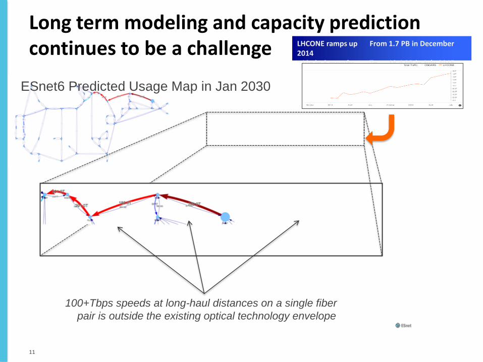
LHCONE ramps up From 1.7 PB in December 2014 ~10x in 8 months To 18.4 PB in July 2015
Long term modeling and capacity prediction continues to be a challenge
ESnet6 Predicted Usage Map in Jan 2030
100+Tbps speeds at long-haul distances on a single fiber
pair is outside the existing optical technology envelope
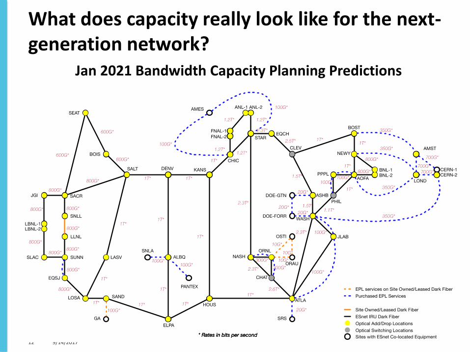
What does capacity really look like for the next-generation network? Jan 2021 Bandwidth Capacity Planning Predictions
9/14/2017 12

R&D Phase: Architecture and Technologies Matrix
13
Orchestrators
Layer 1
Layer 2
Layer 3
Alien Wave Optical Transport
P2P Optical Transport Systems
PKT-OTN Optical Transport Systems
Transport Router
DWDM
SDN Routers
SDN Switches
(B)
Packet
Transport
Router
Architecture
(F)
SDN Router
and OTS
Architecture
(C)
Router and
OTS
Architecture
(D)
Router and
PKT/OTN
OTS
Architecture
(E)
SDN Router
and
PKT/OTN
OTS
Architecture
(A)
Router and
DWDM
Ethernet
Switch
Architecture
DWDM Ethernet
Switches
Routers
Traditional Routed Packet Optical Integration Software Defined Networking

Orchestrators
Layer 1
Layer 2
Layer 3
Alien Wave Optical Transport
P2P Optical Transport Systems
PKT-OTN Optical Transport Systems
Transport Router
DWDM
SDN Routers
SDN Switches
(B)
Packet
Transport
Router
Architecture
(F)
SDN Router
and OTS
Architecture
(C)
Router and
OTS
Architecture
(D)
Router and
PKT/OTN
OTS
Architecture
(E)
SDN Router
and
PKT/OTN
OTS
Architecture
(A)
Router and
DWDM
Ethernet
Switch
Architecture
DWDM Ethernet
Switches
Routers
Optical Add/Drop mux (fixed-grid or flexgrid), with or without lambda switching, directionless or not
Foreign (alien) transponders Flexible transponders (or OTN-switch capable transponders)
Dark fiber Dark fiber Dark fiber Dark fiber Dark fiber Dark fiber Amplifiers Amplifiers Amplifiers Amplifiers Amplifiers Amplifiers
Packet switch fabrics
Investigating all possible options

Experimentation
9/14/2017 15

1. Packet-Optical integration – PTX 5000 (2015)
9/14/2017 16
http://www.juniper.net/us/en/local/pdf/whitepapers/2000552-en.pdf
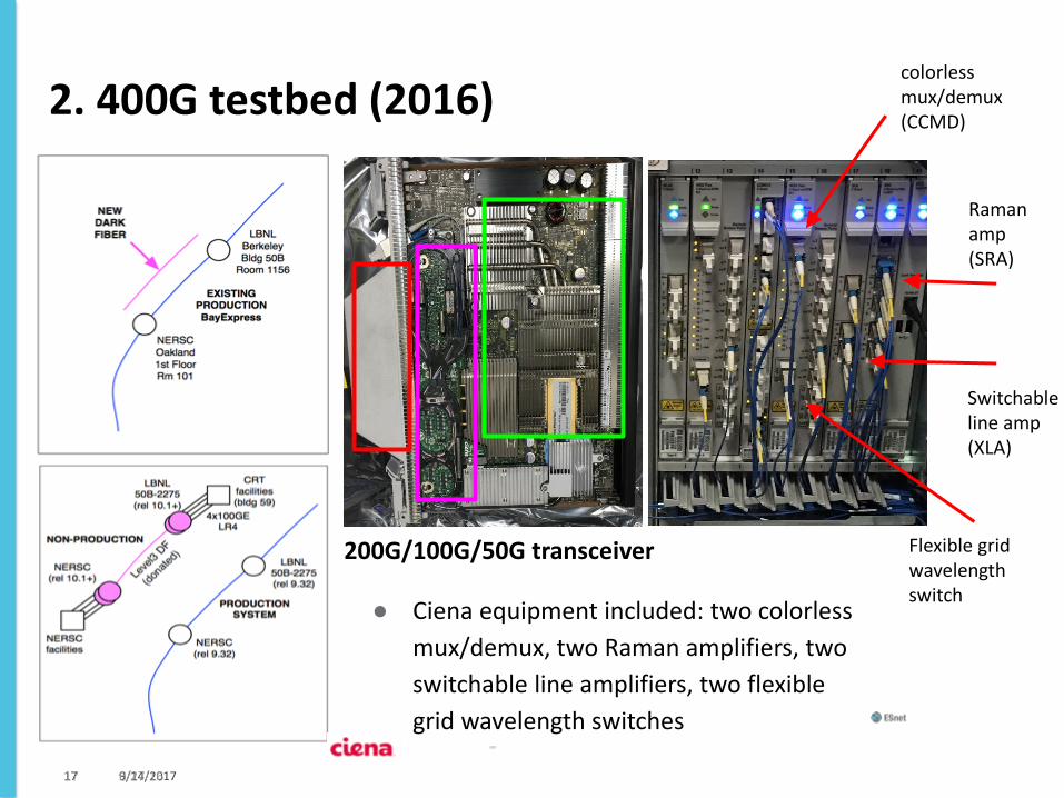
2. 400G testbed (2016)
9/14/2017 17
colorless mux/demux (CCMD)
Raman amp (SRA)
Switchable line amp (XLA)
Flexible grid wavelength switch
6/27/16 17
200G/100G/50G transceiver
● Ciena equipment included: two colorless
mux/demux, two Raman amplifiers, two
switchable line amplifiers, two flexible
grid wavelength switches

Testbed deployment over loaned fiber
6/27/16 18

Testbed deployment over loaned fiber: Spectrum Analysis
● Captured prior to super-channel configuration
● Shows channels
spaced 50 GHz apart
● Both channels running over the full 93.3 km fiber distance, error-free.
● Total spectrum
utilized for the 400G signal: 100 GHz
6/27/16 19

Testbed deployment over loaned fiber: Spectrum Analysis ● Captured after super-
channel configuration
● Shows channels spaced 37.5 GHz apart (black)
○ Increased spectral efficiency (bit/s/Hz)
● Both channels running
over the full 93.3 km fiber distance, error-free.
● Total spectrum utilized for
400G signal: 75 GHz Example impact on fiber capacity, given 4.4 THz of useable spectrum:
● 8.8 Tbps (88 100G @ 50 GHz) ● 11.7 Tbps (117 100G @ 37.5 GHz)
6/27/16 20

3. First Production 400G Service on ESnet5
Goal: Deploy and harden a 400G production
service (4x100 GigE), perform applications
testing, production run.
● Two new wavelengths were provisioned,
200G per wave (2x100 GigE payload)
● Wavelength Selectable Switches (WSSs)
are in the path, but are limited to 50 GHz
granularity.
● On BayExpress, the production 400G
circuit consumed 100 GHz of spectral
bandwidth
○ 2 adjacent 50 GHz channels
○ Comes as close to a “super channel”
as possible in production
6/27/16 21

Oakland Scientific Facility [1] Oakland, CA
Berkeley Lab’s Shyh Wang Hall [2] Berkeley, CA
6/27/16 22
400G
Direction of file system transfers, 15 PB moved between centers across 400G service
NERSC: File system Transfers

Thoughts
9/14/2017 23

Packet Optical
• No standard definition
• Is it:
– Integration of physical packet and optical functionality? Same chassis?
• Limiting and vendor lock-in
– Logical integration of packet and optical control plane? Same flow paradigm?
• G-MPLS vision? Transport SDN?
– Integration of services offered?
• MEF style Ethernet services
• Broadened our search from physically integrated products to abstract network
architecture (integration of forwarding, control and management plane)
9/14/2017 24

What is Disaggregation?
• Disaggregation is decoupling of software and hardware, and components inside as well
• Opposite of Monolithic
• Usually puts the responsibility of integrated system of disaggregated components on the buyer (in this case the network provider)
– Whether they do it themselves or pay someone to do it
• Pros
– Has the power to simplify – buy what you need
• Cons
– Specification and responsibility of the working system falls on the integrator/purchaser
9/14/2017 25
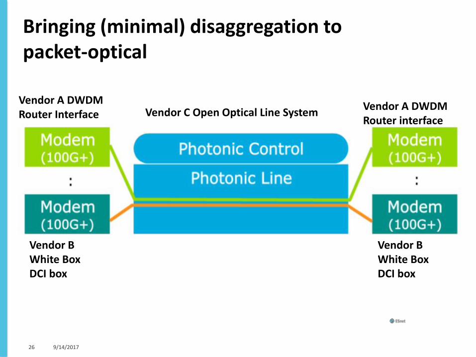
Bringing (minimal) disaggregation to packet-optical
9/14/2017 26
Vendor C Open Optical Line System Vendor A DWDM Router Interface
Vendor A DWDM Router interface
Vendor B White Box DCI box
Vendor B White Box DCI box

Pulling together a potential optical architecture
27
Open Line System
Packet Optical Integrated NEs
Segment Routing for TE
(Control Plane
disaggregation)
FlexGrid (to support >200Gbps waves)
Colorless support, no fixed filters
Directionless for wave provisioning
flexibility \
DWDM Optics
Dedicated transponder
shelf (White Box, DCI,
or Vendor integrated)

Considerations of future bandwidth needs
Scaling the optical layer involves: • The cost for additional channels (cost of transceivers pairs)
– underlying photonic layer allows use of the entire C-band – many unused photonic channels or paths still available in the network
• How far those channels can go (optical signal-to-noise ratio)
– determines the maximum reach from transmitter to receiver – consideration of Shannon limit, channel size, modulation format – higher modulations will be required for reaching higher fiber capacities
• The space, power and cooling required (port density, power efficiency)
– optimize for lowest Joules per bit – minimize optical-electrical conversions – besides transceiver cost, our next biggest concern
28
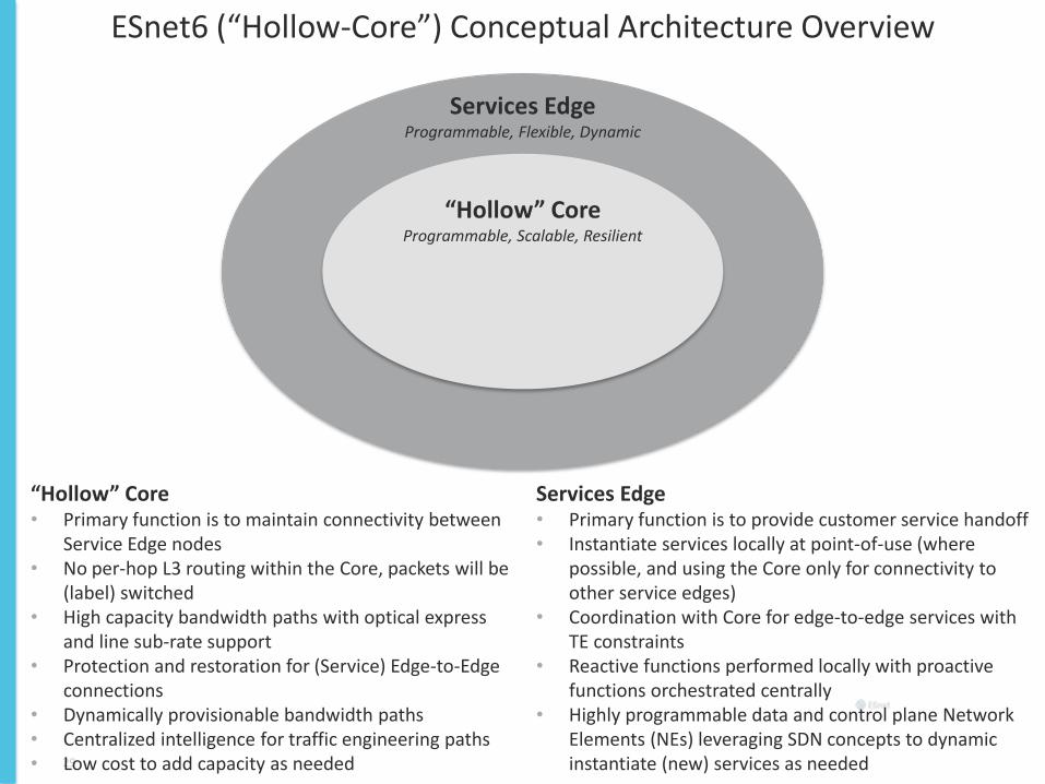
ESnet6 (“Hollow-Core”) Conceptual Architecture Overview
Services Edge • Primary function is to provide customer service handoff • Instantiate services locally at point-of-use (where
possible, and using the Core only for connectivity to other service edges)
• Coordination with Core for edge-to-edge services with TE constraints
• Reactive functions performed locally with proactive functions orchestrated centrally
• Highly programmable data and control plane Network Elements (NEs) leveraging SDN concepts to dynamic instantiate (new) services as needed
“Hollow” Core Programmable, Scalable, Resilient
29
Services Edge Programmable, Flexible, Dynamic
“Hollow” Core • Primary function is to maintain connectivity between
Service Edge nodes • No per-hop L3 routing within the Core, packets will be
(label) switched • High capacity bandwidth paths with optical express
and line sub-rate support • Protection and restoration for (Service) Edge-to-Edge
connections • Dynamically provisionable bandwidth paths • Centralized intelligence for traffic engineering paths • Low cost to add capacity as needed
Disaggregation, Open source, and Optical
9/14/2017 30

Combination of Packet-Optical, White Box and Disaggregation: Telecom Infra Project
9/14/2017 31

Combination of Packet-Optical, White Box and Disaggregation: Telecom Infra Project
9/14/2017 32

We have just started our journey…
9/14/2017 33

34
Thank You and Questions?