Compact Design of On-chip Elman Optical Recurrent Neural ...
for modern HFC networks
Optical Compact Receivers

HFCHFC 32
BKtel I Company portrait
Optical compact receiver ORA 9222-1G2 5
▪ Features and advantages 5
▪ Details 8
▪ Overview of options 10
Optical compact receiver ORA 9022-1G2 12
▪ Features and advantages 12
▪ Details 14
▪ Overview of options 16
Optical receiver modules 18
▪ ORD 9201-1G2, ORD 9202-1G2 18
Optical interfaces 18
▪ Version SC/APC, version E-2000 18
Components 19
▪ Overview 19
▪ WiFi module, monitoring transponder HMS 20
▪ Monitoring transponders DOCSIS, pluggable diplexers, zero cards 21
▪ Taps/splitters, optical components 22
Optical micro-nodes for RFoG 24
Block diagrams 25
Technical data 27
Order number overview 35
Our Company
The BKtel Group has its origin in the
foundation of BKtel communications in
1997. The group was extended in 2002
with BKtel systems (merged with BKtel
communications in 2009), BKtel
components (2006), BKtel Photonics
(2014) and BKtel networks in 2017.
Further international offices were founded
in China and Japan for the growing Asian
market. The entire group has currently a
workforce of over 130 employees
worldwide, based in Germany in Hueckel-
hoven, (near Düsseldorf), in Rosenheim
(near Munich) and in Kornwestheim (near
Stuttgart).
The company develops and manufactures
products in the field of interactive FTTH-,
Video Overlay-, RFoG- and HFC-
networks for high performance data,
telephone and cable TV services.
The high quality products as well as the
comprehensive support in designing
optical networks make BKtel to one of the
leading suppliers in the FTTH and HFC
market.
Our Products
BKtel develops equipment and software
for FTTH and HFC broadband networks.
The product portfolio includes a wide
range of products starting from equipment
for optical transmission such as optical
transmitters, amplifiers, and receivers and
customer premises equipment, CATV
headends, coaxial cable amplifiers. BKtel
manufacturing facilities guarantee a high
quality standard (ISO 9001 certified).
Furthermore the company offers a
complete range of services such as
planning, installation and training.

HFCHFC 54
FeATuRes
▪ Higher accuracy over the
entire level range
▪ Extended pilot range:
82.5 MHz ... 450 MHz for
the lower pilot/
420 MHz ... 998 MHz for
the upper pilot
▪ Reads the remote feed volt-
age, the remote feed current
per port, the channel level
of the forward signal path
(“channel scan”) via the
monitoring
▪ Modular FttC fibre node
with new flexible design
▪ Double receiver and single
return path transmitter
with constant light control
permit full redundancy and
segmentation
▪ Automatic switchover facility
in the event of interruption
▪ Highly-efficient power factor
correction (power factor
close to 1)
▪ GaN technology end stages
▪ Electronic settings via Web
browser with mobile devices
by WiFi module
Features
▪ One to four active high-level outputs (trunk/distribution, two separate end stages)
▪ Full redundancy operation available in forwards and return path
▪ Segmentation available in the downstream and upstream
▪ One or two single or twin optical pluggable receiver modules (1 ... 4 receivers)
▪ One or two plug-in return path transmitters for segmentation, coupling or redun-
dancy, see OSR 900x
▪ Electronically settable matrix in the forwards path and return path
▪ Innovative operating concept: Electronic actuators, setting via a hand-held operating
device or Web browser
▪ Automatic levelling in the forwards path
▪ Extremely low-noise receiver
▪ Internal optical interfaces and fibre management for unrestricted outdoor use
(protection class: IP 67)
▪ Optional CWDM filters or splitters can be integrated
▪ Plug-in diplex filters 65/85 MHz, 85/105 MHz or 204/258 MHz
▪ “Plug-and-Play” by combination of two control loops
• Two-pilot control for level and slope
• Optical constant light control
▪ Monitoring by HMS or DOCSIS transponder
▪ Creates fibre identification code in the return path transmitters
▪ Output level up to 119 dBµV per output (for two outputs)
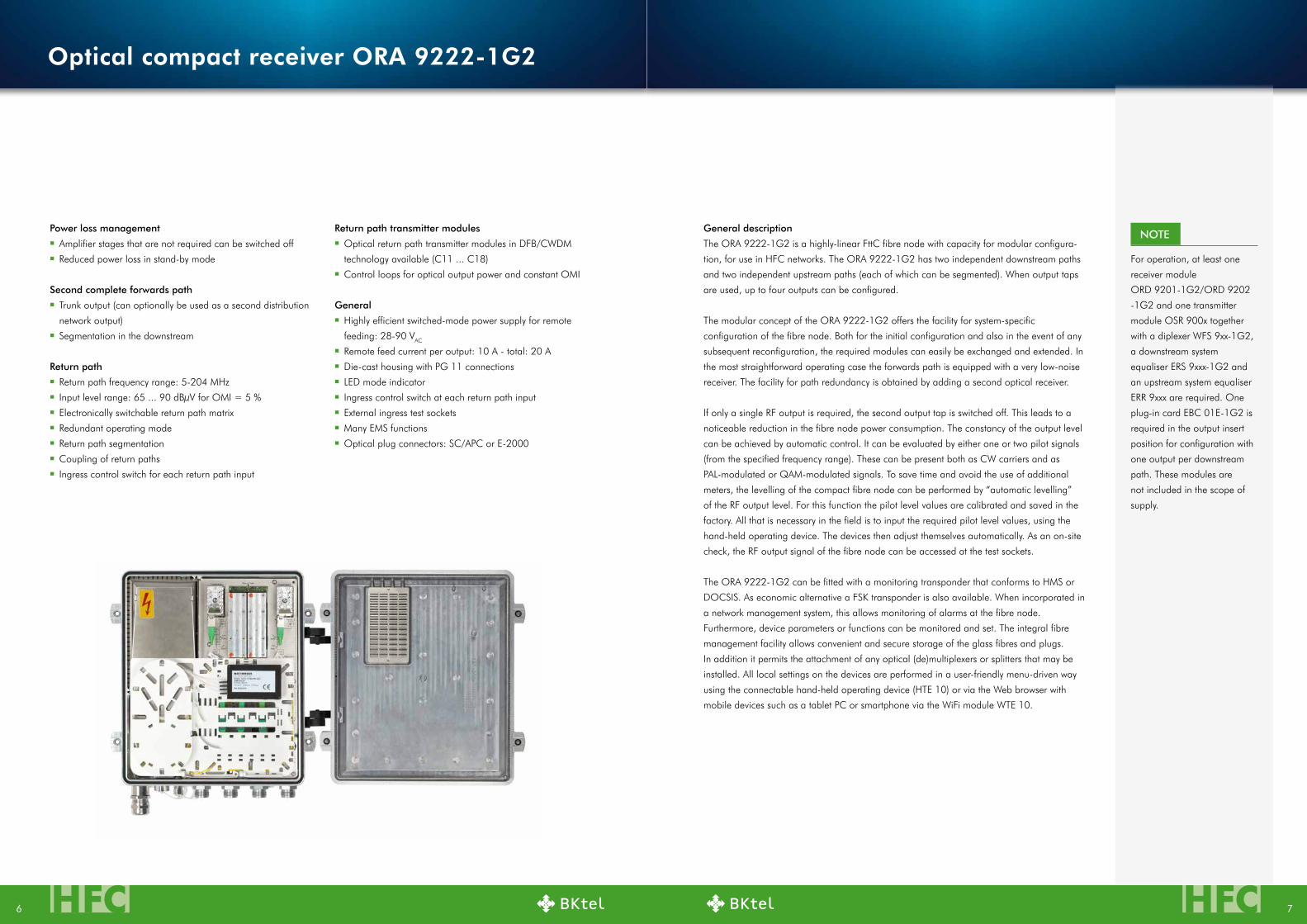
Optical compact receiver ORA 9222-1G2
Optical compact receivers
NeW1.2 GHz
Major events cast a shadow ahead of them. The new DOCSIS 3.1 standard provides for signifi-
cantly higher data transmission capacity in HFC networks. As well as efficient error correction and
extended modulation profiles, the use of a wider frequency range up to 1.2 GHz also creates more
bandwidth.
The new “1G2” optical compact receivers allow network operators to benefit in full from these
advantages. They are designed for frequency ranges up to 1218 MHz in the forward path and up
to 204 MHz in the return path, but can also be used without restriction in existing networks. The
electronic frequency range changeover and particularly high output levels allow network upgrades
to be implemented step-by-step without problems.
Like all other optical compact receivers from BKtel, DOCSIS 3.1 operation can of course be
implemented immediately in the available frequency ranges. Outstanding intermodulation
parameters and the lowest noise levels in comparison with its competitors ensure the best possible
system characteristics.
Features and advantagesScalable optical compact receivers with four outputs
Overview Optical compact receiver ORA 9222-1G2
HFCHFC 76
Power loss management
▪ Amplifier stages that are not required can be switched off
▪ Reduced power loss in stand-by mode
Return path transmitter modules
▪ Optical return path transmitter modules in DFB/CWDM
technology available (C11 ... C18)
▪ Control loops for optical output power and constant OMI
General
▪ Highly efficient switched-mode power supply for remote
feeding: 28-90 VAC
▪ Remote feed current per output: 10 A - total: 20 A
▪ Die-cast housing with PG 11 connections
▪ LED mode indicator
▪ Ingress control switch at each return path input
▪ External ingress test sockets
▪ Many EMS functions
▪ Optical plug connectors: SC/APC or E-2000
Return path
▪ Return path frequency range: 5-204 MHz
▪ Input level range: 65 ... 90 dBµV for OMI = 5 %
▪ Electronically switchable return path matrix
▪ Redundant operating mode
▪ Return path segmentation
▪ Coupling of return paths
▪ Ingress control switch for each return path input
second complete forwards path
▪ Trunk output (can optionally be used as a second distribution
network output)
▪ Segmentation in the downstream
General description
The ORA 9222-1G2 is a highly-linear FttC fibre node with capacity for modular configura-
tion, for use in HFC networks. The ORA 9222-1G2 has two independent downstream paths
and two independent upstream paths (each of which can be segmented). When output taps
are used, up to four outputs can be configured.
The modular concept of the ORA 9222-1G2 offers the facility for system-specific
configuration of the fibre node. Both for the initial configuration and also in the event of any
subsequent reconfiguration, the required modules can easily be exchanged and extended. In
the most straightforward operating case the forwards path is equipped with a very low-noise
receiver. The facility for path redundancy is obtained by adding a second optical receiver.
If only a single RF output is required, the second output tap is switched off. This leads to a
noticeable reduction in the fibre node power consumption. The constancy of the output level
can be achieved by automatic control. It can be evaluated by either one or two pilot signals
(from the specified frequency range). These can be present both as CW carriers and as
PAL-modulated or QAM-modulated signals. To save time and avoid the use of additional
meters, the levelling of the compact fibre node can be performed by “automatic levelling”
of the RF output level. For this function the pilot level values are calibrated and saved in the
factory. All that is necessary in the field is to input the required pilot level values, using the
hand-held operating device. The devices then adjust themselves automatically. As an on-site
check, the RF output signal of the fibre node can be accessed at the test sockets.
The ORA 9222-1G2 can be fitted with a monitoring transponder that conforms to HMS or
DOCSIS. As economic alternative a FSK transponder is also available. When incorporated in
a network management system, this allows monitoring of alarms at the fibre node.
Furthermore, device parameters or functions can be monitored and set. The integral fibre
management facility allows convenient and secure storage of the glass fibres and plugs.
In addition it permits the attachment of any optical (de)multiplexers or splitters that may be
installed. All local settings on the devices are performed in a user-friendly menu-driven way
using the connectable hand-held operating device (HTE 10) or via the Web browser with
mobile devices such as a tablet PC or smartphone via the WiFi module WTE 10.
NOTe
For operation, at least one
receiver module
ORD 9201-1G2/ORD 9202
-1G2 and one transmitter
module OSR 900x together
with a diplexer WFS 9xx-1G2,
a downstream system
equaliser ERS 9xxx-1G2 and
an upstream system equaliser
ERR 9xxx are required. One
plug-in card EBC 01E-1G2 is
required in the output insert
position for configuration with
one output per downstream
path. These modules are
not included in the scope of
supply.
Optical compact receiver ORA 9222-1G2
HFCHFC 98
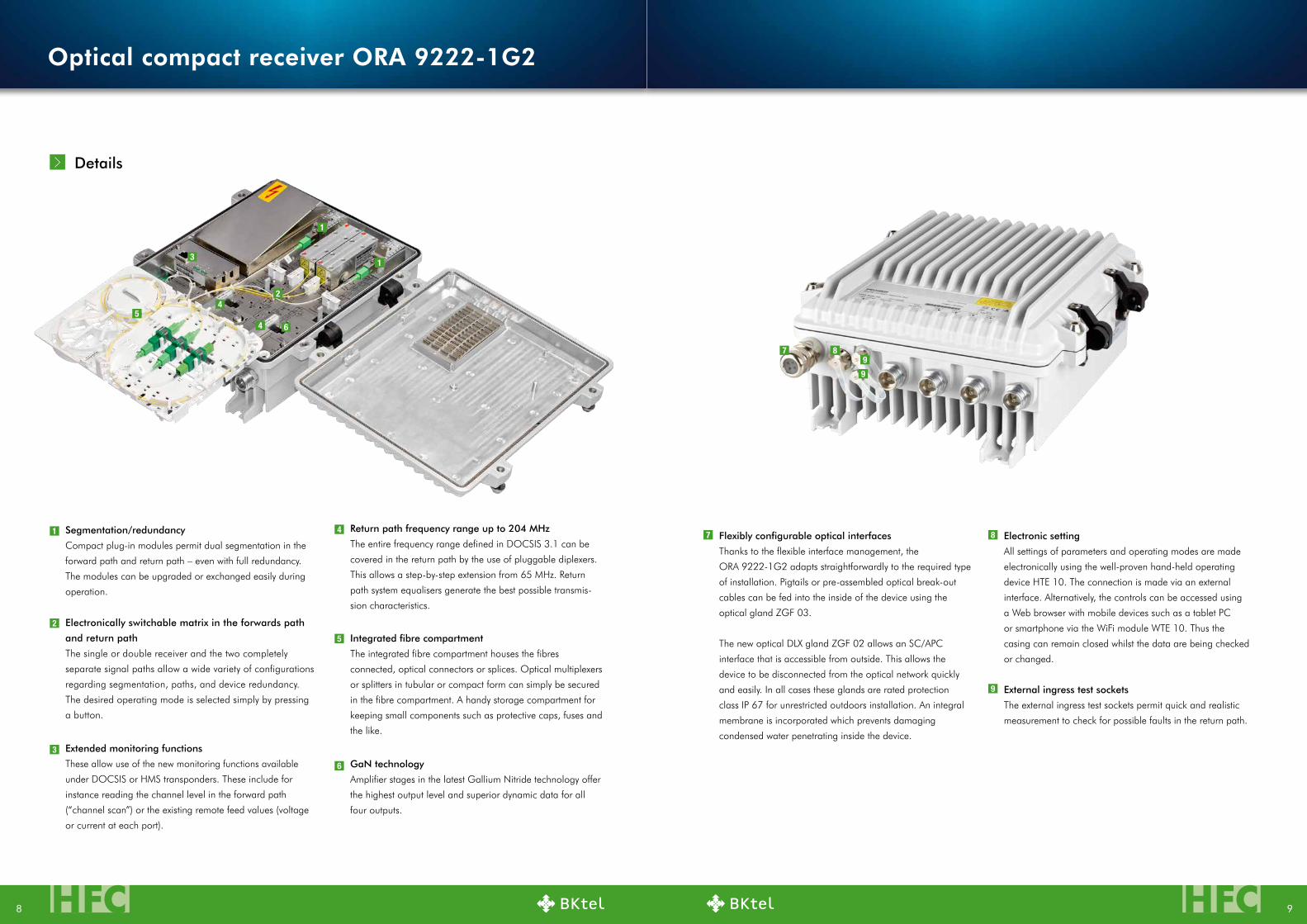
segmentation/redundancy
Compact plug-in modules permit dual segmentation in the
forward path and return path – even with full redundancy.
The modules can be upgraded or exchanged easily during
operation.
GaN technology
Amplifier stages in the latest Gallium Nitride technology offer
the highest output level and superior dynamic data for all
four outputs.
extended monitoring functions
These allow use of the new monitoring functions available
under DOCSIS or HMS transponders. These include for
instance reading the channel level in the forward path
(“channel scan”) or the existing remote feed values (voltage
or current at each port).
Return path frequency range up to 204 MHz
The entire frequency range defined in DOCSIS 3.1 can be
covered in the return path by the use of pluggable diplexers.
This allows a step-by-step extension from 65 MHz. Return
path system equalisers generate the best possible transmis-
sion characteristics.
electronically switchable matrix in the forwards path
and return path
The single or double receiver and the two completely
separate signal paths allow a wide variety of configurations
regarding segmentation, paths, and device redundancy.
The desired operating mode is selected simply by pressing
a button.
Flexibly configurable optical interfaces
Thanks to the flexible interface management, the
ORA 9222-1G2 adapts straightforwardly to the required type
of installation. Pigtails or pre-assembled optical break-out
cables can be fed into the inside of the device using the
optical gland ZGF 03.
The new optical DLX gland ZGF 02 allows an SC/APC
interface that is accessible from outside. This allows the
device to be disconnected from the optical network quickly
and easily. In all cases these glands are rated protection
class IP 67 for unrestricted outdoors installation. An integral
membrane is incorporated which prevents damaging
condensed water penetrating inside the device.
Integrated fibre compartment
The integrated fibre compartment houses the fibres
connected, optical connectors or splices. Optical multiplexers
or splitters in tubular or compact form can simply be secured
in the fibre compartment. A handy storage compartment for
keeping small components such as protective caps, fuses and
the like.
electronic setting
All settings of parameters and operating modes are made
electronically using the well-proven hand-held operating
device HTE 10. The connection is made via an external
interface. Alternatively, the controls can be accessed using
a Web browser with mobile devices such as a tablet PC
or smartphone via the WiFi module WTE 10. Thus the
casing can remain closed whilst the data are being checked
or changed.
external ingress test sockets
The external ingress test sockets permit quick and realistic
measurement to check for possible faults in the return path.
1
1
1
2
2
3
3
4
4
4
5
5
6
6
7
7
8
8
9
9
9
Details
Optical compact receiver ORA 9222-1G2

HFCHFC 1110
Monitoring transponder
Available fittings:
TVM 850/H, TVM 1000, TVM 500
Optical receiver modules
(two insert positions)
Available fittings:
ORD 9201-1G2, ORD 9202-1G2
Compartment for fibres, pigtails,
patch cables
Available patch cables for
device-internal connections:
OFC 90/SC, OFC 90/SC-E
Diplexer
Available fittings:
WFS 906-1G2, WFS 908-1G2,
WFS 920-1G2
Output splitter field
(two insert positions)
Available fittings for operation with
one or two outputs:
EBC 01E-1G2
Operation with three or four outputs:
EBC 90-1G2, EAC 90-1G2,
EAC 93-1G2, EAC 94-1G2
Optical return path transmitters
(two insert positions)
Available fittings:
OSR 9003, OSR 9003-P65-Cxx
Bracket for optical
couplings
Available fittings:
OKU 01/SC-E, OKU 01/SC, OKU 01/E
upstream system equaliser
(Low-pass)
Available fittings:
ERR 9065, ERR 9085, ERR 9204
Downstream system equaliser
(High-pass)
Available fittings:
ERS 9085-1G2, ERS 9105-1G2,
ERS 9258-1G2
Bracket for optical components in
tubular design or splices
Fibre entry
Available fittings: ZGF 03, ZGF 02
electronic setting
Via hand-held operating device: HTE 10
Via Web browser with mobile devices by WiFi module: WTE 10
universal insert position
(one insert position per forwards path)
Available fittings:
System equaliser on request
RF interfaces
Available fittings: PG-11 glands or cable fittings
Bracket for optical multiplexers in compact form1
1 1
2 2
3
3 3
4
4 4
5
5
6
6 6
7
7
8
9
1
1
2
2
3
3
4
4
9 9
11
11
10
10
8 8
Fibre compartment open Fibre compartment closed
Overview of options
Optical compact receiver ORA 9222-1G2

HFCHFC 1312
Top functionality
The optical compact receiver ORA 9022-1G2 from BKtel com-
bines previously unequalled functionality with excellent technical
data at an excellent price-performance ratio.
An integrated, double-sided fibre compartment houses the fibres
and optical connectors. Practical detail: There is also space for
tubular or compact optical splitters or WDM couplers. They are
then protected and a separate splice housing is unnecessary. This
concept is also advantageous during installation: The optical
receiver can be completely pre-assembled. During installation in
the field it is only necessary to make the fibre connections.
Features
▪ Frequency range 1006/1218 MHz switchable
▪ Increased output level for operation at 1218 MHz
▪ Modular FTTC fibre node
▪ Internal optical interfaces for unrestricted usage outdoors (protection class IP 54)
▪ Optical interfaces also optionally available on the device for external connections
▪ Innovative operating concept:
• Electronic actuators, setting via WiFi module WTE 10
▪ Electronically settable matrix in the return path:
• Redundant operation
• Return path segmentation
• Automatic switching available in the event of an interruption
▪ Optional WDM coupler or splitter can be integrated
▪ Latest GaN-MMIC technology
▪ Single or twin optical pluggable receiver module
▪ Fully redundant operation available in the forward and return path
▪ Output level up to 121 dBµV
▪ One, two or three trunk/high-level outputs (two separate end stages)
▪ “Plug-and-Play” by combination of AGC and ALSC (two pilot signals)
▪ Automatic levelling in the forward path
▪ Extremely low-noise receiver (best in class)
▪ One or two plug-in return path transmitters for segmentation or redundancy,
see OSR 900x
▪ Optical return path transmitter modules in DFB/CWDM technology available
▪ Permits easy exchange of modules
▪ Highly efficient switch-mode power supply with power factor correction
▪ Die-cast housing with PG 11 connections
▪ LED mode indicator
▪ Plug-in diplex filters 65/85 MHz, 85/105 MHz, 204/258 MHz
▪ Ingress control switch at each return path input
▪ Ingress test socket for each return path input (externally accessible),
can optionally be used as a broadband input
▪ Many EMS functions
▪ Optical plug connectors: SC/APC or E-2000
▪ Higher accuracy over the
entire level range
▪ Extended pilot range:
82.5 MHz ... 450 MHz for
the lower pilot/
420 MHz ... 998 MHz for
the upper pilot
▪ Read the remote feed
voltage via the monitoring
▪ Electronic settings via Web
browser with mobile devices
by WiFi module
(tablet PC, smartphones,
notebooks etc.)
▪ Highly-efficient power factor
correction (power factor
close to 1)
Variable return path management
The electronically switchable return path matrix is of particular
interest for step-by-step network expansion. The two return path
inputs are independent due to the use of separate diplex filters,
and their connections to the two return path transmitters can vary
from each other. For instance, both return paths can initially be
coupled to a common transmitter. As data traffic increases, a
second return path transmitter can be fitted and each of the two
return paths connected to its own dedicated transmitter.
An externally accessible ingress test socket is available for each
of the return paths, so measurements can be performed quickly.
The signal flow direction on these test sockets can be switched
from “measure” to “inject” so that signals can be injected into
the return paths. This function can also be used for broadband
return path inputs up to 204 MHz.
The optical compact receiver ORA 9022-1G2 from BKtel is
suitable for all cable network operators with HFC networks. Due
to the step-by-step segmentation features, the plug-in modules
and the integrated fibre compartment, it provides the flexibility for
optimally adapting HFC networks to the specific requirements.
Fully redundant operation
The device can be equipped electro-optically with plug-in
modules for forward receivers or return path transmitters. Up to
two modules in each case provide fully redundant operation.
The modules are easy to exchange.
Various DFB types in 1310 nm and CWDM technology are
available as return path transmitters. Thanks to the high output
power of up to +6 dBm, very large distances can be covered.
As a result it is possible to design optical fibre networks without
intermediate hubs, saving fibre.
“Plug-and-Play” redefined
All device settings are made electronically using the hand-held
operating device HTE 10 or via the WiFi module WTE 10 by Web
browser using mobile devices such as a tablet PC, smartphone
etc. This feature not only saves plug-in cards, but also simplifies
setup. During automatic levelling the operator only needs to
define the required output level and slope. At the press of a
button the device then automatically sets optimal dynamic data.
The copy function can copy all settings and transfer them to other
devices: setup could hardly be quicker. The integrated constant
2-pilot and constant light controls ensure a frequency-agile
output level.
FeATuRes
Optical compact receiver ORA 9022-1G2
Features and advantagesScalable optical compact receivers with three outputs
Optical compact receiver ORA 9022-1G2
NeW1.2 GHz
HFCHFC 1514
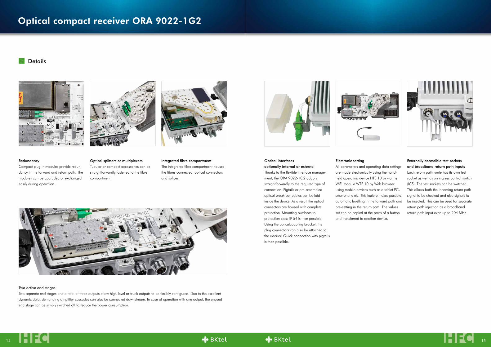
externally accessible test sockets
and broadband return path inputs
Each return path route has its own test
socket as well as an ingress control switch
(ICS). The test sockets can be switched.
This allows both the incoming return path
signal to be checked and also signals to
be injected. This can be used for separate
return path injection as a broadband
return path input even up to 204 MHz.
Redundancy
Compact plug-in modules provide redun-
dancy in the forward and return path. The
modules can be upgraded or exchanged
easily during operation.
Integrated fibre compartment
The integrated fibre compartment houses
the fibres connected, optical connectors
and splices.
Optical splitters or multiplexers
Tubular or compact accessories can be
straightforwardly fastened to the fibre
compartment.
Optical interfaces
optionally internal or external
Thanks to the flexible interface manage-
ment, the ORA 9022-1G2 adapts
straightforwardly to the required type of
connection. Pigtails or pre-assembled
optical break-out cables can be laid
inside the device. As a result the optical
connectors are housed with complete
protection. Mounting outdoors to
protection class IP 54 is then possible.
Using the opticalcoupling bracket, the
plug connectors can also be attached to
the exterior. Quick connection with pigtails
is then possible.
electronic setting
All parameters and operating data settings
are made electronically using the hand-
held operating device HTE 10 or via the
WiFi module WTE 10 by Web browser
using mobile devices such as a tablet PC,
smartphone etc. This feature makes possible
automatic levelling in the forward path and
pre-setting in the return path. The values
set can be copied at the press of a button
and transferred to another device.
Two active end stages
Two separate end stages and a total of three outputs allow high-level or trunk outputs to be flexibly configured. Due to the excellent
dynamic data, demanding amplifier cascades can also be connected downstream. In case of operation with one output, the unused
end stage can be simply switched off to reduce the power consumption.
Details
Optical compact receiver ORA 9022-1G2

HFCHFC 1716
Optical receiver modules
Available fittings:
ORD 9201-1G2, ORD 9202-1G2
Monitoring transponder
Available fittings:
TVM 850/H, TVM 1000, TVM 500
electronically switchable
return path matrix
universal insert position
Insert position which can take an equal-
iser if required; fitted as standard with a
zero jumper.
Available fittings:
System equaliser on request
Fibre entry
Two variants are possible:
▪ Insertion of optical break-out cables
or pigtails via a PG screw-type
gland (included in delivery)
▪ Optical coupling bracket: ZOH 04
electronic setting
Via hand-held operating device: HTE 10
Via Web browser with mobile
devices by WiFi module: WTE 10
Bracket for optical components in
tubular design or splices
Available fittings:
BWMR 1310/1550, BWMR 1310
Output splitter field
Available fittings:
EBC 01E-1G2, EBC 90-1G2,
EAC 90-1G2, EAC 93-1G2,
EAC 94-1G2
RF interfaces
Available fittings: PG-11 glands or
cable fittings Compartment for fibres, pigtails,
patch cables
Suitable patch cables for device-inter-
nal connections:
OFC 90/SC, OFC 90/SC-E
Bracket for optical couplings
Available fittings:
OKU 01 SC, OKU 01 SC-E,
OKU 01 E
Up to six optical couplings OKU 01
SC and/or OKU 01 E or up to four
OKU 01 SC-E can be used.
Optical return path transmitters
(two insert positions)
Available fittings:
OSR 9003, OSR 9003 P65-Cxx
1 7
8
9
10
11
12
13
2
3
4
5
6
Diplexer
Available fittings:
WFS 906-1G2, WFS 908-1G2,
WFS 920-1G2
Overview of options
88
4
1
7
9
10
1213
11
2
3
5
Optical compact receiver ORA 9022-1G2

HFCHFC 1918
Version sC/APC
Version e-2000
Optical receiver module
ORD 9201-1G2/9202-1G2:
Device interface SC/APC, transition to
E-2000 with patch cable
OFC 90/SC and optical coupling
OKU 01 SC-E (or OFC 90/SC-E and
OKU 01 E)
Optical receiver module
ORD 9201-1G2/9202-1G2:
Device interface SC/APC, pigtail or
cable can be plugged in directly
Optical return path transmitters
OsR 900x:
Pigtail device interface with SC/APC,
connection of the pigtail or cable using
optical coupling OKU 01/SC
Optical return path transmitters
OsR 900x:
Device interface pigtail with SC/APC,
transition to E-2000 with optical cou-
pling OKU 01 SC-E
Optical interfaces
1 2
3 4
Optical receiver modules
Note
For operation of the
ORA 9222-1G2 or
ORA 9022-1G2, at least one
ORD 9201-1G2 or
ORD 9202-1G2 plug-in
module is necessary
The optical receiver modules ORD 9201-1G2 and ORD 9202-1G2 are intended for
use in the optical fibre node ORA 9222-1G2 or ORA 9022-1G2. The ORD 9201-1G2
is a single receiver module and provides one optical receiver for each RF path. The
ORD 9202-1G2 is a twin module and for redundancy purposes provides two optical
receivers for each RF path. ORD 9202-1G2
Features
▪ Optical receiver modules
▪ Optical reception of CATV frequency multiplex signals from a single monomode glass
fibre
▪ Extremely low-noise receiver (best in class)
▪ Optical plug connectors: SC/APC
▪ For operation with ORA 9222-1G2 or ORA 9022-1G2
ORD 9201-1G2, ORD 9202-1G2
Components
Overview
Description Type Order no.ORA
9222-1G2ORA
9022-1G2
Zero card for operation with one output 1.2 GHz EBC 00-1G2 24510217
Splitter (two symmetrical outputs) 1.2 GHz EBC 90-1G2 24510214
Tap (3/6 dB) 1.2 GHz EAC 93-1G2 24510216
Tap (1.5/10 dB) 1.2 GHz EAC 90-1G2 24510215
Tap (0.8/20 dB) 1.2 GHz EAC 94-1G2 24510220
HMS monitoring transponder (5-42 MHz), frequency-agile TVM 850/H 26210077
DOCSIS monitoring transponder TVM 1000 26210086
FSK moitoring transponder TVM 500 26210846
WiFi module for wireless manual operation via a Web browser WTE 10 25010086
Adapter ring PG 11 to ⅝" EMU 29 273243
Adapter PG 11 to 3.5/12 socket EMP 53 25010011
PG 11 to IEC connector (f) with M14 male thread EMP 34 275289
PG 11 to F socket (female) EMP 35 275300
Plug-in diplexers (device assignment overview)
The table shows the number of plug-in modules for full configuration of each device.
Type Order no. ORA 9222-1G2 ORA 9022-1G
WFS 906-1G2 24510218 2
WFS 908-1G2 24510222 2
WFS 920-1G2 24510209 2
ERR 9065 24510156 2
ERR 9085 24510158 2
ERR 9204 24510211 2
ERS 9085-1G2 24510219 2 1
ERS 9105-1G2 24510223 2 1
ERS 9258-1G2 24510210 2 1
1
2
3
4
Optical receiver modules, optical interfaces Components
HFCHFC 2120
Monitoring transponder DOCsIs/euroDOCsIs 2.0, frequency-agileTVM 1000
▪ Monitoring transponder for amplifiers and optical compact receivers
(see table on page 31)
▪ Monitoring of various parameters such as voltage, current consumption, internal
temperature, etc.
▪ Transmission within DOCSIS or EuroDOCSIS protocol
▪ 10/100 BaseT service interface
▪ Frequency-agile in the range 5-65/90-862 MHz
▪ Additional monitoring functions
Plug-in diplexersWFS 906-1G2, ERS 9085-1G2, ERR 9065 WFS 908-1G2, ERS 9105-1G2, ERR 9085 WFS 920-1G2, ERS 9258-1G2, ERR 9204
Diplexers and return path system equalisers for improving the return path band limits.
Components for frequency range 65/85 MHz
▪ WFS 906-1G2: Input and output diplexer 65/85 MHz
▪ ERS 9085-1G2: Interstage downstream equaliser (downstream from 85 MHz)
▪ ERR 9065 Return path system equaliser (upstream up to 65 MHz)
Components for frequency range 85/105 MHz
▪ WFS 908-1G2: Input and output diplexer 85/105MHz
▪ ERS 9105-1G2: Interstage downstream equaliser (downstream from 105 MHz)
▪ ERR 9085: Return path system equaliser (upstream up to 85 MHz)
Components for frequency range 204/258 MHz
▪ WFS 920-1G2: Input and output diplexer 204/258MHz
▪ ERS 9258-1G2: Interstage downstream equaliser (downstream from 258 MHz)
▪ ERR 9204: Return path system equaliser (upstream up to 204 MHz)
Monitoring transponder HMsTVM 850/H
▪ Monitoring transponder for compact and house connection amplifiers and also
optical compact receivers (see table on page 31)
▪ Monitoring of various parameters such as voltage, current consumption, internal
temperature, etc.
▪ Control of the ingress control switch in devices that are equipped with this facility
▪ Transmission by the HMS protocol
▪ Frequency-agile in the range 5-42 MHz
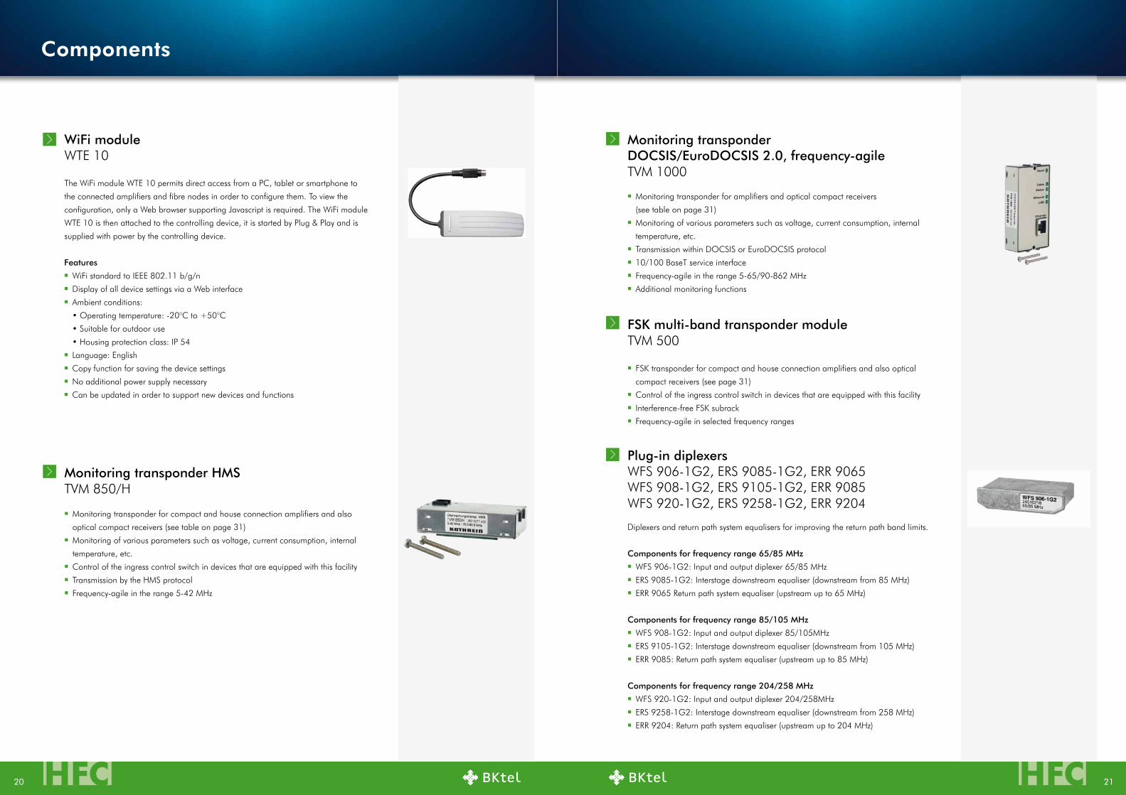
WiFi moduleWTE 10
The WiFi module WTE 10 permits direct access from a PC, tablet or smartphone to
the connected amplifiers and fibre nodes in order to configure them. To view the
configuration, only a Web browser supporting Javascript is required. The WiFi module
WTE 10 is then attached to the controlling device, it is started by Plug & Play and is
supplied with power by the controlling device.
Features
▪ WiFi standard to IEEE 802.11 b/g/n
▪ Display of all device settings via a Web interface
▪ Ambient conditions:
•Operatingtemperature:-20°Cto+50°C
•Suitableforoutdooruse
•Housingprotectionclass:IP54
▪ Language: English
▪ Copy function for saving the device settings
▪ No additional power supply necessary
▪ Can be updated in order to support new devices and functions
Components
FsK multi-band transponder moduleTVM 500
▪ FSK transponder for compact and house connection amplifiers and also optical
compact receivers (see page 31)
▪ Control of the ingress control switch in devices that are equipped with this facility
▪ Interference-free FSK subrack
▪ Frequency-agile in selected frequency ranges

HFCHFC 2322
Optical couplingsOKU 01/SC, OKU 01/SC-E, OKU 01/E
▪ Optical couplings for universal use
▪ Available types:
• OKU 01/SC: Double-sided SC/APC
• OKU 01/SC-E: Optical adapter couplings from SC/APC to E-2000
• OKU 01/E: Double-sided E-2000
Optical coupling bracket (only ORA 9022-1G2)ZOH 04
▪ For external optical plug connectors
▪ The optical patch cable OFC 90/SC may be necessary for connection
Optical return path transmittersOSR 9003 modules
▪ Optical return path transmitter modules for use in the ORA 9222-1G2 and
ORA 9022-1G2
▪ Electro-optical conversion of the return path signals
▪ DFB laser with optical isolator
▪ Optical output power: +6 dBm or +3 dBm
▪ Choice of eight different CWDM wavelengths, others on request
Available types:
OSR 9003 +3/+6 dBm | 1310 nm | 24610201
OSR 9003 P65-C11 +3/+6 dBm | 1471 nm | 24610424
OSR 9003 P65-C12 +3/+6 dBm | 1491 nm | 24610425
OSR 9003 P65-C13 +3/+6 dBm | 1511 nm | 24610426
OSR 9003 P65-C14 +3/+6 dBm | 1531 nm | 24610427
OSR 9003 P65-C15 +3/+6 dBm | 1551 nm | 24610385
OSR 9003 P65-C16 +3/+6 dBm | 1571 nm | 24610428
OSR 9003 P65-C17 +3/+6 dBm | 1591 nm | 24610429
OSR 9003 P65-C18 +3/+6 dBm | 1611 nm | 24610430
Taps/splittersEAC 90-1G2, EAC 93-1G2, EAC 94-1G2, EBC 90-1G2
Optical glandsZGF 02, ZGF 03
The purpose of the gland ZGF 03 is to allow optical cables (pigtails) to pass through
into the inside of the amplifier point casing. The gland ZGF 02 contains an SC/APC
coupling and permits connection of a single-fibre WDM system. ZGF 02 and 03 are
suitable for ORA 9222-1G2.
▪ The purpose of the gland ZGF 03 is to allow optical cables (pigtails) to pass through
into the inside of the amplifier point casing
▪ Up to four optical cables with a diameter of max. 4 mm each can be fed through
▪ The gland ZGF 02 contains an SC/APC coupling and permits connection of a
single-fibre WDM system
▪ Installation is performed at a free cable opening (PG 11) in the amplifier casing
▪ Degree of protection when correctly installed: IP 67 (ZGF 02/03)
ZGF 02
Optical multiplexer/ demultiplexer, tubular designBWMR 1310/1550, BWMR 1310
▪ Optical multiplexer/demultiplexer:
• Wavelengths: 1310/1550 nm, 1310/CWDM C05 C18
• Application: for instance separation of forwards/return path
▪ High reliability
▪ High isolation
▪ Low insertion loss
▪ Optical connections: 900 µm fibres, plug connectors SC/APC
Optical patch cablesOFC 90/SC, OFC 90/SC-E
▪ Optical patch cables for universal use
▪ Available types:
• OFC90/SC:Double-sidedSC/APC8°
• OFC90/SC-E:OneplugSC/APC8°,oneplugE-20008°
Components
Zero cardsEBC 01E-1G2, EBC 00-1G2
▪ Plug-in modules for operation with an input or output
▪ EBC 01E-1G2: For operation in the output insert positions (for ORA 9222-1G2)
▪ EBC 00-1G2: For operation in the output insert position (for ORA 9022-1G2)

HFCHFC 2524
ORA 118D-RFoG
The micro-nodes ORA 11xD-RFoG are intended for use in FttB and FttH networks. For RFoG
the return path laser is switched on only if data are actually being transmitted on this return
path by a cable modem.
This has two advantages:
1. Less ingress
2. The optical return path fibres can now be combined passively with a single optical coupler.
The advantages of saving return path receivers are substantial and permit economical
network concepts.
It allows the micro-nodes always to be combined in multiples of 8, so that clusters with 8, 16,
24 and 32 micro-nodes are created. The attenuation due to the passive coupling elements
and the length of fibre act here as the limiting element of the design. The micro-nodes ORA
11xD-RFoG satisfy the current version of the SCTE standard SCTE 1742010 for RFoG
(RF over Glass).
The return path transmitter ORA 11xD-RFoG can be operated optionally either in CW mode
in conventional HFC networks or in pulsed RFoG mode in RFoG networks.
ORA 110D-RFoG, ORA 118D-RFoG, ORA 119D-RFoG FeATuRes
Optical micro-nodes for RFoG
▪ Inexpensive single fibre
RFoG micro-nodes
▪ For use in classical
HFC networks and in
RFoG networks
▪ Operating mode for the
return path laser
(CW/RFoG burst mode) can
be selected per jumper
▪ Distribution of CATV
frequency multiplexed
signals
▪ Extremely low-noise
receiver
▪ Constant light control (AGC)
▪ Optical return path
transmitter in burst mode
to RFoG specification,
DOCSIS/EuroDOCSIS-
compatible
▪ Integrated diplex filter
65/85 MHz
▪ Optical plug connector:
SC/APC
▪ Return path input levels
adjustable by jumpers:
75-85 dBµV, 85-95 dBµV,
95-105 dBµV
▪ Downstream levels
adjustable by jumpers:
83 dBµV/99 dBµV
▪ Test socket with adjustable
decoupling direction
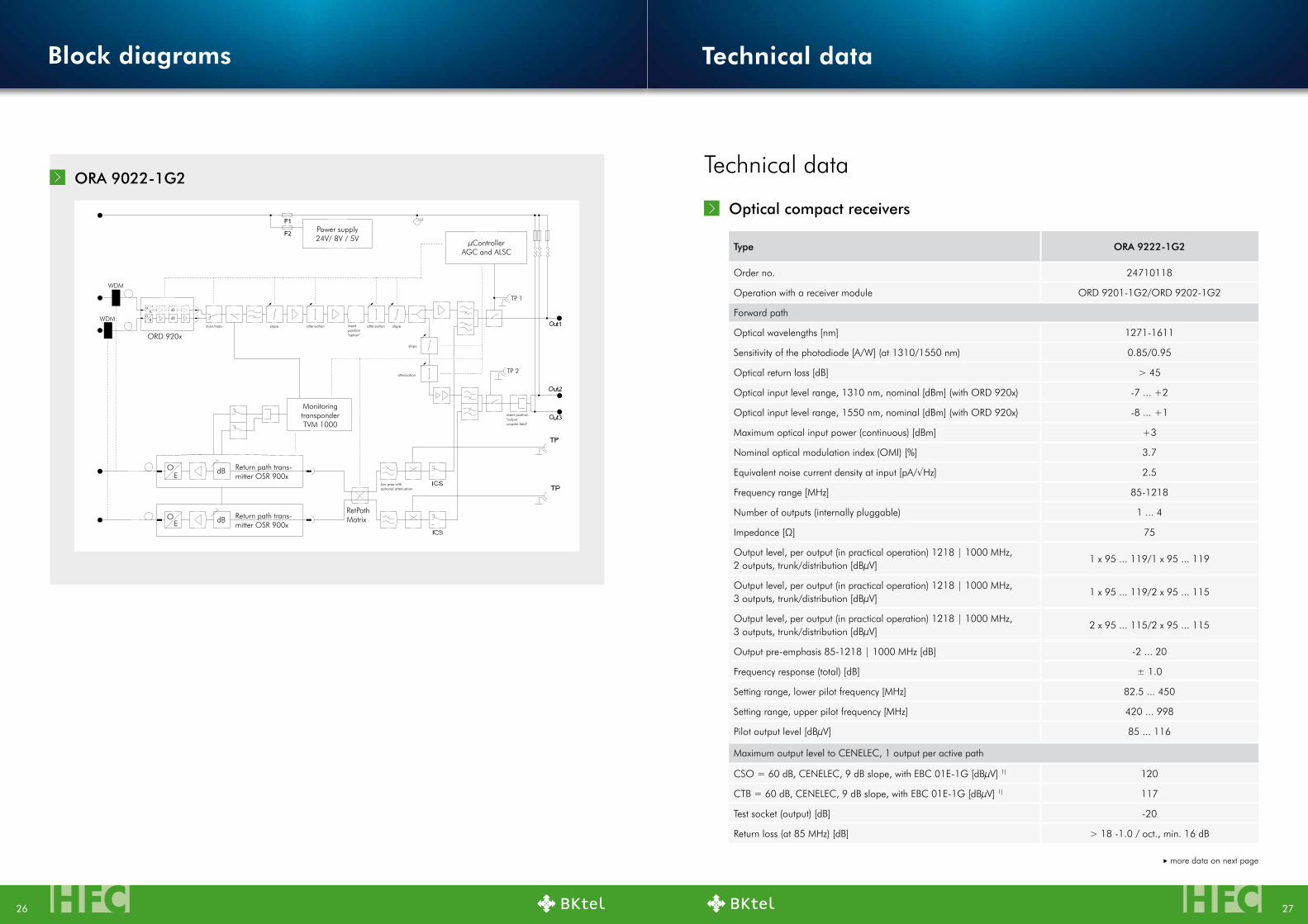
ORA 9222-1G2 with ORD 9201/9202-1G2
Block diagrams
Optical micro-nodes for RFoG Block diagramms
HFCHFC 2726
ORA 9022-1G2
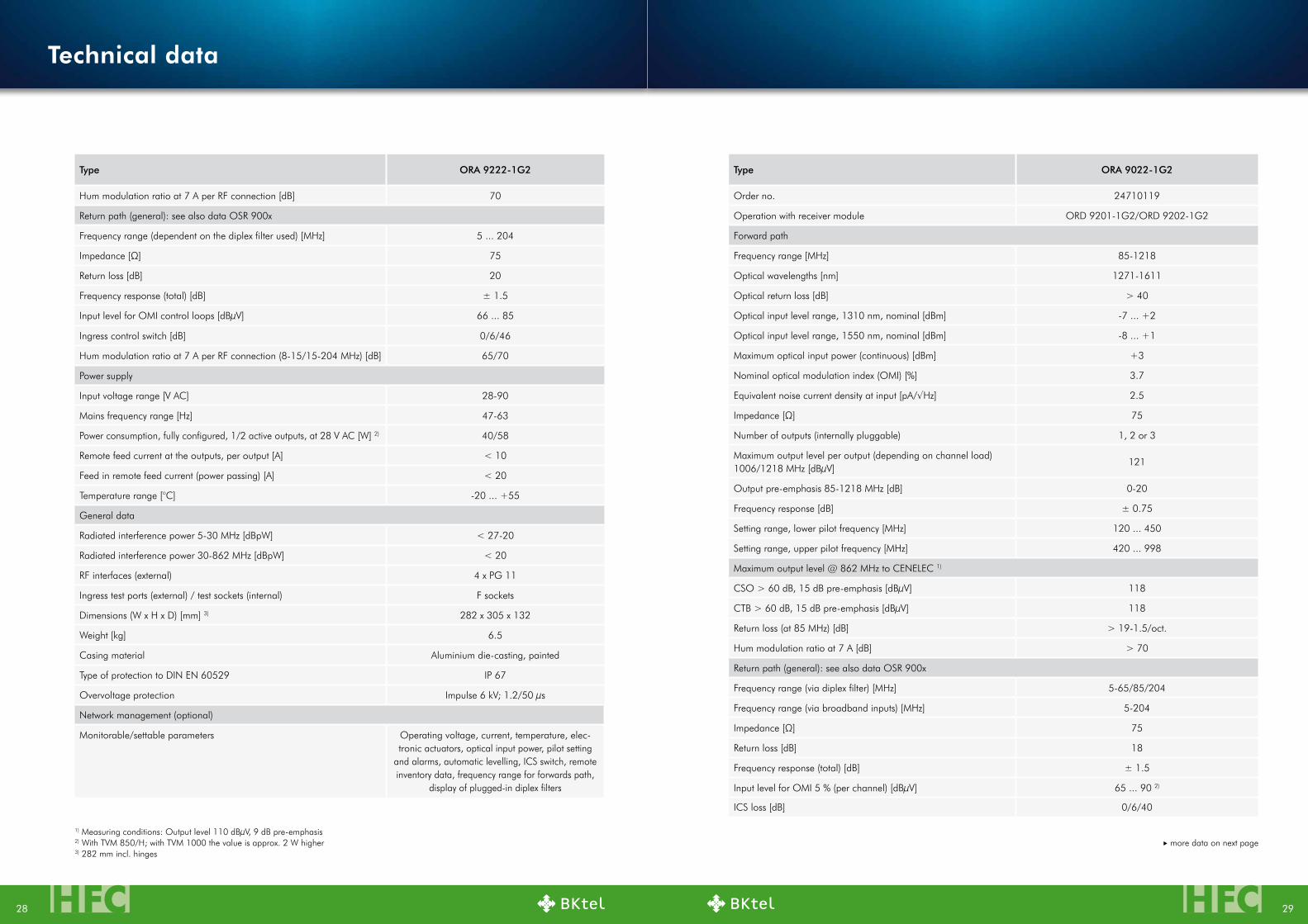
Optical compact receivers
Type ORA 9222-1G2
Order no. 24710118
Operation with a receiver module ORD 9201-1G2/ORD 9202-1G2
Forward path
Optical wavelengths [nm] 1271-1611
Sensitivity of the photodiode [A/W] (at 1310/1550 nm) 0.85/0.95
Optical return loss [dB] > 45
Optical input level range, 1310 nm, nominal [dBm] (with ORD 920x) -7 ... +2
Optical input level range, 1550 nm, nominal [dBm] (with ORD 920x) -8 ... +1
Maximum optical input power (continuous) [dBm] +3
Nominal optical modulation index (OMI) [%] 3.7
Equivalentnoisecurrentdensityatinput[pA/√Hz] 2.5
Frequency range [MHz] 85-1218
Number of outputs (internally pluggable) 1 ... 4
Impedance[Ω] 75
Output level, per output (in practical operation) 1218 | 1000 MHz, 2 outputs, trunk/distribution [dBµV]
1 x 95 ... 119/1 x 95 ... 119
Output level, per output (in practical operation) 1218 | 1000 MHz, 3 outputs, trunk/distribution [dBµV]
1 x 95 ... 119/2 x 95 ... 115
Output level, per output (in practical operation) 1218 | 1000 MHz, 3 outputs, trunk/distribution [dBµV]
2 x 95 ... 115/2 x 95 ... 115
Output pre-emphasis 85-1218 | 1000 MHz [dB] -2 ... 20
Frequency response (total) [dB] ± 1.0
Setting range, lower pilot frequency [MHz] 82.5 ... 450
Setting range, upper pilot frequency [MHz] 420 ... 998
Pilot output level [dBµV] 85 ... 116
Maximum output level to CENELEC, 1 output per active path
CSO = 60 dB, CENELEC, 9 dB slope, with EBC 01E-1G [dBµV] 1) 120
CTB = 60 dB, CENELEC, 9 dB slope, with EBC 01E-1G [dBµV] 1) 117
Test socket (output) [dB] -20
Return loss (at 85 MHz) [dB] > 18 -1.0 / oct., min. 16 dB
more data on next page
Technical data
Power supply24V/ 8V / 5V
Monitoring transponderTVM 1000
µControllerAGC and ALSC
RetPathMatrix
ORD 920x
WDM
TP 1
TP 2
WDM
dB
dB
dB
dB
OE
EO
Return path trans-mitter OSR 900x
Return path trans-mitter OSR 900x
main/redu slope attenuation attenuation
attenuation
low pass withoptional attenuation
slope
slope
insert position"outputcoupler field"
insert position"option"
Block diagrams Technical data
HFCHFC 2928
Type ORA 9222-1G2
Hum modulation ratio at 7 A per RF connection [dB] 70
Return path (general): see also data OSR 900x
Frequency range (dependent on the diplex filter used) [MHz] 5 ... 204
Impedance[Ω] 75
Return loss [dB] 20
Frequency response (total) [dB] ± 1.5
Input level for OMI control loops [dBµV] 66 ... 85
Ingress control switch [dB] 0/6/46
Hum modulation ratio at 7 A per RF connection (8-15/15-204 MHz) [dB] 65/70
Power supply
Input voltage range [V AC] 28-90
Mains frequency range [Hz] 47-63
Power consumption, fully configured, 1/2 active outputs, at 28 V AC [W] 2) 40/58
Remote feed current at the outputs, per output [A] < 10
Feed in remote feed current (power passing) [A] < 20
Temperaturerange[°C] -20 ... +55
General data
Radiated interference power 5-30 MHz [dBpW] < 27-20
Radiated interference power 30-862 MHz [dBpW] < 20
RF interfaces (external) 4 x PG 11
Ingress test ports (external) / test sockets (internal) F sockets
Dimensions (W x H x D) [mm] 3) 282 x 305 x 132
Weight [kg] 6.5
Casing material Aluminium die-casting, painted
Type of protection to DIN EN 60529 IP 67
Overvoltage protection Impulse 6 kV; 1.2/50 µs
Network management (optional)
Monitorable/settable parameters Operating voltage, current, temperature, elec-tronic actuators, optical input power, pilot setting
and alarms, automatic levelling, ICS switch, remote inventory data, frequency range for forwards path,
display of plugged-in diplex filters
1) Measuring conditions: Output level 110 dBµV, 9 dB pre-emphasis 2) With TVM 850/H; with TVM 1000 the value is approx. 2 W higher 3) 282 mm incl. hinges
Type ORA 9022-1G2
Order no. 24710119
Operation with receiver module ORD 9201-1G2/ORD 9202-1G2
Forward path
Frequency range [MHz] 85-1218
Optical wavelengths [nm] 1271-1611
Optical return loss [dB] > 40
Optical input level range, 1310 nm, nominal [dBm] -7 ... +2
Optical input level range, 1550 nm, nominal [dBm] -8 ... +1
Maximum optical input power (continuous) [dBm] +3
Nominal optical modulation index (OMI) [%] 3.7
Equivalentnoisecurrentdensityatinput[pA/√Hz] 2.5
Impedance[Ω] 75
Number of outputs (internally pluggable) 1, 2 or 3
Maximum output level per output (depending on channel load) 1006/1218 MHz [dBµV]
121
Output pre-emphasis 85-1218 MHz [dB] 0-20
Frequency response [dB] ± 0.75
Setting range, lower pilot frequency [MHz] 120 ... 450
Setting range, upper pilot frequency [MHz] 420 ... 998
Maximum output level @ 862 MHz to CENELEC 1)
CSO > 60 dB, 15 dB pre-emphasis [dBµV] 118
CTB > 60 dB, 15 dB pre-emphasis [dBµV] 118
Return loss (at 85 MHz) [dB] > 19-1.5/oct.
Hum modulation ratio at 7 A [dB] > 70
Return path (general): see also data OSR 900x
Frequency range (via diplex filter) [MHz] 5-65/85/204
Frequency range (via broadband inputs) [MHz] 5-204
Impedance[Ω] 75
Return loss [dB] 18
Frequency response (total) [dB] ± 1.5
Input level for OMI 5 % (per channel) [dBµV] 65 ... 90 2)
ICS loss [dB] 0/6/40
more data on next page
Technical data

HFCHFC 3130
Type ORA 9022-1G2
Power supply
Input voltage range [V AC] 30-90
Mains frequency range [Hz] 47-63
Power consumption incl. an ORD 9201, 1/2 active outputs [W] 26/37
Power consumption fully equipped, 1/2 active outputs [W] 4) 32/43
Remote feed current at the outputs [A] 12
Feed in remote feed current (power passing) [A] 20
General data
Radiated interference power 5-30 MHz [dBpW] < 27-20
Radiated interference power 30-862 MHz [dBpW] < 20
RF interfaces (external) PG 11
Ingress test sockets/broadband inputs (external) F sockets
Dimensions (W x H x D) [mm] 280 3) × 125 × 244
Weight [kg] 3.6
Casing material Aluminium die-casting, painted
Type of protection to DIN EN 60529 IP 54
Temperaturerange(inoperation)[°C] -20 ... +55
Network management (optional)
Monitorable/settable parameters
Operating voltage, current, temperature, electronic actuators, optical input power, pilot setting and alarms, automatic levelling, ICS switches, remote inventory data, frequency range for forward path, display of plugged-in
diplex filters
Components
Type WTe 10
Order no. 25010086
WiFi standard IEE 802.11 b/g/n
Frequency range [GHz] 2.4
Encryption WPA, WPA2 AES PSK
Maximum transmission power [dBm] +18
Ambienttemperaturerange[°C] -20 to +50
Housing protection class (to EN 60529) IP 54
1) Measuring conditions: Output level 110 dBµV, 15 dB pre-emphasis, 1 output 2) 3 dB less if return path segmentation is active 3) 307 mm incl hinges 4) With TVM 850/H; with TVM 1000 the value is approx. 2 W higher
Type eAC 90-1G2 eAC 93-1G2 eAC 94-1G2 eBC 90-1G2
Order no. 24510215 24510216 24510220 24510214
Frequency range [MHz] 5-1218
Through loss 5-15 MHz [dB] ¹) < 1.5 < 2.2 < 0.3 < 3.4
Through loss 15-65 MHz [dB] ¹) < 1.3 < 2.0 < 0.3 < 3.4
Through loss 65-862 MHz [dB] ¹) < 1.3 < 2.7 < 0.6 < 3.5
Through loss 862-1006 MHz [dB] ¹) < 1.5 < 3.1 < 0.7 < 3.7
Through loss 1006-1218 MHz [dB] ¹) < 1.6 < 3.1 < 0.9 < 3.9
Tap loss [dB] 10 6 20 As for through
loss
Decoupling/directional attenuation [dB] 28 26
Impedance[Ω] 75
¹) The through loss is the attenuation of the signal between the signal output of the device and output 1 if used in the output insert position or between the input and tap input if used in the input insert position (loop-through input splitter field)
Type TVM 1000 TVM 850/H TVM 500
Order no. 26210086 26210077 26210846
Input frequency range [MHz] 90-862 75-90.5 300-320; 425-450; 863-870; 902-928
Input level range [dBµV] 48-78 50-95 48-95
Output frequency range [MHz] 5-65 5-42 -
Max. output level [dBµV] 113-118 105 -
Power consumption [W] 3.5 1 0,4
Transmission protocol DOCSIS/EuroDOCSIS 2.0 HMS 2 FSK
For device types VGO 939-1G, VGF 939-1G, VOS 952-1G, VOS 953-1G, ORA 9222-1G2/-1G, ORA 9022-1G2/-1G, ORA 920/921,
VGP 9033-1G, VGP 9041 from version A02 (Nov. 2008), VGF 9030/9040, VGP 9236-1G, VGP 9240,
VGP 9x43 D-1G2
ORA 9222-1G/1G2; ORA 9022-1G/1G2;
VGP 9x43D-1G2; VGF 939D-1G
Type eBC 01e-1G2 eBC 00-1G2
Order no. 24510230 24510217
Frequency range [MHz] 5-1218 5-1218
Through loss [dB] < 0.5
Technical data

HFCHFC 3332
Type BMWR 1310/1550 BMWR 1310
Order no. 24810098 24810197
Wavelength of the "pass channel" [nm] 1310 ± 40 1310 ± 6.5
Wavelength of the "reflect channel" [nm] 1550 ± 50 C05 ... C18
Through loss of the "pass channel" [dB] ¹) 0.7 -
Through loss of the "common pass channel" [dB] ¹) - 0.6
Through loss of the "pass channel common" [dB] ¹) - 0.6
Through loss of the "common reflect channel" [dB] ¹) - 0.6
Selection (adjacent channel) [dB] - ≥ 30
Selection (non-adjacent channel) [dB] - ≥ 40
Type OFC 90/sC OFC 90/sC-e
Order no. 24810101 24810102
Length [cm] 90
Diameter of the patch cord [mm] 0.9
Attenuation of the optical plug connectors [dB] 0.3
Type OsR 9003 OsR 9003 P65-Cxx
Order no. 24610201 24610xxx
Optical wavelength(s) [nm] 1310 1471/1491/1511/1531/1551/1571/
1591/1611
Optical output power [dBm] +3 (+6) ¹)
Frequency range [MHz] 5-204
Relative intensity noise (RIN) [dB/Hz] -155
Impedance[Ω] 75
Return loss (5 MHz) [dB] > 18
Second pilot tone [MHz] - 65
OMI second pilot tone [%] - 2 ± 0.5
Network management (optional)
Monitorable/settable parametersOptical output power; modulation index; laser current; pilot tone setting;
line coding; various configuration settings
¹) Switchable when used in the ORA 9022-1G or ORA 9222-1G2/-1G
more data on next page
¹) Without plug connector
Type BMWR 1310/1550 BMWR 1310
PDL [dB] - ≤0.15
Through loss of the "reflect channel" [dB] ¹) 0.45 -
Directional attenuation of the "pass/reflect channel" (forward/return path) [dB]
50 55
Optical return loss [dB] 45 50
Max. optical power [mW] 500
Dimensions (length x diameter) [mm] 39 x 5.5 34 x 5.5
Operatingtemperature[°C] - 0 ... +70
Fibre SMF, 0.9 mm loose tube, l = 1 m
Optical plug connectors SC/APC
more data on next page
Optical micro-nodes for RFoG
Type ORA 110D-RFoG ORA 118D-RFoG ORA 119D-RFoG
Order no. 24710071 24710072 24710073
Forward path
Optical data
Frequency range [MHz] 85-1006
Optical wavelengths (reception) [nm] 1550 ... 1560 1250 ... 1360
Sensitivity of the photodiode at 1550 nm [A/W]
0.9
Optical return loss [dB] > 45
Equivalent noise current density at input [pA/√Hz]
5
Optical input level range [dBm] -6 ... +0
Nominal optical modulation index (OMI) [%] 4.4
Optical interface 1 x SC/APC
RF data
Impedance[Ω] 75
Number of outputs 1
Output level (1 GHz at 4.4 % OMI), switchable [dBµV]
83/99 ± 1.5
Frequency response [dB] ± 1.0
Technical data
HFCHFC 3534
Type ORA 110D-RFoG ORA 118D-RFoG ORA 119D-RFoG
Additional frequency response (over the optical input power range and temperature range) [dB]
± 1.0
Pre-emphasis 85 ... 1006 MHz (output: 88 dBµV or 99 dBµV) [dB]
3 ... 5
Output level for CSO 60 dB to CENELEC 41 (pin = 0 dBm) for 83/99 dBµV setting [dBµV]
84/100
Output level for CTB 60 dB to CENELEC 41 (pin = 0 dBm) for 83/99 dBµV setting [dBµV]
84/99
Return loss (85 MHz) [dB] 18 -1.5/oct.
Test socket attenuation [dB] 20 ± 1
Return path (general)
RF data
Frequency range (via diplex filter/via broadband input) [MHz]
5-65
Impedance[Ω] 75
Return loss (5-65 MHz) [dB] 20
Frequency response [dB] ± 1
Test socket attenuation (upstream in/out) [dB] 20 ± 1
Input level for OMI 12 % (jumpers 0 dB, 10 dB, 20 dB) [dBµV]
80/90/100
Input level range [dBµV] 75 ... 105
Return path laser Fabry-Perot laser diode DFB laser diode
Return path laser diode wavelength [nm] 1310 ± 20 1610 ± 3
Optical output power [dBm] +3
Laser on/off time [µs] 0.95
Power supply
Input voltage [V AC] 230
Power consumption [W] 5
General data
Casing material Zinc die-casting
RF output F socket
Dimensions (W x L x H) [mm] 105 x 155 x 54
Weight [kg] 0.8
Temperaturerange(inoperation)[°C] -5 ... +45
Type Order no.
B
BWMR 1310 24810197
BWMR 1310/1550 24810098
E
EAC 90-1G2 24510215
EAC 93-1G2 24510216
EAC 94-1G2 24510220
EBC 00-1G2 24510217
EBC 01E-1G2 24510230
EBC 90-1G2 24510214
EMU 29 273243
EMP 53 25010011
EMP 34 275289
EMP 35 275300
ERR 9065 24510156
ERR 9085 24510158
ERR 9204 24510211
ERS 9085-1G2 24510219
ERS 9105-1G2 24510223
ERS 9258-1G2 24510210
O
OFC 90/SC 24810101
OFC 90/SC-E 24810102
OKU 01/SC 24810031
OKU 01/SC-E 24810099
OKU 01/E 24810100
ORA 110D-RFoG 24710071
ORA 118D-RFoG 24710072
ORA 119D-RFoG 24710073
ORA 9022-1G2 24710119
ORA 9222-1G2 24710118
Type Order no.
ORD 9201-1G2 24810347
ORD 9202-1G2 24810348
OSR 9003 24610201
OSR 9003 P65-Cxx 24610xxx
T
TVM 1000 26210086
TVM 850/H 26210077
W
WFS 906-1G2 24510218
WFS 908-1G2 24510222
WFS 920-1G2 24510209
WTE 10 25010086
Z
ZOH 04 24810159
ZGF 02 25510002
ZGF 03 25510003
Order number overview
Technical data

HFC36
05/2
017
Opt
ical
Com
pact
Rec
eive
r
BKtel communications GmbH
Benzstrasse 4 41836 Hueckelhoven-Baal Germany Phone: +49 (0) 24 33 / 91 22-0 Fax: +49 (0) 24 33 / 91 22-99
Office Kornwestheim: Bahnhofstrasse 82 70806 Kornwestheim Germany Phone: +49 (0) 71 54 / 1 59 90-0 Fax: +49 (0) 71 54 / 1 59 90-77
BKtel networks GmbH
Mangfallstrasse 3783026 Rosenheim Germany Phone: +49 (0) 80 31 / 7 96 75-0
Phone: +49 (0) 80 31 / 7 96 75-99
Internet: www.bktel.com Email: [email protected]
Representations:
BKtel Pacific Rim (Japan) Inc. Katsukou Building 5F 1-2-8, Hourai-cho, Naka-ku, Yokohama, Kanagawa 231-0048, Japan Phone: +81 45 350 5447 Fax: +81 45 350 5460 BKtel LatamOficina de RepresentaciónPedro Torres n.º 231, planta 302Municipalidad de ÑuñoaSantiago, ChilePhone: +56 220 468 46Email: [email protected]
BKtel local representatives:
France: André Balva [email protected]
South East Asia: Roland Wuerth [email protected]