![[5]Optical system design and engineering considerations,](https://static.fdocuments.net/doc/165x107/577cd9b91a28ab9e78a40605/5optical-system-design-and-engineering-considerations.jpg)
Optical and Manufacturing Processes and Considerations ... · PDF...
9
Optical and Manufacturing Processes and Considerations when Designing with Glass Molded Optics Written by Amber Luttmann December 2, 2013 1. Introduction In modern optical design and manufacturing, the tried and true method for creating optical lenses and surfaces is through grinding and polishing. With modern technology, very large numbers of spherical and flat parts can be made with very high optical precision very quickly, and at low cost. This is the standard method of fabrication. However, once aspheric surfaces are needed, these methods become much more involved. When grinding a polishing aspheric surfaces, normally numerous different grinding and milling techniques are needed, with frequent monitoring of the surface needed to create the proper shape. This dramatically increases production time and cost. This is where precision glass molding (PGM) can be used. This allow for rapid, repeatable, and cheap production of aspheric surfaces. This paper will discuss the process of manufacturing PGM optics, as well as outline some basic considerations and guidelines for their manufacturing, as well as designing optical systems that utilize them. While PGM optics have many advantages, these should be weighed against the costs before deciding to use them in an optical system. 2. Moldable Glass The first step in discussing using moldable glass optics in a design is discussing what moldable glass is. How is it different from typical optical glasses used in traditional optical design? The main characteristic that defines a glass as moldable is its glass transition temperature, or Tg. In moldable glasses, the glass transition temperature is much lower than in standard optical glass, with Tg < 600 C. As glass is heated it expands, but past a certain temperature, it begins to expand much more rapidly. The intersection between the two expansion rates is considered the Tg (see figure below).
Transcript of Optical and Manufacturing Processes and Considerations ... · PDF...
Optical and Manufacturing Processes and Considerations when Designing with Glass Molded Optics
Written by Amber Luttmann December 2, 2013
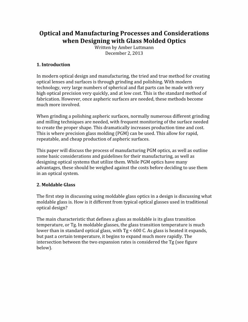
1. Introduction In modern optical design and manufacturing, the tried and true method for creating optical lenses and surfaces is through grinding and polishing. With modern technology, very large numbers of spherical and flat parts can be made with very high optical precision very quickly, and at low cost. This is the standard method of fabrication. However, once aspheric surfaces are needed, these methods become much more involved. When grinding a polishing aspheric surfaces, normally numerous different grinding and milling techniques are needed, with frequent monitoring of the surface needed to create the proper shape. This dramatically increases production time and cost. This is where precision glass molding (PGM) can be used. This allow for rapid, repeatable, and cheap production of aspheric surfaces. This paper will discuss the process of manufacturing PGM optics, as well as outline some basic considerations and guidelines for their manufacturing, as well as designing optical systems that utilize them. While PGM optics have many advantages, these should be weighed against the costs before deciding to use them in an optical system. 2. Moldable Glass The first step in discussing using moldable glass optics in a design is discussing what moldable glass is. How is it different from typical optical glasses used in traditional optical design? The main characteristic that defines a glass as moldable is its glass transition temperature, or Tg. In moldable glasses, the glass transition temperature is much lower than in standard optical glass, with Tg < 600 C. As glass is heated it expands, but past a certain temperature, it begins to expand much more rapidly. The intersection between the two expansion rates is considered the Tg (see figure below).
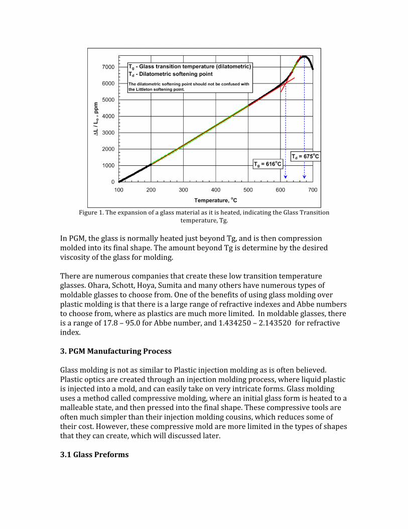
Figure 1. The expansion of a glass material as it is heated, indicating the Glass Transition
temperature, Tg. In PGM, the glass is normally heated just beyond Tg, and is then compression molded into its final shape. The amount beyond Tg is determine by the desired viscosity of the glass for molding. There are numerous companies that create these low transition temperature glasses. Ohara, Schott, Hoya, Sumita and many others have numerous types of moldable glasses to choose from. One of the benefits of using glass molding over plastic molding is that there is a large range of refractive indexes and Abbe numbers to choose from, where as plastics are much more limited. In moldable glasses, there is a range of 17.8 – 95.0 for Abbe number, and 1.434250 – 2.143520 for refractive index. 3. PGM Manufacturing Process Glass molding is not as similar to Plastic injection molding as is often believed. Plastic optics are created through an injection molding process, where liquid plastic is injected into a mold, and can easily take on very intricate forms. Glass molding uses a method called compressive molding, where an initial glass form is heated to a malleable state, and then pressed into the final shape. These compressive tools are often much simpler than their injection molding cousins, which reduces some of their cost. However, these compressive mold are more limited in the types of shapes that they can create, which will discussed later. 3.1 Glass Preforms
Glass molded optics are created by compression molding. This means that there must be some initial glass form placed within the mold. There are several different options to choose from, and they each have their own benefits and costs. 3.1.1 Spherical or Ball Preforms
Figure 2. Spherical Glass Preforms
These preforms are essentially ball lenses. These are created in large quantities by grinding large batches of glass pieces already near the appropriate volume, removing the sharp edges. They are then fine polished, and can achieve a very high quality surface finish. This can be very important, as molded glass optics retain all the properties of the preform. If there are any scratches, blemishes, or cracks, these will be transferred to the final lens. Ball preforms are chosen based on the final desired volume of the lens, and then matched with the volume of the ball preform. Most manufactures create ball lenses with diameters in the range of 1-‐8 mm. Anything else would need to be custom made, driving up the price. These can be made in large quantities for a fairly low cost, but small volumes will drive up the price significantly. 3.1.2 Gob Preforms
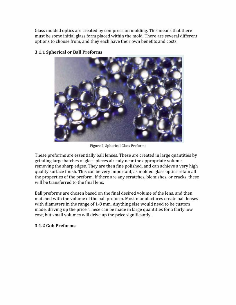
Figure 3. Gob Glass Preforms
Gob preforms are simply a set volume of glass used for molding. They can vary is shape, but the most common shape is a double convex oval, are a plano-‐convex oval, but convex shapes can be made as well. These are created by glass manufactures by pressing molten glass though a nozzle at a highly controlled pressure to create drops with very specific volumes. These preforms are the cheapest option, but do not offer the surface precision of ball preforms as there is no polishing step. 3.1.3 Disc Preforms Disc preforms are disc of glass that can can be polished to have very high surface precision. These are the recommended preform when creating concave lenses. These preforms also lead to the least amount of wasted material. While not as cheap as the previous options, these can still be an economical choice, while providing high quality surfaces. 3.1.4 Near Net Preforms These preforms have been pre-‐shaped to be close to the final lens shape desired after molding. As they require a large amount of pre-‐processing, they are the most expensive preform, and are normally only used in parts with complex shapes, and very large parts. 3.2 PGM Process The PGM process consists of 6 basic steps, along with the creation of tooling which are outlines below: 3.2.1 Tooling
Tooling is the first important and critical step in this process. Creating a high precision and robust tool will save you money per part and create high quality lenses. A lens produced in molding can never be better than the tool it was created on, which is why a high quality tool is of utmost importance. PGM tools consist normally of 2 parts. These 2 parts are the halves of the mold, which are held by the compression molding tool, and are brought together to compress the glass preform and create the lens. These mold are typically created out of Silicon Carbide or Tungsten Carbide, but other similar materials can be used. These are used to withstand the high heat of the molding process. These molds are created by first rough grinding the basic desired shape out of the carbide material. Then, the final polished is performed on a high precision Diamond turning machine, often specially configured for grinding carbides. After this, some post polishing may occur to remove the machining marks, but this can come at the cost of form error, so should be weighed against the specifications of the project. These molds are then often coated with a single or multi layer carbide or nitride in order to increase the longevity of the tool. This will be discussed later. 3.2.2 Manufacturing Process
1) Tooling After creation and qualification, the molds outlined above are placed in the compression molding tool, and used throughout the manufacturing process. 2) Insert Glass Preform A glass preform is introduced to the molding machine. 3) Evacuate The system is purged of oxygen, or sometimes even placed into vaccum, to prevent oxidization and prevent air from being trapped in the mold. 4) Heat Heat is applied, normally in the form of IR irradiation, to the glass and the tool, heating both up to the Tg of the glass. 5) Load Once Tg is reach, the tool is moved to apply a compressive force on the glass, reshaping it into its final form. 6) Cool The tooling and the glass are quickly cooled and annealed, normally by the introduction of nitrogen gas. 7) Remove
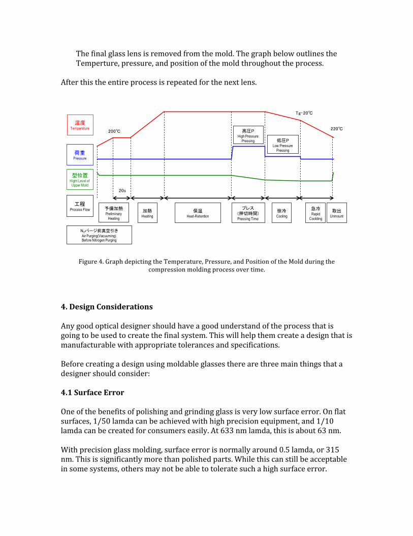
The final glass lens is removed from the mold. The graph below outlines the Temperture, pressure, and position of the mold throughout the process.
After this the entire process is repeated for the next lens.
Figure 4. Graph depicting the Temperature, Pressure, and Position of the Mold during the
compression molding process over time. 4. Design Considerations Any good optical designer should have a good understand of the process that is going to be used to create the final system. This will help them create a design that is manufacturable with appropriate tolerances and specifications. Before creating a design using moldable glasses there are three main things that a designer should consider: 4.1 Surface Error One of the benefits of polishing and grinding glass is very low surface error. On flat surfaces, 1/50 lamda can be achieved with high precision equipment, and 1/10 lamda can be created for consumers easily. At 633 nm lamda, this is about 63 nm. With precision glass molding, surface error is normally around 0.5 lamda, or 315 nm. This is significantly more than polished parts. While this can still be acceptable in some systems, others may not be able to tolerate such a high surface error.
1.2 弊社評価試験におけるプレス成形の基本成形パターン
Evaluation tests: basic molding pattern of press molding at OHARA
本資料に記載のデータは、下図に示す成形パターンを基本とした成形条件にて行ったものです。
The data in this brochure was obtained utilizing the molding conditions shown in the following graph.ただし、弊社における試験条件であって、モールドプレス成形の推奨条件ではありません。
The information shown illustrates OHARA’s test forming and molding conditions.Please use this data for reference purposes only.This is not the conditions of forming and molding OHARA recommends.
200℃
Tg-20℃
加熱Heating
保温Heat-Retention
高圧PHigh Pressure
Pressing
プレス(押切時間)Pressing Time
低圧PLow Pressure
Pressing
徐冷Cooling
予備加熱Preliminary
Heating
温度Temperature
工程Process Flow
荷重Pressure
型位置Hight Level of Upper Mold
20s
急冷Rapid
Coolding
取出Unmount
220℃
N2パージ前真空引きAir Purging(Vacuuming) Before Nitrogen Purging
6 Technical Data ~Pressing & Forming for Low Tg Optical Glasses~ Ver.4.2
4.2 Size The smallest size lens that is traditionally made with molding optics is about 1 mm in diameter and 2 mm center thickness. Anything smaller than this and specialized preforms will have to be made, and well as specialized machinery to control the pressure. This can be achieved, but will drive up price. If small optics are needed, normally several small lenses are created together, and then cut apart in post-‐processing. The largest lens normally made by molding is 8 mm in diameter at about 5 mm center thickness. Anything larger than this and the glass with not cool evenly, which can lead to deformation and even cracking. For very large lenses, other methods should be considered. Besides these two factors, the final volume of the lens must be considered. Glass manufactures tend to make a discrete number of preforms, of specific volumes. If your lenses to not work for these volumes, they will need to create custom preforms, which will drive up the cost of your final design. 4.3 Complexity Because molded glass is created in compression molding, complex shapes often cannot be made. The standard minimum radius on any edge is 0.3 mm, which will limit the size of small features. In may also limit the amount of mounting features that can be directly molded into the glass, which is one of the benefits of plastic injection molded parts. 4.4 Refractive Index Error As stated before, the cooling period of these parts is very rapid. Normally a molder will cool the parts are rapidly as possible to reduce cycle time on the tool, and increase productivity. This often leads to residual stress in the parts, which can lead to a refractive index error as large as 0.005. This needs to be considered when tolerancing the optical system. This residual stress can also lead to birefringence in the part. This is not something normally considered when using glass parts. If polarization is a crucial element of the optical system, molded optics may not be able to be used. 4.5 Benefits Of course, PGM comes with many benefits. The first of which was mentioned before, which is that aspheric surfaces can be created rapidly and precisely. Another is that because these are glass parts, they will have a much lower CTE value than there plastic counter parts, so they will be more robust over a wider thermal range.
A very large benefit of PGM is that insert molding can be used. Insert molding is a technique where metal parts are introduce to the mold, and the glass is molded into them, and they become a part of the final lens. This has numerous possibilities. Since PGM parts are often limited in their mounting features, the parts can be molded directly into housings with very small tolerances. This gives the designer a great deal of flexibility. 5. Manufacturing Considerations Much of the manufacturing considerations for PGM come into play with the mold and tooling. The tooling is the bulk of the cost in your processing. Where as in traditional optics manufacturing each part may have a higher individual cost, in PGM, each part has a very low cost, but the tool itself has a very high initial cost. The longer you can make your tool last, the lower cost per piece you will have. 5.1 Mold Design The more simplistic the mold design, the cheaper the tools, as well as decreased likelihood of damage during processing. If additional faces or interfaces are needed, make sure that they do not create excessively sharp corners, which can be damaged during molding. The mold will expand during heating, just like the glass. It is important to model the behavior to the mold as it is heated. This will prevent and damage from occurring because of interaction between the molded parts during heating. It will also allow the mold designer to create a shape the properly adjusts for heating, and creates the correct surface profile at the highest heating temperature needed. 5.2 Mold Coating As mentioned before, there are numerous coatings that can be added to the carbide mold. These need to be chosen based on many factor. Their main purpose is to prevent oxidation of the mold, but they also must protect the mold from scratches or blemishes, which will be transferred to the molded parts. The coating must also be chosen to be inert with relation to the glass material being molded. Any reaction could cause unfixable damage to the mold. These coatings should also allow easy release from the mold, so that the parts and mold are not damaged during removal. 6. Conclusion While molded glass optics have many advantages, it is important to not treat them as ground and polished glass optics during the design process. They have different
limitations than traditional glass optics, as well as plastic optics. They are extremely useful in the mass production of aspheres, for speed and cost. If all of the design and manufacturing considerations presented above are considered during system design, then a very high quality optical system can be created quickly and at low cost. 7. References Symmons, A. (2011). Glass Molded Optics. In Molded Optics: Design and Manufacture (pp. 165-‐207). Boca Raton, LA. CRC Press. Deegan, John. “Precision Glass Molding Technical Brief.” RP Optics. (2007). Symmons, Alan. Auz, Bryan. “Design Considerations and Manufacturing Limitations of Insert Precision Glass Molding.” Procd. Of SPIE Vol. 8489. Image taken from Wikipedia and Ohara Glass Catalog.