OPTI torque - krechina.com Clutches/OPTI torque/K... · Compared to an overcurrent relay, or other...
12
K.460.V06.GB OPTI torque www.mayr.de power transmission Cost ef fective overload pr otection Cost ef fective overload pr otection Ball/detent torque limiter ● Accurate, reliable torque control ● Wide torque range ● Unique system for setting torque
Transcript of OPTI torque - krechina.com Clutches/OPTI torque/K... · Compared to an overcurrent relay, or other...

K.460.V06.GB
OPTI torque
ww
w.m
ayr.d
e
powertransmission
Cost effectiveoverload protectionCost effectiveoverload protection
Ball/detent torque limiter
● Accurate, reliable torque control● Wide torque range● Unique system for setting torque

2
®
powertransmission
Why use a torque limiter ?
Why use OPTI torque ?
The concept:
A torque limiter is a mechanical device that disengages when thetransmitted torque exceeds a pre-set value, i.e. when an overloadoccurs.
People, products, drives, equipment and machines can be protectedagainst the damage caused by overloads, and the costly repairs andunnecessary downtime which can result.
Compared to an overcurrent relay, or other electrical overloaddevices a torque limiter not only provides a signal in the event of anoverload, but instantaneously disengages, isolating the inertia energyof the drive system.
OPTI torque increases productivity byeliminating expensive machine downtime.
Only OPTI torque offers all the following advantages
* OPTI torque assures precise torque contol. Even in extreme conditions, repetitive accuracies of +/-5% are achieved.
* The OPTI torque system of differing spring weights and configurations results in wide torque ranges for all size units. Low torque applications with large shaft diameters are possible.
* OPTI torque’s small size yields low mass moments of inertia.
* OPTI torque offers a unique system for setting the overload torque,making adjustment both easy and accurate.
* OPTI torque features a positive locking arrangement, preventingtorque setting changes during operation.
* OPTI torque’s large diameter limit switch plate allows the use ofcommercially available, inexpensive limit switch (see page 11).Promixity sensors can be used without limit switch plate installed.
Engineering Assistance
Please let us know what your specific requirements are und we will behappy to work out, without any obligation, a detailed recommendation. Since our engineers cannot be aware of all applications and control allfactors that may affect the function of our products, our warranty applies only to products manufactured by Mayr.
In accordance with our established policy to constantly improve ourproducts, the specifiations contained herein are subject to changewithout notice.
The practical solution:
Many years of experience developing, improving and manufacturingtorque limiting clutches enable us to now offer the ideal mechanicaltorque limiter for virtually every application. The latest productiontechniques and quality control systems guarantee consistently highquality products that are economically priced.
Basic function of OPTI torque:
OPTI torque is a ”ball/roller detent torque limiting clutch“, transmittingtorque via balls and detents (multiple position reset) or rollers areheld in their respective detents through the pressure generated bydisc springs. When an overload occurs, exceeding the pre-settorque, the balls or rollers ride out of their detents, disengaging theclutch.The balls or rollers riding out of their detents produce the axial strokeof the limit switch plate, which is used to actuate a mechanical limitswitch to shut down the drive. Alternatively, the OPTI torque can beused without a limit switch plate and a proximity switch sensing theaxial movement of the control element.The limiting torque for an overload is set by adjusting the springpressure on the balls or rollers. This is done by means of an adjustingnut, which is positively locked once the torque has been set.As OPTI torque utilizes rolling disengagement, torque changes dueto frictional wear, as in friction type torque limiters, are eliminated.Consistent and repeatable torque settings, unaffected by outsideinfluences such as temperature, humidity or lubrication are theresult.
Options and special designs:
Double “C” face or IEC-flange torque limiter.For installation between motor and gear box.
Design for small drive elements.
Covered and sealed units for dusty environmentsor severe conditions, such as high pressure wash down.
Optional finishesOPTI torque standard finish is zinc phosphating.Alternative finishes, such as nickel plating, etc., are available uponrequest.

3
®
powertransmissionOPTI torque
OPTI torque multiple position clutch- for immediate re-engagement
The 24 balls in the OPTI torque multiple position clutch ratchet fromone set of detents to the next during an overload. The multiple positionOPTI torque therefore immediately and automatically re-engages, as soon as the overload has been cleared. Residual torque transmittedduring an overload is substantially lower than the pre-set torque.
OPTI torque single position clutch- for timing and sequencing
By utilizing 6 unequally spaced rollers, the OPTI torque single positionclutch automatically re-engages after one full revolution, once theoverload has been cleared. As re-engagement is at the exact positionof disengagement, timing and/or sequencing within the machine ismaintained. Residual torque transmitted in disengaged position issubstantially lower than the pre-set torque.
OPTI torque are available in two basic types:
Components:
1 standard hub2 extended hub3 output flange multiple position4 output flange single position5 control element multiple position6 control element single position7a ball cage7b roller8 axial bearing9 spring
10 adjusting nut11 lock washer12 locking screw13 limit switch plate

4
®
powertransmission OPTI torque
* Torque: It is essential to determine the torque at the point whereOPTI torque will be mounted.The torque should be based on allowable torque for the drive components. Alternatively torque can be calculated from the motorhorsepower and operating speed.Remember to consider peak torques due to start-up or otheroperating conditions that should not lead to disengagement ofclutch.
* Shaft diameter: The overlaps in torque ranges from one size OPTItorque to the next allow different size units to be utilized for thesame torque requirement. The determining factor then becomesshaft diameter.
OPTI torque’s adaptability makes selection easy.
Two basic parameters to be considered:
Selection Procedure:
The most effective location for OPTI torque is as close as possible tothe potential trouble spot or the drive component which must be protected. Keep in mind the more inertia that is disengaged, results inless engery that can cause damage.
The figures below show the recommended locations for OPTI torquein two typical drive arrangements. Alternate locations A, B and Cprovide less effective protection, especially when large speedreductions occur beyond the OPTI torque.
Location of OPTI torque:
5
®
powertransmissionOPTI torque
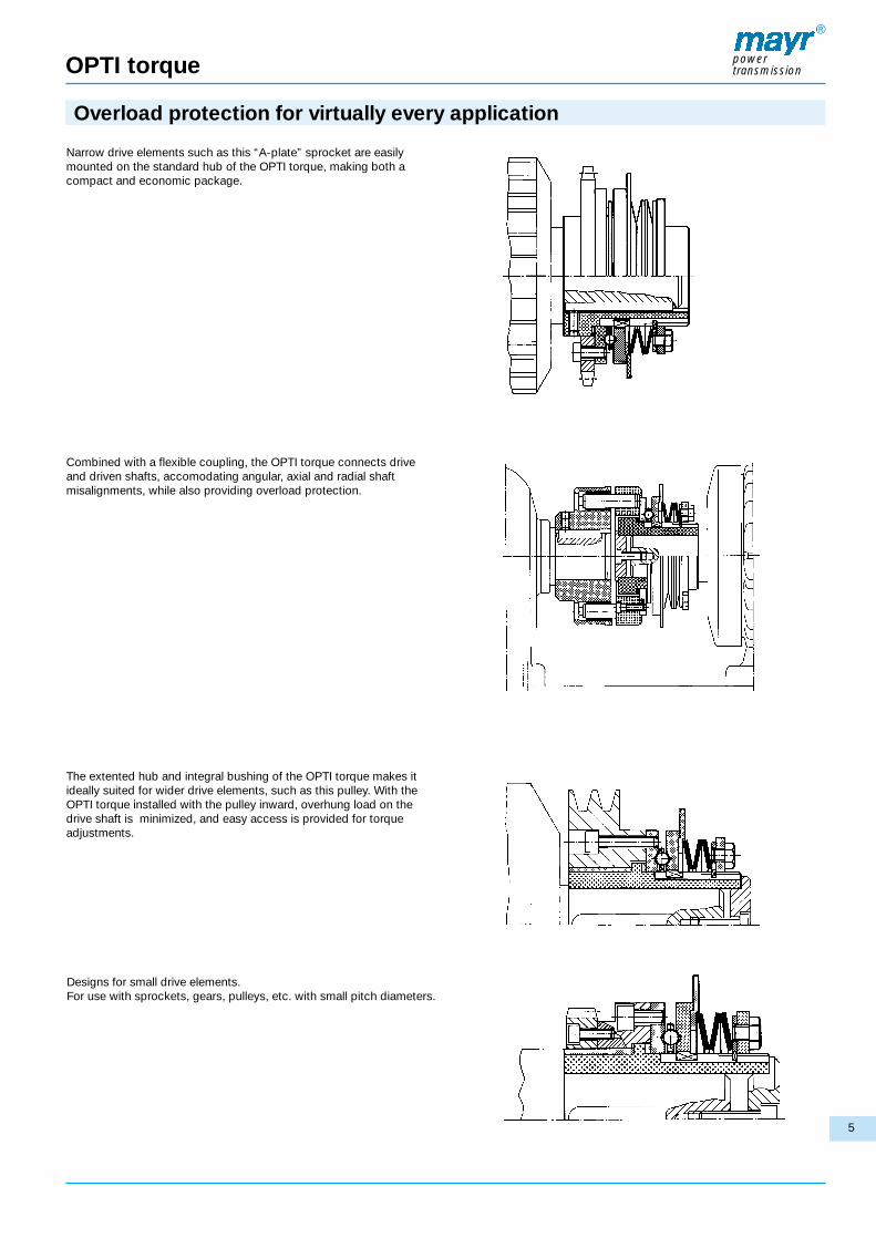
The extented hub and integral bushing of the OPTI torque makes itideally suited for wider drive elements, such as this pulley. With theOPTI torque installed with the pulley inward, overhung load on thedrive shaft is minimized, and easy access is provided for torqueadjustments.
Combined with a flexible coupling, the OPTI torque connects driveand driven shafts, accomodating angular, axial and radial shaftmisalignments, while also providing overload protection.
Narrow drive elements such as this “A-plate” sprocket are easilymounted on the standard hub of the OPTI torque, making both acompact and economic package.
Designs for small drive elements.For use with sprockets, gears, pulleys, etc. with small pitch diameters.
Overload protection for virtually every application

6
OPTI torque multiple /single position clutch
®
powertransmission
Technical data and Dimensions
Type 460._1_.0
OPTI torque with standard hub
Type 460._1_.1
OPTI torque with extended hub
All other dimensions same as type 460._ _ _ .0.
Please notice that all threads for set screws asshown above are provided only when orderedfinish bored.
size dim.type
46_.410._
26 – 533 – 6
53 – 1066 – 12
142 – 26516 – 30
265 – 53130 – 60
354 – 79640 – 90
53 – 1066 – 12
106 – 22112 – 25
265 – 53130 – 60
531 – 106260 – 120
796 – 177090 – 200
0
1
2
3
4
lbf x inNm
lbf x inNm
lbf x inNm
lbf x inNm
lbf x inNm
106 – 22112 – 25
221 – 44225 – 50
531 – 106260 – 120
1062 – 1770120 – 200
1770 – 3363200 – 380
221 – 35425 – 40
442 – 70850 – 80
1062 – 1770120 – 200
1770 – 2655200 – 300
3363 – 5753380 – 650
53 – 1066 – 12
106 – 22112 – 25
265 – 53130 – 60
531 – 106260 – 120
442 – 132850 – 150
106 – 22112 – 25
221 – 44225 – 50
531 – 106260 – 120
1062 – 1770120 – 200
1328 – 3098150 – 350
221 – 35425 – 40
442 – 70850 – 80
1062 – 1770120 – 200
1770 – 2655200 – 300
3098 – 5753380 – 650
500
500
500
500
500
type46_.510._
type46_.610._
type46_.710._
type46_.415._
type46_.515._
type46_.615._
max.speedrpm
torque rangesmultiple position clutch single position clutch
size dim. multiplepositionclutch
singlepositionclutch
0.0471,2
0.0792,0
0.0902,3
0.1022,6
0.1022,6
0.0471,2
0.0591,5
0.0751,9
0.0872,2
0.0872,2
0.45211,5
0.64916,5
0.64916,5
0.86622
0.86622
0.1574
0.1774.5
0.2165.5
0.2757
0.55114
0.1975
0.2366
0.2366
0.2757
0.3148
0.85421,7
0.84621,5
1.07527,3
1.33033,8
1.57540
0.83421,2
0.83821,3
1.08327,5
1.32733,7
1.65041,9
0.3759
0.437512
0.562515
0.7520
125
0.812520
125
1.37535
1.7545
2.16555
0.43711
0.512
0.62515
0.7520
125
1.18730
1.62542
1.62542
2.31260
2.31260
0
1
2
3
4
in mmin
mmin
mmin
mmin
mm
a a1 b
__
__
__
__
2.20456
d2
__
__
__
__
2.36260
a2type 46_._10._
ctype 46_._15._
cdmin dmax d1 min d1 max
stroke of outputflange and limitswitch plate t
*Counterbore a2/Ød2 only with size 4

* See technical data, torque ranges
1) please see page 8 for machining of drive elements2) hexagon socket bolt DIN 79913) not with single position clutch
In accordance with our established policy to constantly improve our products,the specifications contained herein are subject to change without notice.
7
OPTI torque multiple /single position clutch
®
powertransmission
Order example:
Examples:2/460.640.0/1 1/2 in
1/462.515.0 /20mm /15 mmFor limit switch details please refer to page 11.
Technical Data and Dimensions
Type 460._1_.2
OPTI torque with integral bushing
Type 462._1_.0
OPTI torque combined with flexible coupling
size dim. Eh81) eh7
1.338534
1.732244
2.440962
2.952775
3.740195
1.181130
1.377935
1.968550
2.559065
2.952775
1.33834
1.53539
2.16555
2.75570
3.14980
2.165355
2.755970
3.543390
4.5275115
5.3149135
3.15080
3.937100
4.724120
5.511140
6.692170
3.15080
4.133105
4.133105
5.314135
6.299160
1.65342
2.42161,5
3.16980,5
4.153105,5
5.137130,5
1.96850
2.55965
2.55965
3.34685
3.54390
1.45737
1.96850
2.63767
3.30784
4.094104
0.1183
0.1975
0.2366
0.2366
0.2757
0.0192)
0,52)
0.0512)
1,32)
0.1183
0.2165,5
0.2165,5
0
1
2
3
4
in mmin
mm
inmm
inmm
inmm
e1 1) Fh8 F1 F2 f f1 H h k
1.96850
2.24457
2.55965
3.18881
3.66193
L1
3.28783,5
3.70094
4.251108
4.999127
6.299160
2.00751
2.55965
2.55965
3.30784
3.62292
I4 m s u SW Z
0.90523
1.25932
1.25932
1.41736
1.49638
0.1574
0.1574
0.1574
0.1574
0.2366
0.0782)
22)
0.1182)
32)
0.39310
0.51113
0.51113
1.45637
1.96850
2.63767
3.30784
3.81997
6x10-246xM5
6x10-246xM5
6x1/4-206xM6
6x1/4-206xM6
6x5/16-186xM8
1.81146
2.32259
3.07078
3.937100
4.645118
1.18130
1.57440
1.57440
1.96850
2.36260
0.2757
0.39310
0.39310
0.74819
0.66917
1.18130
1.65342
1.65342
2.16555
2.16555
1.61441
1.92949
2.12554
2.40161
2.95275
3.44587,5
4.074103,5
4.389111,5
5.551141
6.338161
in mmin
mmin
mmin
mmin
mm
0
1
2
3
4
I3I2I1IL9L8Ldim.size
bore Ø d H7 bore Ø d1H7To be included when ordering, please state:
Order No:
size Type
46_._ _ _ ._
0 ÷ 4 OPTI torque standard . . . . . . . . . . . 0 OPTI torque with flexible coupling . . 2 * low torque range . . . . . . . . . . . . . . 4* middle torque range . . . . . . . . . . . . 5* high torque range . . . . . . . . . . . . . . 6* max. torque range3) . . . . . . . . . . . . 7* metric threads „s“ . . . . . . . . . . . . . 1* inch size threads „s“ . . . . . . . . . . . 4
▼
▼▼
▼▼
▼▼
▼▼
▲ ▲ ▲ ▲
according to clutch sizeaccording to clutch size0 standard hub1 extended hub2 with integral bushing0 multiple position clutch5 single position clutch
▲▲▲▲
▼▼
▼▼
▼▼
▼
All other dimensions same as type 460._ 1 _ .0.
Please notice that as shown above all threads for set screws areprovided only when ordered finish bored.

8
OPTI torque
®
powertransmission
Extended hub (page 5): For wider drive elements, the drive elemnt isbolted to the output flange. Support of the drive element is either by acustomer provided bearing or bushing, or one that is integral to theOPTI torque, as in the models 460.___.2 and 460.___.5.
It is essential to ensure that no axial forces are applied to the outputflange by the drive element, i. e. by misaligned belts or chains, orimproper installation of the drive element.
Mounting drive elements:
The drive element (sprocket, pulley, gear, etc.) is bolted to the outputflange of the OPTI torque before installing on the shaft. The supportrequired for the drive element is dependent upon which hub configuration is selected, and the drive element itself.
Standard hub (page 6): A narrow drive element, i. e.: an ”A-plate“sprocket, is bolted to the output flange and supported directly on thehub. This arrangement is not recommended for applications with highradial loads or frequent overloads.
Machining of drive elements
(surface finish given in µm; 1.6 µm = 63 µIN /3.2 µm = 126 µIN)
Data for machining drive elements for OPTI torque
Single plate (A-plate) sprockets for OPTI torque
Installation
0
1
2
3
4
.0019
.0019
.0019
.0031
.0031
0,05
0,05
0,05
0,08
0,08
.0019
.0019
.0019
.0031
.0031
0,05
0,05
0,05
0,08
0,08
.0039
.0039
.0039
.0059
.0059
0,1
0,1
0,1
0,15
0,15
.0059
.0059
.0059
.0078
.0078
0,15
0,15
0,15
0,2
0,2
T
in mm in mm in mm in mm
W X Ysize
size
of t
orq
ue li
mite
r
smallest possible number of teeth sprockets
pitch12 13
-
-
-
0
0-1
0-2
-
-
-
0
0-1
0-2
-
-
0
0
0-1
0-2
-
-
0
0-1
0-2
0-3
-
-
0
0-1
0-2
0-4
-
0
0-1
0-1
0-2
0-4
-
0
0-1
0-2
0-3
0-4
-
0
0-1
0-2
0-3
0-4
-
0
0-1
0-2
0-4
0-4
-
0-1
0-2
0-2
0-4
0-4
0
0-1
0-2
0-3
0-4
0-4
0
0-1
0-2
0-3
0-4
0-4
0
0-1
0-2
0-3
0-4
0-4
0
0-1
0-2
0-4
0-4
0-4
0
0-2
0-3
0-4
0-4
0-4
0-1
0-2
0-3
0-4
0-4
0-4
0-1
0-2
0-3
0-4
0-4
0-4
0-1
0-2
0-3
0-4
0-4
0-4
0-1
0-2
0-4
0-4
0-4
0-4
0-1
0-2
0-4
0-4
0-4
0-4
0-1
0-3
0-4
0-4
0-4
0-4
0-2
0-3
0-4
0-4
0-4
0-4
0-2
0-3
0-4
0-4
0-4
0-4
0-2
0-3
0-4
0-4
0-4
0-4
0-2
0-4
0-4
0-4
0-4
0-4
3/8˝
1/2˝
5/8˝
3/4˝
1˝
1 1/4˝
35
40
50
60
80
100
.168
.284
.343
.459
.575
.692
4,3
7,2
8,7
11,6
14,6
17,5
14 15 16 17 18 19 20 21 22 23 24 25 26 27 28 29 30 31 32 33 34 35 36 RC # widthin mm
Installation on shaft
All OPTI torque hubs are bored and keyed through, and once installedon the shaft are typically held axially by means of a set screw, asshown in the figure below.
Preferably OPTI torque should be held on the shaft by means of aclamp plate, as shown in the figure below.
x =
Ø e
1F7
9
OPTI torque
®
powertransmission
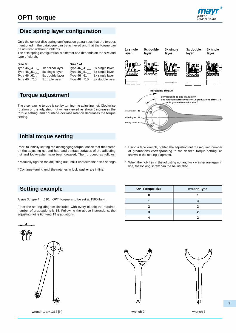
5x single 5x double 3x single 3x double 3x triplelayer layer layer layer layer
Only the correct disc spring configuration guarantees that the torquesmentioned in the catalogue can be achieved and that the torque canbe adjusted without problems. The disc spring configuration is different and depends on the size andtype of clutch.
Size 0: Size 1–4:Type 46_.415._ 1x helical layer Type 46_.41_._ 3x single layerType 46_.51_._ 5x single layer Type 46_.51_._ 3x single layerType 46_.61_._ 5x double layer Type 46_.61_._ 3x single layerType 46_.710._ 3x triple layer Type 46_.710._ 3x double layer
Disc spring layer configuration
The disengaging torque is set by turning the adjusting nut. Clockwiserotation of the adjusting nut (when viewed as shown) increases thetorque setting, and counter-clockwise rotation decreases the torquesetting.
Torque adjustment
Prior to initially setting the disengaging torque, check that the threadon the adjusting nut and hub, and contact surfaces of the adjustingnut and lockwasher have been greased. Then proceed as follows:
* Manually tighten the adjusting nut until it contacts the discs springs
* Continue turning until the notches in lock washer are in line.
Initial torque setting
A size 3, type 4__.610._ OPTI torque is to be set at 1500 lbs-in.
From the setting diagram (included with every clutch) the required number of graduations is 15. Following the above instructions, theadjusting nut is tightend 15 graduations.
Setting example
* Using a face wrench, tighten the adjusting nut the required numberof graduations corresponding to the desired torque setting, asshown in the setting diagrams.
* When the notches in the adjusting nut and lock washer are again inline, the locking screw can the be installed.
wrench 1 a = .368 [in] wrench 2 wrench 3
0
1
2
3
4
1
3
2
2
2
OPTI torque size wrench Type
increasing torque
corresponds to one graduationone rotation corresponds to 12 graduations sizes 1-4
or 24 graduations with size 0
lock washer 11
adjusting nut 10
locking screw 12

10
OPTI torque
®
powertransmission
sizeset screw
metric
dimension ”a“ dimension ”c“ dimension ”e“ DU disc
mm inch mm inch mm inch mm inch
Recommended set screw sizes and position of plate wheel sprocket
0
1
2
3
4
M4
M6
M6
M8
M8
3
4,5
4,5
6
6
0.118
0.177
0.177
0.236
0.236
5
7,5
7,5
10
10
0.197
0.295
0.295
0.394
0.394
6,5
9
9
12
12
0.256
0.354
0.354
0.472
0.472
1,5
1,5
1,5
2
2
0.059
0.059
0.059
0.079
0.079
sizeset screw dimension ”a“ dimension ”c“ dimension ”e“ DU disc
mm inch mm inch mm inch mm inch
Recommended set screw sizes and position (ANSI)
0
1
2
3
4
10-32 UNF
1/4-20 UNC
5/16-18 UNC
5/16-18 UNC
3/8-16 UNC
3
4.5
4.5
6
6
0,118
0.177
0.177
0.236
0.236
4,6
7,3
6,5
10
9,2
0.181
0.287
0.256
0.394
0.362
6,1
8,8
8
12
11,2
0.240
0.346
0.315
0.472
0.441
1,5
1,5
1,5
2
2
0.059
0.059
0.059
0.079
0.079
dim. shaft diameter bore H7
Tolerance chart for finish bore
mm
in
mm
in
mm
in
10 – 18
0.39 – 0.7
20 – 30
0.7 – 1.2
30 – 50
1.2 – 2
+ 0.0180
+ 0.00070
+ 0.0210
+ 0.00080
+ 0.0250
+ 0.0010
DIN 6885 (mm) ANSI (in.)
Standard keyways used
bore
17 – 22
23 – 30
31 – 38
39 – 44
45 – 50
51 – 55
bore
5/8 – 7/8
15/16 – 1 – 1/4
1 – 5/16 – 1 – 3/8
1 – 7/16 – 1 – 3/4
1 – 13/16 – 2
2 – 1/16 – 2 1/8
keyway
3/16 x 3/32
1/4 x 1/8
5/16 x 5/32
3/8 x 3/16
1/2 x 1/4
1/2 x 1/4
keyway
6 x 2,8
8 x 3,3
10 x 3,3
12 x 3,3
14 x 3,8
16 x 4,3

11
Limit switch Type 055.000.5 (mechanical operation)
®
powertransmission
Application
Monitoring of mechanical movements and final positions. Controlswitch for electronic and mechanical sequences. Measuring of axialdisengaging movements, for example in connection with EAS®-clutches.
Function
The pre positioned contact is unloaded by actuating the controllever: Open contacts 11-14 (21-24), close 11-12 (21-22).
Design
The micro switch fitted into an aluminium die cast housing isactuated by a control lever. Operation is only possible in onedirection. The limit switch is fastened with M4 cap screws via two screw-onbrackets attached diagonally.
Technical data
Contact type 1 change-over contact (special design: 2 change-over contacts)
Switching capacity 250 VAC / 15 A (with 2 contacts: 10A)24 VDC / 6 A60 VDC / 1,5 A250 VDC / 0,2 Amin. 12 VDC/10 mA
Contact material AgCdO 90/10Switching frequency max. 200 switching operations/minAmbient temperature -10 °C up to +85 °CProtection IP 54Weight 275 gSwitch travel setting By the adjusting screw (SW 7) arranged
laterally the zero shift is possible to right orleft by max. 5 mm
Switch travel Pre-travel min. 0,15 to 0,5 mm Over-travel: max. 10 mm, depending on
the zero shiftSpecial types On request different control lever lengths
as well as a design with 2 change-overcontacts are possible
Electrical connection
To be included whenordering, please state:
Order number:
Type
0 5 5 . 0 0 0 . 5
Dimensions (mm)

Wordwide representation
®
powertransmission
Great BritainMayr Transmissions Ltd.Valley Road, Business ParkKeighley, BD21 4LZWest YorkshireTel.: 0 15 35/66 39 00Fax: 0 15 35/66 32 [email protected]
ItalyMayr Italia S.r.l.Viale Veneto, 335020 Saonara (PD)Tel.: 0 49/8 79 10 20Fax: 0 49/8 79 10 [email protected]
FranceMayr France S.A.Z.A.L. du MinopoleBP 1662160 Bully-Les-MinesTel.: 03.21.72.91.91Fax: [email protected]
USAMayr Corporation4 North StreetWaldwickNJ 07463Tel.: 2 01/4 45-72 10Fax: 2 01/4 45-80 [email protected]
SingaporeMayr Transmission (S)Pte. Ltd. – Blk 133Jurong East Street 13Unit 03-291Singapore 600133 AseanTel.: 0065/65601230Fax: 0065/[email protected]
ChinaMayr ShanghaiRoom 608, No. 1277West Zhongshan Road,Conch Building,200051 Shanghai, ChinaTel.: 021/62953138Fax: 021/[email protected]
KoreaMayr Korea60-11, Woongnam-DongROK ChangwonRep. of KoreaTel.: 055/262-4024Fax: 055/[email protected]
Headquarters Chr. MayrGmbH + Co. KGEichenstraße 187665 MauerstettenTel.: 49-83 41/8 04-241Fax: 49-83 41/[email protected]://www.mayr.de
AustriaBenelux StatesBrazilCanadaCzech RepublicDenmarkFinlandGreece
your reliable partner
TaiwanGerman Tech Auto Co. Ltd.No. 58, Wu Chuan RoadWu-Ku Industrial ParkTaipei Hsien, TaiwanTel.: 02/22990237Fax: 02/[email protected]
IndiaNational EngineeringCompany (NENCO)J-225, M.I.D.C. BhosariPune 411026Tel.: 0202/7474529Fax: 0202/[email protected]
AustraliaTransmission Australia Pty. Ltd.22 Corporate Ave,3178 Rowville, VictoriaAustralienTel.: 039/755 4444Fax: 039/755 [email protected]
South AfricaTorque TransferPrivate Bag 9Elandsfontein 1406Tel.: 011/3458000Fax: 011/[email protected]
HongkongHungaryIndonesiaIsraelMalaysiaNew ZealandNorwayPhilippines
PolandRomaniaRussiaSlovakiaSloveniaSpainSwedenThailand
Note:If a country is notshown, please referto headquarters orour web site to beadvised of the nearest responsibleagent.
SwitzerlandMayr Kupplungen AGTobeläckerstrasse 118212 Neuhausen
am RheinfallTel.: 0 52/6 74 08 70Fax: 0 52/6 74 08 [email protected]
Machine Tool Applications in ChinaDTC. Co.Ltd., Block 5th, No. 1699,East Zhulu Road,201700 Shanghai, ChinaTel.: 021/59883978Fax: 021/[email protected]
JapanSumitomo HI-PTC Sales Co., Ltd.3-5-8, Kandakaji-Cho,Chiyoda-KuTokyo J101-0045Tel.: 03/52563091Fax: 03/[email protected]
Turkey
21/1
1/20
05IM