Opportunities of Hybridization of CSP Plants by Biomass ... Gomez... · * CS=Solar Field;...
31
Chemical and Environmental Engineering Department Bioenergy Group Opportunities of Hybridization of CSP Plants by Biomass Conversion Prof. Alberto Gómez Barea ([email protected]) Fluidized Bed Conversion of Biomass and Waste (IEA FBC and IEA Bioenergy Task 33) 24-25 October 2017. Skive (Denmark)
Transcript of Opportunities of Hybridization of CSP Plants by Biomass ... Gomez... · * CS=Solar Field;...

Chemical and Environmental Engineering Department
Bioenergy Group
Opportunities of Hybridization of CSP Plants by Biomass Conversion
Prof. Alberto Gómez Barea ([email protected])
Fluidized Bed Conversion of Biomass and Waste
(IEA FBC and IEA Bioenergy Task 33)
24-25 October 2017. Skive (Denmark)
AGB. 24 Oct 17. US
Bioenergy Group
Chemical and Environmental Engineering Department
1
1. Introduction to CSP
2. Concept of Hybridization of CSP with Biomass
3. Hybridization strategies
4. Commercial experience
5. Comparative analysis: Hybrid vs Standalone CSP
6. Biomass conversión options: combustion vs gasification
7. Hybrid options based on fluidized bed tecnologies
Contents

AGB. 24 Oct 17. US 2
Receiver
Thermal Energy Storage
Power Block
Alternate Energy Source
Concentrated Solar Thermal Power (CSP) Plant

AGB. 24 Oct 17. US 3
Parabolic Trough(C ≈ 80, T ≈ 400 ºC)
Linear Fresnel Reflector(C ≈ 50, T ≈ 300 – 500 ºC)
Parabolic Dish(C ≈ 2500, T ≈ 800 ºC)
Power Tower(C ≈ 600, T ≈ 102 − 103 K)
CSP Technologies
CSP in Spain

AGB. 24 Oct 17. US
• Solar to power needs to provide dispatchability.
Two options:
1. Fuel-based backup (hybridization)
2. Thermal Energy Storage (TES)
• CSP can ideally adapted for both options
• CSP competes with PV with storage (batteries) to guarantee dispatchability
(PV is cheaper without storage but more expensive with batteries, which should be actually the basis for comparison)
4
Solar to Power: The potential of CSP

AGB. 24 Oct 17. US
SOLAR FIELD
HTF EXCH
ANGER
POWER
ISLA
ND
HEAT
EXC
HANGER
HEAT TANKSTORAGE
COLD TANKSTORAGE
HEAT
SUPP
ORT
Fuel
Options of dispatchability
HYBRIDIZATION WITH BIOMASS KEEP THE OVERALL SYSTEM RENEWABLE
AGB. 24 Oct 17. US 6
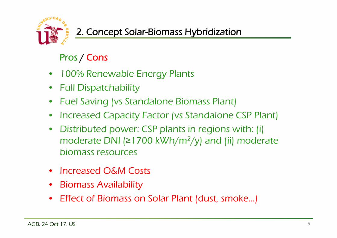
2. Concept Solar-Biomass Hybridization
• 100% Renewable Energy Plants
• Full Dispatchability
• Fuel Saving (vs Standalone Biomass Plant)
• Increased Capacity Factor (vs Standalone CSP Plant)
• Distributed power: CSP plants in regions with: (i) moderate DNI (≥1700 kWh/m2/y) and (ii) moderate biomass resources
• Increased O&M Costs
• Biomass Availability
• Effect of Biomass on Solar Plant (dust, smoke…)
Pros / Cons
AGB. 24 Oct 17. US
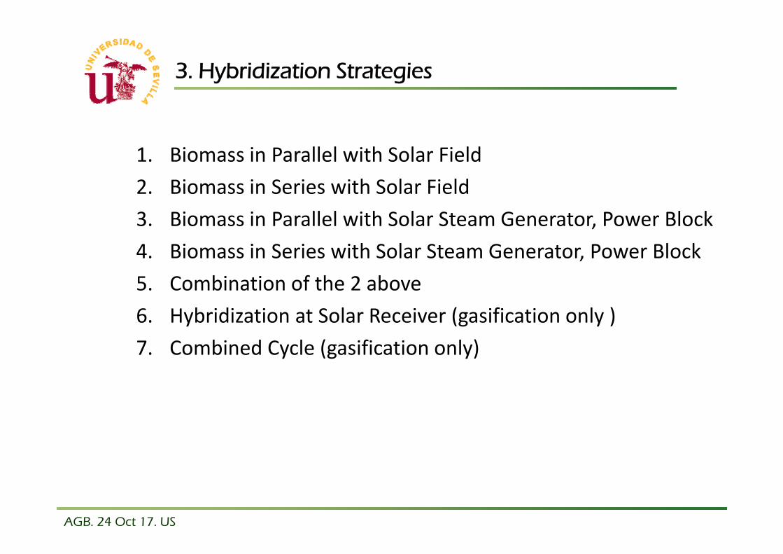
3. Hybridization Strategies
1. Biomass in Parallel with Solar Field2. Biomass in Series with Solar Field3. Biomass in Parallel with Solar Steam Generator, Power Block4. Biomass in Series with Solar Steam Generator, Power Block5. Combination of the 2 above6. Hybridization at Solar Receiver (gasification only )7. Combined Cycle (gasification only)

AGB. 24 Oct 17. US
Biomass Boiler in parallel to Solar Field (C1)
*CS=SolarField;CG=BiomassConversor;INT=HeatExchanger(SteamGenerator);
CP=PowerBlock
INT CPCGCS
AporteGasBiomassSupply

AGB. 24 Oct 17. US
Biomass Boiler in series to Solar Field (C2)
*CS=SolarField;CG=BiomassConvertor;INT=HeatExchanger(SteamGenerator);
CP=PowerBlock
INT CPCS
CG
AporteGasBiomassSupply
AGB. 24 Oct 17. US
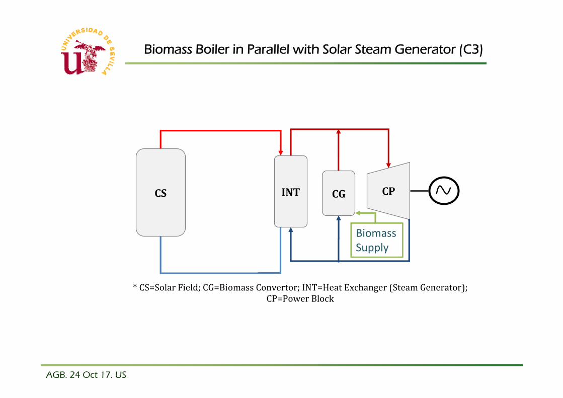
Biomass Boiler in Parallel with Solar Steam Generator (C3)
*CS=SolarField;CG=BiomassConvertor;INT=HeatExchanger(SteamGenerator);
CP=PowerBlock
CP
AporteGas
CGCS INT
BiomassSupply

AGB. 24 Oct 17. US
Biomass Boiler in series to Solar Steam Generator (C4)
*CS=SolarField;CG=BiomassConvertor;INT=HeatExchanger(SteamGenerator);
CP=PowerBlock
CP
CG
AporteGasINTCSBiomassSupply

AGB. 24 Oct 17. US
Biomass Boilers in parallel + series to Solar Steam Generator (C5)
*CS=SolarField;CG=BiomassConvertor;INT=HeatExchanger(SteamGenerator);
CP=PowerBlock
INT CPCS CG2
AporteGas
CG1
AporteGasBiomass Supply
BiomassSupply

AGB. 24 Oct 17. US
Hybrid Receiver (C6)
*CS=SolarField;CG=BiomassConvertor;INT=HeatExchanger(SteamGenerator);
CP=PowerBlock
CPRS AporteGas INTBiomassSupply(Gas)
AGB. 24 Oct 17. US
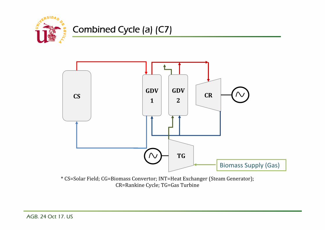
Combined Cycle (a) (C7)
*CS=SolarField;CG=BiomassConvertor;INT=HeatExchanger(SteamGenerator);
CR=RankineCycle;TG=GasTurbine
GDV1
CRCS
AporteGasTG
GDV2
Biomass Supply (Gas)

AGB. 24 Oct 17. US
Combined Cycle (b) (C8)
*CS=SolarField;CG=BiomassConvertor;INT=HeatExchanger(SteamGenerator);
CR=RankineCycle;TG=GasTurbine
CRCS
AporteGas
TG
SC
GDV
Biomass Supply (Gas)

AGB. 24 Oct 17. US
Comparison of Configurations
FEATURES C1 C2 C3 C4 C5 C6 C7 C8Off‐SunGeneration X ‐ X ‐ X X X XIncreasePowerBlockEfficiency ‐ X ‐ X X ‐/X ‐ XDecoupleSolarandBiomassResources X ‐ X ‐ ‐ X/‐ X ‐EasyIntegrationinCurrentSTEPlants X ‐ X ‐ ‐ X/‐ ‐ ‐IncreaseBiomasstoElectricEfficiency ‐ ‐ X X X X/‐ X XLowTechnologyRisk X X X X X ‐ ‐ ‐StableSolarreceiveroperation ‐ ‐ ‐ ‐ ‐ X/‐ ‐ ‐

AGB. 24 Oct 17. US
First CSP-Biomass Power Plant: Borges Termosolar, Lleida, Spain
17
• Solar field: 183 120 m2 aperture area
• Back-up block: 20 MWth biomass boiler, 20 MWth dual biomass and natural gas boiler,10 MWth natural gas auxiliary boiler
• Electric block: 22,5 MWe steam turbine generator
44136
47322
10167
Solar (MWh/y) Biomass (MWh/y) Natural Gas (MWh/y)
4. Commercial experience
AG5AG6
AG7

Folie 18
AG5 Alberto Gomez; 22.10.2017
AG6 Alberto Gomez; 22.10.2017
AG7 Alberto Gomez; 22.10.2017

AGB. 24 Oct 17. US
Borges: Comparison with Standalone CSP and PV
18
Borges:22,5 MWe
102 000 MWh/y
Standalone CSP:50 MWe
110 000 MWh/y
Comparison criteria: sameelectrical production

AGB. 24 Oct 17. US
Borges: some data
19
Energy production with very low or no solar radiation
Designed to achieve 50% turbine’s workload at nights,avoiding sharply efficiency decreases. Turbineefficiency 37% at full load
Biomass consumption: 66 000 t/y (45% moisture)
DNI: 1800 kWh/m2/y
6500 h/y operation ⟶ CP: 0,74
Cost: 153 M€

AGB. 24 Oct 17. US 20
• Lower investment cost (CAPEX):
Biomass StandaloneCAPEX < CSP-BiomassCAPEX < CSP Standalone CAPEX
• Higher capacity factor (CF)
CSP Standalone CF < CSP-BiomassCF < Biomass StandaloneCF
0
1000
2000
3000
4000
5000
6000
7000
8000
CSP + 4h TES CSP + 8h TES CSP + 12h TES CSP‐Biomass
Investmen
t costs (U
S$/kW)
0
0,1
0,2
0,3
0,4
0,5
0,6
CSP + 4h TES CSP + 8h TES CSP + 12h TES CSP‐Biomass
Capacity Factor
5. CSP-biomass hybridization vs Standalone CSP plants

AGB. 24 Oct 17. US
CSP-biomass hybridization vs Standalone CSP plants
21
• Higher dispatchability
• Lower solar multiple (less solar field’s area required)
• Higher power generation
• Lower LCOE
• Higher thermodynamic efficiency due to continuous turbine operation at higher loads
CSP+TES & CSP-Biomassmodelling
180 GWh PowerGeneration

AGB. 24 Oct 17. US 22
Capital requirements profitable even in small and medium sized plants (if compared with CSP standalone)
CSP-biomass hybridization vs Standalone CSP plants

AGB. 24 Oct 17. US 23
6. Biomass conversion options
• Enables high-efficient hybridization (hybrid receiver, CC)
• More flexibility in “ready-to-hybridized” applications:
Easier performance during transients
Syngas storage
More efficient and controlled burning
• Enables syngas cleaning (waste feedstocks)
Gasification (vs Combustion)

AGB. 24 Oct 17. US
• FB convertor (boliler and gasifier) (FBC)
• FB heat exchangers (FBEx)
• FB Thermal Energy Storage (FB-TES)
• Combinations
24
7. Potential of FB technology in hybridization

AGB. 24 Oct 17. US
FBEx: Solid Particle Receiver-based CSP system (NREL)
25

AGB. 24 Oct 17. US
SandTES: Active fluidization energy storage (TUV)
26
AGB. 24 Oct 17. US 27
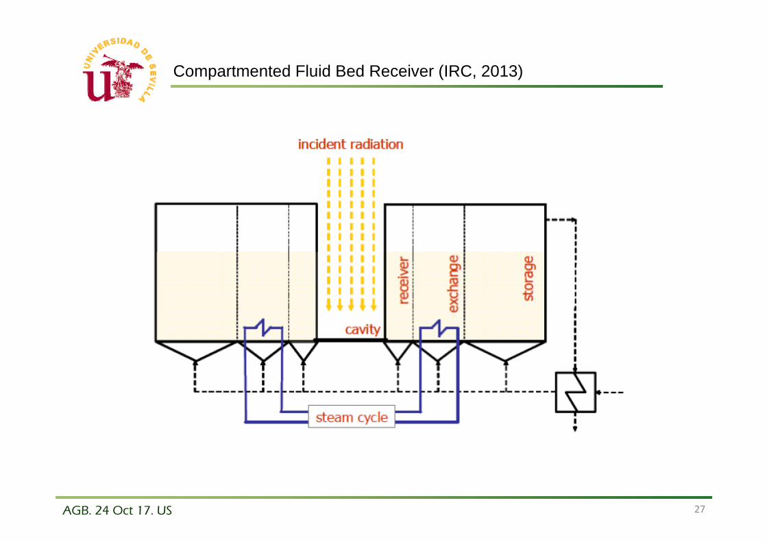
Compartmented Fluid Bed Receiver (IRC, 2013)

AGB. 24 Oct 17. US 28
1. Solar-biomass hybridization is a promising concept (only one plant at commercial scale)
2. Storage or backup fuel is necessary to garantee dispatchability. CSP-biomass hybrid is more competitive tan PV with batteries
3. Different alternatives of CSP hybridization with biomass, both based on combustion and gasification of biomass
4. Integration in current parabolic trough technology is straightforward and seems to be feasible
5. Challenges for advanced, more efficient concepts remain huge. Development of gasification seems to play a key role
6. Advanced design in development for both TES and hybrid integration
Conclusions

AGB. 24 Oct 17. US
Thank youContact: Alberto Gómez Barea ([email protected])
IEA FBC and IEA Bioenergy Task 33. Fluidized Bed Conversion of Biomass and Waste 24‐25 Oct 2017. Skive (Denmark)
6. Biomass conversion options: Gasification vs Combustion