Ophthalmoscope / Retinoscope / Otoscope...ensure that you get many years of trouble free service....
37
Next Next Ophthalmic and Diagnostic Instruments Ophthalmoscope / Retinoscope / Otoscope Instructions for use
Transcript of Ophthalmoscope / Retinoscope / Otoscope...ensure that you get many years of trouble free service....
NextNext
Ophthalmic and Diagnostic InstrumentsOphthalmoscope / Retinoscope / Otoscope
Instructions for use

NextBack 2
Contents Page
1. Copyrightandtrademarks ................................................... 3
2. Introduction ........................................................................... 4
3. Symbols .................................................................................. 5
4. Safety ..................................................................................... 6
• Deviceclassification
• Warnings
• Cautions
• Safetyconsiderations .................................................... 10
5. DiagnosticInstrumentheads
• Ophthalmoscopemodels .............................................. 11
• Lenswheels ................................................................... 12
• Lensranges
• Graticulesandgraticulecontrol
• Filtersandfiltercontrol ................................................ 13
• Retinoscopemodels ...................................................... 14
• Otoscopemodels ........................................................... 15
• Bulbreplacement .......................................................... 17
6. Instrumenthandles ............................................................. 18
• Handlemodels
• Handleidentification .................................................... 20
• Inserting/replacingbatteries
Page
• Upgradingtorechargeablehandles ............................ 20
• Batteryconditioning/charging ................................... 21
7. GenMedWallUnit ............................................................... 22
• Wallmounting
• Wallmountingtemplate .............................................. 23
• Powersupplyassembly ................................................. 24
• Connecting/securingheads ........................................ 25
• UsingtheGenMedWallUnit ...................................... 26
• Dispos-A-Spec
8. LithiumChargers ................................................................. 27
• LithiumMiniCharger
• LithiumDoubleCharger
• Chargingcycle
9. Cleaninginstructions .......................................................... 28
10. Specificationsandelectricalratings .................................. 29
• Electricalspecifications
• Transport,storageandoperation
11.AnnexI–EMCstatementandguidelines ......................... 30
12. Sparepartsandaccessories ................................................ 35
13.Warranty .............................................................................. 36
14.Contactanddisposalinformation ..................................... 37
Click on the headings above to go directly to that section.
Usethebuttonsontherighttonavigatethedocument.
Clicking‘Home’fromanypagebringsyoubacktothiscontentspage.

NextHome Back 3
1. Copyright and trademarks
The information contained within this manual must not be
reproduced in whole or in part without the manufacturer’s
prior written approval.
As part of our policy for continued product development we
reserve the right to make changes to specifications and other
information contained in this document without prior notice.
The products listed opposite are registered trademarks of
Keeler Ltd 2012
Copyright © Keeler Limited 2012
Published in the UK 2012
Ophthalmoscopes:Pocket, Professional, Specialist, Standard
Retinoscopes:Professional Combi, Spot, Streak
Otoscopes:Deluxe, Fibre-Optic, Pocket, Professional, Standard
Handles:C-size, Pocket, Slimline, GenMed Wall Unit
Chargers:Lithium Duo Charger, Lithium Mini Charger, C-size NiCad Duo

NextHome Back 4
2. Introduction
Thank you for purchasing your Keeler diagnostic
instrument.
We have taken the greatest care in the design,
development and manufacture of this product to
ensure that you get many years of trouble free
service. However, it is important that you read the
descriptions, installation and operating instructions
carefully prior to installing or using your new
instrument.
Please read and follow these instructions carefully.
NextHome Back 5
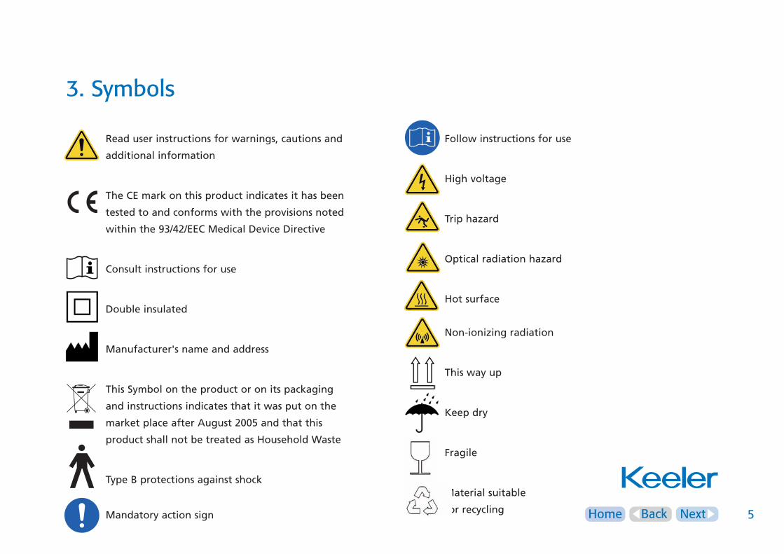
3. Symbols
Read user instructions for warnings, cautions and
additional information
The CE mark on this product indicates it has been
tested to and conforms with the provisions noted
within the 93/42/EEC Medical Device Directive
Consult instructions for use
Double insulated
Manufacturer's name and address
This Symbol on the product or on its packaging
and instructions indicates that it was put on the
market place after August 2005 and that this
product shall not be treated as Household Waste
Type B protections against shock
Mandatory action sign
Follow instructions for use
High voltage
Trip hazard
Optical radiation hazard
Hot surface
Non-ionizing radiation
This way up
Keep dry
Fragile
Material suitable
for recycling

NextHome Back 6
4. Safety
Device classificationCE Regulation 93/42 EEC: Class I
FDA: Class II
Carefully read this Instruction Section before using your Keeler
product. For your own safety and that of your customers
observe all cautionary information provided in this section. The
following information is intended to highlight potential safety
hazards that can be associated with misuse, or damage.
Warnings and cautions - General
Warning
• Check your Keeler product for signs of transport / storage
damage prior to use
• Do not use if the product is visibly damaged, and periodically
inspect for signs of damage
• Do not use in the presence of flammable gases / liquids, or in
an oxygen rich environment
• This product should not be immersed in fluids
Switch off the electrical supply and disconnect from the
mains electrical supply before cleaning and inspection
• If the product emits a strange odour, heat or smoke, stop use
immediately. The continued use of a damaged product or part
may cause injuries
• US Federal law restricts this device to sale by or order of a
physician or practitioner
Caution
• Use only genuine Keeler approved parts and accessories or
device safety and performance may be compromised
• Use only Keeler approved batteries, chargers and power
supplies as per the accessories listed in section 12.

NextHome Back 7
4. Safety
Warnings and cautions – General (cont’d)• The product has been designed to function safely when at an
ambient temperature between +10°C and +35°C
• Keep out of the reach of children
• To prevent condensation from forming, allow instrument to
come to room temperature before use
• For indoor use only (protect from moisture)
• There are no user serviceable parts inside. Contact authorised
service representative for further information
• Ensure device is securely held in docking station to minimise
risk of injury or damage to equipment
• Follow guidance on cleaning / routine maintenance to prevent
personal injury / damage to equipment
• Failure to carry out recommended routine maintenance as per
the instructions in this IFU may reduce the operational lifetime
of the product
• At product end of life dispose of in accordance with local
environmental guidelines (WEEE)
Chargers
Do not fit mains power adapter into a damaged mains
outlet socket
Route power cords safely to eliminate risk of tripping
or damage to equipment
Only Keeler handles with a red base can be used in the Keeler
Lithium Chargers. Do not try to insert a Keeler handle with a
blue base into the Keeler Lithium Chargers. Refer to Keeler
handle and bulb identification.
NextHome Back 8
4. Safety
Diagnostic Instruments• When connecting instrument heads to handles please check
that the voltage of the bulb in the instrument corresponds
with the voltage of the handle.
• Care should be taken when fitting heads to handles not to
trap skin between parts
• Please ensure that the control is in the off position when the
examination has been completed.
• Keeler Professional Retinoscopes contain strong magnets.
Pacemakers and magnetically stored data will be affected or
damaged by magnets.
• Strong magnetic fields may influence or distort sensitive
electronic or mechanical test instruments. Very sensitive
devices may even be destroyed. Always keep magnets at a
safe distance from such devices.
• Do not use Keeler Retinoscopes in ambient temperatures
above 30°C.
• Disposable speculae should not be used for insufflation
testing
• Plastic reusable Speculae will degrade if exposed to ultra-
violet light, dry heat or gamma irradiation. These methods of
sterilization must not be used.
Batteries and bulbs• Do not use a battery that is deformed, leaking, corroded or
visually damaged. Handle a damaged or leaking battery with
care. If you come into contact with electrolyte, wash exposed
area with soap and water. If it contacts the eye, seek medical
attention immediately
• Ensure battery orientation is correct, or personal injury /
damage to equipment may occur
• Do not mix battery types
• Do not attempt to charge Non-Rechargeable batteries
• Do not charge battery in an environment where the
temperature may exceed 40˚C or fall below 0˚C
NextHome Back 9
4. Safety
Batteries and bulbs (cont’d)• When replacing rechargeable cell, turn handle off and insert
new cell. Replace bottom cap, and place handle into charging
well.
• If a short circuit occurs, reactivate the battery by placing the
handle in the charger until the LED lashes. This is a built in
protection device to protect the battery from damage
• Dry cell batteries should be removed if your instrument is not
to be used for long periods
• Do not disassemble or modify the battery. There are no
serviceable parts inside
• Do not dispose of battery in fire, puncture or short circuit
• Dispose of batteries in line with local environmental
regulations
• Tape over battery contacts to avoid short circuiting during
disposal
After removal of the battery do not touch the battery
contacts and the patient simultaneously
Note:LithiumIonbatteriescontainnotoxicheavymetals
suchasmercury,cadmiumorlead
Do not exceed maximum recommended exposure time
• Always ensure that the handle rheostat is turned off before
fitting an instrument head or changing a bulb
Bulbs / LED’s can reach high temperatures in use – allow
to cool before handling
• Care should be taken when handling halogen bulbs. Halogen
bulbs can shatter if scratched or damaged
After removal of the bulb / LED do not touch the bulb /
LED contacts and the patient simultaneously
Refertotheinstructionsonpage17forbulbreplacement.

NextHome Back 10
4. Safety
Safety considerationsIt is well established that exposure of the eye to intense light
sources for extended periods of time poses a risk of retinal
photic injury. Many ophthalmic instruments illuminate the eye
with intense light. The decision about the intensity of the light
level to use in any procedure must be made on a case to case
basis. In each case, the clinician must take a risk benefit
judgement about the intensity of light to be used. Use of
insufficient intensity may result in inadequate visualization and
in adverse effects more serious than retinal photic damage.
Further, despite all efforts taken to minimise the risk of retinal
damage, damage may still occur. Retinal photic injury is a
possible complication of the need to use bright light to clearly
visualize ocular structure during delicate ophthalmic surgical
procedures.
While no visible retinal lesions have been identified for
ophthalmic instruments, it is recommended that illumination
levels be set to the minimum level necessary to perform the
diagnostic function. Young children and persons with diseased
eyes may be at a higher risk. The risk may also be increased if
the person being examined has had any exposure with the same
instrument or any other ophthalmic instrument using an intense
visible light source during the previous 24 hours. This will apply
particularly if the eye has been exposed to retinal photography.
CAUTION-Thelightemittedfromthisinstrumentispotentially
hazardous.Thelongerthedurationofexposure,thegreaterthe
riskofoculardamage.Exposuretolightfromthisinstrument
whenoperatedatmaximumintensitywillexceedthesafety
guidelineafter3minutes.

NextHome Back 11
Standard
Practitioner / Professional
Specialist
AuxiliaryLensWheel
LensWheel
Pupilometer
LensWheel
GraticuleandFilterControl
LensWheel
AuxiliaryLensWheel
FilterControl
GraticuleControl
5. Instrument heads - Ophthalmoscopes
GraticuleandFilterControl

NextHome Back 12
5. Instrument heads - Ophthalmoscopes
Lens WheelThe lens wheel is rotated to select the required lens. Lens
powers are displayed in the viewing window as follows:
Black = (+) power lenses
Red = (-) power lenses
Auxiliary lens wheelSwings in +/- 20 in one Dioptre step* (*Professionalonly).
Specialist Auxiliary lens wheelRotate to align +10, +15, +30/ -10, -15, -30 Dioptre lenses.
Lens rangesSpecialist
+44D to –45D in single Dioptre steps
Professional
+29D to –30D in single Dioptre steps
PractitionerandStandard
+40D to –25D
+20D to –20D
Graticule ControlThe graticule control is used to select the required beam for
examination. The choice of graticules is as follows.
WideAngle
Illuminates the largest area of fundus for the best
possible general diagnosis through a dilated pupil.
Intermediate
Permits easier access through an undilated pupil in
peripheral examination. Particularly useful in paediatric
examination.
Macular
Designed specifically for viewing the macular area of
the fundus. Reduces pupillary reaction and improves
patient comfort.
Slit
Used primarily to determine retinal elevations and
depressions but may also be used to assess anterior
chamber depth.

NextHome Back 13
5. Instrument heads - Ophthalmoscopes
Graticule Control (cont’d) Glaucoma
Projects a graticule onto the retina to assess the optic
disc/cup ratio as an aid to glaucoma diagnosis and
monitoring.
FixationCross
Projects a graticule on to the retina for assessment of
the degree and direction of eccentric fixation. This is
particularly useful when examining children.
TheGraticuleRangeforeachophthalmoscopeisasfollows:
Specialist
Professional
Practitioner
Standard
Filter Control*The filter control is used to select the required filter.
(*Professional/Practitioner/Standardonly.)
Filter Applications RedFree(Greenfilter)
Is used to examine the blood vessels in fine detail. The
green filter blocks red rays showing blood vessels as
black against a dark green background. This filter is particularly
useful for diabetic retinopathy.
CobaltBlue*
Is used in conjunction with flourescein dye for the
detection and examination of corneal scars and abrasions.
(*PractitionerandSpecialistonly).
Pupillometer*Hold the pupillometer adjacent to the patients eye to
estimate pupil size. 1=1mm. The range is 1mm to 8mm.
(*AppliestoSpecialistonly.)

NextHome Back 14
BrowRest
FocussingandAxisControl
5. Instrument heads - Retinoscopes
Professional Combi Retinoscope
Focussing and axis control (Streak)The vergence is altered by sliding the focussing control up and
down as indicated. In the top position the effect is a concave
mirror. Mid position produces a streak behind the patient. The
mid position is used to determine the presence and axis of any
astigmatism. In the bottom position the effect is a divergent
plane mirror effect. Refraction is normally performed between
the mid position and the bottom position. The focussing and
axis control can be rotated continuously in any direction.
Focussing and axis control (Spot)The vergence is altered by sliding the focussing control up and
down as indicated. For all positions the effect is a plane mirror
effect.
Brow RestThe Keeler retinoscope is supplied with a choice of brow rests to
accommodate spectacle wearers. To interchange the brow rest
disconnect and attach as indicated.
Aperture Control The aperture control has two positions. To change from the
large to the small aperture slide the control from left to right as
indicated.
Note: Handheld diagnostic instruments can become hot
during use and charging
ApertureControl
NextHome Back 15
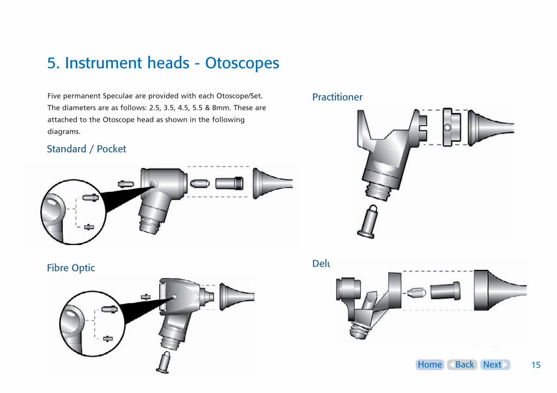
5. Instrument heads - Otoscopes
Five permanent Speculae are provided with each Otoscope/Set.
The diameters are as follows: 2.5, 3.5, 4.5, 5.5 & 8mm. These are
attached to the Otoscope head as shown in the following
diagrams.
Standard / Pocket
Fibre Optic
Practitioner
Deluxe

NextHome Back 16
5. Instrument heads - Otoscopes
Disposable Speculae*Disposable speculae can be fitted to the Standard, Practitioner,
Fibre Optic and Pocket Otoscopes.
The disposable speculae is attached as shown on the previous
page.
Pneumatic Testing*An insufflation tube can be fitted to your Otoscope to enable
you to carry out pneumatic testing.
For Practitioner, Standard, Pocket & Fibre Optic Otoscopes attach
the insufflation adaptor into port. The insufflation tube can
then be attached to this.
An Insufflation adaptor is also available for Practitioner as
shown on the previous page.
Minor surgical ProceduresShould you wish to use surgical instruments such for minor
procedures the following notes may be of assistance.
Standard and Pocket OtoscopesThe magnifier can be removed to allow the introduction of
surgical instruments.
Fibre Optic/PractitionerThe Fibre Optic magnifier can be moved to one side or removed
completely to aid the introduction of surgical instruments.
Deluxe OtoscopeThe Deluxe magnifier may be swung to the side to aid the
introduction of surgical instruments. The magnifier can also be
rotated clockwise to bring the focus closer to the end of the
specula.

NextHome Back 17
5. Instrument heads
Bulb replacement Bulbs / LED’s can reach high temperatures in use – allow
to cool before handling
• Always ensure that the handle rheostat is turned off before
fitting an instrument head or changing a bulb
• Care should be taken when handling halogen bulbs. Halogen
bulbs can shatter if scratched or damaged
• After removal of the bulb / LED do not touch the bulb / LED
contacts and the patient simultaneously
• Keeler bulbs can only be used in the instrument for which
they are designed – refer to part number list in section 12
• Ensure the replacement bulb is the correct voltage. See base
of bulb
• Blue = 2.8v for dry cell battery handles
• Red = 3.6v for rechargeable handles
• Black = LED
• Loosen the set screw securing the instrument
head to the handle (GenMed Wall Unit only)
• Remove the head by holding it horizontally with one hand
while rotating the handle counterclockwise with the other
• Take care to ensure the battery / bulb does not drop out when
the head and handle are separated
• Remove the faulty bulb and dispose of in accordance with
local environmental regulations
• Replace the bulb with one of the correct voltage and type.
Ensure that the location key is aligned with the aperture in
the instrument head
• Refit the handle to the head by rotating it clockwise while
horizontal. If required, secure the head in
place with the set screw provided
(GenMed Wall Unit only)
NextHome Back 18
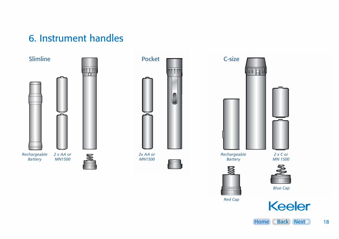
6. Instrument handles
2xAAorMN1500
RechargeableBattery
2xAAorMN1500
Slimline Pocket C-size
RechargeableBattery
RedCap
BlueCap
2xCorMN1500

NextHome Back 19
6. Instrument handles
Connection of the instrument headsto the handleThe connection between the instrument
head to the handle is a screw thread. To
connect our instrument head connect as shown
and rotate in clockwise direction. Ensure the
connection between the head and handle
is positive.
CompatibilityThe Keeler Specialist, Professional,
Standard and Practitioner Ophthalmoscopes and
Keeler Retinoscopes are compatible with Keeler 2.8v and 3.6v
Keeler handles.
On / Off brightness controlTo switch the instrument on, rotate the brightness control as
indicated to the right.
To switch off the instrument, rotate the brightness control as
indicated to the left.
Keeler C sizes Handles have a power indicator. This will show if
the instrument is on or off.
Off
Silver=off Red=on
HalfOn On
NextHome Back 20
6. Instrument handles
Handle IdentificationKeeler C size and pocket handles are colour coded to allow you
to distinguish between a dry cell battery handle (2.8v) and a
rechargeable handle (3.6v).
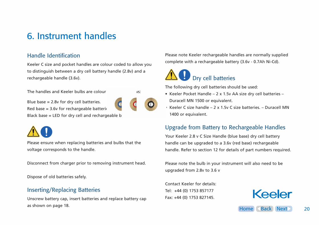
The handles and Keeler bulbs are colour coded as follows:
Blue base = 2.8v for dry cell batteries.
Red base = 3.6v for rechargeable batteries.
Black base = LED for dry cell and rechargeable batteries.
Please ensure when replacing batteries and bulbs that the
voltage corresponds to the handle.
Disconnect from charger prior to removing instrument head.
Dispose of old batteries safely.
Inserting/Replacing BatteriesUnscrew battery cap, insert batteries and replace battery cap
as shown on page 18.
Please note Keeler rechargeable handles are normally supplied
complete with a rechargeable battery (3.6v - 0.7Ah Ni-Cd).
Dry cell batteriesThe following dry cell batteries should be used:
• Keeler Pocket Handle – 2 x 1.5v AA size dry cell batteries –
Duracell MN 1500 or equivalent.
• Keeler C size handle – 2 x 1.5v C size batteries. – Duracell MN
1400 or equivalent.
Upgrade from Battery to Rechargeable HandlesYour Keeler 2.8 v C Size Handle (blue base) dry cell battery
handle can be upgraded to a 3.6v (red base) rechargeable
handle. Refer to section 12 for details of part numbers required.
Please note the bulb in your instrument will also need to be
upgraded from 2.8v to 3.6 v
Contact Keeler for details:
Tel: +44 (0) 1753 857177
Fax: +44 (0) 1753 827145.

NextHome Back 21
6. Instrument handles
Battery charging Do not attempt to charge non-rechargeable
batteries
Battery ConditioningYour Keeler rechargeable batteries need to be conditioned to
ensure you achieve the maximum life from the product. Follow
the conditioning instructions as indicated.
Step1
Fully charge your new Keeler rechargeable battery. This will take
approximately 15 hours.
Step2
Use the instrument WITHOUT RECHARGING UNTIL THE BATTERY
IS COMPLETELY EMPTY.
Step3
Once empty recharge the battery until full. This will take
approximately 15 hours.
Repeat steps 1, 2 and 3 three times, i.e. fully charge and
discharge the battery three times to complete the conditioning
process. Once you have conditioned your batteries as described
above you may place your instrument in the charger when not
in use between examinations.
Charger Compatibility Keeler Rechargeable Handles can be used in the
following Keeler chargers only:
• Keeler Mini charger
• Keeler Duo charger
Note: Handheld diagnostic instruments can become hot
during use and charging

NextHome Back 22
7. GenMed Wall Unit – wall mounting
Wall mountingCheck the distance
from the wall socket to
the intended mounting
position.
For the Gen Med Wall Units drill two holes Ø6mm x 55mm deep
and 110mm apart.
For the Dispenser Unit drill an additional two holes 249mm below
the existing holes using the template on the following page.
Secure the GenMed Wall Unit and Dispenser Unit as
shown below:
1.8m MAX
ø6mm
ø6mm
55mm

NextHome Back 23
7. GenMed Wall Unit and Dispenser mounting template
THIS
WAY
UP
WALL U
NIT AN
DD
ISPENSER
TEMPLATE
Scale 1:1 Do not scale
249mm
110mm

NextHome Back 24
7. GenMed Wall Unit – power supply assembly
Set PlugReplace the blanking plate with the appropriate mains plug
adaptor if required, or use IEC 60320 TYPE 7 connector
(not supplied).
IEC60320TYPE7connector
ConnecttoGenMedWallUnit

NextHome Back 25
7. GenMed Wall Unit
Pleasenote:
This equipment may be affected by electromagnetic
interference.
Other electrical equipment in the close vicinity may also
be affected by the GenMed Wall Unit.
If such effects are suspected, switch off the offending
equipment.
Connecting your instrument head to the wall unit handleThe instrument head should be screwed
positively onto the handle as shown.
As an additional security measure,
instrument heads may be locked onto
Keeler cord handles by tightening
the built in screw with the hexagonal
key provided.

NextHome Back 26
7. GenMed Wall Unit
To use the required instrument, remove the relevant handle from
its cradle as shown.
A yellow light (LED) will illuminate when a cord handle is
removed from its cradle. This will occur whether or not an
instrument head is fitted.
When the instrument is no longer required always ensure that
the handle is returned correctly to its cradle and that the LED
goes out.
Only one handle can be used at a time. Replace the handle
before using the other instrument.
Refer to the instructions in section 5 for information on the
controls and operation of Ophthalmoscope, Otoscope and
Retinoscope heads.
Dispos-A-SpecTo dispense a speculum, simply grasp the end of the required
speculum and gently pull vertically. When a dispenser tube is
empty, reorder speculum using the order form EP59-48483.
Remove the lid from the unit and refill the required tube.
PULL
NextHome Back 27
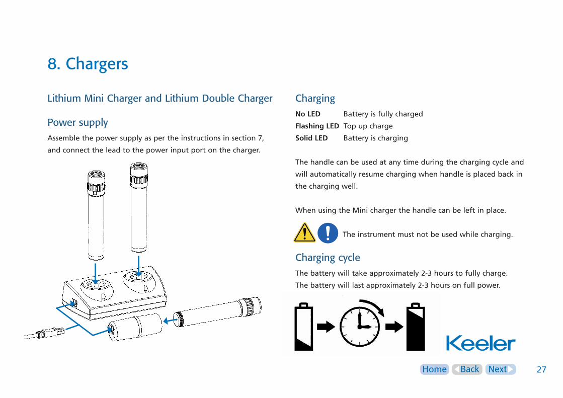
8. Chargers
Lithium Mini Charger and Lithium Double Charger
Power supplyAssemble the power supply as per the instructions in section 7,
and connect the lead to the power input port on the charger.
ChargingNoLED Battery is fully charged
FlashingLED Top up charge
SolidLED Battery is charging
The handle can be used at any time during the charging cycle and
will automatically resume charging when handle is placed back in
the charging well.
When using the Mini charger the handle can be left in place.
The instrument must not be used while charging.
Charging cycleThe battery will take approximately 2-3 hours to fully charge.
The battery will last approximately 2-3 hours on full power.

NextHome Back 28
9. Cleaning
Only manual non-immersion cleaning as described should be used
for this instrument.
Do not autoclave or immerse in cleaning fluids.
Always disconnect power supply from source before
cleaning.
a Wipe the external surface with a clean absorbent, non-
shedding cloth dampened with a water / detergent solution
(2% detergent by volume) or water / isopropyl alcohol solution
(70% IPA by volume). Avoid optical surfaces.
b Ensure that excess solution does not enter the instrument. Use
caution to ensure cloth is not saturated with solution.
c Surfaces must be carefully hand-dried using a clean non-
shedding cloth.
d Safely dispose of used cleaning materials.
SterilizationPlastic reusable Speculae will degrade if exposed to ultra-violet
light, dry heat or gamma irradiation. These methods of
sterilization must not be used.
The cleaning and sterilization of reusable speculum, metal tongue
depressor, nasal dilator, laryngeal and post natal mirrors can be
accomplished as follows:
a Manually clean all surfaces of the units using a suitable brush
and water/detergent solution (2% detergent by volume).
Ensure that hinged versions of specula are cleaned in both
open and closed positions. Ensure all crevices are accessed.
Solution can be heated to no more than 35°C.
b Carefully examine to ensure that all visible contamination has
been removed.
c Safely dispose of used cleaning materials.
d Sterilize using a validated steam sterilizer complying with BS 3970
or equivalent standard. Operating cycle condition as below:
134 - 138°C sterilizing temperature at 2.25 bar operating
pressure for minimum of 3 minutes hold time.
e Inspect for any visible damage prior to use.
f Nominal life of 400 sterilization cycles for
reusable Speculum.
DisposableSpeculae - use once only
and dispose of safely.
NextHome Back 29
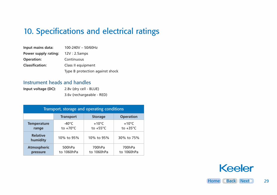
10. Specifications and electrical ratings
Inputmainsdata: 100-240V – 50/60Hz
Powersupplyrating: 12V : 2.5amps
Operation: Continuous
Classification: Class II equipment
Type B protection against shock
Instrument heads and handlesInputvoltage(DC): 2.8v (dry cell - BLUE)
3.6v (rechargeable - RED)
Transport, storage and operating conditions
Transport Storage Operation
Temperaturerange
-40°Cto +70°C
+10°Cto +55°C
+10°Cto +35°C
Relativehumidity
10% to 95% 10% to 95% 30% to 75%
Atmosphericpressure
500hPato 1060hPa
700hPato 1060hPa
700hPato 1060hPa
NextHome Back 30
11. Annex I – EMC statement and guidelines
Keeler Diagnostic Instruments and associated power systems are
medical electrical instruments. These instruments require special care
concerning electromagnetic compatibility (EMC). This section describes
the suitability in terms of electromagnetic compatibility of these
instruments. When installing or using these instruments, please read
carefully and observe what is described here.
Portable or mobile-type radio frequency communication units may
have an adverse effect on these instruments, resulting in
malfunctioning.
Instrument heads and handles are considered to be inherently EMC
benign¹, with the exception of the GenMed Wall Unit, to which the
following table refers, in addition to the Lithium Chargers.
¹ Refer to section 1.1.4 of the Guide for the EMC Directive 2004/108/EC (21st May 2007).
NextHome Back 31
11. Annex I – EMC statement and guidelines
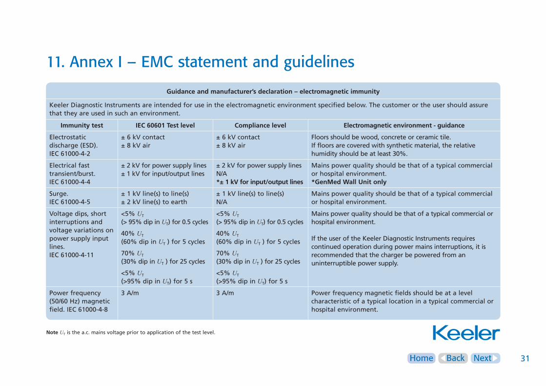
Guidanceandmanufacturer’sdeclaration–electromagneticimmunity
Keeler Diagnostic Instruments are intended for use in the electromagnetic environment specified below. The customer or the user should assure that they are used in such an environment.
Immunitytest IEC60601Testlevel Compliancelevel Electromagneticenvironment-guidance
Electrostaticdischarge (ESD).IEC 61000-4-2
± 6 kV contact± 8 kV air
± 6 kV contact± 8 kV air
Floors should be wood, concrete or ceramic tile.If floors are covered with synthetic material, the relative humidity should be at least 30%.
Electrical fasttransient/burst.IEC 61000-4-4
± 2 kV for power supply lines± 1 kV for input/output lines
± 2 kV for power supply linesN/A*±1kVforinput/outputlines
Mains power quality should be that of a typical commercial or hospital environment.*GenMedWallUnitonly
Surge.IEC 61000-4-5
± 1 kV line(s) to line(s)± 2 kV line(s) to earth
± 1 kV line(s) to line(s)N/A
Mains power quality should be that of a typical commercial or hospital environment.
Voltage dips, shortinterruptions andvoltage variations onpower supply inputlines.IEC 61000-4-11
<5% UT
(> 95% dip in UT) for 0.5 cycles
40% UT
(60% dip in UT ) for 5 cycles
70% UT (30% dip in UT ) for 25 cycles
<5% UT
(>95% dip in UT) for 5 s
<5% UT
(> 95% dip in UT) for 0.5 cycles
40% UT
(60% dip in UT ) for 5 cycles
70% UT (30% dip in UT ) for 25 cycles
<5% UT
(>95% dip in UT) for 5 s
Mains power quality should be that of a typical commercial or hospital environment.
If the user of the Keeler Diagnostic Instruments requires continued operation during power mains interruptions, it is recommended that the charger be powered from an uninterruptible power supply.
Power frequency(50/60 Hz) magneticfield. IEC 61000-4-8
3 A/m 3 A/m Power frequency magnetic fields should be at a level characteristic of a typical location in a typical commercial or hospital environment.
Note UT is the a.c. mains voltage prior to application of the test level.
NextHome Back 32
11. Annex I – EMC statement and guidelines
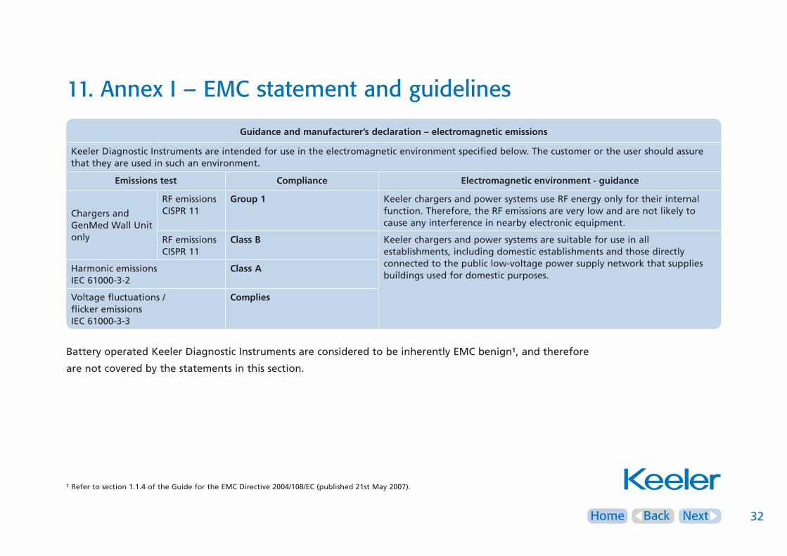
Guidanceandmanufacturer’sdeclaration–electromagneticemissions
Keeler Diagnostic Instruments are intended for use in the electromagnetic environment specified below. The customer or the user should assure that they are used in such an environment.
Emissionstest Compliance Electromagneticenvironment-guidance
Chargers and GenMed Wall Unit only
RF emissions CISPR 11
Group1 Keeler chargers and power systems use RF energy only for their internal function. Therefore, the RF emissions are very low and are not likely to cause any interference in nearby electronic equipment.
RF emissions CISPR 11
ClassB Keeler chargers and power systems are suitable for use in all establishments, including domestic establishments and those directly connected to the public low-voltage power supply network that supplies buildings used for domestic purposes.
Harmonic emissionsIEC 61000-3-2
ClassA
Voltage fluctuations /flicker emissionsIEC 61000-3-3
Complies
Battery operated Keeler Diagnostic Instruments are considered to be inherently EMC benign¹, and therefore
are not covered by the statements in this section.
¹ Refer to section 1.1.4 of the Guide for the EMC Directive 2004/108/EC (published 21st May 2007).
NextHome Back 33
11. Annex I – EMC statement and guidelines
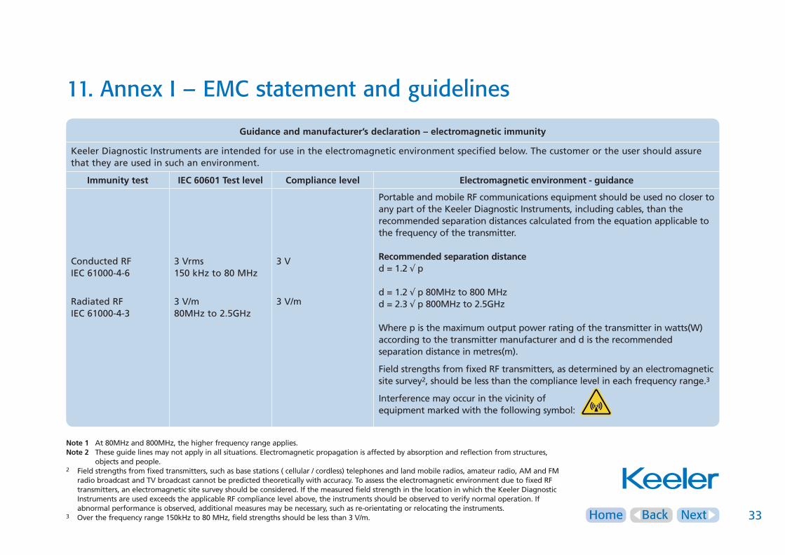
Guidanceandmanufacturer’sdeclaration–electromagneticimmunity
Keeler Diagnostic Instruments are intended for use in the electromagnetic environment specified below. The customer or the user should assure that they are used in such an environment.
Immunitytest IEC60601Testlevel Compliancelevel Electromagneticenvironment-guidance
Conducted RF IEC 61000-4-6
Radiated RFIEC 61000-4-3
3 Vrms150 kHz to 80 MHz
3 V/m80MHz to 2.5GHz
3 V
3 V/m
Portable and mobile RF communications equipment should be used no closer to any part of the Keeler Diagnostic Instruments, including cables, than the recommended separation distances calculated from the equation applicable to the frequency of the transmitter.
Recommendedseparationdistanced = 1.2 √ p
d = 1.2 √ p 80MHz to 800 MHzd = 2.3 √ p 800MHz to 2.5GHz
Where p is the maximum output power rating of the transmitter in watts(W) according to the transmitter manufacturer and d is the recommended separation distance in metres(m).
Field strengths from fixed RF transmitters, as determined by an electromagnetic site survey2, should be less than the compliance level in each frequency range.3
Interference may occur in the vicinity of equipment marked with the following symbol:
Note1 At 80MHz and 800MHz, the higher frequency range applies.Note2 These guide lines may not apply in all situations. Electromagnetic propagation is affected by absorption and reflection from structures, objects and people.2 Field strengths from fixed transmitters, such as base stations ( cellular / cordless) telephones and land mobile radios, amateur radio, AM and FM radio broadcast and TV broadcast cannot be predicted theoretically with accuracy. To assess the electromagnetic environment due to fixed RF transmitters, an electromagnetic site survey should be considered. If the measured field strength in the location in which the Keeler Diagnostic Instruments are used exceeds the applicable RF compliance level above, the instruments should be observed to verify normal operation. If abnormal performance is observed, additional measures may be necessary, such as re-orientating or relocating the instruments.3 Over the frequency range 150kHz to 80 MHz, field strengths should be less than 3 V/m.

NextHome Back 34
11. Annex I – EMC statement and guidelines
RecommendedseparationdistancesbetweenportableandmobileRFcommunicationsequipmentandKeelerDiagnosticInstruments
Keeler Diagnostic Instruments are intended for the use in an electromagnetic environment in which radiated RF disturbances are controlled. The customer or the user of Keeler Diagnostic Instruments can help prevent electromagnetic interference by maintaining a minimum distance between portable and mobile RF communications equipment (transmitters) and the Keeler instruments as recommended below, according to the maximum output power of the communications equipment.
Ratedmaximumoutputpowerof
transmitterW
Separationdistanceaccordingtofrequencyoftransmitterm
150 kHz to 80MHzd = 1.2√ p
80MHz to 800MHzd = 1.2√ p
800MHz to 2.5GHzd = 2.3√ p
0.01 0.12 0.12 0.23
0.1 0.37 0.37 0.74
1 1.2 1.2 2.3
10 3.7 3.7 7.4
100 12 12 23
For transmitters rated at a maximum output power not listed above, the recommended separation distance d in metres (m) can be determined using the equation applicable to the frequency of the transmitter, where p is the maximum output power rating of the transmitter in watts (W) according to the transmitter manufacturer.
Note1 At 80MHz and 800MHz, the higher frequency range applies.Note2 These guide lines may not apply in all situations. Electromagnetic propagation is affected by absorption and reflection from structures, objects and people.

NextHome Back 35
12. Spare parts and accessories
The following replacement bulbs are available for Keeler
diagnostic instruments:
Upgrading your C-size handle from dry cell to rechargeable:
Replace 2.8v bulb with correct 3.6v version as per table above
In addition the following accessories are available from the
distributor:
Part Number Description
1011-P-7050 2x 2.8v Halogen Pocket ophthalmoscope bulbs
1011-P-7106 2x 2.8v Xenon ophthalmoscope bulbs
1011-P-7114 2x 3.6v Xenon ophthalmoscope bulbs
1013-P-7006 2x 2.8v Professional Spot retinoscope bulbs
1013-P-7007 2x 3.6v Professional Spot retinoscope bulbs
1013-P-7008 2x 2.8v Professional Streak retinoscope bulbs
1013-P-7009 2x 3.6v Professional Streak retinoscope bulbs
1305-P-7000 1x Professional Streak retinoscope LED
1015-P-7023 2x 3.6v Halogen Standard/Deluxe otoscope bulbs
1015-P-7031 2x 2.8v Halogen Standard/Deluxe otoscope bulbs
1015-P-7058 2x 3.6v Practitioner/Fibre Optic otoscope bulbs
1015-P-7066 2x 2.8v Practitioner/Fibre Optic otoscope bulbs
Part Number Description
EP29-32777 Power supply
EP39-18918 Slimline 3.6v Lithium battery
1501-P-7117Airtight Chamber with Lens for Pocket and Standard otoscopes
1501-P-7133Pneumatic Testing Adaptor for ‘old type’ Standard and Pocket otoscopes
1513-P-7034 Viewing lens for Practitioner otoscope
1514-P-7028Pneumatic Testing Adaptor for Practitioner, Fibre Optic, Standard and Pocket otoscope
1531-P-5016 3x Magnifier for Deluxe otoscope
1599-P-7237Bulb extractor for Deluxe, Standard and Pocket otoscope
1599-P-7245 Insufflator bulb for all otoscopes
1941-P-1341 Lithium Mini Charger
1941-P-1368 Lithium Double Charger
Part Number Description
1911-P-5229 Battery cap (red)
1919-P-7069 3.6v NiCad battery
1941-P-5246 Double charger
NextHome Back 36
13. Warranty
Warning:Donotmodifythisequipmentwithout
authorizationofKeeler.
No user serviceable parts – all preventative maintenance and
servicing must only be performed by authorised Keeler
representatives.
Your Keeler product is guaranteed for 3 years and will be
replaced, or repaired free of charge subject to the following:-
• Any fault due to faulty manufacture
• The instrument and accessories have been used in compliance
with these instructions
• Proof of purchase accompanies any claim
Please note that bulbs and batteries are not covered by this
warranty statement.

Home Back 37Home Back
14. Contact and disposal information
Keeler LimitedClewer Hill RoadWindsorBerkshire SL4 4AAEngland
Freephone: 0800 521 251Tel: +44 (0)1753 857177Fax: +44 (0)1753 827145
Keeler Instruments Inc.456 ParkwayBroomallPA 19008,USA
Toll Free: 1 800 523 5620Tel: 610 353 4350Fax: 610 353 7814
Disposal of old Electrical and Electronic Equipment (Applicable in the European Union and other European Countries with
separate Collection Systems).
This symbol on the product or on its packaging and instructions
indicates that it was put on the market place after August 2005 and
that this product shall not be treated as Household Waste.
To reduce the environmental impact of WEEE (Waste Electrical Electronic
Equipment) and minimise the volume of WEEE entering landfills we
encourage at product end of life that this equipment is recycled and reused.
Ifyouneedmoreinformationonthecollectionreuseandrecyclingthen
pleasecontactB2BComplianceon01691676124(+441691676124).
EP59-11234 Issue 3