Ophthalmic sensing technologies for ocular disease diagnostics
29
Analyst CRITICAL REVIEW Cite this: Analyst, 2021, 146, 6416 Received 11th July 2021, Accepted 21st September 2021 DOI: 10.1039/d1an01244d rsc.li/analyst Ophthalmic sensing technologies for ocular disease diagnostics Yuqi Shi, a Nan Jiang, * b Priyanka Bikkannavar, c M. Francesca Cordeiro c,d and Ali K. Yetisen * a Point-of-care diagnosis and personalized treatments are critical in ocular physiology and disease. Continuous sampling of tear fluid for ocular diagnosis is a need for further exploration. Several techniques have been developed for possible ophthalmological applications, from traditional spectroscopies to wear- able sensors. Contact lenses are commonly used devices for vision correction, as well as for other thera- peutic and cosmetic purposes. They are increasingly being developed into ocular sensors, being used to sense and monitor biochemical analytes in tear fluid, ocular surface temperature, intraocular pressure, and pH value. These sensors have had success in detecting ocular conditions, optimizing pharmaceutical treatments, and tracking treatment efficacy in point-of-care settings. However, there is a paucity of new and effective instrumentation reported in ophthalmology. Hence, this review will summarize the applied ophthalmic technologies for ocular diagnostics and tear monitoring, including both conventional and biosensing technologies. Besides applications of smart readout devices for continuous monitoring, tar- geted biomarkers are also discussed for the convenience of diagnosis of various ocular diseases. A further discussion is also provided for future aspects and market requirements related to the commercialization of novel types of contact lens sensors. 1. Introduction The human eye is an important organ for the perception, transformation, transmission, and assimilation for visual information. Sight is regarded as the most valued sense, as recently shown in a UK-based study. 1 It simplistically can be thought of comprising three layers and encompasses several biological structures (Fig. 1). Amongst the various complex tissues of the human eye, the retina is a vital component enabling detection of a single photon. 2 However, ocular defects are highly prevalent in the modern world. According to the World Health Organization (WHO), visual impairment affected around 1.3 billion people globally as of 2018, and this number is predicted to increase. Amongst this population, 36 million people are blind, 826 million people have a near visual impairment, 3 189 million people suffer from mild dis- tance visual impairment, and 217 million people experience moderate to severe distance visual impairment. 4 The majority of people with vision impairment are from developing countries and aged 50 years or older. 4 The most common causes of visual impairment are refractive errors, cataracts, glaucoma, age-related macular degeneration, corneal opacifi- cation, diabetic retinopathy, childhood blindness and tra- choma. In some cases, the cause of visual impairment remains undetermined. All of these causes can lead to blind- ness, and possibly be accompanied by other conditions includ- ing intellectual disability, cerebral palsy, hearing impairments, and epilepsy. However, approximately 80% of these visual impairments can be avoided if proper testing and diagnostic processes are carried out. 3,4 Furthermore, the expenditure on ocular care and treatments is also enormous. The total cost of vision impairment globally had reached approximately $3 tril- lion in 2011, comprising both direct and indirect health care costs, with $4030 for each patient with ocular dysfunction. 5 The largest direct medical cost was contributed by the hospi- talization and utilization of medical services for diagnosis and treatment in the initial stages of vision impairment and blind- ness. 6 Vision therapy and ocular diagnosis are well-researched areas globally, including in the United States, Australia, and European countries. Both clinical trials and fundamental lab- based research are vital for ophthalmology. Furthermore, vision defects inevitably affect employment in the modern world. For example, vision testing and regulation are common a Department of Chemical Engineering, Imperial College London, South Kensington, London, SW7 2BU, UK. E-mail: [email protected] b West China School of Basic Medical Sciences and Forensic Medicine, Sichuan University, Chengdu 610041, China. E-mail: [email protected] c UCL Institute of Ophthalmology, London, UK d ICORG, Imperial College London, London, UK 6416 | Analyst, 2021, 146, 6416–6444 This journal is © The Royal Society of Chemistry 2021 Open Access Article. Published on 24 September 2021. Downloaded on 1/17/2022 12:33:59 AM. This article is licensed under a Creative Commons Attribution 3.0 Unported Licence. View Article Online View Journal | View Issue
Transcript of Ophthalmic sensing technologies for ocular disease diagnostics
Analyst
CRITICAL REVIEW
Cite this: Analyst, 2021, 146, 6416
Received 11th July 2021,Accepted 21st September 2021
DOI: 10.1039/d1an01244d
rsc.li/analyst
Ophthalmic sensing technologies for oculardisease diagnostics
Yuqi Shi, a Nan Jiang, *b Priyanka Bikkannavar, c M. Francesca Cordeiro c,d
and Ali K. Yetisen *a
Point-of-care diagnosis and personalized treatments are critical in ocular physiology and disease.
Continuous sampling of tear fluid for ocular diagnosis is a need for further exploration. Several techniques
have been developed for possible ophthalmological applications, from traditional spectroscopies to wear-
able sensors. Contact lenses are commonly used devices for vision correction, as well as for other thera-
peutic and cosmetic purposes. They are increasingly being developed into ocular sensors, being used to
sense and monitor biochemical analytes in tear fluid, ocular surface temperature, intraocular pressure,
and pH value. These sensors have had success in detecting ocular conditions, optimizing pharmaceutical
treatments, and tracking treatment efficacy in point-of-care settings. However, there is a paucity of new
and effective instrumentation reported in ophthalmology. Hence, this review will summarize the applied
ophthalmic technologies for ocular diagnostics and tear monitoring, including both conventional and
biosensing technologies. Besides applications of smart readout devices for continuous monitoring, tar-
geted biomarkers are also discussed for the convenience of diagnosis of various ocular diseases. A further
discussion is also provided for future aspects and market requirements related to the commercialization
of novel types of contact lens sensors.
1. Introduction
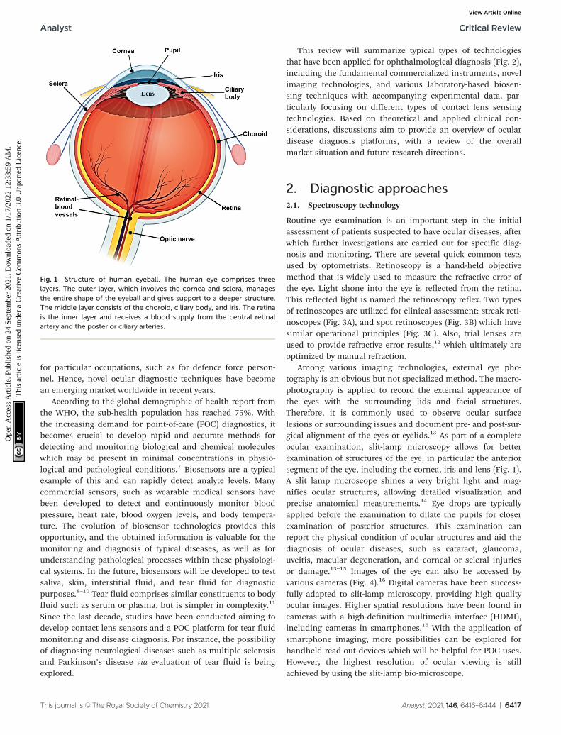
The human eye is an important organ for the perception,transformation, transmission, and assimilation for visualinformation. Sight is regarded as the most valued sense, asrecently shown in a UK-based study.1 It simplistically can bethought of comprising three layers and encompasses severalbiological structures (Fig. 1). Amongst the various complextissues of the human eye, the retina is a vital componentenabling detection of a single photon.2 However, oculardefects are highly prevalent in the modern world. According tothe World Health Organization (WHO), visual impairmentaffected around 1.3 billion people globally as of 2018, and thisnumber is predicted to increase. Amongst this population,36 million people are blind, 826 million people have a nearvisual impairment,3 189 million people suffer from mild dis-tance visual impairment, and 217 million people experiencemoderate to severe distance visual impairment.4 The majority
of people with vision impairment are from developingcountries and aged 50 years or older.4 The most commoncauses of visual impairment are refractive errors, cataracts,glaucoma, age-related macular degeneration, corneal opacifi-cation, diabetic retinopathy, childhood blindness and tra-choma. In some cases, the cause of visual impairmentremains undetermined. All of these causes can lead to blind-ness, and possibly be accompanied by other conditions includ-ing intellectual disability, cerebral palsy, hearing impairments,and epilepsy. However, approximately 80% of these visualimpairments can be avoided if proper testing and diagnosticprocesses are carried out.3,4 Furthermore, the expenditure onocular care and treatments is also enormous. The total cost ofvision impairment globally had reached approximately $3 tril-lion in 2011, comprising both direct and indirect health carecosts, with $4030 for each patient with ocular dysfunction.5
The largest direct medical cost was contributed by the hospi-talization and utilization of medical services for diagnosis andtreatment in the initial stages of vision impairment and blind-ness.6 Vision therapy and ocular diagnosis are well-researchedareas globally, including in the United States, Australia, andEuropean countries. Both clinical trials and fundamental lab-based research are vital for ophthalmology. Furthermore,vision defects inevitably affect employment in the modernworld. For example, vision testing and regulation are common
aDepartment of Chemical Engineering, Imperial College London, South Kensington,
London, SW7 2BU, UK. E-mail: [email protected] China School of Basic Medical Sciences and Forensic Medicine, Sichuan
University, Chengdu 610041, China. E-mail: [email protected] Institute of Ophthalmology, London, UKdICORG, Imperial College London, London, UK
6416 | Analyst, 2021, 146, 6416–6444 This journal is © The Royal Society of Chemistry 2021
Ope
n A
cces
s A
rtic
le. P
ublis
hed
on 2
4 Se
ptem
ber
2021
. Dow
nloa
ded
on 1
/17/
2022
12:
33:5
9 A
M.
Thi
s ar
ticle
is li
cens
ed u
nder
a C
reat
ive
Com
mon
s A
ttrib
utio
n 3.
0 U
npor
ted
Lic
ence
.
View Article OnlineView Journal | View Issue
for particular occupations, such as for defence force person-nel. Hence, novel ocular diagnostic techniques have becomean emerging market worldwide in recent years.
According to the global demographic of health report fromthe WHO, the sub-health population has reached 75%. Withthe increasing demand for point-of-care (POC) diagnostics, itbecomes crucial to develop rapid and accurate methods fordetecting and monitoring biological and chemical moleculeswhich may be present in minimal concentrations in physio-logical and pathological conditions.7 Biosensors are a typicalexample of this and can rapidly detect analyte levels. Manycommercial sensors, such as wearable medical sensors havebeen developed to detect and continuously monitor bloodpressure, heart rate, blood oxygen levels, and body tempera-ture. The evolution of biosensor technologies provides thisopportunity, and the obtained information is valuable for themonitoring and diagnosis of typical diseases, as well as forunderstanding pathological processes within these physiologi-cal systems. In the future, biosensors will be developed to testsaliva, skin, interstitial fluid, and tear fluid for diagnosticpurposes.8–10 Tear fluid comprises similar constituents to bodyfluid such as serum or plasma, but is simpler in complexity.11
Since the last decade, studies have been conducted aiming todevelop contact lens sensors and a POC platform for tear fluidmonitoring and disease diagnosis. For instance, the possibilityof diagnosing neurological diseases such as multiple sclerosisand Parkinson’s disease via evaluation of tear fluid is beingexplored.
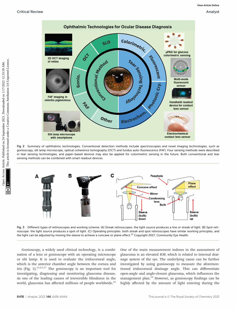
This review will summarize typical types of technologiesthat have been applied for ophthalmological diagnosis (Fig. 2),including the fundamental commercialized instruments, novelimaging technologies, and various laboratory-based biosen-sing techniques with accompanying experimental data, par-ticularly focusing on different types of contact lens sensingtechnologies. Based on theoretical and applied clinical con-siderations, discussions aim to provide an overview of oculardisease diagnosis platforms, with a review of the overallmarket situation and future research directions.
2. Diagnostic approaches2.1. Spectroscopy technology
Routine eye examination is an important step in the initialassessment of patients suspected to have ocular diseases, afterwhich further investigations are carried out for specific diag-nosis and monitoring. There are several quick common testsused by optometrists. Retinoscopy is a hand-held objectivemethod that is widely used to measure the refractive error ofthe eye. Light shone into the eye is reflected from the retina.This reflected light is named the retinoscopy reflex. Two typesof retinoscopes are utilized for clinical assessment: streak reti-noscopes (Fig. 3A), and spot retinoscopes (Fig. 3B) which havesimilar operational principles (Fig. 3C). Also, trial lenses areused to provide refractive error results,12 which ultimately areoptimized by manual refraction.
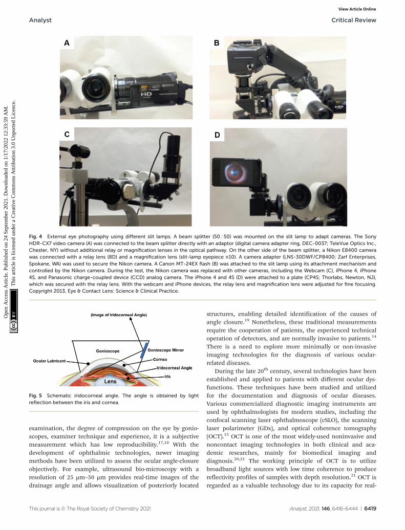
Among various imaging technologies, external eye pho-tography is an obvious but not specialized method. The macro-photography is applied to record the external appearance ofthe eyes with the surrounding lids and facial structures.Therefore, it is commonly used to observe ocular surfacelesions or surrounding issues and document pre- and post-sur-gical alignment of the eyes or eyelids.13 As part of a completeocular examination, slit-lamp microscopy allows for betterexamination of structures of the eye, in particular the anteriorsegment of the eye, including the cornea, iris and lens (Fig. 1).A slit lamp microscope shines a very bright light and mag-nifies ocular structures, allowing detailed visualization andprecise anatomical measurements.14 Eye drops are typicallyapplied before the examination to dilate the pupils for closerexamination of posterior structures. This examination canreport the physical condition of ocular structures and aid thediagnosis of ocular diseases, such as cataract, glaucoma,uveitis, macular degeneration, and corneal or scleral injuriesor damage.13–15 Images of the eye can also be accessed byvarious cameras (Fig. 4).16 Digital cameras have been success-fully adapted to slit-lamp microscopy, providing high qualityocular images. Higher spatial resolutions have been found incameras with a high-definition multimedia interface (HDMI),including cameras in smartphones.16 With the application ofsmartphone imaging, more possibilities can be explored forhandheld read-out devices which will be helpful for POC uses.However, the highest resolution of ocular viewing is stillachieved by using the slit-lamp bio-microscope.
Fig. 1 Structure of human eyeball. The human eye comprises threelayers. The outer layer, which involves the cornea and sclera, managesthe entire shape of the eyeball and gives support to a deeper structure.The middle layer consists of the choroid, ciliary body, and iris. The retinais the inner layer and receives a blood supply from the central retinalartery and the posterior ciliary arteries.
Analyst Critical Review
This journal is © The Royal Society of Chemistry 2021 Analyst, 2021, 146, 6416–6444 | 6417
Ope
n A
cces
s A
rtic
le. P
ublis
hed
on 2
4 Se
ptem
ber
2021
. Dow
nloa
ded
on 1
/17/
2022
12:
33:5
9 A
M.
Thi
s ar
ticle
is li
cens
ed u
nder
a C
reat
ive
Com
mon
s A
ttrib
utio
n 3.
0 U
npor
ted
Lic
ence
.View Article Online
Gonioscopy, a widely used clinical technology, is a combi-nation of a lens or gonioscope with an operating microscopeor slit lamp. It is used to evaluate the iridocorneal angle,which is the anterior chamber angle between the cornea andiris (Fig. 5).13,15,17 The gonioscopy is an important tool forinvestigating, diagnosing and monitoring glaucoma disease.As one of the leading causes of irreversible blindness in theworld, glaucoma has affected millions of people worldwide.15
One of the main measurement indexes in the assessment ofglaucoma is an elevated IOP, which is related to internal drai-nage system of the eye. The underlying cause can be furtherinvestigated by using gonioscopy to measure the aforemen-tioned iridocorneal drainage angle. This can differentiateopen-angle and angle-closure glaucoma, which influences themanagement plan.14 However, as gonioscopy findings can behighly affected by the amount of light entering during the
Fig. 2 Summary of ophthalmic technologies. Conventional detection methods include spectroscopies and novel imaging technologies, such asgonioscopy, slit lamp microscope, optical coherence tomography (OCT) and fundus auto-fluorescence (FAF). Four sensing methods were describedin tear sensing technologies, and paper-based devices may also be applied for colorimetric sensing in the future. Both conventional and tearsensing methods can be combined with smart readout devices.
Fig. 3 Different types of retinoscopes and working scheme. (A) Streak retinoscopes: the light source produces a line or streak of light. (B) Spot reti-noscope: the light source produces a spot of light. (C) Operating principles: both streak and spot retinoscopes have similar working principles, andthe light can be adjusted by moving the sleeve to achieve a concave or plane effect.12 Copyright 2017, Community Eye Health.
Critical Review Analyst
6418 | Analyst, 2021, 146, 6416–6444 This journal is © The Royal Society of Chemistry 2021
Ope
n A
cces
s A
rtic
le. P
ublis
hed
on 2
4 Se
ptem
ber
2021
. Dow
nloa
ded
on 1
/17/
2022
12:
33:5
9 A
M.
Thi
s ar
ticle
is li
cens
ed u
nder
a C
reat
ive
Com
mon
s A
ttrib
utio
n 3.
0 U
npor
ted
Lic
ence
.View Article Online
examination, the degree of compression on the eye by gonio-scopes, examiner technique and experience, it is a subjectivemeasurement which has low reproducibility.17,18 With thedevelopment of ophthalmic technologies, newer imagingmethods have been utilized to assess the ocular angle-closureobjectively. For example, ultrasound bio-microscopy with aresolution of 25 µm–50 µm provides real-time images of thedrainage angle and allows visualization of posteriorly located
structures, enabling detailed identification of the causes ofangle closure.19 Nonetheless, these traditional measurementsrequire the cooperation of patients, the experienced technicaloperation of detectors, and are normally invasive to patients.14
There is a need to explore more minimally or non-invasiveimaging technologies for the diagnosis of various ocular-related diseases.
During the late 20th century, several technologies have beenestablished and applied to patients with different ocular dys-functions. These techniques have been studied and utilizedfor the documentation and diagnosis of ocular diseases.Various commercialized diagnostic imaging instruments areused by ophthalmologists for modern studies, including theconfocal scanning laser ophthalmoscope (cSLO), the scanninglaser polarimeter (GDx), and optical coherence tomography(OCT).15 OCT is one of the most widely-used noninvasive andnoncontact imaging technologies in both clinical and aca-demic researches, mainly for biomedical imaging anddiagnosis.20,21 The working principle of OCT is to utilizebroadband light sources with low time coherence to producereflectivity profiles of samples with depth resolution.21 OCT isregarded as a valuable technology due to its capacity for real-
Fig. 4 External eye photography using different slit lamps. A beam splitter (50 : 50) was mounted on the slit lamp to adapt cameras. The SonyHDR-CX7 video camera (A) was connected to the beam splitter directly with an adaptor (digital camera adapter ring, DEC-0037; TeleVue Optics Inc.,Chester, NY) without additional relay or magnification lenses in the optical pathway. On the other side of the beam splitter, a Nikon E8400 camerawas connected with a relay lens (8D) and a magnification lens (slit-lamp eyepiece ×10). A camera adapter (LNS-30DWF/CP8400; Zarf Enterprises,Spokane, WA) was used to secure the Nikon camera. A Canon MT-24EX flash (B) was attached to the slit lamp using its attachment mechanism andcontrolled by the Nikon camera. During the test, the Nikon camera was replaced with other cameras, including the Webcam (C), iPhone 4, iPhone4S, and Panasonic charge-coupled device (CCD) analog camera. The iPhone 4 and 4S (D) were attached to a plate (CP4S; Thorlabs, Newton, NJ),which was secured with the relay lens. With the webcam and iPhone devices, the relay lens and magnification lens were adjusted for fine focusing.Copyright 2013, Eye & Contact Lens: Science & Clinical Practice.
Fig. 5 Schematic iridocorneal angle. The angle is obtained by lightreflection between the iris and cornea.
Analyst Critical Review
This journal is © The Royal Society of Chemistry 2021 Analyst, 2021, 146, 6416–6444 | 6419
Ope
n A
cces
s A
rtic
le. P
ublis
hed
on 2
4 Se
ptem
ber
2021
. Dow
nloa
ded
on 1
/17/
2022
12:
33:5
9 A
M.
Thi
s ar
ticle
is li
cens
ed u
nder
a C
reat
ive
Com
mon
s A
ttrib
utio
n 3.
0 U
npor
ted
Lic
ence
.View Article Online
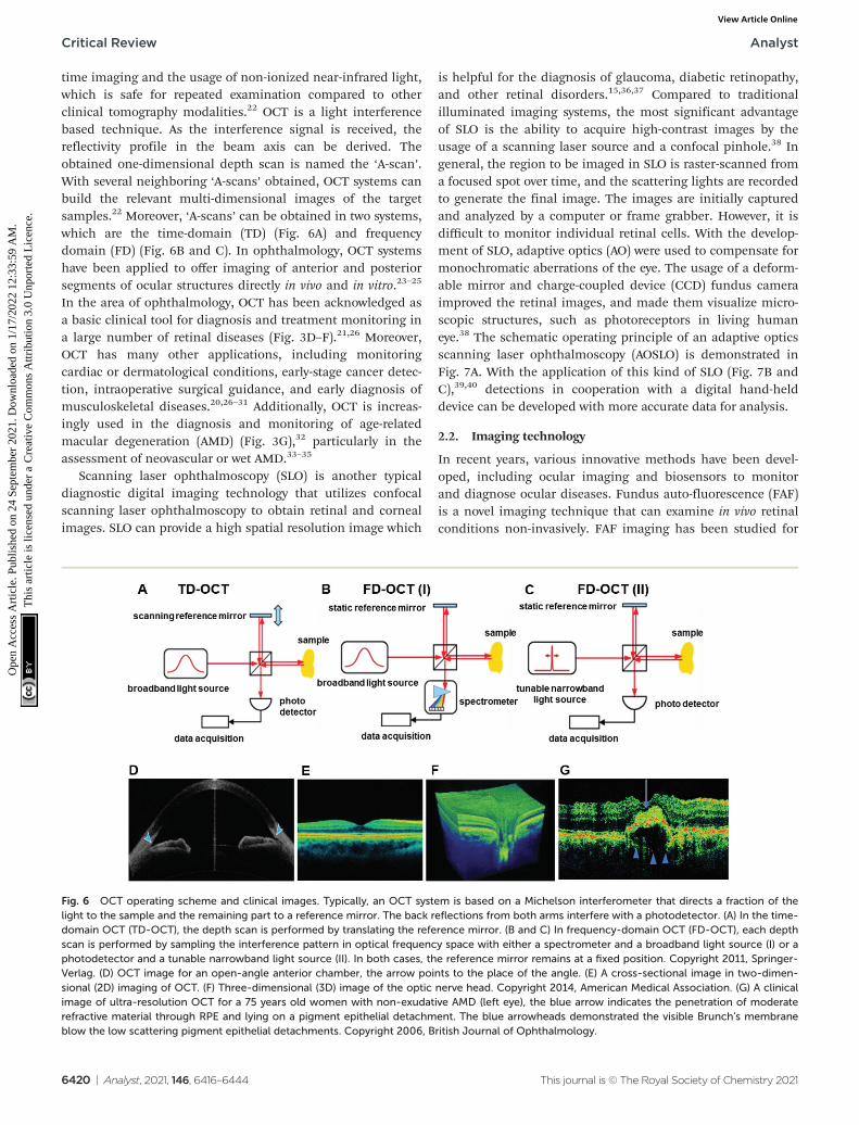
time imaging and the usage of non-ionized near-infrared light,which is safe for repeated examination compared to otherclinical tomography modalities.22 OCT is a light interferencebased technique. As the interference signal is received, thereflectivity profile in the beam axis can be derived. Theobtained one-dimensional depth scan is named the ‘A-scan’.With several neighboring ‘A-scans’ obtained, OCT systems canbuild the relevant multi-dimensional images of the targetsamples.22 Moreover, ‘A-scans’ can be obtained in two systems,which are the time-domain (TD) (Fig. 6A) and frequencydomain (FD) (Fig. 6B and C). In ophthalmology, OCT systemshave been applied to offer imaging of anterior and posteriorsegments of ocular structures directly in vivo and in vitro.23–25
In the area of ophthalmology, OCT has been acknowledged asa basic clinical tool for diagnosis and treatment monitoring ina large number of retinal diseases (Fig. 3D–F).21,26 Moreover,OCT has many other applications, including monitoringcardiac or dermatological conditions, early-stage cancer detec-tion, intraoperative surgical guidance, and early diagnosis ofmusculoskeletal diseases.20,26–31 Additionally, OCT is increas-ingly used in the diagnosis and monitoring of age-relatedmacular degeneration (AMD) (Fig. 3G),32 particularly in theassessment of neovascular or wet AMD.33–35
Scanning laser ophthalmoscopy (SLO) is another typicaldiagnostic digital imaging technology that utilizes confocalscanning laser ophthalmoscopy to obtain retinal and cornealimages. SLO can provide a high spatial resolution image which
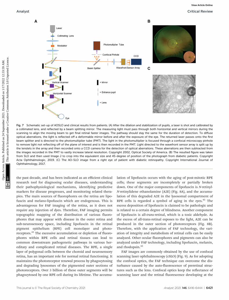
is helpful for the diagnosis of glaucoma, diabetic retinopathy,and other retinal disorders.15,36,37 Compared to traditionalilluminated imaging systems, the most significant advantageof SLO is the ability to acquire high-contrast images by theusage of a scanning laser source and a confocal pinhole.38 Ingeneral, the region to be imaged in SLO is raster-scanned froma focused spot over time, and the scattering lights are recordedto generate the final image. The images are initially capturedand analyzed by a computer or frame grabber. However, it isdifficult to monitor individual retinal cells. With the develop-ment of SLO, adaptive optics (AO) were used to compensate formonochromatic aberrations of the eye. The usage of a deform-able mirror and charge-coupled device (CCD) fundus cameraimproved the retinal images, and made them visualize micro-scopic structures, such as photoreceptors in living humaneye.38 The schematic operating principle of an adaptive opticsscanning laser ophthalmoscopy (AOSLO) is demonstrated inFig. 7A. With the application of this kind of SLO (Fig. 7B andC),39,40 detections in cooperation with a digital hand-helddevice can be developed with more accurate data for analysis.
2.2. Imaging technology
In recent years, various innovative methods have been devel-oped, including ocular imaging and biosensors to monitorand diagnose ocular diseases. Fundus auto-fluorescence (FAF)is a novel imaging technique that can examine in vivo retinalconditions non-invasively. FAF imaging has been studied for
Fig. 6 OCT operating scheme and clinical images. Typically, an OCT system is based on a Michelson interferometer that directs a fraction of thelight to the sample and the remaining part to a reference mirror. The back reflections from both arms interfere with a photodetector. (A) In the time-domain OCT (TD-OCT), the depth scan is performed by translating the reference mirror. (B and C) In frequency-domain OCT (FD-OCT), each depthscan is performed by sampling the interference pattern in optical frequency space with either a spectrometer and a broadband light source (I) or aphotodetector and a tunable narrowband light source (II). In both cases, the reference mirror remains at a fixed position. Copyright 2011, Springer-Verlag. (D) OCT image for an open-angle anterior chamber, the arrow points to the place of the angle. (E) A cross-sectional image in two-dimen-sional (2D) imaging of OCT. (F) Three-dimensional (3D) image of the optic nerve head. Copyright 2014, American Medical Association. (G) A clinicalimage of ultra-resolution OCT for a 75 years old women with non-exudative AMD (left eye), the blue arrow indicates the penetration of moderaterefractive material through RPE and lying on a pigment epithelial detachment. The blue arrowheads demonstrated the visible Brunch’s membraneblow the low scattering pigment epithelial detachments. Copyright 2006, British Journal of Ophthalmology.
Critical Review Analyst
6420 | Analyst, 2021, 146, 6416–6444 This journal is © The Royal Society of Chemistry 2021
Ope
n A
cces
s A
rtic
le. P
ublis
hed
on 2
4 Se
ptem
ber
2021
. Dow
nloa
ded
on 1
/17/
2022
12:
33:5
9 A
M.
Thi
s ar
ticle
is li
cens
ed u
nder
a C
reat
ive
Com
mon
s A
ttrib
utio
n 3.
0 U
npor
ted
Lic
ence
.View Article Online
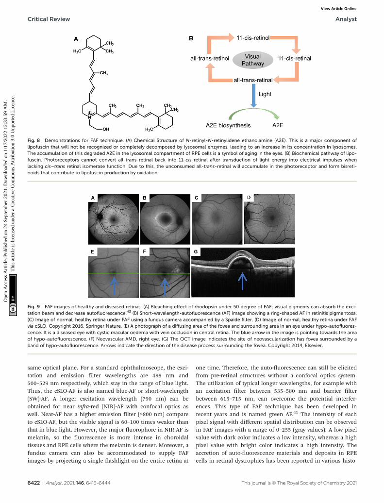
the past decade, and has been indicated as an efficient clinicalresearch tool for diagnosing ocular diseases, understandingtheir pathophysiological mechanisms, identifying predictivemarkers for disease progresses, and monitoring related thera-pies. The main sources of fluorophores on the retina are lipo-fuscin and melano-lipofuscin which are endogenous. This isadvantageous for FAF imaging of the retina, as it does notrequire any injection of dyes. Therefore, FAF imaging permitstopographic mapping of the distribution of various fluoro-phores that may appear with disease in the outer retina andsub-neurosensory space, including lipofuscin in the retinalpigment epithelium (RPE) cell monolayer and photo-receptors.41 The excessive accumulation or depletion of fluoro-phores within RPE cells and retinal tissues can lead tocommon downstream pathogenetic pathways in various her-editary and complicated retinal diseases. The RPE, a singlelayer of polygonal cells between the choroid and neurosensoryretina, has an important role for normal retinal functioning. Itmaintains the photoreceptor renewal process by phagocytosingand degrading lysosomes of the pigmented outer sections ofphotoreceptors. Over 3 billion of these outer segments will bephagocytosed by one RPE cell during its lifetime. The accumu-
lation of lipofuscin occurs with the aging of post-mitotic RPEcells; these segments are incompletely or partially brokendown. One of the major components of lipofuscin is N-retinyl-N-retinylidene ethanolamine (A2E) (Fig. 8A), and the accumu-lation of this degraded A2E in the lysosomal compartment ofRPE cells is regarded a symbol of aging in the eyes.42 Theexcess deposition of lipofuscin is claimed to be pathologic andis related to a certain degree of blindness. Another componentof lipofuscin is all-trans-retinal, which is a toxic aldehyde. Asthe excess of all-trans-retinal exposes to the light, A2E can beproduced in the outer section of photoreceptors (Fig. 8B).Therefore, with the application of FAF technology, the vari-ation of integrity and metabolism of retinal cells can be easilyanalyzed. Other ocular fluorophores and pigments can also beanalyzed under FAF technology, including lipofuscin, melanin,and rhodopsin.42
FAF images are commonly obtained by the use of confocalscanning laser ophthalmoscopy (cSLO) (Fig. 9). As for adoptingthe confocal optics, the FAF technique can overcome the dis-turbance caused by the auto-fluorescence of preretinal struc-tures such as the lens. Confocal optics keep the reflectance ofscanning laser and the retinal fluorescence developing at the
Fig. 7 Schematic set-up of AOSLO and clinical results from patients. (A) After the dilation and stabilization of pupils, a laser is shot and calibrated bya collimated lens, and reflected by a beam splitting mirror. The measuring light must pass through both horizontal and vertical mirrors during thescanning to align the moving beam to get final retinal faster images. The pathway should stay the same for the duration of detection. To diffuseoptical aberrations, the light is reflected off a deformable mirror before and after the exposure of the eye. The returned laser passes onto the firstbeam splitter and is directed to the photomultiplier tube (PMT). The light in the photomultiplier is focused through a confocal microscopy pinholeto remove light not reflecting off of the plane of interest and is then recorded in the PMT. Light directed to the wavefront sensor array is split up bythe lenslets in the array and then recorded onto a CCD camera for the detection of optical aberrations. These aberrations are then subtracted fromthe images recorded in the PMT to vastly increase lateral resolution. Copyright 2002, Optical Society of America. (B) The resulted figure was takenfrom SLO and then used Image J to crop into the equivalent size and 45-degree of position of the photograph from diabetic patients. CopyrightActa Ophthalmologic, 2019. (C) The AO-SLO image from a right eye of patient with diabetic retinopathy. Copyright International Journal ofOphthalmology, 2017.
Analyst Critical Review
This journal is © The Royal Society of Chemistry 2021 Analyst, 2021, 146, 6416–6444 | 6421
Ope
n A
cces
s A
rtic
le. P
ublis
hed
on 2
4 Se
ptem
ber
2021
. Dow
nloa
ded
on 1
/17/
2022
12:
33:5
9 A
M.
Thi
s ar
ticle
is li
cens
ed u
nder
a C
reat
ive
Com
mon
s A
ttrib
utio
n 3.
0 U
npor
ted
Lic
ence
.View Article Online
same optical plane. For a standard ophthalmoscope, the exci-tation and emission filter wavelengths are 488 nm and500–529 nm respectively, which stay in the range of blue light.Thus, the cSLO-AF is also named blue-AF or short-wavelength(SW)-AF. A longer excitation wavelength (790 nm) can beobtained for near infra-red (NIR)-AF with confocal optics aswell. Near-AF has a higher emission filter (>800 nm) compareto cSLO-AF, but the visible signal is 60–100 times weaker thanthat in blue light. However, the major fluorophore in NIR-AF ismelanin, so the fluorescence is more intense in choroidaltissues and RPE cells where the melanin is denser. Moreover, afundus camera can also be accommodated to supply FAFimages by projecting a single flashlight on the entire retina at
one time. Therefore, the auto-fluorescence can still be elicitedfrom pre-retinal structures without a confocal optics system.The utilization of typical longer wavelengths, for example withan excitation filter between 535–580 nm and barrier filterbetween 615–715 nm, can overcome the potential interfer-ences. This type of FAF technique has been developed inrecent years and is named green AF.41 The intensity of eachpixel signal with different spatial distribution can be observedin FAF images with a range of 0–255 (gray values). A low pixelvalue with dark color indicates a low intensity, whereas a highpixel value with bright color indicates a high intensity. Theaccretion of auto-fluorescence materials and deposits in RPEcells in retinal dystrophies has been reported in various histo-
Fig. 8 Demonstrations for FAF technique. (A) Chemical Structure of N-retinyl-N-retinylidene ethanolamine (A2E). This is a major component oflipofuscin that will not be recognized or completely decomposed by lysosomal enzymes, leading to an increase in its concentration in lysosomes.The accumulation of this degraded A2E in the lysosomal compartment of RPE cells is a symbol of aging in the eyes. (B) Biochemical pathway of lipo-fuscin. Photoreceptors cannot convert all-trans-retinal back into 11-cis-retinal after transduction of light energy into electrical impulses whenlacking cis–trans retinal isomerase function. Due to this, the unconsumed all-trans-retinal will accumulate in the photoreceptor and form bisreti-noids that contribute to lipofuscin production by oxidation.
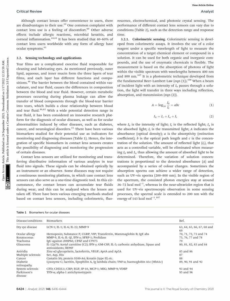
Fig. 9 FAF images of healthy and diseased retinas. (A) Bleaching effect of rhodopsin under 50 degree of FAF; visual pigments can absorb the exci-tation beam and decrease autofluorescence.43 (B) Short-wavelength-autofluorescence (AF) image showing a ring-shaped AF in retinitis pigmentosa.(C) Image of normal, healthy retina under FAF using a fundus camera accompanied by a Spaide filter. (D) Image of normal, healthy retina under FAFvia cSLO. Copyright 2016, Springer Nature. (E) A photograph of a diffusing area of the fovea and surrounding area in an eye under hypo-autofluores-cence. It is a diseased eye with cystic macular oedema with vein occlusion in central retina. The blue arrow in the image is pointing towards the areaof hypo-autofluorescence. (F) Neovascular AMD, right eye. (G) The OCT image indicates the site of neovascularization has fovea surrounded by aband of hypo-autofluorescence. Arrows indicate the direction of the disease process surrounding the fovea. Copyright 2014, Elsevier.
Critical Review Analyst
6422 | Analyst, 2021, 146, 6416–6444 This journal is © The Royal Society of Chemistry 2021
Ope
n A
cces
s A
rtic
le. P
ublis
hed
on 2
4 Se
ptem
ber
2021
. Dow
nloa
ded
on 1
/17/
2022
12:
33:5
9 A
M.
Thi
s ar
ticle
is li
cens
ed u
nder
a C
reat
ive
Com
mon
s A
ttrib
utio
n 3.
0 U
npor
ted
Lic
ence
.View Article Online

pathological studies. Any deviation from a normal recordingwould be recognized when analyzing the FAF image.Therefore, FAF imaging technologies have been applied tostudy a wide range of ocular diseases, including retinitis pig-mentosa, diabetic retinopathy, white dot syndromes, retinalartery occlusion, and age-related macular degeneration (AMD)(Fig. 9). Moreover, the obtained FAF image can be analyzedtogether with the cross-sectional OCT images.
Hence, FAF imaging technology can be significant inproviding informative data for retinal dystrophies, where thehealth of RPE cells is an important measurement index.The variation of lipofuscin in RPE cells can be visualizedthrough images. Furthermore, the imaging technique canalso have potential future applications for identifying the high-risk characteristics or biomarkers of ocular diseases andperforming clinical trial interventions in specific cases.The combination of the fluorescence and spectroscopycould provide creative ideas for ocular smart sensingtechnologies.
3. Contact lens sensors3.1. Advances in contact lens sensors
Contact lenses, as wearable devices for various ocular pur-poses, are used by over 150 million people globally44 and3.7 million people in the United Kingdom.45 The current appli-cations of contact lenses include vision correction, thera-peutics, and cosmetics.46 In recent years, contact lenses areincreasingly being developed as minimally invasive continuoussensing platforms for diagnostics and drug delivery in oph-thalmology.44 The design and materials of a contact lens arebased on their applied purpose. The structure of tear film isaltered after the insertion of contact lens onto the ocular. Theevaporation rate of tear film would increase due to the disrup-tion of lens within tear film and lead to the lipid layer discon-tinuous.47 All contact lenses can alter the tear film as theyinteract with the components within tears and interfere withthe lid-corneal congruity, hence it can be divided into threecategories due to their physiochemical properties and designcharacteristics, including rigid lenses, elastomeric lenses and
hydrogel lenses. Different types of contact lenses react differ-ently with tear film, it can be varied due to the hydration,thickness, speed of dehydration and evaporation rate.47,48
Moreover, contact lenses are also defined by their geometry,and can be classified as scleral, mini-scleral, or corneal(Fig. 10A).
Over the last decade, contact lens sensors have been widelystudied, with the monitoring of ocular disorders, such as dryeye, glaucoma, and diabetic retinopathy, being one of theirprimary applications.44 Various indicators have been studiedvia contact lens sensors including pH, temperature, electro-lytes, and IOP.46,49–52 However, tear fluid analysis has not beencomprehensively studied. Tear film comprises of three layers:the lipid layer, aqueous layer, and mucous layer.53 Researchinvolving proteomic analyses reveals that over 2000 proteinsare found in tears.54 Established functions of the tear filminclude creating a smooth surface, supplying sufficient oxygenand nutrients to the ocular surface, removing irritants, andassisting the immune system on the ocular surface.55 Due tothe less complex nature of tear fluid than serum and plasma,numerous biomarkers in tear fluid may be useful in predictive,preventive, and personalized medicine.54 In addition, contactlenses can also be used to assist typical ocular dysfunctionsand color vision deficiency (CVD). Recently, researchers havedeveloped contact lenses that cross-link with selected dyes ornanoparticles to block out the wavelengths (540–580 nm) thatcreate issues for people with red-green CVD.56,57 Overall,contact lenses involved in continuous tear film sampling, andsome functionalized contact lens sensors have many potentialapplications for disease diagnostics and treatment.
Contact lenses are utilized globally for the correction ofrefractive errors, such as myopia, hyperopia, and astigma-tism.44 Therapeutic contact lenses can be used to maintainand restore the integrity of ocular tissues, such as in cornealabrasion.44,58 Furthermore, cosmetic contact lenses are widelyavailable, for example coloured lenses are extremely popular inAsian countries.44 Contact lenses developed as smart devicesfor continuous monitoring in POC settings have receivedincreasing attention recently, because outcome sensors can bepowered externally and accompanied with wireless smart-phone readouts.44,49–51
Fig. 10 The contact lenses species. (A) The variety of contact lenses is indicated with their diameters. (B) Image of different contact lenses. Scalebar: 4.0 mm Copyright 2017, Elsevier.
Analyst Critical Review
This journal is © The Royal Society of Chemistry 2021 Analyst, 2021, 146, 6416–6444 | 6423
Ope
n A
cces
s A
rtic
le. P
ublis
hed
on 2
4 Se
ptem
ber
2021
. Dow
nloa
ded
on 1
/17/
2022
12:
33:5
9 A
M.
Thi
s ar
ticle
is li
cens
ed u
nder
a C
reat
ive
Com
mon
s A
ttrib
utio
n 3.
0 U
npor
ted
Lic
ence
.View Article Online
Although contact lenses offer convenience to users, thereare disadvantages to their use.59 One common complaint withcontact lens use is a feeling of discomfort.60 Other adverseeffects include allergic reactions, microbial keratitis, andcorneal inflammation.44,61 It has been studied that 40–60% ofcontact lens users worldwide with any form of allergy haveocular symptoms.61
3.2. Sensing technology and applications
Tear films are a complicated exocrine fluid responsible forcleaning and lubricating eyes. As mentioned previously, outerlipid, aqueous, and inner mucin form the three layers of tearfilms, and each layer has different functions and compo-sitions.46 The barrier between the blood contained within vas-culature, and tear fluid, causes the differences in compositionbetween the blood and tear fluid. However, certain metabolicprocesses occurring during plasma leakage can allow thetransfer of blood components through the blood-tear barrierinto tears, which builds a close relationship between bloodand tear fluid.46,62 With a wide potential detection range intear fluid, it has been considered an innovative research plat-form for the diagnosis of ocular diseases, as well as for ocularabnormalities induced by other diseases, such as diabetes,cancer, and neurological disorders.11 There have been variousbiomarkers studied for their potential use as indicators formonitoring and diagnosing diseases (Table 1). Hence, the inte-gration of specific biomarkers in contact lens sensors createsthe possibility of diagnosing and monitoring the progressionof certain diseases.
Contact lens sensors are utilized for monitoring and trans-ferring distributive information of various analytes in tearfluid into signals. These signals can be obtained optically byan instrument or an observer. Some diseases may not requirea continuous monitoring platform, in which case contact lenssensors can also serve as a one-time diagnostic tool. In this cir-cumstance, the contact lenses can accumulate tear fluidsduring wear, and this can be analyzed when the lenses aretaken off. There have been various emerging methods studiedbased on contact lens sensors, including colorimetric, fluo-
rescence, electrochemical, and photonic crystal sensing. Theperformance of different contact lens sensors can vary due toconditions (Table 2), such as the detection range and responsetime.
3.2.1. Colorimetric sensing. Colorimetric sensing is devel-oped from colorimetric assays. It involves the use of a colorreagent under a specific wavelength of light to measure theconcentration of a target chemical element or compound in asolution. It can be used for both organic and inorganic com-pounds, and the use of enzymatic chemicals is flexible. Themeasurement is based on the absorption of photons of lightwithin the visible spectrum with wavelengths between 400 nmand 800 nm.107 It is a photometric technique developed fromthe fundamental Beer–Lambert Law (eqn (1)).108 When a beamof incident light with an intensity of I0 passes through a solu-tion, the light will transfer in three ways including reflection,absorption, and transmission (eqn (2)).
A ¼ log10I0It¼ abc ð1Þ
I0 ¼ Ir þ Ia þ It ð2Þ
where I0 is the intensity of light; Ir is the reflected light; Ia isthe absorbed light; It is the transmitted light; A indicates theabsorbance (optical density); a is the absorptivity (extinctioncoefficient); b is the optical path length and c is the concen-tration of the solution. The amount of reflected light (Ir), thatacts as a controlled variable, will be eliminated when measur-ing I0 and It, thus allowing the amount of absorbed light to bedetermined. Therefore, the variation of solution concen-trations is proportional to the detected absorbance (A) andaccompanied by a series of colour changes. Sometimes theabsorption spectra can achieve a wider range of detection,such as UV–vis spectra (200–800 nm). In the visible region ofthe spectrum, the consisted photon energies stay at around36–72 kcal mol−1, whereas in the near-ultraviolet region that isused for UV–vis spectroscopic observation in some sensingprocesses, the spectral scale is extended to 200 nm with theenergy of 143 kcal mol−1.107
Table 1 Biomarkers for ocular diseases
Disease/conditions Biomarkers Ref.
Dry eye disease LCN-1; IL-1; IL-6; IL-22; MMP-9 63, 64, 65, 66, 67, 68 and69
Ocular allergy Hemopexin; Substance P, CGRP, VIP; Transferrin, Mammaglobin B; IgE abs 70, 71, 72, 73 and 74Keratoconus MMP-9, IL-6; IL-1β, IFN-γ; SFRP-1; Prolidase 75, 76, 77 and 78Trachoma IgG against cHSP60, CPAF and CT975 79Glaucoma IL-12p70; Acetyl carnitine (C2); IFN-γ; GM-CSF; IL-5; carbonic anhydrase, lipase and
antioxidants; BDNF80, 81, 82, 83 and 84
Aniridia Zinc-α2-glycopritein, lactoferrin, VEGF; Ap4A and Ap5A 85 and 86Multiple sclerosis Ser, Asp, His 87Cancer Cystatin SA; protein S100-A4; Keratin (type II) etc. 88Diabeticretinopathy
Lysozyme C; lacritin, lipophilin A, Ig lambda chain; TNF-α; haemoglobin A1c (HbA1c) 89, 90, 91 and 92
System sclerosis CFD; CHI3L1; CRP; EGF; IP-10, MCP-1; MIG; MMP-9; VDBP 93 and 94Parkinson’sdisease
TFN-α; alpha-1 antichymotrypsin 95 and 96
Critical Review Analyst
6424 | Analyst, 2021, 146, 6416–6444 This journal is © The Royal Society of Chemistry 2021
Ope
n A
cces
s A
rtic
le. P
ublis
hed
on 2
4 Se
ptem
ber
2021
. Dow
nloa
ded
on 1
/17/
2022
12:
33:5
9 A
M.
Thi
s ar
ticle
is li
cens
ed u
nder
a C
reat
ive
Com
mon
s A
ttrib
utio
n 3.
0 U
npor
ted
Lic
ence
.View Article Online
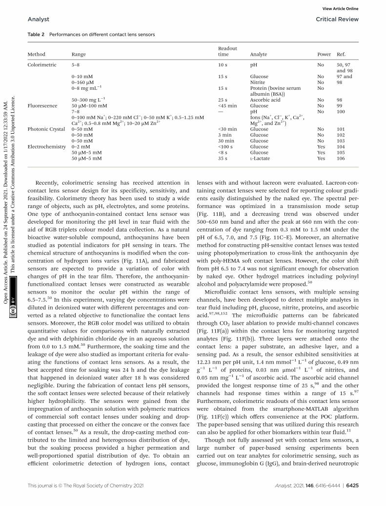
Recently, colorimetric sensing has received attention incontact lens sensor design for its specificity, sensitivity, andfeasibility. Colorimetry theory has been used to study a widerange of objects, such as pH, electrolytes, and some proteins.One type of anthocyanin-contained contact lens sensor wasdeveloped for monitoring the pH level in tear fluid with theaid of RGB triplets colour model data collection. As a naturalbioactive water-soluble compound, anthocyanins have beenstudied as potential indicators for pH sensing in tears. Thechemical structure of anthocyanins is modified when the con-centration of hydrogen ions varies (Fig. 11A), and fabricatedsensors are expected to provide a variation of color withchanges of pH in the tear film. Therefore, the anthocyanin-functionalized contact lenses were constructed as wearablesensors to monitor the ocular pH within the range of6.5–7.5.50 In this experiment, varying dye concentrations werediluted in deionized water with different percentages and con-verted as a related objective to functionalize the contact lenssensors. Moreover, the RGB color model was utilized to obtainquantitative values for comparisons with naturally extracteddye and with delphinidin chloride dye in an aqueous solutionfrom 0.0 to 1.5 mM.50 Furthermore, the soaking time and theleakage of dye were also studied as important criteria for evalu-ating the functions of contact lens sensors. As a result, thebest accepted time for soaking was 24 h and the dye leakagethat happened in deionized water after 18 h was considerednegligible. During the fabrication of contact lens pH sensors,the soft contact lenses were selected because of their relativelyhigher hydrophilicity. The sensors were gained from theimpregnation of anthocyanin solution with polymeric matricesof commercial soft contact lenses under soaking and drop-casting that processed on either the concave or the convex faceof contact lenses.50 As a result, the drop-casting method con-tributed to the limited and heterogenous distribution of dye,but the soaking process provided a higher permeation andwell-proportioned spatial distribution of dye. To obtain anefficient colorimetric detection of hydrogen ions, contact
lenses with and without lacreon were evaluated. Lacreon-con-taining contact lenses were selected for reporting colour gradi-ents easily distinguished by the naked eye. The spectral per-formance was optimized in a transmission mode setup(Fig. 11B), and a decreasing trend was observed under500–650 nm band and after the peak at 660 nm with the con-centration of dye ranging from 0.3 mM to 1.5 mM under thepH of 6.5, 7.0, and 7.5 (Fig. 11C–E). Moreover, an alternativemethod for constructing pH-sensitive contact lenses was testedusing photopolymerization to cross-link the anthocyanin dyewith poly-HEMA soft contact lenses. However, the color shiftfrom pH 6.5 to 7.4 was not significant enough for observationby naked eye. Other hydrogel matrices including polyvinylalcohol and polyacrylamide were proposed.50
Microfluidic contact lens sensors, with multiple sensingchannels, have been developed to detect multiple analytes intear fluid including pH, glucose, nitrite, proteins, and ascorbicacid.97,98,152 The microfluidic patterns can be fabricatedthrough CO2 laser ablation to provide multi-channel concaves(Fig. 11F(a)) within the contact lens for monitoring targetedanalytes (Fig. 11F(b)). Three layers were attached onto thecontact lens: a paper substrate, an adhesive layer, and asensing pad. As a result, the sensor exhibited sensitivities at12.23 nm per pH unit, 1.4 nm mmol−1 L−1 of glucose, 0.49 nmg−1 L−1 of proteins, 0.03 nm μmol−1 L−1 of nitrites, and0.05 nm mg−1 L−1 of ascorbic acid. The ascorbic acid channelprovided the longest response time of 25 s,98 and the otherchannels had response times within a range of 15 s.97
Furthermore, colorimetric readouts of this contact lens sensorwere obtained from the smartphone-MATLAB algorithm(Fig. 11F(c)) which offers convenience at the POC platform.The paper-based sensing that was utilized during this researchcan also be applied for other biomarkers within tear fluid.11
Though not fully assessed yet with contact lens sensors, alarge number of paper-based sensing experiments beencarried out on tear analytes for colorimetric sensing, such asglucose, immunoglobin G (IgG), and brain-derived neurotropic
Table 2 Performances on different contact lens sensors
Method RangeReadouttime Analyte Power Ref.
Colorimetric 5–8 10 s pH No 50, 97and 98
0–10 mM 15 s Glucose No 97 and980–160 µM Nitrite No
0–8 mg mL−1 15 s Protein (bovine serumalbumin (BSA))
No
50–300 mg L−1 25 s Ascorbic acid No 98Fluorescence 50 µM–100 mM <45 min Glucose No 99
7–8 — pH No 1000–100 mM Na+; 0–220 mM Cl−; 0–50 mM K+; 0.5–1.25 mMCa2+; 0.5–0.8 mM Mg2+; 10–20 µM Zn2+
Ions (Na+, Cl−, K+, Ca2+,Mg2+, and Zn2+)
Photonic Crystal 0–50 mM <30 min Glucose No 1010–50 mM 3 min Glucose No 1020–50 mM 30 min Glucose No 103
Electrochemistry 0–2 mM <100 s Glucose Yes 10450 µM–5 mM <8 s Glucose Yes 10550 µM–5 mM 35 s L-Lactate Yes 106
Analyst Critical Review
This journal is © The Royal Society of Chemistry 2021 Analyst, 2021, 146, 6416–6444 | 6425
Ope
n A
cces
s A
rtic
le. P
ublis
hed
on 2
4 Se
ptem
ber
2021
. Dow
nloa
ded
on 1
/17/
2022
12:
33:5
9 A
M.
Thi
s ar
ticle
is li
cens
ed u
nder
a C
reat
ive
Com
mon
s A
ttrib
utio
n 3.
0 U
npor
ted
Lic
ence
.View Article Online

factors (BDNF), to indicate and monitor ocular diseases andother forms of ocular dysfunction. One colorimetric sensingtest of glucose and uric acid (UA) in tears was developed usingchitosan-modified microfluidic paper-based analytical devices(µPAD).109 The best colorimetric sensitivity for glucose and UAwas obtained with a linear response in a concentration range
of 0.1–1.0 mM with the aid of a chromogenic solution, consist-ing of 4-amino anti-pyrine and sodium 3,5-dichloro-2-hydroxy-benzenesulfonate (4-AAP/DHBS). The µPADs were fabricated bya stamping process.110 There are eight detection zones inter-connecting with the central zone by microfluidic channels onthe µPAD (Fig. 12A). During the fabrication process, 3 µL of
Fig. 11 The relative theory and data obtained from the contact lens sensor for pH monitoring. (A) The variation of anthocyanin chemical structurebased on different hydrogen ion concentrations. Under acidic conditions (pH 6.5), the contact lens sensor showed a pink colour, and the colourshifted to blue when the solution changed to alkaline conditions (pH 7.5). (B) The scheme for the setup of spectroscopy measurement in the trans-mission mode. Using a white light source as the incident light which passes through the glass slide and exposes on the fabricated dyed contact lens,the transmitted light is analysed by the spectrometer with a level of 200 lux. (C) Transmittance spectra result under pH 6.5 within a concentration ofanthocyanin range of 0.35–1.50 mM. (D) Transmittance spectra result under pH 7.0 (0.35–1.5 mM of anthocyanin). (E) Under an alkaline (pH 7.5)condition, the resulted transmittance spectra. According to the results of the experiments, the concentration of dye in the solution indicated a func-tion of transmittance. In the range of 500–650 nm, a decreasing trend was observed and showed the peak at 660 nm with the increased concen-tration of dye. Scale bar: 2.0 mm. Copyright 2019, American Chemical Society. (F) Schematics of microfluidic contact lens sensor. (a) A microfluidicsystem was fabricated through CO2 laser ablation which consisted of inlet cave and sensing caves. (b) The final contact lens sensor on an artificialeye model with five different analytes: pH; glucose; nitrite; proteins and ascorbic acid; scale bar: 1.5 cm. (c) A simulation photograph of the workingprocess on the ocular surface for data readout using a mobile phone. Scale bar: 2 cm. Copyright 2020, Lab on a Chip.
Critical Review Analyst
6426 | Analyst, 2021, 146, 6416–6444 This journal is © The Royal Society of Chemistry 2021
Ope
n A
cces
s A
rtic
le. P
ublis
hed
on 2
4 Se
ptem
ber
2021
. Dow
nloa
ded
on 1
/17/
2022
12:
33:5
9 A
M.
Thi
s ar
ticle
is li
cens
ed u
nder
a C
reat
ive
Com
mon
s A
ttrib
utio
n 3.
0 U
npor
ted
Lic
ence
.View Article Online
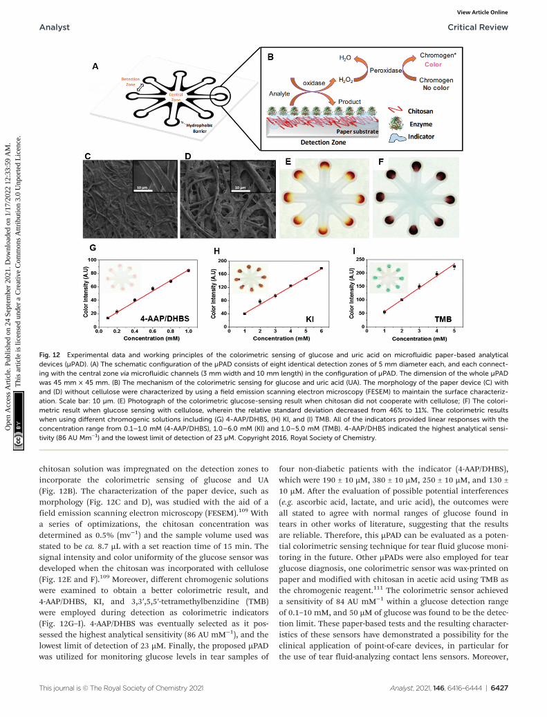
chitosan solution was impregnated on the detection zones toincorporate the colorimetric sensing of glucose and UA(Fig. 12B). The characterization of the paper device, such asmorphology (Fig. 12C and D), was studied with the aid of afield emission scanning electron microscopy (FESEM).109 Witha series of optimizations, the chitosan concentration wasdetermined as 0.5% (mv−1) and the sample volume used wasstated to be ca. 8.7 µL with a set reaction time of 15 min. Thesignal intensity and color uniformity of the glucose sensor wasdeveloped when the chitosan was incorporated with cellulose(Fig. 12E and F).109 Moreover, different chromogenic solutionswere examined to obtain a better colorimetric result, and4-AAP/DHBS, KI, and 3,3′,5,5′-tetramethylbenzidine (TMB)were employed during detection as colorimetric indicators(Fig. 12G–I). 4-AAP/DHBS was eventually selected as it pos-sessed the highest analytical sensitivity (86 AU mM−1), and thelowest limit of detection of 23 µM. Finally, the proposed µPADwas utilized for monitoring glucose levels in tear samples of
four non-diabetic patients with the indicator (4-AAP/DHBS),which were 190 ± 10 µM, 380 ± 10 µM, 250 ± 10 µM, and 130 ±10 µM. After the evaluation of possible potential interferences(e.g. ascorbic acid, lactate, and uric acid), the outcomes wereall stated to agree with normal ranges of glucose found intears in other works of literature, suggesting that the resultsare reliable. Therefore, this µPAD can be evaluated as a poten-tial colorimetric sensing technique for tear fluid glucose moni-toring in the future. Other µPADs were also employed for tearglucose diagnosis, one colorimetric sensor was wax-printed onpaper and modified with chitosan in acetic acid using TMB asthe chromogenic reagent.111 The colorimetric sensor achieveda sensitivity of 84 AU mM−1 within a glucose detection rangeof 0.1–10 mM, and 50 µM of glucose was found to be the detec-tion limit. These paper-based tests and the resulting character-istics of these sensors have demonstrated a possibility for theclinical application of point-of-care devices, in particular forthe use of tear fluid-analyzing contact lens sensors. Moreover,
Fig. 12 Experimental data and working principles of the colorimetric sensing of glucose and uric acid on microfluidic paper-based analyticaldevices (µPAD). (A) The schematic configuration of the µPAD consists of eight identical detection zones of 5 mm diameter each, and each connect-ing with the central zone via microfluidic channels (3 mm width and 10 mm length) in the configuration of µPAD. The dimension of the whole µPADwas 45 mm × 45 mm. (B) The mechanism of the colorimetric sensing for glucose and uric acid (UA). The morphology of the paper device (C) withand (D) without cellulose were characterized by using a field emission scanning electron microscopy (FESEM) to maintain the surface characteriz-ation. Scale bar: 10 µm. (E) Photograph of the colorimetric glucose-sensing result when chitosan did not cooperate with cellulose; (F) The colori-metric result when glucose sensing with cellulose, wherein the relative standard deviation decreased from 46% to 11%. The colorimetric resultswhen using different chromogenic solutions including (G) 4-AAP/DHBS, (H) KI, and (I) TMB. All of the indicators provided linear responses with theconcentration range from 0.1–1.0 mM (4-AAP/DHBS), 1.0–6.0 mM (KI) and 1.0–5.0 mM (TMB). 4-AAP/DHBS indicated the highest analytical sensi-tivity (86 AU Mm−1) and the lowest limit of detection of 23 µM. Copyright 2016, Royal Society of Chemistry.
Analyst Critical Review
This journal is © The Royal Society of Chemistry 2021 Analyst, 2021, 146, 6416–6444 | 6427
Ope
n A
cces
s A
rtic
le. P
ublis
hed
on 2
4 Se
ptem
ber
2021
. Dow
nloa
ded
on 1
/17/
2022
12:
33:5
9 A
M.
Thi
s ar
ticle
is li
cens
ed u
nder
a C
reat
ive
Com
mon
s A
ttrib
utio
n 3.
0 U
npor
ted
Lic
ence
.View Article Online
enzyme-linked immunosorbent assay (ELISA) can also be con-ducted on paper-based platforms to monitor concentrations oftypical biomarkers.112–115 If the paper-based devices can beintegrated into a contact lens sensor, this could be utilized todetect a wide range of biomarkers (Table 1) in tear fluid. Forinstance, detection of BDNF in tears was stated to be capableof diagnosing glaucoma, as glaucoma can be regarded a neuro-degenerative disease.84,116 With the application of a successfulpaper-based ELISA, BDNF can be tested on a µPAD of ELISA,and the assay could be implemented onto a contact lens inorder to monitor tear fluid. However, more potential character-istics of µPADs need to be explored with the aim of fabricatingcontact lens sensors for tear monitoring and diagnostics at thePOC platform.
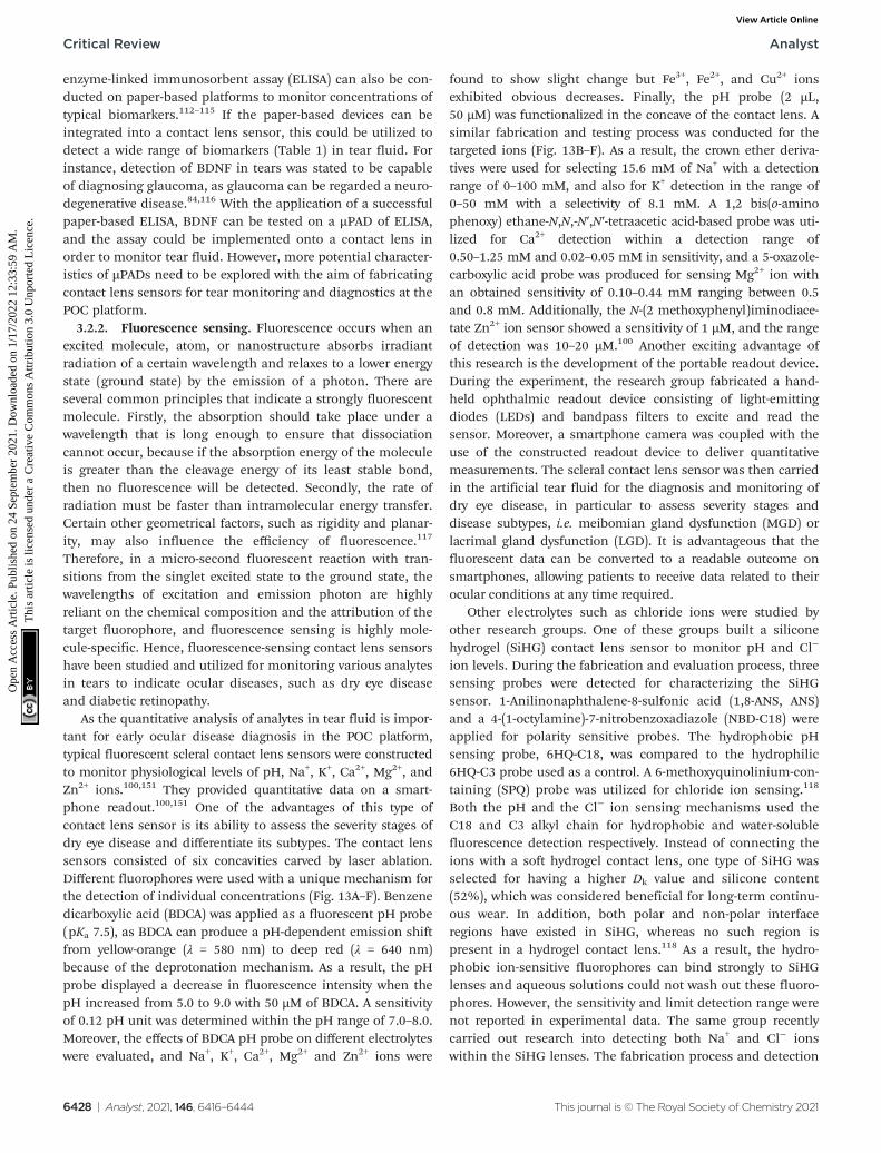
3.2.2. Fluorescence sensing. Fluorescence occurs when anexcited molecule, atom, or nanostructure absorbs irradiantradiation of a certain wavelength and relaxes to a lower energystate (ground state) by the emission of a photon. There areseveral common principles that indicate a strongly fluorescentmolecule. Firstly, the absorption should take place under awavelength that is long enough to ensure that dissociationcannot occur, because if the absorption energy of the moleculeis greater than the cleavage energy of its least stable bond,then no fluorescence will be detected. Secondly, the rate ofradiation must be faster than intramolecular energy transfer.Certain other geometrical factors, such as rigidity and planar-ity, may also influence the efficiency of fluorescence.117
Therefore, in a micro-second fluorescent reaction with tran-sitions from the singlet excited state to the ground state, thewavelengths of excitation and emission photon are highlyreliant on the chemical composition and the attribution of thetarget fluorophore, and fluorescence sensing is highly mole-cule-specific. Hence, fluorescence-sensing contact lens sensorshave been studied and utilized for monitoring various analytesin tears to indicate ocular diseases, such as dry eye diseaseand diabetic retinopathy.
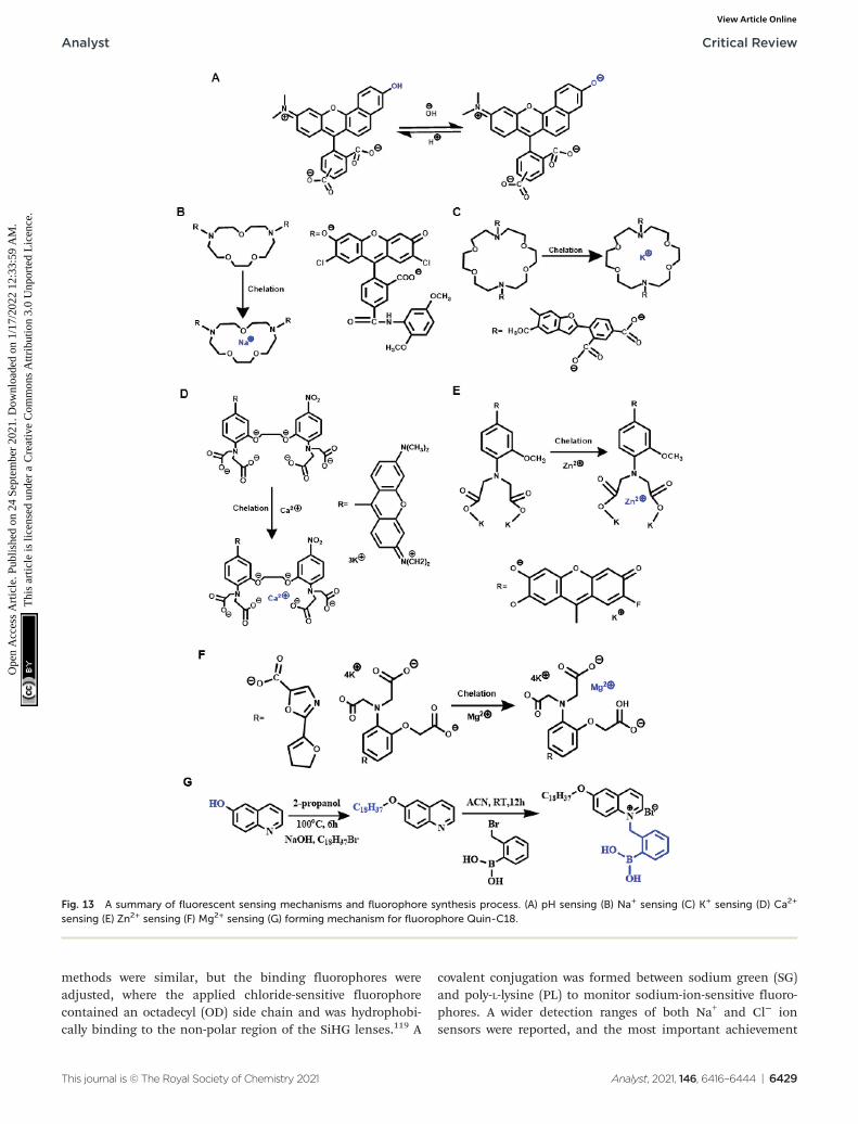
As the quantitative analysis of analytes in tear fluid is impor-tant for early ocular disease diagnosis in the POC platform,typical fluorescent scleral contact lens sensors were constructedto monitor physiological levels of pH, Na+, K+, Ca2+, Mg2+, andZn2+ ions.100,151 They provided quantitative data on a smart-phone readout.100,151 One of the advantages of this type ofcontact lens sensor is its ability to assess the severity stages ofdry eye disease and differentiate its subtypes. The contact lenssensors consisted of six concavities carved by laser ablation.Different fluorophores were used with a unique mechanism forthe detection of individual concentrations (Fig. 13A–F). Benzenedicarboxylic acid (BDCA) was applied as a fluorescent pH probe(pKa 7.5), as BDCA can produce a pH-dependent emission shiftfrom yellow-orange (λ = 580 nm) to deep red (λ = 640 nm)because of the deprotonation mechanism. As a result, the pHprobe displayed a decrease in fluorescence intensity when thepH increased from 5.0 to 9.0 with 50 µM of BDCA. A sensitivityof 0.12 pH unit was determined within the pH range of 7.0–8.0.Moreover, the effects of BDCA pH probe on different electrolyteswere evaluated, and Na+, K+, Ca2+, Mg2+ and Zn2+ ions were
found to show slight change but Fe3+, Fe2+, and Cu2+ ionsexhibited obvious decreases. Finally, the pH probe (2 µL,50 µM) was functionalized in the concave of the contact lens. Asimilar fabrication and testing process was conducted for thetargeted ions (Fig. 13B–F). As a result, the crown ether deriva-tives were used for selecting 15.6 mM of Na+ with a detectionrange of 0–100 mM, and also for K+ detection in the range of0–50 mM with a selectivity of 8.1 mM. A 1,2 bis(o-aminophenoxy) ethane-N,N,-N′,N′-tetraacetic acid-based probe was uti-lized for Ca2+ detection within a detection range of0.50–1.25 mM and 0.02–0.05 mM in sensitivity, and a 5-oxazole-carboxylic acid probe was produced for sensing Mg2+ ion withan obtained sensitivity of 0.10–0.44 mM ranging between 0.5and 0.8 mM. Additionally, the N-(2 methoxyphenyl)iminodiace-tate Zn2+ ion sensor showed a sensitivity of 1 µM, and the rangeof detection was 10–20 µM.100 Another exciting advantage ofthis research is the development of the portable readout device.During the experiment, the research group fabricated a hand-held ophthalmic readout device consisting of light-emittingdiodes (LEDs) and bandpass filters to excite and read thesensor. Moreover, a smartphone camera was coupled with theuse of the constructed readout device to deliver quantitativemeasurements. The scleral contact lens sensor was then carriedin the artificial tear fluid for the diagnosis and monitoring ofdry eye disease, in particular to assess severity stages anddisease subtypes, i.e. meibomian gland dysfunction (MGD) orlacrimal gland dysfunction (LGD). It is advantageous that thefluorescent data can be converted to a readable outcome onsmartphones, allowing patients to receive data related to theirocular conditions at any time required.
Other electrolytes such as chloride ions were studied byother research groups. One of these groups built a siliconehydrogel (SiHG) contact lens sensor to monitor pH and Cl−
ion levels. During the fabrication and evaluation process, threesensing probes were detected for characterizing the SiHGsensor. 1-Anilinonaphthalene-8-sulfonic acid (1,8-ANS, ANS)and a 4-(1-octylamine)-7-nitrobenzoxadiazole (NBD-C18) wereapplied for polarity sensitive probes. The hydrophobic pHsensing probe, 6HQ-C18, was compared to the hydrophilic6HQ-C3 probe used as a control. A 6-methoxyquinolinium-con-taining (SPQ) probe was utilized for chloride ion sensing.118
Both the pH and the Cl− ion sensing mechanisms used theC18 and C3 alkyl chain for hydrophobic and water-solublefluorescence detection respectively. Instead of connecting theions with a soft hydrogel contact lens, one type of SiHG wasselected for having a higher Dk value and silicone content(52%), which was considered beneficial for long-term continu-ous wear. In addition, both polar and non-polar interfaceregions have existed in SiHG, whereas no such region ispresent in a hydrogel contact lens.118 As a result, the hydro-phobic ion-sensitive fluorophores can bind strongly to SiHGlenses and aqueous solutions could not wash out these fluoro-phores. However, the sensitivity and limit detection range werenot reported in experimental data. The same group recentlycarried out research into detecting both Na+ and Cl− ionswithin the SiHG lenses. The fabrication process and detection
Critical Review Analyst
6428 | Analyst, 2021, 146, 6416–6444 This journal is © The Royal Society of Chemistry 2021
Ope
n A
cces
s A
rtic
le. P
ublis
hed
on 2
4 Se
ptem
ber
2021
. Dow
nloa
ded
on 1
/17/
2022
12:
33:5
9 A
M.
Thi
s ar
ticle
is li
cens
ed u
nder
a C
reat
ive
Com
mon
s A
ttrib
utio
n 3.
0 U
npor
ted
Lic
ence
.View Article Online
methods were similar, but the binding fluorophores wereadjusted, where the applied chloride-sensitive fluorophorecontained an octadecyl (OD) side chain and was hydrophobi-cally binding to the non-polar region of the SiHG lenses.119 A
covalent conjugation was formed between sodium green (SG)and poly-L-lysine (PL) to monitor sodium-ion-sensitive fluoro-phores. A wider detection ranges of both Na+ and Cl− ionsensors were reported, and the most important achievement
Fig. 13 A summary of fluorescent sensing mechanisms and fluorophore synthesis process. (A) pH sensing (B) Na+ sensing (C) K+ sensing (D) Ca2+
sensing (E) Zn2+ sensing (F) Mg2+ sensing (G) forming mechanism for fluorophore Quin-C18.
Analyst Critical Review
This journal is © The Royal Society of Chemistry 2021 Analyst, 2021, 146, 6416–6444 | 6429
Ope
n A
cces
s A
rtic
le. P
ublis
hed
on 2
4 Se
ptem
ber
2021
. Dow
nloa
ded
on 1
/17/
2022
12:
33:5
9 A
M.
Thi
s ar
ticle
is li
cens
ed u
nder
a C
reat
ive
Com
mon
s A
ttrib
utio
n 3.
0 U
npor
ted
Lic
ence
.View Article Online
was the independent response from Na+ and Cl− ion detectionon a single lens. These series of research provided a compre-hensive idea about the interfacial region of silicone hydrogelcontact lenses, which could be applied to monitor other ana-lytes within tear fluid for ocular disease diagnosis.
Other fluorescent contact lens sensors have been proposed,including glucose sensing in tear fluid. For instance, aglucose-sensitive silicone hydrogel contact lens was recentlyestablished for continuous tear fluid glucose-monitoringglucose in the near term. Compared to the electrochemical-based sensor module,104 this research simplified the monitor-ing mechanism and used the glucose-sensitive fluorophore(Glu-SFs), Quin-C18, inserted into SiHG lenses.120 During thefabrication process, the interpenetrating polymer network(IPN) that existed in SiHG lenses was evaluated with almostpure silicone and water regions using a polarity-sensitiveprobe, Prodan. The glucose-sensitive fluorophore Quin-C18(Fig. 13G) was then synthesized and consisted of a hydro-phobic chain to localize the probe at the interfacial region.120
This glucose contact lens sensor can be applied for themeasurement of varying glucose concentrations in an in vitroplatform. Significantly, the utilized fluorophore (Quin-C18)bound strongly to lenses with a negligible leaching rate evenafter several rinses. Furthermore, the measurements of glucosesensing were similar even after lenses underwent threemonths of storage in water. Therefore, this is likely to havebeneficial applications for tear glucose-sensing in POC settingsin the near future. Therefore, fluorescence sensing via contactlens sensors, and the ability to obtain the data via handheldreaders, provides the potential to explore the physiological pro-perties of human eyes and further understand the pathophy-siology of ocular diseases, as well having substantial potentialclinical applications.
Instead of applying the fluorescent sensing technologiesono contact lenses, microfluidic paper-based device is also oneof the typical applications that have been studied for tear diag-nosis. Lactoferrin detection without antibody is one of themost significant study for fluorescent µPADs. The microfluidicpatterns on µPADs were fabricated with the inkjet printer anda UV-curable ink.121 The fabricated paper-based sensor canprovide a limit of detection of lactoferrin at 0.3 mg mL−1
within a detection range from 0.5 to 3 mg mL−1. Then, a dis-tance-based lactoferrin was also developed form a similarmethod. An even lower limit of detection of lactoferrin wasachieved at 0.1 mg mL−1 using this kind of paper-basedsensing technology, and the detection range was 0–4 mg mL−1
of lactoferrin.122 With the achievement of detection for tearsusing µPADs, the further development could be then exploredfor implementation of paper-based sensors onto contactlenses to achieve the real-time point-of-care diagnostic plat-form for ocular diseases.
3.2.3. Electrochemical sensing. Microsystem-based contactlens sensing techniques have been well-established in thesemiconductor industry recently. Due to their advantages,including reduced waste production, miniaturized analytesrequirements, fast response times, and low-cost manufacture,
electrochemical sensing techniques are increasingly popularfor use in tear monitoring in POC platforms. Electrochemicalsensors use electrodes as the transducer elements, and canalso be applied in combination with other techniques such asnanotechnology, to increase precision, selectivity, specificity,and sensitivity. These sensors can also be employed for quanti-fying glucose concentrations in tear fluid with the aid of 3-elec-trode systems. Glucose oxidase (GOD) a common enzyme usedfor glucose electrochemical sensing, and the electrical chargecan be created as the enzyme–substrate complex forms. Threemain reactions are included in glucose electrochemicalsensing (eqn (3)–(5)), and the magnitude created by the chargeis proportional to the concentration of oxidized glucose.
D‐glucoseþ O2 �!GOD H2O2 þ D‐gluconolactone ð3Þ
d-gluconolactoneþH2O ! d-gluconic acid ð4Þ
H2O2 ! 2Hþ þ O2 þ 2e� ð5ÞAn electrochemical contact lens sensor monitoring the con-
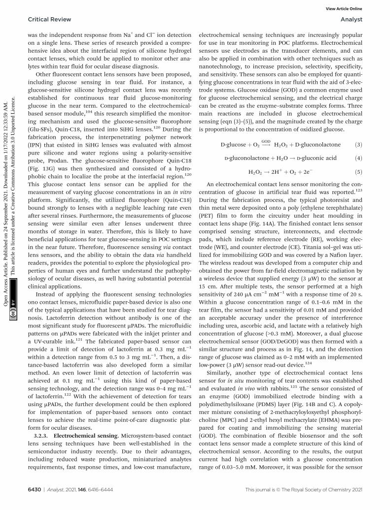
centration of glucose in artificial tear fluid was reported.123
During the fabrication process, the typical photoresist andthin metal were deposited onto a poly (ethylene terephthalate)(PET) film to form the circuitry under heat moulding incontact lens shape (Fig. 14A). The finished contact lens sensorcomprised sensing structure, interconnects, and electrodepads, which include reference electrode (RE), working elec-trode (WE), and counter electrode (CE). Titania sol–gel was uti-lized for immobilizing GOD and was covered by a Nafion layer.The wireless readout was developed from a computer chip andobtained the power from far-field electromagnetic radiation bya wireless device that supplied energy (3 µW) to the sensor at15 cm. After multiple tests, the sensor performed at a highsensitivity of 240 µA cm−2 mM−1 with a response time of 20 s.Within a glucose concentration range of 0.1–0.6 mM in thetear film, the sensor had a sensitivity of 0.01 mM and providedan acceptable accuracy under the presence of interferenceincluding urea, ascorbic acid, and lactate with a relatively highconcentration of glucose (>0.3 mM). Moreover, a dual glucoseelectrochemical sensor (GOD/DeGOD) was then formed with asimilar structure and process as in Fig. 14, and the detectionrange of glucose was claimed as 0–2 mM with an implementedlow-power (3 µW) sensor read-out device.124
Similarly, another type of electrochemical contact lenssensor for in situ monitoring of tear contents was establishedand evaluated in vivo with rabbits.125 The sensor consisted ofan enzyme (GOD) immobilized electrode binding with apolydimethylsiloxane (PDMS) layer (Fig. 14B and C). A copoly-mer mixture consisting of 2-methacryloyloxyethyl phosphoryl-choline (MPC) and 2-ethyl hexyl methacrylate (EHMA) was pre-pared for coating and immobilizing the sensing material(GOD). The combination of flexible biosensor and the softcontact lens sensor made a complete structure of this kind ofelectrochemical sensor. According to the results, the outputcurrent had high correlation with a glucose concentrationrange of 0.03–5.0 mM. Moreover, it was possible for the sensor
Critical Review Analyst
6430 | Analyst, 2021, 146, 6416–6444 This journal is © The Royal Society of Chemistry 2021
Ope
n A
cces
s A
rtic
le. P
ublis
hed
on 2
4 Se
ptem
ber
2021
. Dow
nloa
ded
on 1
/17/
2022
12:
33:5
9 A
M.
Thi
s ar
ticle
is li
cens
ed u
nder
a C
reat
ive
Com
mon
s A
ttrib
utio
n 3.
0 U
npor
ted
Lic
ence
.View Article Online
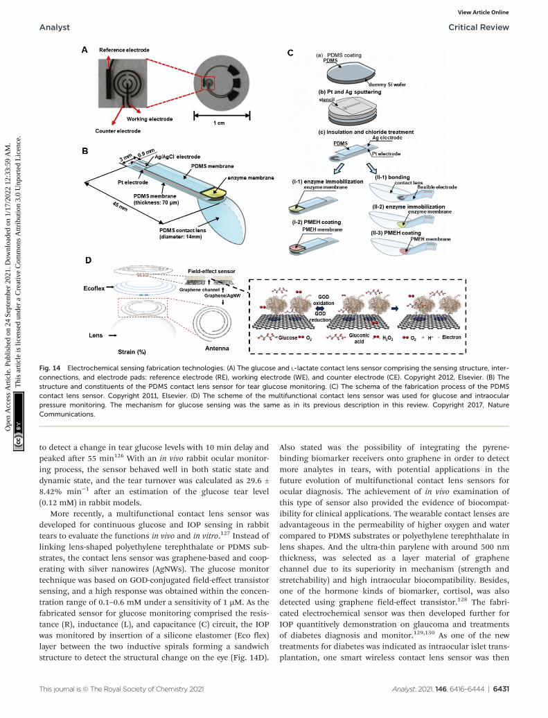
to detect a change in tear glucose levels with 10 min delay andpeaked after 55 min126 With an in vivo rabbit ocular monitor-ing process, the sensor behaved well in both static state anddynamic state, and the tear turnover was calculated as 29.6 ±8.42% min−1 after an estimation of the glucose tear level(0.12 mM) in rabbit models.
More recently, a multifunctional contact lens sensor wasdeveloped for continuous glucose and IOP sensing in rabbittears to evaluate the functions in vivo and in vitro.127 Instead oflinking lens-shaped polyethylene terephthalate or PDMS sub-strates, the contact lens sensor was graphene-based and coop-erating with silver nanowires (AgNWs). The glucose monitortechnique was based on GOD-conjugated field-effect transistorsensing, and a high response was obtained within the concen-tration range of 0.1–0.6 mM under a sensitivity of 1 µM. As thefabricated sensor for glucose monitoring comprised the resis-tance (R), inductance (L), and capacitance (C) circuit, the IOPwas monitored by insertion of a silicone elastomer (Eco flex)layer between the two inductive spirals forming a sandwichstructure to detect the structural change on the eye (Fig. 14D).
Also stated was the possibility of integrating the pyrene-binding biomarker receivers onto graphene in order to detectmore analytes in tears, with potential applications in thefuture evolution of multifunctional contact lens sensors forocular diagnosis. The achievement of in vivo examination ofthis type of sensor also provided the evidence of biocompat-ibility for clinical applications. The wearable contact lenses areadvantageous in the permeability of higher oxygen and watercompared to PDMS substrates or polyethylene terephthalate inlens shapes. And the ultra-thin parylene with around 500 nmthickness, was selected as a layer material of graphenechannel due to its superiority in mechanism (strength andstretchability) and high intraocular biocompatibility. Besides,one of the hormone kinds of biomarker, cortisol, was alsodetected using graphene field-effect transistor.128 The fabri-cated electrochemical sensor was then developed further forIOP quantitively demonstration on glaucoma and treatmentsof diabetes diagnosis and monitor.129,130 As one of the newtreatments for diabetes was indicated as intraocular islet trans-plantation, one smart wireless contact lens sensor was then
Fig. 14 Electrochemical sensing fabrication technologies. (A) The glucose and L-lactate contact lens sensor comprising the sensing structure, inter-connections, and electrode pads: reference electrode (RE), working electrode (WE), and counter electrode (CE). Copyright 2012, Elsevier. (B) Thestructure and constituents of the PDMS contact lens sensor for tear glucose monitoring. (C) The schema of the fabrication process of the PDMScontact lens sensor. Copyright 2011, Elsevier. (D) The scheme of the multifunctional contact lens sensor was used for glucose and intraocularpressure monitoring. The mechanism for glucose sensing was the same as in its previous description in this review. Copyright 2017, NatureCommunications.
Analyst Critical Review
This journal is © The Royal Society of Chemistry 2021 Analyst, 2021, 146, 6416–6444 | 6431
Ope
n A
cces
s A
rtic
le. P
ublis
hed
on 2
4 Se
ptem
ber
2021
. Dow
nloa
ded
on 1
/17/
2022
12:
33:5
9 A
M.
Thi
s ar
ticle
is li
cens
ed u
nder
a C
reat
ive
Com
mon
s A
ttrib
utio
n 3.
0 U
npor
ted
Lic
ence
.View Article Online
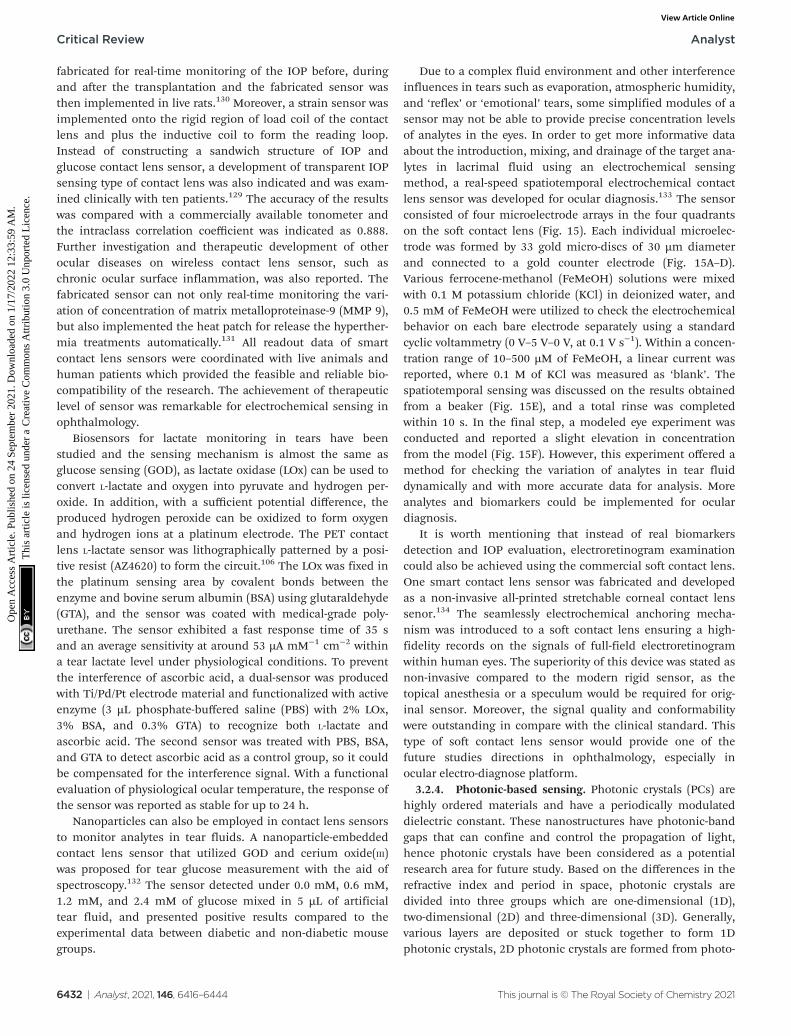
fabricated for real-time monitoring of the IOP before, duringand after the transplantation and the fabricated sensor wasthen implemented in live rats.130 Moreover, a strain sensor wasimplemented onto the rigid region of load coil of the contactlens and plus the inductive coil to form the reading loop.Instead of constructing a sandwich structure of IOP andglucose contact lens sensor, a development of transparent IOPsensing type of contact lens was also indicated and was exam-ined clinically with ten patients.129 The accuracy of the resultswas compared with a commercially available tonometer andthe intraclass correlation coefficient was indicated as 0.888.Further investigation and therapeutic development of otherocular diseases on wireless contact lens sensor, such aschronic ocular surface inflammation, was also reported. Thefabricated sensor can not only real-time monitoring the vari-ation of concentration of matrix metalloproteinase-9 (MMP 9),but also implemented the heat patch for release the hyperther-mia treatments automatically.131 All readout data of smartcontact lens sensors were coordinated with live animals andhuman patients which provided the feasible and reliable bio-compatibility of the research. The achievement of therapeuticlevel of sensor was remarkable for electrochemical sensing inophthalmology.
Biosensors for lactate monitoring in tears have beenstudied and the sensing mechanism is almost the same asglucose sensing (GOD), as lactate oxidase (LOx) can be used toconvert L-lactate and oxygen into pyruvate and hydrogen per-oxide. In addition, with a sufficient potential difference, theproduced hydrogen peroxide can be oxidized to form oxygenand hydrogen ions at a platinum electrode. The PET contactlens L-lactate sensor was lithographically patterned by a posi-tive resist (AZ4620) to form the circuit.106 The LOx was fixed inthe platinum sensing area by covalent bonds between theenzyme and bovine serum albumin (BSA) using glutaraldehyde(GTA), and the sensor was coated with medical-grade poly-urethane. The sensor exhibited a fast response time of 35 sand an average sensitivity at around 53 µA mM−1 cm−2 withina tear lactate level under physiological conditions. To preventthe interference of ascorbic acid, a dual-sensor was producedwith Ti/Pd/Pt electrode material and functionalized with activeenzyme (3 µL phosphate-buffered saline (PBS) with 2% LOx,3% BSA, and 0.3% GTA) to recognize both L-lactate andascorbic acid. The second sensor was treated with PBS, BSA,and GTA to detect ascorbic acid as a control group, so it couldbe compensated for the interference signal. With a functionalevaluation of physiological ocular temperature, the response ofthe sensor was reported as stable for up to 24 h.
Nanoparticles can also be employed in contact lens sensorsto monitor analytes in tear fluids. A nanoparticle-embeddedcontact lens sensor that utilized GOD and cerium oxide(III)was proposed for tear glucose measurement with the aid ofspectroscopy.132 The sensor detected under 0.0 mM, 0.6 mM,1.2 mM, and 2.4 mM of glucose mixed in 5 µL of artificialtear fluid, and presented positive results compared to theexperimental data between diabetic and non-diabetic mousegroups.
Due to a complex fluid environment and other interferenceinfluences in tears such as evaporation, atmospheric humidity,and ‘reflex’ or ‘emotional’ tears, some simplified modules of asensor may not be able to provide precise concentration levelsof analytes in the eyes. In order to get more informative dataabout the introduction, mixing, and drainage of the target ana-lytes in lacrimal fluid using an electrochemical sensingmethod, a real-speed spatiotemporal electrochemical contactlens sensor was developed for ocular diagnosis.133 The sensorconsisted of four microelectrode arrays in the four quadrantson the soft contact lens (Fig. 15). Each individual microelec-trode was formed by 33 gold micro-discs of 30 µm diameterand connected to a gold counter electrode (Fig. 15A–D).Various ferrocene-methanol (FeMeOH) solutions were mixedwith 0.1 M potassium chloride (KCl) in deionized water, and0.5 mM of FeMeOH were utilized to check the electrochemicalbehavior on each bare electrode separately using a standardcyclic voltammetry (0 V–5 V–0 V, at 0.1 V s−1). Within a concen-tration range of 10–500 µM of FeMeOH, a linear current wasreported, where 0.1 M of KCl was measured as ‘blank’. Thespatiotemporal sensing was discussed on the results obtainedfrom a beaker (Fig. 15E), and a total rinse was completedwithin 10 s. In the final step, a modeled eye experiment wasconducted and reported a slight elevation in concentrationfrom the model (Fig. 15F). However, this experiment offered amethod for checking the variation of analytes in tear fluiddynamically and with more accurate data for analysis. Moreanalytes and biomarkers could be implemented for oculardiagnosis.
It is worth mentioning that instead of real biomarkersdetection and IOP evaluation, electroretinogram examinationcould also be achieved using the commercial soft contact lens.One smart contact lens sensor was fabricated and developedas a non-invasive all-printed stretchable corneal contact lenssenor.134 The seamlessly electrochemical anchoring mecha-nism was introduced to a soft contact lens ensuring a high-fidelity records on the signals of full-field electroretinogramwithin human eyes. The superiority of this device was stated asnon-invasive compared to the modern rigid sensor, as thetopical anesthesia or a speculum would be required for orig-inal sensor. Moreover, the signal quality and conformabilitywere outstanding in compare with the clinical standard. Thistype of soft contact lens sensor would provide one of thefuture studies directions in ophthalmology, especially inocular electro-diagnose platform.
3.2.4. Photonic-based sensing. Photonic crystals (PCs) arehighly ordered materials and have a periodically modulateddielectric constant. These nanostructures have photonic-bandgaps that can confine and control the propagation of light,hence photonic crystals have been considered as a potentialresearch area for future study. Based on the differences in therefractive index and period in space, photonic crystals aredivided into three groups which are one-dimensional (1D),two-dimensional (2D) and three-dimensional (3D). Generally,various layers are deposited or stuck together to form 1Dphotonic crystals, 2D photonic crystals are formed from photo-
Critical Review Analyst
6432 | Analyst, 2021, 146, 6416–6444 This journal is © The Royal Society of Chemistry 2021
Ope
n A
cces
s A
rtic
le. P
ublis
hed
on 2
4 Se
ptem
ber
2021
. Dow
nloa
ded
on 1
/17/
2022
12:
33:5
9 A
M.
Thi
s ar
ticle
is li
cens
ed u
nder
a C
reat
ive
Com
mon
s A
ttrib
utio
n 3.
0 U
npor
ted
Lic
ence
.View Article Online
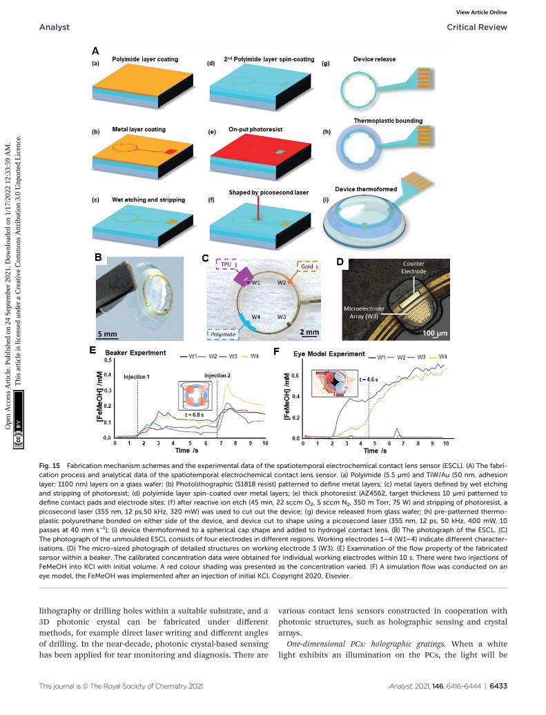
lithography or drilling holes within a suitable substrate, and a3D photonic crystal can be fabricated under differentmethods, for example direct laser writing and different anglesof drilling. In the near-decade, photonic crystal-based sensinghas been applied for tear monitoring and diagnosis. There are
various contact lens sensors constructed in cooperation withphotonic structures, such as holographic sensing and crystalarrays.
One-dimensional PCs: holographic gratings. When a whitelight exhibits an illumination on the PCs, the light will be
Fig. 15 Fabrication mechanism schemes and the experimental data of the spatiotemporal electrochemical contact lens sensor (ESCL). (A) The fabri-cation process and analytical data of the spatiotemporal electrochemical contact lens sensor. (a) Polyimide (5.5 µm) and TiW/Au (50 nm, adhesionlayer; 1100 nm) layers on a glass wafer; (b) Photolithographic (S1818 resist) patterned to define metal layers; (c) metal layers defined by wet etchingand stripping of photoresist; (d) polyimide layer spin-coated over metal layers; (e) thick photoresist (AZ4562, target thickness 10 µm) patterned todefine contact pads and electrode sites; (f ) after reactive ion etch (45 min, 22 sccm O2, 5 sccm N2, 350 m Torr, 75 W) and stripping of photoresist, apicosecond laser (355 nm, 12 ps,50 kHz, 320 mW) was used to cut out the device; (g) device released from glass wafer; (h) pre-patterned thermo-plastic polyurethane bonded on either side of the device, and device cut to shape using a picosecond laser (355 nm, 12 ps, 50 kHz, 400 mW, 10passes at 40 mm s−1); (i) device thermoformed to a spherical cap shape and added to hydrogel contact lens. (B) The photograph of the ESCL. (C)The photograph of the unmoulded ESCL consists of four electrodes in different regions. Working electrodes 1–4 (W1–4) indicate different character-isations. (D) The micro-sized photograph of detailed structures on working electrode 3 (W3). (E) Examination of the flow property of the fabricatedsensor within a beaker. The calibrated concentration data were obtained for individual working electrodes within 10 s. There were two injections ofFeMeOH into KCl with initial volume. A red colour shading was presented as the concentration varied. (F) A simulation flow was conducted on aneye model, the FeMeOH was implemented after an injection of initial KCl. Copyright 2020, Elsevier.
Analyst Critical Review
This journal is © The Royal Society of Chemistry 2021 Analyst, 2021, 146, 6416–6444 | 6433
Ope
n A
cces
s A
rtic
le. P
ublis
hed
on 2
4 Se
ptem
ber
2021
. Dow
nloa
ded
on 1
/17/
2022
12:
33:5
9 A
M.
Thi
s ar
ticle
is li
cens
ed u
nder
a C
reat
ive
Com
mon
s A
ttrib
utio
n 3.
0 U
npor
ted
Lic
ence
.View Article Online
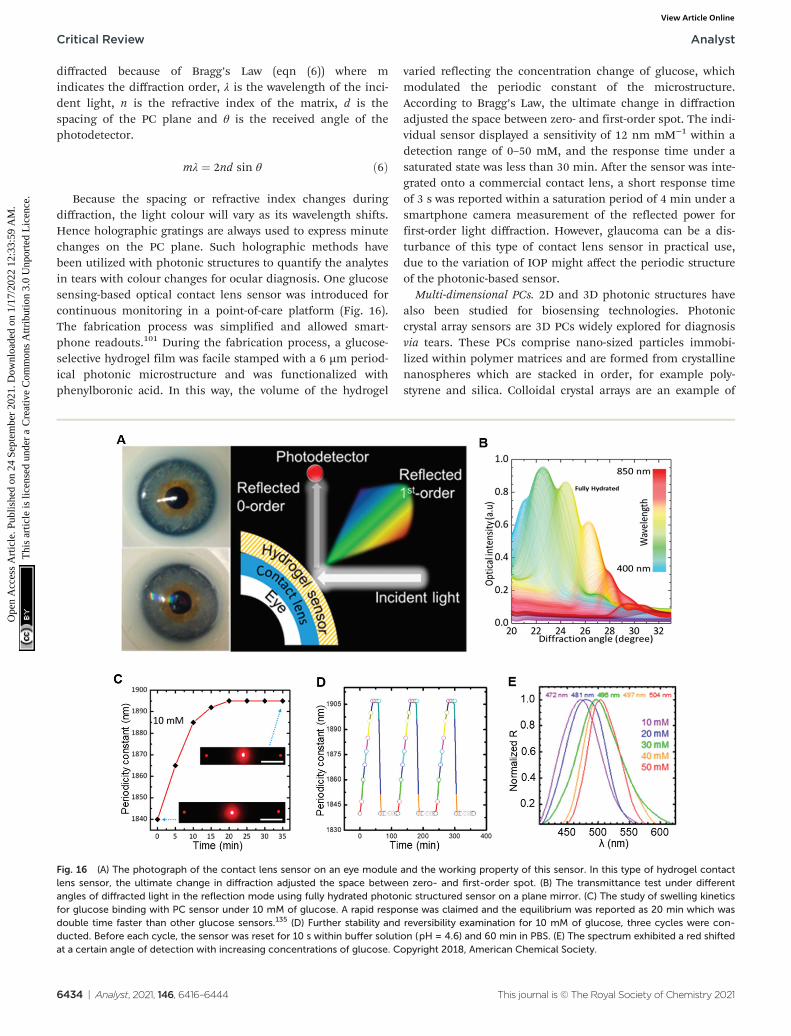
diffracted because of Bragg’s Law (eqn (6)) where mindicates the diffraction order, λ is the wavelength of the inci-dent light, n is the refractive index of the matrix, d is thespacing of the PC plane and θ is the received angle of thephotodetector.
mλ ¼ 2nd sin θ ð6Þ
Because the spacing or refractive index changes duringdiffraction, the light colour will vary as its wavelength shifts.Hence holographic gratings are always used to express minutechanges on the PC plane. Such holographic methods havebeen utilized with photonic structures to quantify the analytesin tears with colour changes for ocular diagnosis. One glucosesensing-based optical contact lens sensor was introduced forcontinuous monitoring in a point-of-care platform (Fig. 16).The fabrication process was simplified and allowed smart-phone readouts.101 During the fabrication process, a glucose-selective hydrogel film was facile stamped with a 6 µm period-ical photonic microstructure and was functionalized withphenylboronic acid. In this way, the volume of the hydrogel
varied reflecting the concentration change of glucose, whichmodulated the periodic constant of the microstructure.According to Bragg’s Law, the ultimate change in diffractionadjusted the space between zero- and first-order spot. The indi-vidual sensor displayed a sensitivity of 12 nm mM−1 within adetection range of 0–50 mM, and the response time under asaturated state was less than 30 min. After the sensor was inte-grated onto a commercial contact lens, a short response timeof 3 s was reported within a saturation period of 4 min under asmartphone camera measurement of the reflected power forfirst-order light diffraction. However, glaucoma can be a dis-turbance of this type of contact lens sensor in practical use,due to the variation of IOP might affect the periodic structureof the photonic-based sensor.
Multi-dimensional PCs. 2D and 3D photonic structures havealso been studied for biosensing technologies. Photoniccrystal array sensors are 3D PCs widely explored for diagnosisvia tears. These PCs comprise nano-sized particles immobi-lized within polymer matrices and are formed from crystallinenanospheres which are stacked in order, for example poly-styrene and silica. Colloidal crystal arrays are an example of
Fig. 16 (A) The photograph of the contact lens sensor on an eye module and the working property of this sensor. In this type of hydrogel contactlens sensor, the ultimate change in diffraction adjusted the space between zero- and first-order spot. (B) The transmittance test under differentangles of diffracted light in the reflection mode using fully hydrated photonic structured sensor on a plane mirror. (C) The study of swelling kineticsfor glucose binding with PC sensor under 10 mM of glucose. A rapid response was claimed and the equilibrium was reported as 20 min which wasdouble time faster than other glucose sensors.135 (D) Further stability and reversibility examination for 10 mM of glucose, three cycles were con-ducted. Before each cycle, the sensor was reset for 10 s within buffer solution (pH = 4.6) and 60 min in PBS. (E) The spectrum exhibited a red shiftedat a certain angle of detection with increasing concentrations of glucose. Copyright 2018, American Chemical Society.
Critical Review Analyst
6434 | Analyst, 2021, 146, 6416–6444 This journal is © The Royal Society of Chemistry 2021
Ope
n A
cces
s A
rtic
le. P
ublis
hed
on 2
4 Se
ptem
ber
2021
. Dow
nloa
ded
on 1
/17/
2022
12:
33:5
9 A
M.
Thi
s ar
ticle
is li
cens
ed u
nder
a C
reat
ive
Com
mon
s A
ttrib
utio
n 3.
0 U
npor
ted
Lic
ence
.View Article Online
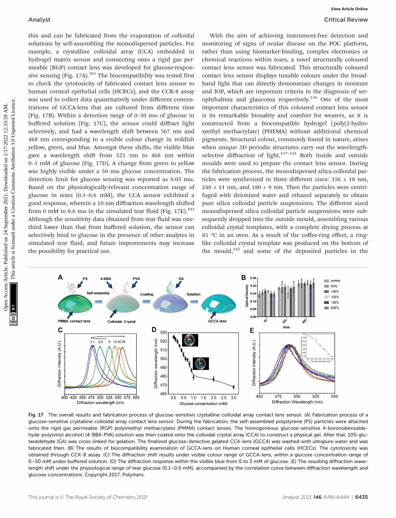
this and can be fabricated from the evaporation of colloidalsolutions by self-assembling the monodispersed particles. Forexample, a crystalline colloidal array (CCA) embedded inhydrogel matrix sensor and connecting onto a rigid gas per-meable (RGP) contact lens was developed for glucose-respon-sive sensing (Fig. 17A).103 The biocompatibility was tested firstto check the cytotoxicity of fabricated contact lens sensor tohuman corneal epithelial cells (HCECs), and the CCK-8 assaywas used to collect data quantitatively under different concen-trations of GCCA-lens that are cultured from different time(Fig. 17B). Within a detection range of 0–50 mM of glucose inbuffered solution (Fig. 17C), the sensor could diffract lightselectively, and had a wavelength shift between 567 nm and468 nm corresponding to a visible colour change in reddishyellow, green, and blue. Amongst these shifts, the visible bluegave a wavelength shift from 525 nm to 468 nm within0–3 mM of glucose (Fig. 17D). A change from green to yellowwas highly visible under a 50 mM glucose concentration. Thedetection limit for glucose sensing was reported as 0.05 mM.Based on the physiologically-relevant concentration range ofglucose in tears (0.1–0.6 mM), the CCA sensor exhibited agood response, wherein a 10 nm diffraction wavelength shiftedfrom 0 mM to 0.6 mM in the simulated tear fluid (Fig. 17E).103
Although the sensitivity data obtained from tear fluid was one-third lower than that from buffered solution, the sensor canselectively bind to glucose in the presence of other analytes insimulated tear fluid, and future improvements may increasethe possibility for practical use.
With the aim of achieving instrument-free detection andmonitoring of signs of ocular disease on the POC platform,rather than using biomarker-binding, complex electronics orchemical reactions within tears, a novel structurally colouredcontact lens sensor was fabricated. This structurally colouredcontact lens sensor displays tunable colours under the broad-band light that can directly demonstrate changes in moistureand IOP, which are important criteria in the diagnosis of xer-ophthalmia and glaucoma respectively.136 One of the mostimportant characteristics of this coloured contact lens sensoris its remarkable biosafety and comfort for wearers, as it isconstructed from a biocompatible hydrogel (poly(2-hydro-xyethyl methacrylate) (PHEMA) without additional chemicalpigments. Structural colour, commonly found in nature, ariseswhen unique 3D periodic structures carry out the wavelength-selective diffraction of light.137–141 Both inside and outsidemoulds were used to prepare the contact lens sensor. Duringthe fabrication process, the monodispersed silica colloidal par-ticles were synthesized in three different sizes: 356 ± 18 nm,240 ± 11 nm, and 180 ± 9 nm. Then the particles were centri-fuged with deionized water and ethanol separately to obtainpure silica colloidal particle suspensions. The different sizedmonodispersed silica colloidal particle suspensions were sub-sequently dropped into the outside mould, assembling variouscolloidal crystal templates, with a complete drying process at85 °C in an oven. As a result of the coffee-ring effect, a ring-like colloidal crystal template was produced on the bottom ofthe mould,142 and some of the deposited particles in the
Fig. 17 The overall results and fabrication process of glucose-sensitive crystalline colloidal array contact lens sensor. (A) Fabrication process of aglucose-sensitive crystalline colloidal array contact lens sensor. During the fabrication, the self-assembled polystyrene (PS) particles were attachedonto the rigid gas permeable (RGP) poly(methyl methacrylate) (PMMA) contact lenses. The homogeneous glucose-sensitive 4-boronobenzalde-hyde-poly(vinyl alcohol) (4-BBA-PVA) solution was then coated onto the colloidal crystal array (CCA) to construct a physical gel. After that, 10% glu-taraldehyde (GA) was cross-linked for gelation. The finalized glucose-detective gelated CCA-lens (GCCA) was washed with ultrapure water and wasfabricated then. (B) The results of biocompatibility examination of GCCA-lens on Human corneal epithelial cells (HCECs). The cytotoxicity wasobtained through CCK-8 assay. (C) The diffraction shift results under visible colour range of GCCA-lens, within a glucose concentration range of0–50 mM under buffered solution. (D) The diffraction response within the visible blue from 0 to 3 mM of glucose. (E) The resulting diffraction wave-length shift under the physiological range of tear glucose (0.1–0.6 mM), accompanied by the correlation curve between diffraction wavelength andglucose concentrations. Copyright 2017, Polymers.
Analyst Critical Review
This journal is © The Royal Society of Chemistry 2021 Analyst, 2021, 146, 6416–6444 | 6435
Ope
n A
cces
s A
rtic
le. P
ublis
hed
on 2
4 Se
ptem
ber
2021
. Dow
nloa
ded
on 1
/17/
2022
12:
33:5
9 A
M.
Thi
s ar
ticle
is li
cens
ed u
nder
a C
reat
ive
Com
mon
s A
ttrib
utio
n 3.
0 U
npor
ted
Lic
ence
.View Article Online
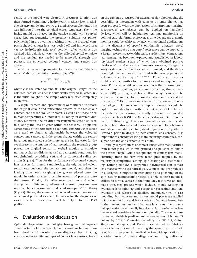
centre of the mould were cleared. A precursor solution wasthen formed containing 2-hydroxyethyl methacrylate, methyl-ene-bis-acrylamide and 1% v/v 2,2-diethoxyacetophenone. Thiswas infiltrated into the colloidal crystal templates. Then, theinside mould was placed on the outside mould with a curvedspace left. Subsequently, the precursor solution was photo-polymerized in a UV curing machine. Then the hydrogel com-posite-shaped contact lens was peeled off and immersed in a4% v/v hydrofluoric acid (HF) solution, after which it waswashed with deionized water, as the colloidal crystal templateand the residual HF needed to be removed. Through thisprocess, the structured coloured contact lens sensor wascreated.
An equation was implemented for the evaluation of the lenssensors’ ability to monitor moisture, (eqn (7)):
P ¼ ðW �WdÞW
� 100% ð7Þ
where P is the water content, W is the original weight of thecoloured contact lens sensor sufficiently swelled in water, Wd
is the initial weight of the sample when W is dried completelyin an oven.
A digital camera and spectrometer were utilized to recordthe original colour and reflectance spectra of the red-colourcontact lens sensor swelled in water, as well as of those driedin room temperature air under 89% humidity for different dur-ations. Moreover, the air-dried measurements were also usedto quantify the loss of water within the sensors. The plottedwavelengths of the reflectance peak with different water losseswere used to obtain a relationship between the colouredcontact lens sensors and the colour change within the sensorin various moistures. Furthermore, as the key indicator for dryeye disease is the amount of tear secretion, the research groupplaced the original sensor in eyeball moulds to simulatenormal ocular conditions, as well as pathogenic conditions forxerophthalmia by adding 5 µL and 15 µL normal saline per5 min (Fig. 18).136 As for the performance of coloured contactlens sensors for pressure monitoring, the original red coloursensor was put onto the contact lens mould, and then theloading units, each weighing 5.0 g, were placed onto themould in order to exert a certain amount of pressure ontothe sensor. Finally, the reflectance spectrum and colourchange with different gradients of exerted pressure wererecorded by a spectrometer and a microscope (Ni-U, Nikon)(Fig. 18). Hence, the constructed coloured contact lens sensoroffers great potential as a simple process for the diagnosis ofvarious ocular diseases, and will be helpful for the POCplatform.
4. Evaluation and discussion
Ophthalmology-related technologies have gained widespreadattention in the last decade. Numerous novel techniques havebeen developed for ocular disease diagnosis, from imagingspectroscopies to different types of contact lens sensors. Based
on the cameras discussed for external ocular photography, thepossibility of integration with cameras on smartphones hasbeen proposed. With the application of smartphone imaging,spectroscopy technologies can be applied on handhelddevices, which will be helpful for real-time monitoring onpoint-of-care platforms. Moreover, a time-dependent dynamicmonitor could be achieved by SLO, with potential applicationsin the diagnosis of specific ophthalmic diseases. Novelimaging techniques using auto-fluorescence can be applied toa larger research space within tears. Furthermore, contact lenstear sensing has been well explored and established in labora-tory-based studies, some of which have obtained positiveresults in vitro and in vivo environments. However, the types ofanalytes detected within tears are still limited, and the detec-tion of glucose and ions in tear fluid is the most popular andwell-established technique.98,101,126,132 Proteins and enzymescould be studied further for tear analysis and subsequent diag-nosis. Furthermore, different means of tear fluid sensing, suchas microfluidic systems, paper-based detection, three-dimen-sional (3D) printing, and lateral flow assays, can also bestudied and combined for improved analysis and personalizedtreatments.143 Hence as an intermediate direction within oph-thalmologic field, some more complex biomarkers could beexplored and developed with different means of detectionmethods for tear sensing, especially for some neuro-relateddiseases such as BDNF for Alzheimer’s disease. On the otherhand, multi-sensing of various biomarkers for one specificocular-related disease could also be explored for obtainingaccurate and reliable data for patient at point-of-care platform.However, prior to designing new contact lens sensors, it isimportant to consider existing manufacturing techniques, con-sumer demand and economic feasibility.
Initially, large volumes of contact lenses were manufacturedfrom blown glass, which was grinded and polished to obtainthe desired shape. With developments in contact lens manu-facturing, there are now three techniques adopted by themajority of companies: lathing, spin coating and cast mould-ing. Lathing employs a dehydrated polymerized soft contactlens material with a cylindrical disk. Contact lens are producedin a designed configuration after cutting and polishing. In thespin casting manufacture process, a single concave mould isutilized to form a surface of the front lens. It involves an auto-matic three-step process which includes mould wetting forhydration; lens spinning and curing for packaging; and lenshydration and release for finalized manufacturing. In castmoulding, both concave and convex mould pieces are appliedto fabricate the front and back surfaces of contact lenses. Dueto the tremendous number of contact lens users, their poten-tial application in minimally invasive ocular prosthetic deviceshas received considerable attention globally. The contact lensmarket worldwide is predicted to increase to over 19 billion USdollars by 2024.44 Countries including the UK, US, China,Singapore, Malaysia and Korea, have started to fabricatecontact lenses not only for existing therapeutic and cosmeticuses, but also as potential medical devices with applications ina wider range of disease diagnoses and drug deliveries.
Critical Review Analyst
6436 | Analyst, 2021, 146, 6416–6444 This journal is © The Royal Society of Chemistry 2021
Ope
n A
cces
s A
rtic
le. P
ublis
hed
on 2
4 Se
ptem
ber
2021
. Dow
nloa
ded
on 1
/17/
2022
12:
33:5
9 A
M.
Thi
s ar
ticle
is li
cens
ed u
nder
a C
reat
ive
Com
mon
s A
ttrib
utio
n 3.
0 U
npor
ted
Lic
ence
.View Article Online
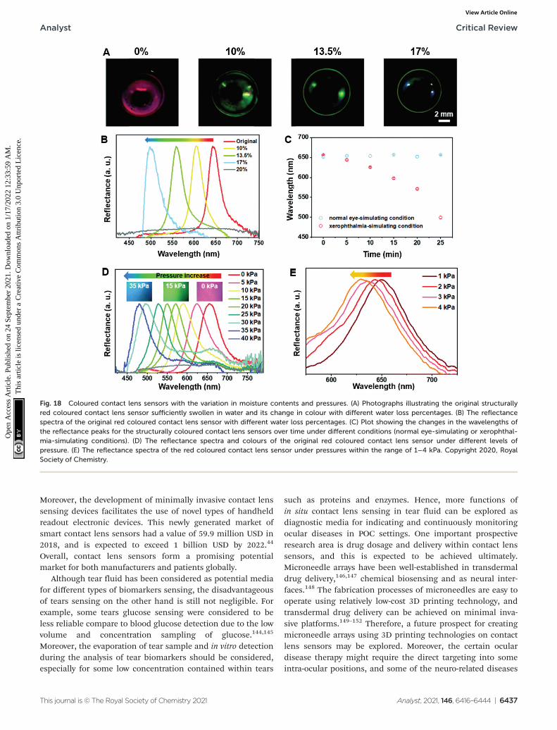
Moreover, the development of minimally invasive contact lenssensing devices facilitates the use of novel types of handheldreadout electronic devices. This newly generated market ofsmart contact lens sensors had a value of 59.9 million USD in2018, and is expected to exceed 1 billion USD by 2022.44
Overall, contact lens sensors form a promising potentialmarket for both manufacturers and patients globally.
Although tear fluid has been considered as potential mediafor different types of biomarkers sensing, the disadvantageousof tears sensing on the other hand is still not negligible. Forexample, some tears glucose sensing were considered to beless reliable compare to blood glucose detection due to the lowvolume and concentration sampling of glucose.144,145
Moreover, the evaporation of tear sample and in vitro detectionduring the analysis of tear biomarkers should be considered,especially for some low concentration contained within tears
such as proteins and enzymes. Hence, more functions ofin situ contact lens sensing in tear fluid can be explored asdiagnostic media for indicating and continuously monitoringocular diseases in POC settings. One important prospectiveresearch area is drug dosage and delivery within contact lenssensors, and this is expected to be achieved ultimately.Microneedle arrays have been well-established in transdermaldrug delivery,146,147 chemical biosensing and as neural inter-faces.148 The fabrication processes of microneedles are easy tooperate using relatively low-cost 3D printing technology, andtransdermal drug delivery can be achieved on minimal inva-sive platforms.149–152 Therefore, a future prospect for creatingmicroneedle arrays using 3D printing technologies on contactlens sensors may be explored. Moreover, the certain oculardisease therapy might require the direct targeting into someintra-ocular positions, and some of the neuro-related diseases
Fig. 18 Coloured contact lens sensors with the variation in moisture contents and pressures. (A) Photographs illustrating the original structurallyred coloured contact lens sensor sufficiently swollen in water and its change in colour with different water loss percentages. (B) The reflectancespectra of the original red coloured contact lens sensor with different water loss percentages. (C) Plot showing the changes in the wavelengths ofthe reflectance peaks for the structurally coloured contact lens sensors over time under different conditions (normal eye-simulating or xerophthal-mia-simulating conditions). (D) The reflectance spectra and colours of the original red coloured contact lens sensor under different levels ofpressure. (E) The reflectance spectra of the red coloured contact lens sensor under pressures within the range of 1–4 kPa. Copyright 2020, RoyalSociety of Chemistry.
Analyst Critical Review
This journal is © The Royal Society of Chemistry 2021 Analyst, 2021, 146, 6416–6444 | 6437
Ope
n A
cces
s A
rtic
le. P
ublis
hed
on 2
4 Se
ptem
ber
2021
. Dow
nloa
ded
on 1
/17/
2022
12:
33:5
9 A
M.
Thi
s ar
ticle
is li
cens
ed u
nder
a C
reat
ive
Com
mon
s A
ttrib
utio
n 3.
0 U
npor
ted
Lic
ence
.View Article Online
such as glaucoma would require the treatment from aqueoushumor as it was stated. By achieving this, the smart contactlens can be applied not only in the tear fluid sensing stage,but also for intra-ocular treatments for ocular related diseaseson POC platforms.
5. Conclusion
Ocular disease diagnosis is an emerging research topic world-wide. Existing developed diagnostic spectroscopies includeretinoscopy, external eye photography, gonioscopy and somenovel imaging technologies, such as cSLO and OCT. Withthese applications, multi-dimensional images can be achievedto monitor physiological or pathological conditions in preciseparts of the eye, which can provide ophthalmologists andresearchers with more informative data. For example, the util-ization of the iPhone 4/4s with spectroscopy to photograph theeye created the potential to use smartphone readout devices inocular diagnostics. The imaging technique employed by OCTcan facilitate the differentiation of the types and severity ofAMD and glaucoma. However, there is a wider potential withintear fluid sensing to be explored, with wide ranging diagnosticapplications, including in cancers, neurological disorders,multiple sclerosis, systemic sclerosis and Parkinson’s disease.
Various indices have been studied including glucose, IOP,pH, corneal surface temperature and water contents, anddifferent electrolytes within tears. Both in vivo and in vitroresearch has been carried out, based on the different sensingprinciples of fluorescent, colorimetric, electrochemical, andphotonic crystal-based sensors. Amongst these sensing techno-logies, colorimetric sensing can exhibit a wider potentialdetection range. Some proteins in tear fluid are potential bio-markers for the detection and monitoring of disease, forexample BDNF for glaucoma monitoring. Incorporating bio-sensing with biological assays could be explored in the futurefor ocular disease diagnosis.
In addition, to ensure patient compliance, contact lenssensors must be portable and have sufficient sensitivity,selectivity, accuracy, and reproductivity. Therefore, novelmaterials and sensing principles need to be explored.Moreover, smart readout devices, such as smartphones, digitalcameras and laptops, need to be developed to produce infor-mative readable data for patients on POC platforms.
In conclusion, ophthalmological diagnosis via minimallyinvasive tear sensing platforms is important for futureresearch. Contact lens sensors are an emerging research direc-tion in this area, and there is a need to further investigatepossible materials, sensing techniques, and smart readoutdevices for data analysis in order to fulfil their functions.Future clinical applications of contact lens sensors in diagno-sis, monitoring and management may help to ease pressureson healthcare systems and staff, as well as improve patientexperiences. A future goal of drug dosage and delivery withincontact lens sensors is expected.
Author contributions
Yuqi Shi: Organizing and writing-original manuscript, review-ing and editing. Nan Jiang: Writing-reviewing and editing,supervision. Priyanka Bikkannavar: Reviewing andediting. M. Francesca Cordeiro: Organizing and reviewing. AliK. Yetisen: Supervision.
Conflicts of interest
The authors declare no conflicts of interest.
Acknowledgements
A. K. Y. thanks the Engineering and Physical Sciences ResearchCouncil (EPSRC) for a New Investigator Award (EP/T013567/1).N. J. acknowledges the Fundamental Research Funds for theCentral Universities of China (YJ202152). Y. S. acknowledgesBioRender.com for offering sources of ocular structures.
References
1 J. Enoch, L. McDonald, L. Jones, P. R. Jones andD. P. Crabb, Evaluating Whether Sight Is the Most ValuedSense, JAMA Ophthalmol., 2019, 137(11), 1317–1320.
2 J. N. Tinsley, M. I. Molodtsov, R. Prevedel, D. Wartmann,J. Espigulé-Pons, M. Lauwers and A. Vaziri, Direct detec-tion of a single photon by humans, Nat. Commun., 2016,7(1), 12172.
3 T. R. Fricke, N. Tahhan, S. Resnikoff, E. Papas, A. Burnett,S. M. Ho, T. Naduvilath and K. S. Naidoo, GlobalPrevalence of Presbyopia and Vision Impairment fromUncorrected Presbyopia: Systematic Review, Meta-analysis,and Modelling, Ophthalmology, 2018, 125(10), 1492–1499.
4 R. R. A. Bourne, S. R. Flaxman, T. Braithwaite,M. V. Cicinelli, A. Das, J. B. Jonas, J. Keeffe, J. H. Kempen,J. Leasher, H. Limburg, K. Naidoo, K. Pesudovs,S. Resnikoff, A. Silvester, G. A. Stevens, N. Tahhan,T. Y. Wong, H. R. Taylor, R. Bourne, P. Ackland, A. Arditi,Y. Barkana, B. Bozkurt, T. Braithwaite, A. Bron, D. Budenz,F. Cai, R. Casson, U. Chakravarthy, J. Choi, M. V. Cicinelli,N. Congdon, R. Dana, R. Dandona, L. Dandona, A. Das,I. Dekaris, M. Del Monte, J. Deva, L. Dreer, L. Ellwein,M. Frazier, K. Frick, D. Friedman, J. Furtado, H. Gao,G. Gazzard, R. George, S. Gichuhi, V. Gonzalez,B. Hammond, M. E. Hartnett, M. He, J. Hejtmancik,F. Hirai, J. Huang, A. Ingram, J. Javitt, J. Jonas, C. Joslin,J. Keeffe, J. Kempen, M. Khairallah, R. Khanna, J. Kim,G. Lambrou, V. C. Lansingh, P. Lanzetta, J. Leasher,J. Lim, H. Limburg, K. Mansouri, A. Mathew, A. Morse,B. Munoz, D. Musch, K. Naidoo, V. Nangia, M. Palaiou,M. B. Parodi, F. Y. Pena, K. Pesudovs, T. Peto, H. Quigley,M. Raju, P. Ramulu, S. Resnikoff, A. Robin, L. Rossetti,J. Saaddine, M. Y. A. Sandar, J. Serle, T. Shen, R. Shetty,
Critical Review Analyst
6438 | Analyst, 2021, 146, 6416–6444 This journal is © The Royal Society of Chemistry 2021
Ope
n A
cces
s A
rtic
le. P
ublis
hed
on 2
4 Se
ptem
ber
2021
. Dow
nloa
ded
on 1
/17/
2022
12:
33:5
9 A
M.
Thi
s ar
ticle
is li
cens
ed u
nder
a C
reat
ive
Com
mon
s A
ttrib
utio
n 3.
0 U
npor
ted
Lic
ence
.View Article Online
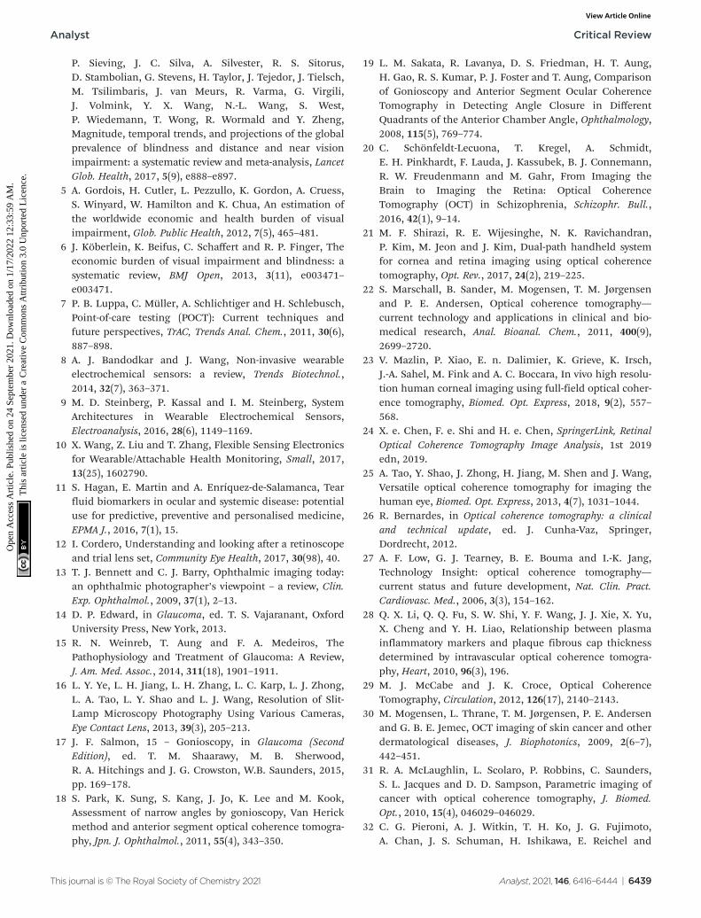
P. Sieving, J. C. Silva, A. Silvester, R. S. Sitorus,D. Stambolian, G. Stevens, H. Taylor, J. Tejedor, J. Tielsch,M. Tsilimbaris, J. van Meurs, R. Varma, G. Virgili,J. Volmink, Y. X. Wang, N.-L. Wang, S. West,P. Wiedemann, T. Wong, R. Wormald and Y. Zheng,Magnitude, temporal trends, and projections of the globalprevalence of blindness and distance and near visionimpairment: a systematic review and meta-analysis, LancetGlob. Health, 2017, 5(9), e888–e897.
5 A. Gordois, H. Cutler, L. Pezzullo, K. Gordon, A. Cruess,S. Winyard, W. Hamilton and K. Chua, An estimation ofthe worldwide economic and health burden of visualimpairment, Glob. Public Health, 2012, 7(5), 465–481.
6 J. Köberlein, K. Beifus, C. Schaffert and R. P. Finger, Theeconomic burden of visual impairment and blindness: asystematic review, BMJ Open, 2013, 3(11), e003471–e003471.
7 P. B. Luppa, C. Müller, A. Schlichtiger and H. Schlebusch,Point-of-care testing (POCT): Current techniques andfuture perspectives, TrAC, Trends Anal. Chem., 2011, 30(6),887–898.
8 A. J. Bandodkar and J. Wang, Non-invasive wearableelectrochemical sensors: a review, Trends Biotechnol.,2014, 32(7), 363–371.
9 M. D. Steinberg, P. Kassal and I. M. Steinberg, SystemArchitectures in Wearable Electrochemical Sensors,Electroanalysis, 2016, 28(6), 1149–1169.
10 X. Wang, Z. Liu and T. Zhang, Flexible Sensing Electronicsfor Wearable/Attachable Health Monitoring, Small, 2017,13(25), 1602790.
11 S. Hagan, E. Martin and A. Enríquez-de-Salamanca, Tearfluid biomarkers in ocular and systemic disease: potentialuse for predictive, preventive and personalised medicine,EPMA J., 2016, 7(1), 15.
12 I. Cordero, Understanding and looking after a retinoscopeand trial lens set, Community Eye Health, 2017, 30(98), 40.
13 T. J. Bennett and C. J. Barry, Ophthalmic imaging today:an ophthalmic photographer’s viewpoint – a review, Clin.Exp. Ophthalmol., 2009, 37(1), 2–13.
14 D. P. Edward, in Glaucoma, ed. T. S. Vajaranant, OxfordUniversity Press, New York, 2013.
15 R. N. Weinreb, T. Aung and F. A. Medeiros, ThePathophysiology and Treatment of Glaucoma: A Review,J. Am. Med. Assoc., 2014, 311(18), 1901–1911.
16 L. Y. Ye, L. H. Jiang, L. H. Zhang, L. C. Karp, L. J. Zhong,L. A. Tao, L. Y. Shao and L. J. Wang, Resolution of Slit-Lamp Microscopy Photography Using Various Cameras,Eye Contact Lens, 2013, 39(3), 205–213.
17 J. F. Salmon, 15 – Gonioscopy, in Glaucoma (SecondEdition), ed. T. M. Shaarawy, M. B. Sherwood,R. A. Hitchings and J. G. Crowston, W.B. Saunders, 2015,pp. 169–178.
18 S. Park, K. Sung, S. Kang, J. Jo, K. Lee and M. Kook,Assessment of narrow angles by gonioscopy, Van Herickmethod and anterior segment optical coherence tomogra-phy, Jpn. J. Ophthalmol., 2011, 55(4), 343–350.
19 L. M. Sakata, R. Lavanya, D. S. Friedman, H. T. Aung,H. Gao, R. S. Kumar, P. J. Foster and T. Aung, Comparisonof Gonioscopy and Anterior Segment Ocular CoherenceTomography in Detecting Angle Closure in DifferentQuadrants of the Anterior Chamber Angle, Ophthalmology,2008, 115(5), 769–774.
20 C. Schönfeldt-Lecuona, T. Kregel, A. Schmidt,E. H. Pinkhardt, F. Lauda, J. Kassubek, B. J. Connemann,R. W. Freudenmann and M. Gahr, From Imaging theBrain to Imaging the Retina: Optical CoherenceTomography (OCT) in Schizophrenia, Schizophr. Bull.,2016, 42(1), 9–14.
21 M. F. Shirazi, R. E. Wijesinghe, N. K. Ravichandran,P. Kim, M. Jeon and J. Kim, Dual-path handheld systemfor cornea and retina imaging using optical coherencetomography, Opt. Rev., 2017, 24(2), 219–225.
22 S. Marschall, B. Sander, M. Mogensen, T. M. Jørgensenand P. E. Andersen, Optical coherence tomography—current technology and applications in clinical and bio-medical research, Anal. Bioanal. Chem., 2011, 400(9),2699–2720.
23 V. Mazlin, P. Xiao, E. n. Dalimier, K. Grieve, K. Irsch,J.-A. Sahel, M. Fink and A. C. Boccara, In vivo high resolu-tion human corneal imaging using full-field optical coher-ence tomography, Biomed. Opt. Express, 2018, 9(2), 557–568.
24 X. e. Chen, F. e. Shi and H. e. Chen, SpringerLink, RetinalOptical Coherence Tomography Image Analysis, 1st 2019edn, 2019.
25 A. Tao, Y. Shao, J. Zhong, H. Jiang, M. Shen and J. Wang,Versatile optical coherence tomography for imaging thehuman eye, Biomed. Opt. Express, 2013, 4(7), 1031–1044.
26 R. Bernardes, in Optical coherence tomography: a clinicaland technical update, ed. J. Cunha-Vaz, Springer,Dordrecht, 2012.
27 A. F. Low, G. J. Tearney, B. E. Bouma and I.-K. Jang,Technology Insight: optical coherence tomography—current status and future development, Nat. Clin. Pract.Cardiovasc. Med., 2006, 3(3), 154–162.
28 Q. X. Li, Q. Q. Fu, S. W. Shi, Y. F. Wang, J. J. Xie, X. Yu,X. Cheng and Y. H. Liao, Relationship between plasmainflammatory markers and plaque fibrous cap thicknessdetermined by intravascular optical coherence tomogra-phy, Heart, 2010, 96(3), 196.
29 M. J. McCabe and J. K. Croce, Optical CoherenceTomography, Circulation, 2012, 126(17), 2140–2143.
30 M. Mogensen, L. Thrane, T. M. Jørgensen, P. E. Andersenand G. B. E. Jemec, OCT imaging of skin cancer and otherdermatological diseases, J. Biophotonics, 2009, 2(6–7),442–451.
31 R. A. McLaughlin, L. Scolaro, P. Robbins, C. Saunders,S. L. Jacques and D. D. Sampson, Parametric imaging ofcancer with optical coherence tomography, J. Biomed.Opt., 2010, 15(4), 046029–046029.
32 C. G. Pieroni, A. J. Witkin, T. H. Ko, J. G. Fujimoto,A. Chan, J. S. Schuman, H. Ishikawa, E. Reichel and
Analyst Critical Review
This journal is © The Royal Society of Chemistry 2021 Analyst, 2021, 146, 6416–6444 | 6439
Ope
n A
cces
s A
rtic
le. P
ublis
hed
on 2
4 Se
ptem
ber
2021
. Dow
nloa
ded
on 1
/17/
2022
12:
33:5
9 A
M.
Thi
s ar
ticle
is li
cens
ed u
nder
a C
reat
ive
Com
mon
s A
ttrib
utio
n 3.
0 U
npor
ted
Lic
ence
.View Article Online
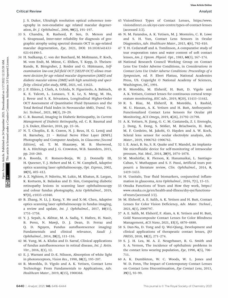
J. S. Duker, Ultrahigh resolution optical coherence tom-ography in non-exudative age related macular degener-ation, Br. J. Ophthalmol., 2006, 90(2), 191–197.
33 S. Chandra, R. Rasheed, P. Sen, D. Menon andS. Sivaprasad, Inter-rater reliability for diagnosis of geo-graphic atrophy using spectral domain OCT in age-relatedmacular degeneration, Eye, 2021, DOI: 10.1038/s41433-021-01490-5.
34 H. Sudkamp, C. von der Burchard, M. Moltmann, P. Koch,M. vom Endt, M. Münst, C. Ehlken, T. Kepp, D. Theisen-Kunde, R. Birngruber, J. Roider and G. Hüttmann, Self-examination low-cost full-field OCT (SELFF-OCT) allows treat-ment decision for age related macular degeneration (AMD) anddiabetic macular edema (DME) with high sensitivity and speci-ficity: clinical pilot study, SPIE, 2021, vol. 11623.
35 J. P. Ehlers, J. Clark, A. Uchida, N. Figueiredo, A. Babiuch,K. E. Talcott, L. Lunasco, T. K. Le, X. Meng, M. Hu,J. Reese and S. K. Srivastava, Longitudinal Higher-OrderOCT Assessment of Quantitative Fluid Dynamics and theTotal Retinal Fluid Index in Neovascular AMD, Transl. Vis.Sci. Technol., 2021, 10(3), 29–29.
36 C. R. Baumal, Imaging in Diabetic Retinopathy, in CurrentManagement of Diabetic Retinopathy, ed. C. R. Baumal andJ. S. Duker, Elsevier, 2018, pp. 25–36.
37 N. T. Choplin, E. R. Craven, N. J. Reus, H. G. Lemij andH. Barnebey, 21 – Retinal Nerve Fiber Layer (RNFL)Photography and Computer Analysis, in Glaucoma (SecondEdition), ed. T. M. Shaarawy, M. B. Sherwood,R. A. Hitchings and J. G. Crowston, W.B. Saunders, 2015,pp. 244–260.
38 A. Roorda, F. Romero-Borja, W. J. Donnelly III,H. Queener, T. J. Hebert and M. C. W. Campbell, Adaptiveoptics scanning laser ophthalmoscopy, Opt. Express, 2002,10(9), 405–412.
39 A. Z. Nghiem, P. Nderitu, M. Lukic, M. Khatun, R. Largan,K. Kortuem, K. Balaskas and D. Sim, Comparing diabeticretinopathy lesions in scanning laser ophthalmoscopyand colour fundus photography, Acta Ophthalmol., 2019,97(8), e1035–e1040.
40 B. Zhang, N. Li, J. Kang, Y. He and X.-M. Chen, Adaptiveoptics scanning laser ophthalmoscopy in fundus imaging,a review and update, Int. J. Ophthalmol., 2017, 10(11),1751–1758.
41 Y. J. Sepah, A. Akhtar, M. A. Sadiq, Y. Hafeez, H. Nasir,B. Perez, N. Mawji, D. J. Dean, D. Ferraz andQ. D. Nguyen, Fundus autofluorescence imaging:Fundamentals and clinical relevance, Saudi J.Ophthalmol., 2014, 28(2), 111–116.
42 M. Yung, M. A. Klufas and D. Sarraf, Clinical applicationsof fundus autofluorescence in retinal disease, Int. J. Retin.Vitr., 2016, 2(1), 12.
43 E. J. Warrant and D.-E. Nilsson, Absorption of white lightin photoreceptors, Vision Res., 1998, 38(2), 195–207.
44 R. Moreddu, D. Vigolo and A. K. Yetisen, Contact LensTechnology: From Fundamentals to Applications, Adv.Healthcare Mater., 2019, 8(15), 1900368.
45 VisionDirect Types of Contact Lenses, https://www.visiondirect.co.uk/eye-care-centre/types-of-contact-lenses(accessed 3/2).
46 N. M. Farandos, A. K. Yetisen, M. J. Monteiro, C. R. Loweand S. H. Yun, Contact Lens Sensors in OcularDiagnostics, Adv. Healthcare Mater., 2015, 4(6), 792–810.
47 T. H. Cedarstaff and A. Tomlinson, A comparative study oftear evaporation rates and water content of soft contactlenses, Am. J. Optom. Physiol. Opt., 1983, 60(3), 167–174.
48 National Research Council Working Group on ContactLens Use Under Adverse Conditions, in Considerations inContact Lens Use Under Adverse Conditions: Proceedings of aSymposium, ed. P. Ebert Flattau, National AcademiesPress, US. Copyright © National Academy of Sciences,Washington, DC, 1991.
49 R. Moreddu, M. Elsherif, H. Butt, D. Vigolo andA. K. Yetisen, Contact lenses for continuous corneal temp-erature monitoring, RSC Adv., 2019, 9(20), 11433–11442.
50 R. S. Riaz, M. Elsherif, R. Moreddu, I. Rashid,M. U. Hassan, A. K. Yetisen and H. Butt, Anthocyanin-Functionalized Contact Lens Sensors for Ocular pHMonitoring, ACS Omega, 2019, 4(26), 21792–21798.
51 A. K. Yetisen, N. Jiang, G. C. M. Castaneda, Z. I. Erenoglu,J. Dong, X. Dong, S. Stößer, M. Brischwein, H. Butt,M. F. Cordeiro, M. Jakobi, O. Hayden and A. W. Koch,Scleral lens sensor for ocular electrolyte analysis, Adv.Mater., 2019, 1906762–1906762.
52 I. E. Araci, B. Su, S. R. Quake and Y. Mandel, An implanta-ble microfluidic device for self-monitoring of intraocularpressure, Nat. Med., 2014, 20(9), 1074–1078.
53 M. Moshirfar, K. Pierson, K. Hanamaikai, L. Santiago-Caban, V. Muthappan and S. F. Passi, Artificial tears pot-pourri: a literature review, Clin. Ophthalmol., 2014, 8,1419–1433.
54 H. Uusitalo, Tear fluid biomarkers, conjunctival inflam-mation in glaucoma, Acta Ophthalmol., 2016, 7(1), 15–15.
55 Otsuka Functions of Tears and How they work, https://www.otsuka.co.jp/en/health-and-illness/dry-eye/functions-of-tears/(accessed 3/2).
56 M. Elsherif, A. E. Salih, A. K. Yetisen and H. Butt, ContactLenses for Color Vision Deficiency, Adv. Mater. Technol.,2021, 6(1), 2000797.
57 A. E. Salih, M. Elsherif, F. Alam, A. K. Yetisen and H. Butt,Gold Nanocomposite Contact Lenses for Color BlindnessManagement, ACS Nano, 2021, 15(3), 4870–4880.
58 S. Dan-Na, D. Tong and Q. Wei-Qiang, Development andclinical applications of therapeutic contact lenses, IJOPRESS, 2018, 18(2), 271–274.
59 S. J. H. Lea, M. A. Z. Neugebauer, R. G. Smith andS. A. Vernon, The incidence of ophthalmic problems inthe contact lens wearing population, Eye, 1990, 4(5), 706–711.
60 A. K. Dumbleton, W. C. Woods, W. L. Jones andW. D. Fonn, The Impact of Contemporary Contact Lenseson Contact Lens Discontinuation, Eye Contact Lens, 2013,39(1), 93–99.
Critical Review Analyst
6440 | Analyst, 2021, 146, 6416–6444 This journal is © The Royal Society of Chemistry 2021
Ope
n A
cces
s A
rtic
le. P
ublis
hed
on 2
4 Se
ptem
ber
2021
. Dow
nloa
ded
on 1
/17/
2022
12:
33:5
9 A
M.
Thi
s ar
ticle
is li
cens
ed u
nder
a C
reat
ive
Com
mon
s A
ttrib
utio
n 3.
0 U
npor
ted
Lic
ence
.View Article Online
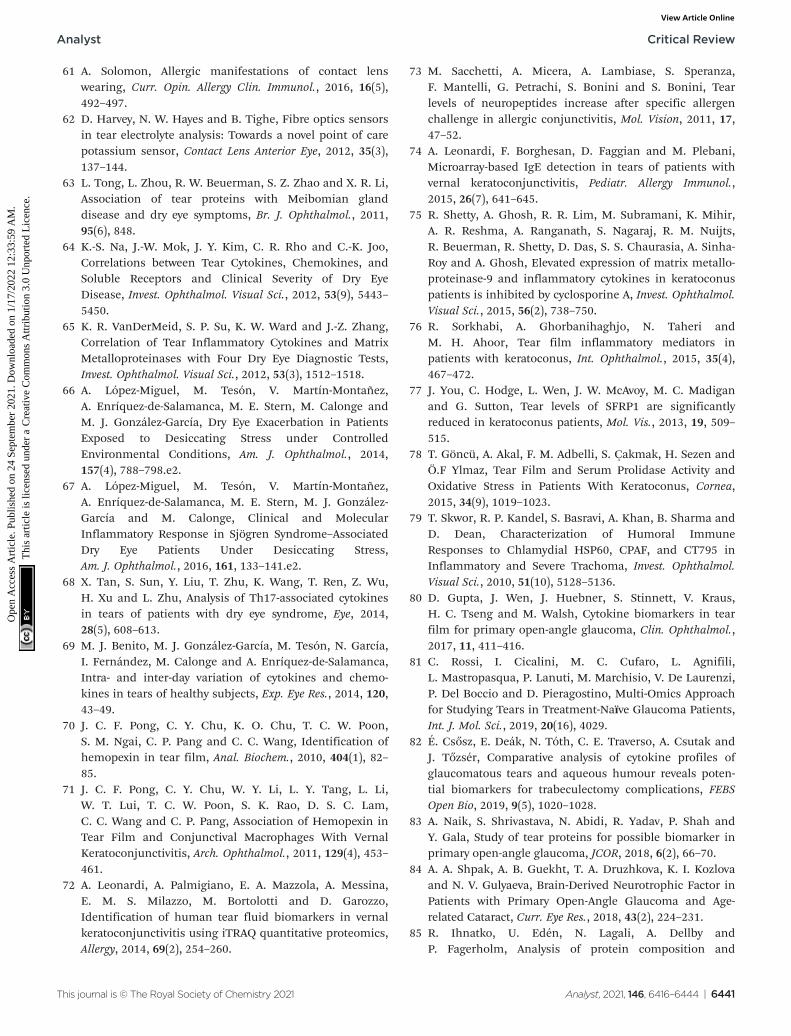
61 A. Solomon, Allergic manifestations of contact lenswearing, Curr. Opin. Allergy Clin. Immunol., 2016, 16(5),492–497.
62 D. Harvey, N. W. Hayes and B. Tighe, Fibre optics sensorsin tear electrolyte analysis: Towards a novel point of carepotassium sensor, Contact Lens Anterior Eye, 2012, 35(3),137–144.
63 L. Tong, L. Zhou, R. W. Beuerman, S. Z. Zhao and X. R. Li,Association of tear proteins with Meibomian glanddisease and dry eye symptoms, Br. J. Ophthalmol., 2011,95(6), 848.
64 K.-S. Na, J.-W. Mok, J. Y. Kim, C. R. Rho and C.-K. Joo,Correlations between Tear Cytokines, Chemokines, andSoluble Receptors and Clinical Severity of Dry EyeDisease, Invest. Ophthalmol. Visual Sci., 2012, 53(9), 5443–5450.
65 K. R. VanDerMeid, S. P. Su, K. W. Ward and J.-Z. Zhang,Correlation of Tear Inflammatory Cytokines and MatrixMetalloproteinases with Four Dry Eye Diagnostic Tests,Invest. Ophthalmol. Visual Sci., 2012, 53(3), 1512–1518.
66 A. López-Miguel, M. Tesón, V. Martín-Montañez,A. Enríquez-de-Salamanca, M. E. Stern, M. Calonge andM. J. González-García, Dry Eye Exacerbation in PatientsExposed to Desiccating Stress under ControlledEnvironmental Conditions, Am. J. Ophthalmol., 2014,157(4), 788–798.e2.
67 A. López-Miguel, M. Tesón, V. Martín-Montañez,A. Enríquez-de-Salamanca, M. E. Stern, M. J. González-García and M. Calonge, Clinical and MolecularInflammatory Response in Sjögren Syndrome–AssociatedDry Eye Patients Under Desiccating Stress,Am. J. Ophthalmol., 2016, 161, 133–141.e2.
68 X. Tan, S. Sun, Y. Liu, T. Zhu, K. Wang, T. Ren, Z. Wu,H. Xu and L. Zhu, Analysis of Th17-associated cytokinesin tears of patients with dry eye syndrome, Eye, 2014,28(5), 608–613.
69 M. J. Benito, M. J. González-García, M. Tesón, N. García,I. Fernández, M. Calonge and A. Enríquez-de-Salamanca,Intra- and inter-day variation of cytokines and chemo-kines in tears of healthy subjects, Exp. Eye Res., 2014, 120,43–49.
70 J. C. F. Pong, C. Y. Chu, K. O. Chu, T. C. W. Poon,S. M. Ngai, C. P. Pang and C. C. Wang, Identification ofhemopexin in tear film, Anal. Biochem., 2010, 404(1), 82–85.
71 J. C. F. Pong, C. Y. Chu, W. Y. Li, L. Y. Tang, L. Li,W. T. Lui, T. C. W. Poon, S. K. Rao, D. S. C. Lam,C. C. Wang and C. P. Pang, Association of Hemopexin inTear Film and Conjunctival Macrophages With VernalKeratoconjunctivitis, Arch. Ophthalmol., 2011, 129(4), 453–461.
72 A. Leonardi, A. Palmigiano, E. A. Mazzola, A. Messina,E. M. S. Milazzo, M. Bortolotti and D. Garozzo,Identification of human tear fluid biomarkers in vernalkeratoconjunctivitis using iTRAQ quantitative proteomics,Allergy, 2014, 69(2), 254–260.
73 M. Sacchetti, A. Micera, A. Lambiase, S. Speranza,F. Mantelli, G. Petrachi, S. Bonini and S. Bonini, Tearlevels of neuropeptides increase after specific allergenchallenge in allergic conjunctivitis, Mol. Vision, 2011, 17,47–52.
74 A. Leonardi, F. Borghesan, D. Faggian and M. Plebani,Microarray-based IgE detection in tears of patients withvernal keratoconjunctivitis, Pediatr. Allergy Immunol.,2015, 26(7), 641–645.
75 R. Shetty, A. Ghosh, R. R. Lim, M. Subramani, K. Mihir,A. R. Reshma, A. Ranganath, S. Nagaraj, R. M. Nuijts,R. Beuerman, R. Shetty, D. Das, S. S. Chaurasia, A. Sinha-Roy and A. Ghosh, Elevated expression of matrix metallo-proteinase-9 and inflammatory cytokines in keratoconuspatients is inhibited by cyclosporine A, Invest. Ophthalmol.Visual Sci., 2015, 56(2), 738–750.
76 R. Sorkhabi, A. Ghorbanihaghjo, N. Taheri andM. H. Ahoor, Tear film inflammatory mediators inpatients with keratoconus, Int. Ophthalmol., 2015, 35(4),467–472.
77 J. You, C. Hodge, L. Wen, J. W. McAvoy, M. C. Madiganand G. Sutton, Tear levels of SFRP1 are significantlyreduced in keratoconus patients, Mol. Vis., 2013, 19, 509–515.
78 T. Göncü, A. Akal, F. M. Adbelli, S. Çakmak, H. Sezen andÖ.F Ylmaz, Tear Film and Serum Prolidase Activity andOxidative Stress in Patients With Keratoconus, Cornea,2015, 34(9), 1019–1023.
79 T. Skwor, R. P. Kandel, S. Basravi, A. Khan, B. Sharma andD. Dean, Characterization of Humoral ImmuneResponses to Chlamydial HSP60, CPAF, and CT795 inInflammatory and Severe Trachoma, Invest. Ophthalmol.Visual Sci., 2010, 51(10), 5128–5136.
80 D. Gupta, J. Wen, J. Huebner, S. Stinnett, V. Kraus,H. C. Tseng and M. Walsh, Cytokine biomarkers in tearfilm for primary open-angle glaucoma, Clin. Ophthalmol.,2017, 11, 411–416.
81 C. Rossi, I. Cicalini, M. C. Cufaro, L. Agnifili,L. Mastropasqua, P. Lanuti, M. Marchisio, V. De Laurenzi,P. Del Boccio and D. Pieragostino, Multi-Omics Approachfor Studying Tears in Treatment-Naïve Glaucoma Patients,Int. J. Mol. Sci., 2019, 20(16), 4029.
82 É. Csősz, E. Deák, N. Tóth, C. E. Traverso, A. Csutak andJ. Tőzsér, Comparative analysis of cytokine profiles ofglaucomatous tears and aqueous humour reveals poten-tial biomarkers for trabeculectomy complications, FEBSOpen Bio, 2019, 9(5), 1020–1028.
83 A. Naik, S. Shrivastava, N. Abidi, R. Yadav, P. Shah andY. Gala, Study of tear proteins for possible biomarker inprimary open-angle glaucoma, JCOR, 2018, 6(2), 66–70.
84 A. A. Shpak, A. B. Guekht, T. A. Druzhkova, K. I. Kozlovaand N. V. Gulyaeva, Brain-Derived Neurotrophic Factor inPatients with Primary Open-Angle Glaucoma and Age-related Cataract, Curr. Eye Res., 2018, 43(2), 224–231.
85 R. Ihnatko, U. Edén, N. Lagali, A. Dellby andP. Fagerholm, Analysis of protein composition and
Analyst Critical Review
This journal is © The Royal Society of Chemistry 2021 Analyst, 2021, 146, 6416–6444 | 6441
Ope
n A
cces
s A
rtic
le. P
ublis
hed
on 2
4 Se
ptem
ber
2021
. Dow
nloa
ded
on 1
/17/
2022
12:
33:5
9 A
M.
Thi
s ar
ticle
is li
cens
ed u
nder
a C
reat
ive
Com
mon
s A
ttrib
utio
n 3.
0 U
npor
ted
Lic
ence
.View Article Online
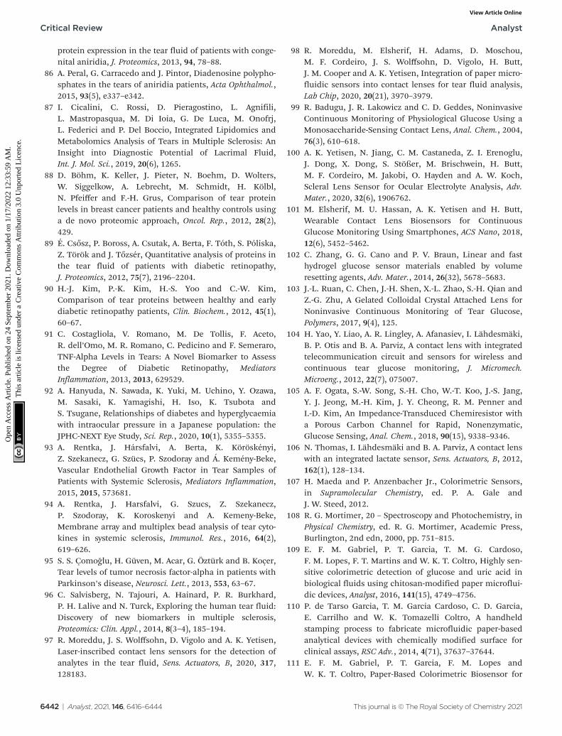
protein expression in the tear fluid of patients with conge-nital aniridia, J. Proteomics, 2013, 94, 78–88.
86 A. Peral, G. Carracedo and J. Pintor, Diadenosine polypho-sphates in the tears of aniridia patients, Acta Ophthalmol.,2015, 93(5), e337–e342.
87 I. Cicalini, C. Rossi, D. Pieragostino, L. Agnifili,L. Mastropasqua, M. Di Ioia, G. De Luca, M. Onofrj,L. Federici and P. Del Boccio, Integrated Lipidomics andMetabolomics Analysis of Tears in Multiple Sclerosis: AnInsight into Diagnostic Potential of Lacrimal Fluid,Int. J. Mol. Sci., 2019, 20(6), 1265.
88 D. Böhm, K. Keller, J. Pieter, N. Boehm, D. Wolters,W. Siggelkow, A. Lebrecht, M. Schmidt, H. Kölbl,N. Pfeiffer and F.-H. Grus, Comparison of tear proteinlevels in breast cancer patients and healthy controls usinga de novo proteomic approach, Oncol. Rep., 2012, 28(2),429.
89 É. Csősz, P. Boross, A. Csutak, A. Berta, F. Tóth, S. Póliska,Z. Török and J. Tőzsér, Quantitative analysis of proteins inthe tear fluid of patients with diabetic retinopathy,J. Proteomics, 2012, 75(7), 2196–2204.
90 H.-J. Kim, P.-K. Kim, H.-S. Yoo and C.-W. Kim,Comparison of tear proteins between healthy and earlydiabetic retinopathy patients, Clin. Biochem., 2012, 45(1),60–67.
91 C. Costagliola, V. Romano, M. De Tollis, F. Aceto,R. dell’Omo, M. R. Romano, C. Pedicino and F. Semeraro,TNF-Alpha Levels in Tears: A Novel Biomarker to Assessthe Degree of Diabetic Retinopathy, MediatorsInflammation, 2013, 2013, 629529.
92 A. Hanyuda, N. Sawada, K. Yuki, M. Uchino, Y. Ozawa,M. Sasaki, K. Yamagishi, H. Iso, K. Tsubota andS. Tsugane, Relationships of diabetes and hyperglycaemiawith intraocular pressure in a Japanese population: theJPHC-NEXT Eye Study, Sci. Rep., 2020, 10(1), 5355–5355.
93 A. Rentka, J. Hársfalvi, A. Berta, K. Köröskényi,Z. Szekanecz, G. Szücs, P. Szodoray and Á. Kemény-Beke,Vascular Endothelial Growth Factor in Tear Samples ofPatients with Systemic Sclerosis, Mediators Inflammation,2015, 2015, 573681.
94 A. Rentka, J. Harsfalvi, G. Szucs, Z. Szekanecz,P. Szodoray, K. Koroskenyi and A. Kemeny-Beke,Membrane array and multiplex bead analysis of tear cyto-kines in systemic sclerosis, Immunol. Res., 2016, 64(2),619–626.
95 S. S. Çomoğlu, H. Güven, M. Acar, G. Öztürk and B. Koçer,Tear levels of tumor necrosis factor-alpha in patients withParkinson’s disease, Neurosci. Lett., 2013, 553, 63–67.
96 C. Salvisberg, N. Tajouri, A. Hainard, P. R. Burkhard,P. H. Lalive and N. Turck, Exploring the human tear fluid:Discovery of new biomarkers in multiple sclerosis,Proteomics: Clin. Appl., 2014, 8(3–4), 185–194.
97 R. Moreddu, J. S. Wolffsohn, D. Vigolo and A. K. Yetisen,Laser-inscribed contact lens sensors for the detection ofanalytes in the tear fluid, Sens. Actuators, B, 2020, 317,128183.
98 R. Moreddu, M. Elsherif, H. Adams, D. Moschou,M. F. Cordeiro, J. S. Wolffsohn, D. Vigolo, H. Butt,J. M. Cooper and A. K. Yetisen, Integration of paper micro-fluidic sensors into contact lenses for tear fluid analysis,Lab Chip, 2020, 20(21), 3970–3979.
99 R. Badugu, J. R. Lakowicz and C. D. Geddes, NoninvasiveContinuous Monitoring of Physiological Glucose Using aMonosaccharide-Sensing Contact Lens, Anal. Chem., 2004,76(3), 610–618.
100 A. K. Yetisen, N. Jiang, C. M. Castaneda, Z. I. Erenoglu,J. Dong, X. Dong, S. Stößer, M. Brischwein, H. Butt,M. F. Cordeiro, M. Jakobi, O. Hayden and A. W. Koch,Scleral Lens Sensor for Ocular Electrolyte Analysis, Adv.Mater., 2020, 32(6), 1906762.
101 M. Elsherif, M. U. Hassan, A. K. Yetisen and H. Butt,Wearable Contact Lens Biosensors for ContinuousGlucose Monitoring Using Smartphones, ACS Nano, 2018,12(6), 5452–5462.
102 C. Zhang, G. G. Cano and P. V. Braun, Linear and fasthydrogel glucose sensor materials enabled by volumeresetting agents, Adv. Mater., 2014, 26(32), 5678–5683.
103 J.-L. Ruan, C. Chen, J.-H. Shen, X.-L. Zhao, S.-H. Qian andZ.-G. Zhu, A Gelated Colloidal Crystal Attached Lens forNoninvasive Continuous Monitoring of Tear Glucose,Polymers, 2017, 9(4), 125.
104 H. Yao, Y. Liao, A. R. Lingley, A. Afanasiev, I. Lähdesmäki,B. P. Otis and B. A. Parviz, A contact lens with integratedtelecommunication circuit and sensors for wireless andcontinuous tear glucose monitoring, J. Micromech.Microeng., 2012, 22(7), 075007.
105 A. F. Ogata, S.-W. Song, S.-H. Cho, W.-T. Koo, J.-S. Jang,Y. J. Jeong, M.-H. Kim, J. Y. Cheong, R. M. Penner andI.-D. Kim, An Impedance-Transduced Chemiresistor witha Porous Carbon Channel for Rapid, Nonenzymatic,Glucose Sensing, Anal. Chem., 2018, 90(15), 9338–9346.
106 N. Thomas, I. Lähdesmäki and B. A. Parviz, A contact lenswith an integrated lactate sensor, Sens. Actuators, B, 2012,162(1), 128–134.
107 H. Maeda and P. Anzenbacher Jr., Colorimetric Sensors,in Supramolecular Chemistry, ed. P. A. Gale andJ. W. Steed, 2012.
108 R. G. Mortimer, 20 – Spectroscopy and Photochemistry, inPhysical Chemistry, ed. R. G. Mortimer, Academic Press,Burlington, 2nd edn, 2000, pp. 751–815.
109 E. F. M. Gabriel, P. T. Garcia, T. M. G. Cardoso,F. M. Lopes, F. T. Martins and W. K. T. Coltro, Highly sen-sitive colorimetric detection of glucose and uric acid inbiological fluids using chitosan-modified paper microflui-dic devices, Analyst, 2016, 141(15), 4749–4756.
110 P. de Tarso Garcia, T. M. Garcia Cardoso, C. D. Garcia,E. Carrilho and W. K. Tomazelli Coltro, A handheldstamping process to fabricate microfluidic paper-basedanalytical devices with chemically modified surface forclinical assays, RSC Adv., 2014, 4(71), 37637–37644.
111 E. F. M. Gabriel, P. T. Garcia, F. M. Lopes andW. K. T. Coltro, Paper-Based Colorimetric Biosensor for
Critical Review Analyst
6442 | Analyst, 2021, 146, 6416–6444 This journal is © The Royal Society of Chemistry 2021
Ope
n A
cces
s A
rtic
le. P
ublis
hed
on 2
4 Se
ptem
ber
2021
. Dow
nloa
ded
on 1
/17/
2022
12:
33:5
9 A
M.
Thi
s ar
ticle
is li
cens
ed u
nder
a C
reat
ive
Com
mon
s A
ttrib
utio
n 3.
0 U
npor
ted
Lic
ence
.View Article Online
Tear Glucose Measurements, Micromachines, 2017, 8(4),104.
112 C. M. Cheng, A. W. Martinez, J. Gong, C. R. Mace,S. T. Phillips, E. Carrilho, K. A. Mirica andG. M. Whitesides, Paper-based ELISA, Angew. Chem., Int.Ed. Engl., 2010, 49(28), 4771–4774.
113 J. Hu, S. Wang, L. Wang, F. Li, B. Pingguan-Murphy,T. J. Lu and F. Xu, Advances in paper-based point-of-carediagnostics, Biosens. Bioelectron., 2014, 54, 585–597.
114 M.-Y. Hsu, C.-Y. Yang, W.-H. Hsu, K.-H. Lin, C.-Y. Wang,Y.-C. Shen, Y.-C. Chen, S.-F. Chau, H.-Y. Tsai andC.-M. Cheng, Monitoring the VEGF level in aqueoushumor of patients with ophthalmologically relevant dis-eases via ultrahigh sensitive paper-based ELISA,Biomaterials, 2014, 35(12), 3729–3735.
115 X. Zhu, S. Xiong, J. Zhang, X. Zhang, X. Tong and S. Kong,Improving paper-based ELISA performance throughcovalent immobilization of antibodies, Sens. Actuators, B,2018, 255, 598–604.
116 A. Ghaffariyeh, N. Honarpisheh, Y. Shakiba, S. Puyan,T. Chamacham, F. Zahedi and M. Zarrineghbal, Brain-derived neurotrophic factor in patients with normal-tension glaucoma, Optometry – J. Am. Optom. Assoc., 2009,80(11), 635–638.
117 C. E. Wayne, Photochemistry, Oxford University Press,Oxford, New York, 1996.
118 R. Badugu, B. H. Jeng, E. A. Reece and J. R. Lakowicz,Contact lens to measure individual ion concentrations intears and applications to dry eye disease, Anal. Biochem.,2018, 542, 84–94.
119 R. Badugu, H. Szmacinski, E. A. Reece, B. H. Jeng andJ. R. Lakowicz, Fluorescent Contact Lens for ContinuousNon-invasive Measurements of Sodium and ChlorideIon Concentrations in Tears, Anal. Biochem., 2020,113902.
120 R. Badugu, E. A. Reece and J. Lakowicz, Glucose-sensitivesilicone hydrogel contact lens toward tear glucose moni-toring, J. Biomed. Opt., 2018, 23(5), 057005.
121 K. Maejima, S. Tomikawa, K. Suzuki and D. Citterio,Inkjet printing: an integrated and green chemicalapproach to microfluidic paper-based analytical devices,RSC Adv., 2013, 3(24), 9258–9263.
122 K. Yamada, T. G. Henares, K. Suzuki and D. Citterio,Distance-Based Tear Lactoferrin Assay on MicrofluidicPaper Device Using Interfacial Interactions on Surface-Modified Cellulose, ACS Appl. Mater. Interfaces, 2015,7(44), 24864–24875.
123 H. Yao, A. J. Shum, M. Cowan, I. Lähdesmäki andB. A. Parviz, A contact lens with embedded sensor formonitoring tear glucose level, Biosens. Bioelectron., 2011,26(7), 3290–3296.
124 H. Yao, Y. Liao, A. R. Lingley, A. Afanasiev, I. Lähdesmäki,B. P. Otis and B. A. Parviz, A contact lens with integratedtelecommunication circuit and sensors for wireless andcontinuous tear glucose monitoring, J. Micromech.Microeng., 2012, 22(7), 075007.
125 M. Chu, T. Shirai, D. Takahashi, T. Arakawa, H. Kudo,K. Sano, S.-i. Sawada, K. Yano, Y. Iwasaki, K. Akiyoshi,M. Mochizuki and K. Mitsubayashi, Biomedical softcontact-lens sensor for in situ ocular biomonitoring oftear contents, Biomed. Microdevices, 2011, 13(4), 603–611.
126 M. X. Chu, K. Miyajima, D. Takahashi, T. Arakawa,K. Sano, S.-i. Sawada, H. Kudo, Y. Iwasaki, K. Akiyoshi,M. Mochizuki and K. Mitsubayashi, Soft contact lens bio-sensor for in situ monitoring of tear glucose as non-inva-sive blood sugar assessment, Talanta, 2011, 83(3), 960–965.
127 J. Kim, M. Kim, M.-S. Lee, K. Kim, S. Ji, Y.-T. Kim, J. Park,K. Na, K.-H. Bae, H. Kyun Kim, F. Bien, C. Young Lee andJ.-U. Park, Wearable smart sensor systems integrated onsoft contact lenses for wireless ocular diagnostics, Nat.Commun., 2017, 8(1), 14997.
128 M. Ku, J. Kim, J.-e. Won, W. Kang, Y.-G. Park, J. Park,J.-H. Lee, J. Cheon, H. Lee and J.-U. Park, Smart, softcontact lens for wireless immunosensing of cortisol, Sci.Adv., 2020, 6(28), eabb2891.
129 J. Kim, J. Park, Y.-G. Park, E. Cha, M. Ku, H. S. An,K.-P. Lee, M.-I. Huh, J. Kim, T.-S. Kim, D. W. Kim,H. K. Kim and J.-U. Park, A soft and transparent contactlens for the wireless quantitative monitoring ofintraocular pressure, Nat. Biomed. Eng., 2021, 5(7), 772–782.
130 J. Kim, J. Kim, M. Ku, E. Cha, S. Ju, W. Y. Park, K. H. Kim,D. W. Kim, P.-O. Berggren and J.-U. Park, IntraocularPressure Monitoring Following Islet Transplantation tothe Anterior Chamber of the Eye, Nano Lett., 2020, 20(3),1517–1525.
131 J. Jang, J. Kim, H. Shin, Y. G. Park, B. J. Joo, H. Seo,J. E. Won, D. W. Kim, C. Y. Lee, H. K. Kim and J. U. Park,Smart contact lens and transparent heat patch for remotemonitoring and therapy of chronic ocular surface inflam-mation using mobiles, Sci. Adv., 2021, 7(14), eabf7194.
132 S. Kim, H.-J. Jeon, S. Park, D. Y. Lee and E. Chung, TearGlucose Measurement by Reflectance Spectrum of aNanoparticle Embedded Contact Lens, Sci. Rep., 2020,10(1), 8254.
133 M. Donora, A. Vásquez Quintero, H. De Smet andI. Underwood, Spatiotemporal electrochemical sensing ina smart contact lens, Sens. Actuators, B, 2020, 303, 127203.
134 K. Kim, H. J. Kim, H. Zhang, W. Park, D. Meyer,M. K. Kim, B. Kim, H. Park, B. Xu, P. Kollbaum,B. W. Boudouris and C. H. Lee, All-printed stretchablecorneal sensor on soft contact lenses for noninvasive andpainless ocular electrodiagnosis, Nat. Commun., 2021,12(1), 1544.
135 C. Zhang, M. D. Losego and P. V. Braun, Hydrogel-BasedGlucose Sensors: Effects of Phenylboronic Acid ChemicalStructure on Response, Chem. Mater., 2013, 25(15), 3239–3250.
136 Y. Wang, Q. Zhao and X. Du, Structurally coloured contactlens sensor for point-of-care ophthalmic health monitor-ing, J. Mater. Chem. B, 2020, 8(16), 3519–3526.
Analyst Critical Review
This journal is © The Royal Society of Chemistry 2021 Analyst, 2021, 146, 6416–6444 | 6443
Ope
n A
cces
s A
rtic
le. P
ublis
hed
on 2
4 Se
ptem
ber
2021
. Dow
nloa
ded
on 1
/17/
2022
12:
33:5
9 A
M.
Thi
s ar
ticle
is li
cens
ed u
nder
a C
reat
ive
Com
mon
s A
ttrib
utio
n 3.
0 U
npor
ted
Lic
ence
.View Article Online
137 J. Ge and Y. Yin, Responsive Photonic Crystals, Angew.Chem., Int. Ed., 2011, 50(7), 1492–1522.
138 J. Teyssier, S. V. Saenko, D. van der Marel andM. C. Milinkovitch, Photonic crystals cause active colourchange in chameleons, Nat. Commun., 2015, 6(1), 6368.
139 J. Hou, M. Li and Y. Song, Patterned ColloidalPhotonic Crystals, Angew. Chem., Int. Ed., 2018, 57(10),2544–2553.
140 Z. Li, M. Wang, X. Zhang, D. Wang, W. Xu and Y. Yin,Magnetic Assembly of Nanocubes for Orientation-Dependent Photonic Responses, Nano Lett., 2019, 19(9),6673–6680.
141 Y. Wang, H. Cui, Q. Zhao and X. Du, Chameleon-InspiredStructural-Color Actuators, Matter, 2019, 1(3), 626–638.
142 Z. Xie, L. Li, P. Liu, F. Zheng, L. Guo, Y. Zhao, L. Jin, T. Liand Z. Gu, Self-Assembled Coffee-Ring Colloidal Crystalsfor Structurally Colored Contact Lenses, Small, 2015,11(8), 926–930.
143 F. Alam, M. Elsherif, B. AlQattan, A. Salih, S. M. Lee,A. K. Yetisen, S. Park and H. Butt, 3D Printed ContactLenses, ACS Biomater. Sci. Eng., 2021, 7(2), 794–803.
144 J. T. La Belle, A. Adams, C.-E. Lin, E. Engelschall, B. Prattand C. B. Cook, Self-monitoring of tear glucose: the devel-opment of a tear based glucose sensor as an alternative toself-monitoring of blood glucose, Chem. Commun., 2016,52(59), 9197–9204.
145 D. Bruen, C. Delaney, L. Florea and D. Diamond, GlucoseSensing for Diabetes Monitoring: Recent Developments,Sensors, 2017, 17(8), 1866.
146 M. A. Luzuriaga, D. R. Berry, J. C. Reagan, R. A. Smaldoneand J. J. Gassensmith, Biodegradable 3D printed polymermicroneedles for transdermal drug delivery, Lab Chip,2018, 18(8), 1223–1230.
147 C. P. P. Pere, S. N. Economidou, G. Lall, C. Ziraud,J. S. Boateng, B. D. Alexander, D. A. Lamprou andD. Douroumis, 3D printed microneedles for insulin skindelivery, Int. J. Pharm., 2018, 544(2), 425–432.
148 K. J. Krieger, N. Bertollo, M. Dangol, J. T. Sheridan,M. M. Lowery and E. D. O’Cearbhaill, Simple and custo-mizable method for fabrication of high-aspect ratio micro-needle molds using low-cost 3D printing, Microsyst.Nanoeng., 2019, 5(1), 42.
149 M. Wu, Y. Zhang, H. Huang, J. Li, H. Liu, Z. Guo, L. Xue,S. Liu and Y. Lei, Assisted 3D printing of microneedlepatches for minimally invasive glucose control in dia-betes, Mater. Sci. Eng., C, 2020, 117, 111299.
150 C. Yeung, S. Chen, B. King, H. Lin, K. King, F. Akhtar,G. Diaz, B. Wang, J. Zhu, W. Sun, A. Khademhosseini andS. Emaminejad, A 3D-printed microfluidic-enabled hollowmicroneedle architecture for transdermal drug delivery,Biomicrofluidics, 2019, 13(6), 064125.
151 A. K. Yetisen, N. Jiang, A. Tamayol, G. U. Ruiz-Esparza,Y. S. Zhang, S. Medina-Pando, A. Gupta, J. S. Wolffsohn,H. Butt, A. Khademhosseini and S. -H. Yun, Paper-basedmicrofluidic system for tear electrolyte analysis, Lab Chip,2017, 17(6), 1137–1148.
152 N. Jiang, Y. Montelongo, H. Butt and A. K. Yetisen,Microfluidic Contact Lenses, Small, 2018, 14(15), 1704363.
Critical Review Analyst
6444 | Analyst, 2021, 146, 6416–6444 This journal is © The Royal Society of Chemistry 2021
Ope
n A
cces
s A
rtic
le. P
ublis
hed
on 2
4 Se
ptem
ber
2021
. Dow
nloa
ded
on 1
/17/
2022
12:
33:5
9 A
M.
Thi
s ar
ticle
is li
cens
ed u
nder
a C
reat
ive
Com
mon
s A
ttrib
utio
n 3.
0 U
npor
ted
Lic
ence
.View Article Online


![ocular emergencies-1.ppt [Read-Only] - ocw.usu.ac.idocw.usu.ac.id/.../emd166_slide_ocular_emergencies.pdf · Objectives of presentation Review ocular anatomy Understand basic ophthalmic](https://static.fdocuments.net/doc/165x107/5b5334587f8b9a575f8b6a7a/ocular-emergencies-1ppt-read-only-ocwusuacidocwusuacidemd166slideocular.jpg)