
OPERATOR’S MANUAL - atitest.com · duct the aerosol is entering for testing. ... then invert unit...
34
OPERATOR’S MANUAL for the TDA-5B Aerosol Generator Revision E Air Techniques International Division of Hamilton Associates, Inc 11403 Cronridge Drive Owings Mills, MD 21117 USA TEL 410-363-9696 FAX 410-363-9695 www.atitest.com
Transcript of OPERATOR’S MANUAL - atitest.com · duct the aerosol is entering for testing. ... then invert unit...

OPERATOR’S MANUAL
for the
TDA-5B Aerosol Generator
Revision E
Air Techniques International Division of Hamilton Associates, Inc
11403 Cronridge Drive Owings Mills, MD 21117 USA
TEL 410-363-9696 FAX 410-363-9695 www.atitest.com

2
This Page Intentionally Left Blank

3
OPERATING INSTRUCTIONS
TDA-5B Aerosol Generator The TDA-5B Aerosol Generator operates on a thermal condensation principal. The oil being
used as the aerosol reagent is vaporized upon entering the heater-block assembly.
Vaporization occurs without the presence of an atmosphere capable of supporting
combustion because the temperatures necessary exceed the flashpoint of the oils used. After
vaporization has occurred the vapor is expelled form the heater block and allowed to rapidly
cool to ambient temperatures. The vapor condensation (aka quenching) occurs immediately
at the TDA-5B output collar before sufficient ambient atmosphere is present to enable
combustion. This quenching requirement, inherent in thermal condensation generators,
makes an air-gap necessary between the Aerosol Generator output and whatever hose or
duct the aerosol is entering for testing. The air-gap requirement limits the use of thermal
condensation generators to aerosol introduction ports having an in-flow of air. Systems
having a positive duct pressure will require an auxiliary blower or alternative method for
aerosol introduction.
CAUTION: Read the usage guidelines at the rear of this manual before operating this
aerosol generator
1. Unscrew LIQUID FILL / GAUGE cap located on top of cabinet and fill reservoir until
gauge registers 3/4 full with the desired liquid aerosol agent. See Appendix 2.
NOTE: It is important not to overfill the reservoir. The liquid should never be
above the reservoir neck or the unit will not function properly.
2. Connect standard 1/4" O.D. plastic tubing from the INERT GAS fitting located on front
of the cabinet to the pressure regulator for your source of compressed INERT GAS.
NOTE: To avoid a fire hazard, an inert gas must be used as a carrier gas with this unit.
The most commonly used are nitrogen, carbon dioxide and argon.
WARNING: DO NOT USE COMPRESSED AIR

4
3. Plug power cord into appropriate voltage supply and turn Power Switch ON. (See
Appendix 1 if you desire to switch the operating voltage.)
4. Adjust the Pressure Regulator for the supply of INERT GAS to 50 psig and maintain
this pressure at all times.
NOTE: Increasing or decreasing the inert gas supply pressure above or below 50 psig
will affect the aerosol output of the generator and its operation.
5. When the Temperature Controller reaches the desired operating point (approximately
20 minutes), the unit is ready to produce aerosol.

5
NOTE: Once the aerosol flow is started the displayed temperature will drop. This is
normal.
6. Turn Aerosol Switch ON before adjusting Metering Valve, which is located on the front
of the unit. The Metering Valve is used to adjust the aerosol concentration. Turning
the valve counterclockwise will increase concentration and turning the valve clockwise
will decrease concentration. When first starting the unit, the valve should be turned
fully counterclockwise, after inert gas flow has been started, and then back to the
desired output level.
NOTE: Once the heat has reached the level at which the green block illuminates
(heater block temperature 765 o F +/- 10) the unit will continue to produce aerosol for 3
hours with the Metering Valve fully open. The aerosol will be emitted from the nozzle
on the front panel in a steady stream of white smoke. When the Metering Valve is fully
open and the entire aerosol output is diluted with 6,500 cfm of air, the aerosol
concentration will be approximately 100 micrograms per liter.
7. When testing is complete, close the Metering Valve by turning clockwise until it stops.
This will purge the inside of the heater block and keep it clean.
8. To be certain all the aerosol is expelled from the unit, wait approximately 30 seconds
after the Metering Valve has been closed.
9. Then turn Aerosol and Power Switches OFF.
CAUTION: BEFORE SHIPPING OR TRANSPORTING UNIT
a. Be sure Metering Valve is fully closed (full clockwise).
b. Be sure Aerosol and Power Switches are in OFF positions.
c. Remove LIQUID FILL cap, then invert unit and drain all liquid from reservoir.
d. Replace LIQUID FILL cap and be certain it is closed tight.

6
NOTES:
1. The following liquids may be used in the TDA-5B to generate aerosols:
DOP/DEHP (Di 2-ethylhexyl-phthalate)
PAO (Poly Alpha Olefin) Emery 3004
2. The unit has been factory set for use with DOP unless otherwise noted. If an
alternative liquid is considered, the unit must be adjusted for proper temperature and
flow using that liquid. Optimum aerosol output is relative to the internal flow and
temperature settings. These settings will vary depending on the unit and liquid. (See
Appendix 2 for instructions on changing the temperature operating point). If you have
any questions about this adjustment please contact ATI.
Air Techniques International
ATTN: Service Department
11403 Cronridge Drive
Owings Mills, Maryland 21117 USA
TEL: (410) 363-9696
FAX: (410) 363-9695
www.atitest.com

7
TROUBLESHOOTING PROCEDURES Symptom Cause Resolution
No Display on Controller Not plugged to appropriate voltage source Verify the unit is connected to an
outlet with the correct voltage
Fuse is blown Check fuse & replace if necessary
Power Switch in OFF position Turn Power Switch to the ON
position
Controller is defective Replace temperature controller or
return for service
Green Ready Light Not
Illuminated
Not enough time allowed for the unit to
warm up
Wait a minimum of 25-30 minutes
for temperature stabilization
Cartridge Heater(s) is defective Replace cartridge heater(s) or
return unit for service
Temperature Controller relay is defective Return unit for service
Temperature Controller is defective Replace temperature controller or
return unit for service
No Aerosol Output Liquid reservoir is empty Fill the liquid reservoir with the
appropriate oil
Aerosol Switch in OFF position Move the Aerosol Switch to the ON
position
Improper inert gas pressure Verify that 50 psi of inert gas is
being supplied to the unit
Heater Block is clogged Return the unit for service
Inconsistent Aerosol Stream Internal Regulator is defective Replace the internal regulator or
return the unit for service
Improper inert gas pressure Verify that 50 psi of inert gas is
being supplied to the unit
Improper internal flow setting Verify (See Appendix 2)
Improper temperature setting Verify temperature setting is
appropriate for the oil in use (See
Appendix 2)
Heater Block is partially clogged Return the unit for service

8
TDA-5B AEROSOL GENERATOR
COMPONENT PARTS LIST
Item Qty Description
1 1 Toggle Switch, # T5A0-0061
2 2 Heater, 120 volt, 350 watt, # T5A0-0259
3 1 Fuse Holder, # T2E0-0322
4* 1 Fuse, 120 volt, 7 amp, #T5A0-0320
5 1 Digital temperature controller, #4600001
6 1 Nitrogen switch, # T5A0-0442
7 1 Air Regulator, # T5A0-0248
8 1 Metering Valve, # T5A0-0420
NOTE: Items shown above are for 120/240 volts unless marked * and listed below.
Items listed below are required for 240-volt units.
4 2 Fuse, # 6400101

9
APPENDIX 1
The unit has been factory set for either 120 volt or 220-volt service. To confirm setting or
change voltage, proceed as follows:
1. Turn off unit and disconnect from power source.
2. Remove four retaining screws on the side of the cabinet and lift off the top cover.
3. On models manufactured prior to July 2000 the 120v/220v switch is located above
the heater block and is attached to the rear panel. To switch voltage use a flathead
screwdriver to turn the switch to the desired voltage.
*Models manufactured after July 200 are voltage specific and do not have a voltage
selector switch.
4. After changing voltage, the power entry module fusing must be changed as per
the manufacturer’s instructions on the next page.
5. Reassemble unit and proceed with testing.

10
APPENDIX 2
The unit has been factory set for either DOP or PAO. The unit may also be set for any of the
other liquids listed in the table below provided a ½ to 1 liter sample is supplied to ATI.
TDA-5B COMPARISON DOP SUBSTITUTES
MATERIAL
BLOCK TEMP.
FLOW
RESULTS/COMMENTS
DOP 760º - 770º F 404º - 410º C
10 - 11 lpm Aerosol stream is very stable, uniform and dry. After varying the concentration from one end of the range to the other, aerosol is still very stable and dry.
DOS 780º - 790º F 415º - 420º C
6 lpm Aerosol stream is dry and uniform. However, occasional clogging of the block occurs from higher block temperature.
Emery 3004 760º - 770º F 404º - 410º C
7 lpm Aerosol stream is dry and uniform. Very stable through entire run cycle. An increase in flow resulted in aerosol wetting out. Recommended Replacement For DOP
Ondina Oil 760º - 780º F 404º - 415º C
7 lpm Aerosol stream is dry and stable. Wetting out did not occur until temperature was reduced to 6700 F. Pulsation did not occur until temperature reached 9000 F. Good Replacement For DOP
Mineral Oil 750º - 760º F 400º - 404º C 770º - 790º F 410º - 420º C
10 lpm
6 lpm
Aerosol stream semi-wet. Increasing the temperature and reducing flow resulted in dryer stream of aerosol but clogged the block very quickly.

11
To change setup, proceed as follows:
1. Turn off unit and disconnect from power source.
2. After the unit has been allowed to cool down sufficiently, remove four retaining
screws on the side of the cabinet side and lift off the top cover.
3. The regulator is located in front of heater block. To adjust flow, first turn Aerosol
Switch on and fully close Metering Valve. Turn regulator valve and monitor flow
with a flow meter attached to the aerosol outlet module.
4. After changing flow, the temperature controller module operating point must be
changed as per the manufacturer’s instructions on the next page.
5. Reassemble unit and proceed with testing.

TDA-5B Safety Guidelines
The following usage guidelines were developed in response to a fire incident involving one of ATI’s competitor’s thermal aerosol generators. The following procedures and cautions should always be utilized to insure safe operation of ATI’s TDA-5B generators. 1) Always use an inert gas such as Nitrogen, Argon, Carbon Dioxide or Helium, etc.
2) Ensure that the Aerosol On/Off switch and metering valve are in the closed position, the unit is
full of liquid and the unit is in its final operating position before power is applied to the unit.
3) Always use the proper liquid. Generator operation is setup dependent. Use of an improper
liquid may result in equipment damage or personal injury. The only liquids that are specified and
accepted by the factory are DOP & PAO (Emery 3004).
4) Always maintain a gas-input pressure of 50 PSIG +/- 5 psig. Changes in input pressure can
greatly affect the generator performance characteristics.
5) Always turn the Aerosol On/Off switch on prior to opening the liquid metering valve.
6) Always close the metering valve fully clockwise and allow the heater block to purge of liquid for 1
minute before shutting off the Aerosol On/Off switch.
7) Caution should be used when refilling a hot unit. Always use a funnel when filling the unit to
prevent liquid spilling around the fill port. Spilling liquid or over filling will cause liquid to enter the
cabinet and create a possible fire hazard.
8) Never move a hot generator until it has been purged of liquid. Movement of the generator
while hot may cause liquid to flow into the heater block without an inert gas source. Ambient air
combined with aerosol liquid may result in a flash fire situation.
9) Never connect tubing or an unapproved adapter directly to the generator output collar. For
safe & proper operation of the generator, vapor emitted from the heater block must be
immediately quenched (cooled) by ambient atmospheric conditions while in the presence of an
Inert Gas. The only authorized adapter, available from ATI, allows for a flow of ambient air to
contact the vapor immediately upon exiting the generator. When using this adapter ensure that
the quenching holes remain in the open position to allow sufficient airflow to quench the
vapor stream.
10) The Inert Gas supply should always remain connected to a hot generator. In the event that
one or more of the steps outlined above is not followed and a fire results the Inert Gas supply
should be used to help extinguish any resulting fire.

Advanced Industrial Automation
» P e r f e c t c o n t ro l
» E n h a n c e d f u n c t i o n a l i t y
» Ea sy se t t i n g u p
E5CSV temperature controllerR e a d y, s e t , g o !

1
2
Keeping the best… The new series shares many of the outstanding features that
made its predecessor such a success – including easy setting-
up using DIP and rotary switches, a large 7-segment LED
display and choice of ON/OFF or PID control with Self-Tuning.
What’s more, it still provides an indication of output and alarm
status and direction of deviation from set point.
Perfect temperature control in 4 simple steps
The E5CSV temperature-controller
series is the enhanced successor to our E5CS series,
the most widely sold temperature-controller that has
established itself throughout the world as the ideal
choice for simple, cost-effective temperature control.
P SV protection SW1 ON/OFF - PID control SW2 fast or slow process SW3 Heat or Cool SW4 Input shift ON - OFF SW5 Thermocouple or RTD SW6 Celsius or Fahrenheit
Functional set-up
Alarm modes
Input type range
Se l e c t
Se t - u p100-240 VAC 24 VAC/VDC
Relay output
Voltage (puls)
output
Relay output
Voltage (puls)
output

Advanced Industrial Automation 4
>> Go !
Enhancing the rest… Building on the success of the previous E5CS, however, the
new E5CSV series offers much more. Like an Auto-Tune function
and the fact that as standard you can now select multiple input
types (thermocouple/RTD). A new 3.5 digit display also means
that E5CSV can show a larger range, now extending up to
1999 °C.The series also meets new RoHS requirements and
complies with the stringent IP66 standard. What’s more, depth
has been reduced to a mere 78 mm.
Benefits of E5CSV temperature controllers:
• Easy setting-up using DIP and rotary switches
• Meets broad range of basic temperature-control
requirements with only 4 models
• No expert knowledge needed to optimise performance
because of Self- and Auto-Tuning functions
• Reduced chance of malfunction thanks to
set-value protection
• End-user friendly since the menu only has 3 parameters
• Excellent legibility with a large (13.5 mm) single-line,
3.5 digit, 7 segment LED display
• Clear status overview thanks to PV-SV deviation indicator,
output and alarm indicator
• Easy connection to a broad range of temperature-
sensor types
Frying
The flat front makes the use of the E5CSV
hygienic and it’s easy and safe to clean thanks
to its IP66 rating.
Packing
Excellent control, especially in this disturbance-
sensitive application.
Sealing
Clear indication that the correct temperature has
been reached thanks to the deviation indicator.
PV
SP
Alarm value
>> Ready. . .>> Set . . .
Ad j u s t
3M o u n t

Temperature Controllers E5CSV 1
Temperature Controllers
E5CSVEasy Setting Using DIP Switch and Simple Functions in DIN 48 x 48 mm-size Temperature Controllers
• Easy setting using DIP and rotary switches.• Multi-input (thermocouple/platinum resistance thermometer).
• Clearly visible digital display with character height of 13.5 mm.
• RoHS compliant.
Model Number Structure
Model Number LegendModels with Terminal Blocks
1. Output typeR: RelayQ: Voltage for driving SSR
2. Number of alarms1: 1 alarm
3. Input typeT: Thermocouple/platinum resistance
thermometer (multi-input)
4. Power supply voltageBlank: 100 to 240 VACD: 24 VAC/VDC
5. Terminal cover500: Finger protection cover
Ordering Information
List of Models
Accessories (Order Separately)Protective Front Cover
1 2 3 4 5E5CSV-@ 1 T @ -500
Size Power supply voltage
Number of alarm points
Control output TC/Pt multi-input Incl. terminal cover
1/16 DIN48 x 48 x 78 mm (W x H x D)
100 to 240 VAC 1 Relay E5CSV-R1T-500
Voltage (for driving SSR) E5CSV-Q1T-500
24 VAC/VDC 1 Relay E5CSV-R1TD-500
Voltage (for driving SSR) E5CSV-Q1TD-500
Type Model
Hard Protective Cover Y92A-48B
2 Temperature Controllers E5CSV
Specifications
Ratings
Characteristics
Note: 1. The following exceptions apply to thermocouples.• U, L: ±2° C ±1 digit max.• R: ±3° C ±1 digit max. at 200° C or less
2. The following exceptions apply to platinum resistance thermometers.Input set values 0, 1, 2, 3 for E5CSV: 0.5% FS ±1 digit max.Input set value 1 for E5CSV: 0.5% FS ±1 digit max.
Supply voltage 100 to 240 VAC, 50/60 Hz 24 VAC/VDC, 50/60 Hz
Operating voltage range 85% to 110% of rated supply voltage
Power consumption 5 VA 3 VA/2 W
Sensor input Multi-input (thermocouple/platinum resistance thermometer) type: K, J, L, T, U, N, R, Pt100, JPt100
Control output
Relay output SPST-NO, 250 VAC, 3A (resistive load)
Voltage output (for driving the SSR) 12 VDC, 21 mA (with short-circuit protection circuit)
Control method ON/OFF or 2-PID (with auto-tuning)
Alarm output SPST-NO, 250 VAC, 1A (resistive load)
Setting method Digital setting using front panel keys (functionality set-up with DIP switch)
Indication method 3.5 digit, 7-segment digital display (character height: 13.5 mm) and deviation indicators
Other functions • Setting change prohibit (key protection)• Input shift• Temperature unit change (° C/° F)• Direct/reverse operation• Control period switching• 8-mode alarm output• Sensor error detection
Ambient temperature -10 to 55° C (with no condensation or icing)
Ambient humidity 25% to 85%
Storage temperature -25 to 65° C (with no condensation or icing)
Setting accuracy Thermocouple (See note 1.): (±0.5% of indication value or ±1° C, whichever is greater) ±1 digit max.Platinum resistance thermometer (See note 2.): (±0.5% of indication value or ±1° C, whichever is greater) ±1 digit max.Indication accuracy
(ambient temperature of 23° C)
Influence of temperature R thermocouple inputs: (±1% of PV or ±10° C, whichever is greater) ±1 digit max.Other thermocouple inputs: (±1% of PV or ±4° C, whichever is greater) ±1 digit max.Platinum resistance thermometer inputs: (±1% of PV or ±2° C, whichever is greater) ±1 digit max.
Influence of voltage
Hysteresis (for ON/OFF control) 0.1% FS
Proportional band (P) 1 to 999° C (automatic adjustment using auto-tuning/self-tuning)
Integral time (I) 1 to 1,999 s (automatic adjustment using auto-tuning/self-tuning
Derivative time (D) 1 to 1,999 s (automatic adjustment using auto-tuning/self-tuning)
Alarm output range Absolute-value alarm: Same as the control rangeOther: 0% to 100% FSAlarm hysteresis: 0.2° C or ° F (fixed)
Control period 2/20 s
Sampling period 500 ms
Insulation resistance 20 MΩ min. (at 500 VDC)
Dielectric strength 2,000 VAC, 50/60 Hz for 1 min between current-carrying terminals of different polarity
Vibration resistance
Malfunction 10 to 55 Hz, 20 m/s2 for 10 min each in X, Y, and Z directions
Destruction 10 to 55 Hz, 0.75-mm single amplitude for 2 hr each in X, Y, and Z directions
Shock resistance Malfunction 100 m/s2 min., 3 times each in 6 directions
Destruction 300 m/s2 min., 3 times each in 6 directions
Life expectancy Electrical 100,000 operations min. (relay output models)
Weight Approx. 120 g (Controller only)
Degree of protection Front panel: Equivalent to IP66; Rear case: IP20; Terminals: IP00
Memory protection EEPROM (non-volatile memory) (number of writes: 1,000,000)
EMC EMI Radiated: EN 55011 Group 1 Class AEMI Conducted: EN 55011 Group 1 Class AESD Immunity: EN 61000-4-2: 4 kV contact discharge (level 2)
8 kV air discharge (level 3)Radiated Electromagnetic Field Immunity: EN 61000-4-3: 10 V/m (80-1000 MHz, 1.4-2.0 GHz amplitude modulated) (level 3)
10 V/m (900 MHz pulse modulated)Conducted Disturbance Immunity: EN 61000-4-6: 3 V (0.15 to 80 MHz) (level 2)Noise Immunity (First Transient Burst Noise): EN 61000-4-4Burst Immunity: 2 kV power-line (level 3), 1 kV I/O signal-line (level 3)Surge Immunity: EN 61000-4-5: Power line: Normal mode 1 kV; Common mode 2 kV
Output line (relay output): Normal mode 1 kV; Common mode 2 kVVoltage Dip/Interrupting Immunity: EN 61000-4-11 0.5 cycle, 100% (rated voltage)
Approved standards UL 61010C-1 (listing), CSA C22.2 No.1010-1
Conformed standards EN 61326, EN 61010-1, IEC 61010-1, VDE 0106 Part 100 (finger protection), when the terminal cover is mounted.
4 Temperature Controllers E5CSV

Temperature Controllers E5CSV 1
Temperature Controllers
E5CSVEasy Setting Using DIP Switch and Simple Functions in DIN 48 x 48 mm-size Temperature Controllers
• Easy setting using DIP and rotary switches.• Multi-input (thermocouple/platinum resistance thermometer).
• Clearly visible digital display with character height of 13.5 mm.
• RoHS compliant.
Model Number Structure
Model Number LegendModels with Terminal Blocks
1. Output typeR: RelayQ: Voltage for driving SSR
2. Number of alarms1: 1 alarm
3. Input typeT: Thermocouple/platinum resistance
thermometer (multi-input)
4. Power supply voltageBlank: 100 to 240 VACD: 24 VAC/VDC
5. Terminal cover500: Finger protection cover
Ordering Information
List of Models
Accessories (Order Separately)Protective Front Cover
1 2 3 4 5E5CSV-@ 1 T @ -500
Size Power supply voltage
Number of alarm points
Control output TC/Pt multi-input Incl. terminal cover
1/16 DIN48 x 48 x 78 mm (W x H x D)
100 to 240 VAC 1 Relay E5CSV-R1T-500
Voltage (for driving SSR) E5CSV-Q1T-500
24 VAC/VDC 1 Relay E5CSV-R1TD-500
Voltage (for driving SSR) E5CSV-Q1TD-500
Type Model
Hard Protective Cover Y92A-48B
2 Temperature Controllers E5CSV
Specifications
Ratings
Characteristics
Note: 1. The following exceptions apply to thermocouples.• U, L: ±2° C ±1 digit max.• R: ±3° C ±1 digit max. at 200° C or less
2. The following exceptions apply to platinum resistance thermometers.Input set values 0, 1, 2, 3 for E5CSV: 0.5% FS ±1 digit max.Input set value 1 for E5CSV: 0.5% FS ±1 digit max.
Supply voltage 100 to 240 VAC, 50/60 Hz 24 VAC/VDC, 50/60 Hz
Operating voltage range 85% to 110% of rated supply voltage
Power consumption 5 VA 3 VA/2 W
Sensor input Multi-input (thermocouple/platinum resistance thermometer) type: K, J, L, T, U, N, R, Pt100, JPt100
Control output
Relay output SPST-NO, 250 VAC, 3A (resistive load)
Voltage output (for driving the SSR) 12 VDC, 21 mA (with short-circuit protection circuit)
Control method ON/OFF or 2-PID (with auto-tuning)
Alarm output SPST-NO, 250 VAC, 1A (resistive load)
Setting method Digital setting using front panel keys (functionality set-up with DIP switch)
Indication method 3.5 digit, 7-segment digital display (character height: 13.5 mm) and deviation indicators
Other functions • Setting change prohibit (key protection)• Input shift• Temperature unit change (° C/° F)• Direct/reverse operation• Control period switching• 8-mode alarm output• Sensor error detection
Ambient temperature -10 to 55° C (with no condensation or icing)
Ambient humidity 25% to 85%
Storage temperature -25 to 65° C (with no condensation or icing)
Setting accuracy Thermocouple (See note 1.): (±0.5% of indication value or ±1° C, whichever is greater) ±1 digit max.Platinum resistance thermometer (See note 2.): (±0.5% of indication value or ±1° C, whichever is greater) ±1 digit max.Indication accuracy
(ambient temperature of 23° C)
Influence of temperature R thermocouple inputs: (±1% of PV or ±10° C, whichever is greater) ±1 digit max.Other thermocouple inputs: (±1% of PV or ±4° C, whichever is greater) ±1 digit max.Platinum resistance thermometer inputs: (±1% of PV or ±2° C, whichever is greater) ±1 digit max.
Influence of voltage
Hysteresis (for ON/OFF control) 0.1% FS
Proportional band (P) 1 to 999° C (automatic adjustment using auto-tuning/self-tuning)
Integral time (I) 1 to 1,999 s (automatic adjustment using auto-tuning/self-tuning
Derivative time (D) 1 to 1,999 s (automatic adjustment using auto-tuning/self-tuning)
Alarm output range Absolute-value alarm: Same as the control rangeOther: 0% to 100% FSAlarm hysteresis: 0.2° C or ° F (fixed)
Control period 2/20 s
Sampling period 500 ms
Insulation resistance 20 MΩ min. (at 500 VDC)
Dielectric strength 2,000 VAC, 50/60 Hz for 1 min between current-carrying terminals of different polarity
Vibration resistance
Malfunction 10 to 55 Hz, 20 m/s2 for 10 min each in X, Y, and Z directions
Destruction 10 to 55 Hz, 0.75-mm single amplitude for 2 hr each in X, Y, and Z directions
Shock resistance Malfunction 100 m/s2 min., 3 times each in 6 directions
Destruction 300 m/s2 min., 3 times each in 6 directions
Life expectancy Electrical 100,000 operations min. (relay output models)
Weight Approx. 120 g (Controller only)
Degree of protection Front panel: Equivalent to IP66; Rear case: IP20; Terminals: IP00
Memory protection EEPROM (non-volatile memory) (number of writes: 1,000,000)
EMC EMI Radiated: EN 55011 Group 1 Class AEMI Conducted: EN 55011 Group 1 Class AESD Immunity: EN 61000-4-2: 4 kV contact discharge (level 2)
8 kV air discharge (level 3)Radiated Electromagnetic Field Immunity: EN 61000-4-3: 10 V/m (80-1000 MHz, 1.4-2.0 GHz amplitude modulated) (level 3)
10 V/m (900 MHz pulse modulated)Conducted Disturbance Immunity: EN 61000-4-6: 3 V (0.15 to 80 MHz) (level 2)Noise Immunity (First Transient Burst Noise): EN 61000-4-4Burst Immunity: 2 kV power-line (level 3), 1 kV I/O signal-line (level 3)Surge Immunity: EN 61000-4-5: Power line: Normal mode 1 kV; Common mode 2 kV
Output line (relay output): Normal mode 1 kV; Common mode 2 kVVoltage Dip/Interrupting Immunity: EN 61000-4-11 0.5 cycle, 100% (rated voltage)
Approved standards UL 61010C-1 (listing), CSA C22.2 No.1010-1
Conformed standards EN 61326, EN 61010-1, IEC 61010-1, VDE 0106 Part 100 (finger protection), when the terminal cover is mounted.
5Temperature Controllers E5CSV

Temperature Controllers E5CSV 3
Installation• All models in the E5CSV Series conform to DIN 43700 standards.• The recommended panel thickness is 1 to 4 mm.• Be sure to mount the E5CSV horizontally.
Mounting the E5CSV1. For waterproof mounting, waterproof packing must be installed on the Controller. Waterproofing is not possible when group mounting several
Controllers.2. Insert the E5CSV into the mounting hole in the panel.3. Push the adapter from the terminals up to the panel, and temporarily fasten the E5CSV.4. Tighten the two fastening screws on the adapter. Alternately tighten the two screws little by little to maintain a balance. Tighten the screws to a
torque of 0.29 to 0.39 N·m.
DimensionsNote: All units are in millimeters unless otherwise indicated.
Controller
Terminal Cover
Note: 1. The voltage output (12 VDC, 21 mA) is not electrically isolated from the internal circuits. When using a grounding thermocouple, do not connect output terminals 1 or 2 to ground. Otherwise, unwanted current paths will cause measurement errors.
2. Models with 100 to 240 VAC and 24 VAC/VDC are separate. Models using 24 VDC have no polarity.
Panel Cutout Dimensions
44.8×44.8
84
78648×48
60 min. L = (48 × N−2.5)+1 0
Mounting side-by-side(group mounting of N Controllers)
45+0.6 0
45+0.6 045+0.6
0
L
Tighteningscrews48
76.57.5
Adapter for flush mountingPanel Y92F-30 Adapter for flush mounting
58
E5CSV
Note: 1. The recommended panel thickness is 1 to 4 mm.2. Group mounting is possible in one direction only.
Note: Terminals cannot be removed.
Hard Protective CoverThe Y92A-48B Protective Cover (hard type) is available for the following applications.
• To protect the set from dust and dirt.• To prevent the panel from being accidentally
touched causing displacement of set values.• To provide effective protection against water
droplets.
°C
92A-48B92A-48B
8
9
10
7
6
3
4
5
2
11
2
1
2
3
4
5
12 VDC, 21 mA
Alarm output
Alarm output 1
Relay output models
Voltage output models
(See note 1.)
Thermocouple/platinum resistance thermometer multi-input
100 to 240 VAC, 50/60 Hz (24 VAC/VDC) (See note 2.)
A
B
B
Thermocoupleinput
Relay outputVoltage output
Platinum resistance thermometer input
48
48.8
22
9.1
E53-COV10
4 Temperature Controllers E5CSV
OperationE5CSV
Settings before Turning ON the PowerE5CSVRemove the E5CSV from the case to make the settings.
1. Insert the tool into the two tool insertion holes (one on the top and one on the bottom) and release the hooks.
2. Insert the tool in the gap between the front panel and rear case, and pull out the front panel slightly. Grip the front panel and pull out fully. Be sure not to impose excessive force on the panel.
3. When inserting the E5CSV, check to make sure that the sealing rubber is in place and push the E5CSV toward the rear case until it snaps into position. While pushing the E5CSV into place, push down on the hooks on the top and bottom surfaces of the rear case so that the hooks are securely locked in place. Make sure that electronic components do not come into contact with the case.
Note: 1. The INIT switch is always OFF during normal operation.
Deviation indicators
The indicator lights when the PV is greater than the SP and the indicator lights when the PV is less than the SP. The indicator (green) lights when the deviation is less than 1% FS (0.25% FS for multi-input models). These indicators flash during ST (self-tuning)/AT (auto-tuning).
Mode indicators
The SP indicator lights when the setting temperature is being displayed. The ALM indicator lights when the alarm value 1 is being displayed.
PV, SP, Alarm Value, Input Shift Display
Alarm indicators
ALM1 (Alarm 1): Lights when the alarm 1 output is ON.
ALM2 (Alarm 2): For future use.
Up Key
Pressing the Up Key increases the SP/alarm value display. Keeping the Up Key pressed continues to increase the display value. When the internal protect switch is ON, press the Up Key while holding down the Lock Release Key.
Output indicator
Lights when the control output is ON.
The display switches each time the Key is pressed.
Lock Release Key
When the protect switch is ON, the set value can be changed by pressing the Up and Down Keys while holding down the Lock Release Key.
Down Key
Pressing the Down Key decreases the SP/alarm value display. Keeping the Down Key pressed continues to decrease the display value. When the internal protect switch is ON, press the Down Key while holding down the Lock Release Key.
When the power is turned ON, normally the display will use the display items in the following order each time the Mode Key is pressed.
Mode Key
PV
SP
Alarm value 1
Input shift value
Power ON
Press the Key.
Press the Key.
Press the Key.
Press the Key.
This item is not displayed when the Control Mode Switch 4 is OFF.
Flat-blade screwdriver (Unit: mm)
(1)
(1)(2)
(3)
Tool insertion hole
0.4 2.0
20 min.P
ON
X 1 2 3 4 5 6
Alarm mode switch (See note 1.)
Temperature range switch
Control mode switches
INIT switch (See note 2.)
Protect switch
ON
6 Temperature Controllers E5CSV

Temperature Controllers E5CSV 3
Installation• All models in the E5CSV Series conform to DIN 43700 standards.• The recommended panel thickness is 1 to 4 mm.• Be sure to mount the E5CSV horizontally.
Mounting the E5CSV1. For waterproof mounting, waterproof packing must be installed on the Controller. Waterproofing is not possible when group mounting several
Controllers.2. Insert the E5CSV into the mounting hole in the panel.3. Push the adapter from the terminals up to the panel, and temporarily fasten the E5CSV.4. Tighten the two fastening screws on the adapter. Alternately tighten the two screws little by little to maintain a balance. Tighten the screws to a
torque of 0.29 to 0.39 N·m.
DimensionsNote: All units are in millimeters unless otherwise indicated.
Controller
Terminal Cover
Note: 1. The voltage output (12 VDC, 21 mA) is not electrically isolated from the internal circuits. When using a grounding thermocouple, do not connect output terminals 1 or 2 to ground. Otherwise, unwanted current paths will cause measurement errors.
2. Models with 100 to 240 VAC and 24 VAC/VDC are separate. Models using 24 VDC have no polarity.
Panel Cutout Dimensions
44.8×44.8
84
78648×48
60 min. L = (48 × N−2.5)+1 0
Mounting side-by-side(group mounting of N Controllers)
45+0.6 0
45+0.6 045+0.6
0
L
Tighteningscrews48
76.57.5
Adapter for flush mountingPanel Y92F-30 Adapter for flush mounting
58
E5CSV
Note: 1. The recommended panel thickness is 1 to 4 mm.2. Group mounting is possible in one direction only.
Note: Terminals cannot be removed.
Hard Protective CoverThe Y92A-48B Protective Cover (hard type) is available for the following applications.
• To protect the set from dust and dirt.• To prevent the panel from being accidentally
touched causing displacement of set values.• To provide effective protection against water
droplets.
°C
92A-48B92A-48B
8
9
10
7
6
3
4
5
2
11
2
1
2
3
4
5
12 VDC, 21 mA
Alarm output
Alarm output 1
Relay output models
Voltage output models
(See note 1.)
Thermocouple/platinum resistance thermometer multi-input
100 to 240 VAC, 50/60 Hz (24 VAC/VDC) (See note 2.)
A
B
B
Thermocoupleinput
Relay outputVoltage output
Platinum resistance thermometer input
48
48.8
22
9.1
E53-COV10
4 Temperature Controllers E5CSV
OperationE5CSV
Settings before Turning ON the PowerE5CSVRemove the E5CSV from the case to make the settings.
1. Insert the tool into the two tool insertion holes (one on the top and one on the bottom) and release the hooks.
2. Insert the tool in the gap between the front panel and rear case, and pull out the front panel slightly. Grip the front panel and pull out fully. Be sure not to impose excessive force on the panel.
3. When inserting the E5CSV, check to make sure that the sealing rubber is in place and push the E5CSV toward the rear case until it snaps into position. While pushing the E5CSV into place, push down on the hooks on the top and bottom surfaces of the rear case so that the hooks are securely locked in place. Make sure that electronic components do not come into contact with the case.
Note: 1. The INIT switch is always OFF during normal operation.
Deviation indicators
The indicator lights when the PV is greater than the SP and the indicator lights when the PV is less than the SP. The indicator (green) lights when the deviation is less than 1% FS (0.25% FS for multi-input models). These indicators flash during ST (self-tuning)/AT (auto-tuning).
Mode indicators
The SP indicator lights when the setting temperature is being displayed. The ALM indicator lights when the alarm value 1 is being displayed.
PV, SP, Alarm Value, Input Shift Display
Alarm indicators
ALM1 (Alarm 1): Lights when the alarm 1 output is ON.
ALM2 (Alarm 2): For future use.
Up Key
Pressing the Up Key increases the SP/alarm value display. Keeping the Up Key pressed continues to increase the display value. When the internal protect switch is ON, press the Up Key while holding down the Lock Release Key.
Output indicator
Lights when the control output is ON.
The display switches each time the Key is pressed.
Lock Release Key
When the protect switch is ON, the set value can be changed by pressing the Up and Down Keys while holding down the Lock Release Key.
Down Key
Pressing the Down Key decreases the SP/alarm value display. Keeping the Down Key pressed continues to decrease the display value. When the internal protect switch is ON, press the Down Key while holding down the Lock Release Key.
When the power is turned ON, normally the display will use the display items in the following order each time the Mode Key is pressed.
Mode Key
PV
SP
Alarm value 1
Input shift value
Power ON
Press the Key.
Press the Key.
Press the Key.
Press the Key.
This item is not displayed when the Control Mode Switch 4 is OFF.
Flat-blade screwdriver (Unit: mm)
(1)
(1)(2)
(3)
Tool insertion hole
0.4 2.0
20 min.P
ON
X 1 2 3 4 5 6
Alarm mode switch (See note 1.)
Temperature range switch
Control mode switches
INIT switch (See note 2.)
Protect switch
ON
7Temperature Controllers E5CSV

Temperature Controllers E5CSV 5
1. Sensor Type Specification
Multi-input (Thermocouple/Platinum Resistance Thermometer) Models• Using Thermocouple Sensors, Control Mode Switch 5: OFF
• The control range is -20° C to +20° C of the input temperature range.
Note: 1. The input indication range is the range that can be displayed for the control range (-99 to 1999). If the input is within the control range but exceeds the display range (-99 to 1999), values below -99 will be displayed as “[[[“ and values above 1,999 will be displayed as “]]].”
2. If unit is changed to 1 degree when the SP and alarm value for the temperature range are displayed in 0.1-units from 0.0 to 199.9 or 0.0 to 99.9, the values will be multiplied by 10 (e.g., 0.5 becomes 5). If the unit is changed in the reverse direction, the values will be divided by 10. After changing the range, set the SP and alarm value again.
• Using Platinum Resistance Thermometers, Control Mode Switch 5: ON
• The control range is -20° C to +20° C of the input temperature range.
Note: 1. The input indication range is the range that can be displayed for the control range (-99 to 1999). If the input is within the control range but exceeds the display range (-99 to 1999), values below -99 will be displayed as “[[[“ and values above 1,999 will be displayed as “]]].”
2. If unit is changed to 1 degree when the SP and alarm value for the temperature range are displayed in 0.1-units from 0.0 to 199.9 or 0.0 to 99.9, the values will be multiplied by 10 (e.g., 0.5 becomes 5). If the unit is changed in the reverse direction, the values will be divided by 10. After changing the range, set the SP and alarm value again.
ST (Self-tuning) Features
Executing AT (Auto-tuning)
Electrical Life Expectancy Curve for Relays (Reference Values)
Input K J L T U N R
SP range
1,7001,6001,5001,4001,3001,2001,1001,000
900800700600500400300200100
0-100
1,700
1,300 1,300
850 850
400 400
199.9 199.9 199.9
0.0 0.0 0.0 0-99 -99 -99 -99 -99 -99
Setting number 0 1 2 3 4 5 6 7 8 9
Input Pt100 JPt100
SP range
1,000900800700600500400300200100
0-100
850
500400 400
199.9 200 199.9 20099 99
0.0 0 0 0.0 0 0-99 -99 -99 -99
Setting number 0 1 2 3 4 5 6 7 8 9
Mode Key Display Order• If the SP falls outside the temperature
range when the temperature range is changed, the SP will be displayed first. The SP will be changed automatically either to the minimum value or the maximum value, whichever is nearest.
• If the alarm value falls outside the temperature range when the temperature range is changed, the alarm value will be displayed first. The alarm value will be changed automatically to the maximum value in the new temperature range.
PV
SP
Alarm value 1
Input shift value
Power ON
Press the Key.
Press the Key.
Press the Key.
Press the Key.
ST (self-tuning) is a function that finds PID constants by using step response tuning (SRT) when Controller operation begins or when the set point is changed. Once the PID constants have been calculated, ST is not executed when the next control operation is started as long as the set point remains unchanged. When the ST function is in operation, be sure to turn ON the power supply of the load connected to the control output simultaneously with or before starting Controller operation.
AT (auto-tuning) is executed by pressing the U Up and D Down Keys for at least 2 s while the PV is displayed. The deviation indicators flash during auto-tuning (AT) execution. AT will be cancelled by performing the same operation that AT is executing during AT operation. Flashing stops when AT is completed.
Note: One of the deviation indicators () will flash.
AT execution in progressPress for
at least 2 s.
Press for at least 2 s.
U D
U D
AT execution in progress
AT execution
AT cancelled
500
300
100
50
30
10
5
3
10 1 2 3 4 5 6
Switching current (A)
Life
(×
104 o
pera
tions
)
E5CSV250 VAC, 30 VDC (resistive load)cosφ = 1
6 Temperature Controllers E5CSV
2. Operation Settings
Use the control mode switches ( ) to change the
control mode. (All switches are OFF for the default settings.)
Note: The previous name Pt100 has been changed to JPt100 in accordance with revisions to JIS. The previous name J-DIN has been changed to L in accordance with revisions to DIN standards.
3. Alarm Modes
Select the number of the alarm mode switch when changing
the alarm mode. (The default is 2).
Note: 1. No alarm. The alarm value (alarm operation display) will not be displayed when the setting is 0 or 9 even if the selection key is pressed. Alarm Setting Range X: 0 to FS (full scale); Y: Within temperature rangeThe value of X is the deviation setting for the SP (set point).
2. Standby Sequence Function (The standby sequence operates when the power is turned ON.)
For details on the position of the temperature range switch, control mode switches, and alarm mode switch, refer to page 4.
Function selection 1 2 3 4 5 6
ON/OFF PID
PID control ON
ON/OFF control OFF
Control period
2 s ON
20 s OFF
Direct/reverse opera-tion
Direct operation (cooling) ON
Reverse operation (heating) OFF
Input shiftdisplay
Enabled ON
Disabled OFF
Tempera-ture Sensor selection
Platinum resistance thermometer input
ON
Thermocouple input OFF
Temper-ature unit
° F ON
° C OFF
654321
ON
654321
ON Setvalue
Alarm type Alarm output operation
0, 9 Alarm function OFF OFF
1Upper- and lower-limit
2Upper-limit
3Lower-limit
4Upper- and lower-limit range
5
Upper- and lower-limit with standby sequence (See note 2.)
6Upper-limit with standby sequence (See note 2.)
7Lower-limit with standby sequence (See note 2.)
8Absolute-value upper-limit
0 1
23
456
78
9
X
SP
XON
OFF
SP
XON
OFF
X
SP
ON
OFF
X
SP
XON
OFF
X
SP
XON
OFF
X
SP
ON
OFF
X
SP
ON
OFF
0
YON
OFF
Upper-limitalarm
SP
Lower-limitalarm
Alarmoutput
ONOFF
Upper-limitalarm
SP
Lower-limitalarm
Alarmoutput
ONOFF
Rising Temperature Dropping Temperature
Note: Turn OFF the power before changing the DIP switch settings on the E5CSV. Each of the switch settings will be enabled after the power is turned ON.
8 Temperature Controllers E5CSV

Temperature Controllers E5CSV 5
1. Sensor Type Specification
Multi-input (Thermocouple/Platinum Resistance Thermometer) Models• Using Thermocouple Sensors, Control Mode Switch 5: OFF
• The control range is -20° C to +20° C of the input temperature range.
Note: 1. The input indication range is the range that can be displayed for the control range (-99 to 1999). If the input is within the control range but exceeds the display range (-99 to 1999), values below -99 will be displayed as “[[[“ and values above 1,999 will be displayed as “]]].”
2. If unit is changed to 1 degree when the SP and alarm value for the temperature range are displayed in 0.1-units from 0.0 to 199.9 or 0.0 to 99.9, the values will be multiplied by 10 (e.g., 0.5 becomes 5). If the unit is changed in the reverse direction, the values will be divided by 10. After changing the range, set the SP and alarm value again.
• Using Platinum Resistance Thermometers, Control Mode Switch 5: ON
• The control range is -20° C to +20° C of the input temperature range.
Note: 1. The input indication range is the range that can be displayed for the control range (-99 to 1999). If the input is within the control range but exceeds the display range (-99 to 1999), values below -99 will be displayed as “[[[“ and values above 1,999 will be displayed as “]]].”
2. If unit is changed to 1 degree when the SP and alarm value for the temperature range are displayed in 0.1-units from 0.0 to 199.9 or 0.0 to 99.9, the values will be multiplied by 10 (e.g., 0.5 becomes 5). If the unit is changed in the reverse direction, the values will be divided by 10. After changing the range, set the SP and alarm value again.
ST (Self-tuning) Features
Executing AT (Auto-tuning)
Electrical Life Expectancy Curve for Relays (Reference Values)
Input K J L T U N R
SP range
1,7001,6001,5001,4001,3001,2001,1001,000
900800700600500400300200100
0-100
1,700
1,300 1,300
850 850
400 400
199.9 199.9 199.9
0.0 0.0 0.0 0-99 -99 -99 -99 -99 -99
Setting number 0 1 2 3 4 5 6 7 8 9
Input Pt100 JPt100
SP range
1,000900800700600500400300200100
0-100
850
500400 400
199.9 200 199.9 20099 99
0.0 0 0 0.0 0 0-99 -99 -99 -99
Setting number 0 1 2 3 4 5 6 7 8 9
Mode Key Display Order• If the SP falls outside the temperature
range when the temperature range is changed, the SP will be displayed first. The SP will be changed automatically either to the minimum value or the maximum value, whichever is nearest.
• If the alarm value falls outside the temperature range when the temperature range is changed, the alarm value will be displayed first. The alarm value will be changed automatically to the maximum value in the new temperature range.
PV
SP
Alarm value 1
Input shift value
Power ON
Press the Key.
Press the Key.
Press the Key.
Press the Key.
ST (self-tuning) is a function that finds PID constants by using step response tuning (SRT) when Controller operation begins or when the set point is changed. Once the PID constants have been calculated, ST is not executed when the next control operation is started as long as the set point remains unchanged. When the ST function is in operation, be sure to turn ON the power supply of the load connected to the control output simultaneously with or before starting Controller operation.
AT (auto-tuning) is executed by pressing the U Up and D Down Keys for at least 2 s while the PV is displayed. The deviation indicators flash during auto-tuning (AT) execution. AT will be cancelled by performing the same operation that AT is executing during AT operation. Flashing stops when AT is completed.
Note: One of the deviation indicators () will flash.
AT execution in progressPress for
at least 2 s.
Press for at least 2 s.
U D
U D
AT execution in progress
AT execution
AT cancelled
500
300
100
50
30
10
5
3
10 1 2 3 4 5 6
Switching current (A)
Life
(×
104 o
pera
tions
)
E5CSV250 VAC, 30 VDC (resistive load)cosφ = 1
6 Temperature Controllers E5CSV
2. Operation Settings
Use the control mode switches ( ) to change the
control mode. (All switches are OFF for the default settings.)
Note: The previous name Pt100 has been changed to JPt100 in accordance with revisions to JIS. The previous name J-DIN has been changed to L in accordance with revisions to DIN standards.
3. Alarm Modes
Select the number of the alarm mode switch when changing
the alarm mode. (The default is 2).
Note: 1. No alarm. The alarm value (alarm operation display) will not be displayed when the setting is 0 or 9 even if the selection key is pressed. Alarm Setting Range X: 0 to FS (full scale); Y: Within temperature rangeThe value of X is the deviation setting for the SP (set point).
2. Standby Sequence Function (The standby sequence operates when the power is turned ON.)
For details on the position of the temperature range switch, control mode switches, and alarm mode switch, refer to page 4.
Function selection 1 2 3 4 5 6
ON/OFF PID
PID control ON
ON/OFF control OFF
Control period
2 s ON
20 s OFF
Direct/reverse opera-tion
Direct operation (cooling) ON
Reverse operation (heating) OFF
Input shiftdisplay
Enabled ON
Disabled OFF
Tempera-ture Sensor selection
Platinum resistance thermometer input
ON
Thermocouple input OFF
Temper-ature unit
° F ON
° C OFF
654321
ON
654321
ON Setvalue
Alarm type Alarm output operation
0, 9 Alarm function OFF OFF
1Upper- and lower-limit
2Upper-limit
3Lower-limit
4Upper- and lower-limit range
5
Upper- and lower-limit with standby sequence (See note 2.)
6Upper-limit with standby sequence (See note 2.)
7Lower-limit with standby sequence (See note 2.)
8Absolute-value upper-limit
0 1
23
456
78
9
X
SP
XON
OFF
SP
XON
OFF
X
SP
ON
OFF
X
SP
XON
OFF
X
SP
XON
OFF
X
SP
ON
OFF
X
SP
ON
OFF
0
YON
OFF
Upper-limitalarm
SP
Lower-limitalarm
Alarmoutput
ONOFF
Upper-limitalarm
SP
Lower-limitalarm
Alarmoutput
ONOFF
Rising Temperature Dropping Temperature
Note: Turn OFF the power before changing the DIP switch settings on the E5CSV. Each of the switch settings will be enabled after the power is turned ON.
9Temperature Controllers E5CSV

Temperature Controllers E5CSV 7
4. Using the Control Mode Switches
(1) Using ON/OFF Control and PID Control
(1.1) ON/OFF ControlThe control mode is set to ON/OFF control as the default setting. To perform cooling control of freezers, etc., turn ON switch 3.
(1.2) PID ControlTurn ON switch 1 to use PID control.
1. Set the control period.Performing Control via Relay Output, External Relay, or ConductorSwitch 2: OFF (control period: 20 s)
Quick Control Response Using an SSRSwitch 2: ON (control period: 2 s)
2. Set direct/reverse operation for the output.Performing Heating Control for HeatersSwitch 3: OFF
Performing Cooling Control for FreezersSwitch 3: ON
654321
ON
Switch 1 OFF: ON/OFF control
OFF
ONControl output
SP
654321
ON
OFF
ONControl output
SP
654321
ON
Switch 1 ON: PID control
654321
ON
OFF
ONControl output
20 s
654321
ON
OFF
ONControl output
2 s
654321
ON
0%
100%
SP
Output level
654321
ON
0%
100%
SP
Output level
8 Temperature Controllers E5CSV
(2) Using the E5CSV in Devices for Fahrenheit-scale Users
(Displaying in ° F)
Turn ON switch 6 to display temperatures in ° F.
Temperature Range for ° FThe temperature is set to ° F using the same temperature range switch as ° C.
Note: The control range for multi-input (thermocouple/platinum resistance thermometer) models is -40 to +40° F of each temperature range. The previous name J-DIN has been changed to L in accordance with revisions to DIN standards.
(3) Setting Input Shift
Turn ON switch 4, and after turning ON the power, press the Mode Key until h0 (indicates input shift of 0) is displayed. Press the Up and Down Keys to set the shift value.
Shift Example
Note: When control mode switch 4 is turned OFF (no input shift display), the input shift is not displayed but the shift value is enabled. To disable input shift, set the input shift value to h0.The shift range depends on the setting unit.
5. Protect Switch
When the protect switch is ON, Up Key and Down Key operations are prohibited to prevent setting mistakes.
654321
ON
Multi-input (Thermocouple/Platinum Resistance Thermometer)Control mode switch 5: OFF
Multi-input (Thermocouple/Platinum Resistance Thermometer)Control mode switch 5: ON
Set-ting
° F Set-ting
° F
0 K -99 to 1999 0 Pt100 -99 to 1500
1 0.0 to 199.9 1 0.0 to 199.9
2 J -99 to 1500 2 -99 to 99
3 0.0 to 199.9 3 0 to 200
4 L -99 to 1500 4 0 to 400
5 T -99 to 700 5 JPt100 -99 to 900
6 0.0 to 199.9 6 0.0 to 199.9
7 U -99 to 700 7 -99 to 99
8 N -99 to 1999 8 0 to 200
9 R 0 to 1999 9 0 to 400
654321
ON
Input shift display Measured temperature Temperature display
h0 (no shift) 100° C 100° C
h9 (+9° C shift) 100° C 109° C
l9 (-9° C shift) 100° C 91° C
Setting unit 1° C 0.1° C
Compensation range -99 to +99° C -9.9 to +9.9° C
Input shift display L99 to H99 L9.9 to H9.9
P
ON
X 1 2 3 4 5 6
Protect Switch
Temperature Controllers E5CSV10

Temperature Controllers E5CSV 7
4. Using the Control Mode Switches
(1) Using ON/OFF Control and PID Control
(1.1) ON/OFF ControlThe control mode is set to ON/OFF control as the default setting. To perform cooling control of freezers, etc., turn ON switch 3.
(1.2) PID ControlTurn ON switch 1 to use PID control.
1. Set the control period.Performing Control via Relay Output, External Relay, or ConductorSwitch 2: OFF (control period: 20 s)
Quick Control Response Using an SSRSwitch 2: ON (control period: 2 s)
2. Set direct/reverse operation for the output.Performing Heating Control for HeatersSwitch 3: OFF
Performing Cooling Control for FreezersSwitch 3: ON
654321
ON
Switch 1 OFF: ON/OFF control
OFF
ONControl output
SP
654321
ON
OFF
ONControl output
SP
654321
ON
Switch 1 ON: PID control
654321
ON
OFF
ONControl output
20 s
654321
ON
OFF
ONControl output
2 s
654321
ON
0%
100%
SP
Output level
654321
ON
0%
100%
SP
Output level
8 Temperature Controllers E5CSV
(2) Using the E5CSV in Devices for Fahrenheit-scale Users
(Displaying in ° F)
Turn ON switch 6 to display temperatures in ° F.
Temperature Range for ° FThe temperature is set to ° F using the same temperature range switch as ° C.
Note: The control range for multi-input (thermocouple/platinum resistance thermometer) models is -40 to +40° F of each temperature range. The previous name J-DIN has been changed to L in accordance with revisions to DIN standards.
(3) Setting Input Shift
Turn ON switch 4, and after turning ON the power, press the Mode Key until h0 (indicates input shift of 0) is displayed. Press the Up and Down Keys to set the shift value.
Shift Example
Note: When control mode switch 4 is turned OFF (no input shift display), the input shift is not displayed but the shift value is enabled. To disable input shift, set the input shift value to h0.The shift range depends on the setting unit.
5. Protect Switch
When the protect switch is ON, Up Key and Down Key operations are prohibited to prevent setting mistakes.
654321
ON
Multi-input (Thermocouple/Platinum Resistance Thermometer)Control mode switch 5: OFF
Multi-input (Thermocouple/Platinum Resistance Thermometer)Control mode switch 5: ON
Set-ting
° F Set-ting
° F
0 K -99 to 1999 0 Pt100 -99 to 1500
1 0.0 to 199.9 1 0.0 to 199.9
2 J -99 to 1500 2 -99 to 99
3 0.0 to 199.9 3 0 to 200
4 L -99 to 1500 4 0 to 400
5 T -99 to 700 5 JPt100 -99 to 900
6 0.0 to 199.9 6 0.0 to 199.9
7 U -99 to 700 7 -99 to 99
8 N -99 to 1999 8 0 to 200
9 R 0 to 1999 9 0 to 400
654321
ON
Input shift display Measured temperature Temperature display
h0 (no shift) 100° C 100° C
h9 (+9° C shift) 100° C 109° C
l9 (-9° C shift) 100° C 91° C
Setting unit 1° C 0.1° C
Compensation range -99 to +99° C -9.9 to +9.9° C
Input shift display L99 to H99 L9.9 to H9.9
P
ON
X 1 2 3 4 5 6
Protect Switch
Temperature Controllers E5CSV 11
Austria Tel: +43 (0) 1 80 19 00 www.omron.at
Belgium Tel: +32 (0) 2 466 24 80 www.omron.be
Czech Republic Tel: +420 234 602 602 www.omron.cz
Denmark Tel: +45 43 44 00 11 www.omron.dk
Finland Tel: +358 (0) 207 464 200www.omron.fi
France Tel: +33 (0) 1 56 63 70 00www.omron.fr
Germany Tel: +49 (0) 2173 680 00 www.omron.de
Hungary Tel: +36 (0) 1 399 30 50 www.omron.hu
Italy Tel: +39 02 32 68 1 www.omron.it
Middle East & AfricaTel: +31 (0) 23 568 11 00www.omron-industrial.com
Netherlands Tel: +31 (0) 23 568 11 00 www.omron.nl
Norway Tel: +47 (0) 22 65 75 00 www.omron.no
Poland Tel: +48 (0) 22 645 78 60 www.omron.pl
Portugal Tel: +351 21 942 94 00 www.omron.pt
Russia Tel: +7 495 745 26 64 www.omron.ru
Spain Tel: +34 913 777 900 www.omron.es
Sweden Tel: +46 (0) 8 632 35 00 www.omron.se
Switzerland Tel: +41 (0) 41 748 13 13 www.omron.ch
Turkey Tel: +90 (0) 216 474 00 40 www.omron.com.tr
United Kingdom Tel: +44 (0) 870 752 08 61 www.omron.co.uk
Control Systems• Programmable logic controllers • Human-machine interfaces • Remote I/O
Motion & Drives • Motion controllers • Servo systems • Inverters
Control Components • Temperature controllers • Power supplies • Timers • Counters • Programmable relays • Digital panel indicators • Electromechanical relays • Monitoring products • Solid-state relays • Limit switches • Pushbutton switches • Low voltage switch gear
Sensing & Safety • Photoelectric sensors • Inductive sensors • Capacitive & pressure sensors • Cable connectors • Displacement & width-measuring sensors • Vision systems • Safety networks • Safety sensors • Safety units/relay units • Safety door/guard lock switches
Authorised Distributor:
KPP_E5CSV_01_EN_INT
Although we strive for perfection, Omron Europe BV and/or its subsidiary and affiliated companies do not warrant or make any representations regarding the correctness or completeness of the information described in this document. We reserve the right to make any changes at any time without prior notice.
OMRON EUROPE B.V. Wegalaan 67-69, NL-2132 JD, Hoofddorp, The Netherlands. Tel: +31 (0) 23 568 13 00 Fax: +31 (0) 23 568 13 88 www.omron-industrial.com

37
Temperature Controller E5CS-X
1/16 DIN Sized Controller OffersSelectable Control, Alarm Modes
Accurate to ±0.5% of full scale
Multiple temperature scale ranges allowflexibility to match application
Field-selectable temperature ranges in°F and °C
Selectable ON/OFF and PID controlwith auto-tuning of proportional band
8-function alarm, standard
Tamper-proof setting, faulty sensorcompensation and controller diagnostics
Easy-to-read 11 mm high LED display
Nonvolatile memory backup
3-year warranty
Ordering Information TEMPERATURE CONTROLLERSItem Part number
Sensor input type Thermocouple (Types J and K)
Platinum RTD (Pt: 100 Ω,DIN and JIS standards)
Interchangeable thermistor(THE types)
Output Contact E5CS-R1KJX-F E5CS-R1PX-F E5CS-R1GX-F
Voltage E5CS-Q1KJX-F E5CS-Q1PX-F E5CS-Q1GX-F
Temperature Ranges
Thermocouple Input Type
Input type Type K Type J
Temperature range 0 to 200 0 to 300 0 to 400 0 to 500 0 to 600 0 to 999 0 to 999 0 to 200 0 to 300 0 to 400 0 t0 500
Scale indication °C °C °C/°F °C/°F °C/°F °C/°F °F °C °C °C/°F °C/°FUnit of measure 1° C or F
Platinum RTD Input Type
Temperature range –50 to 50 0.0 to 50.0 –20 to 80 0.0 to 99.9 0 to 200 0 to 300 0 to 400 0 to 600 0 to 800
Scale indication °C °C °C °C/°F °C/°F °C °C/°F °F °FUnit of measure 1° C or F 0.1° C or F 1° C or F 0.1° C or F 1° C or F
Thermistor Input Type
Temp. range –50 to 50 0 to 100 50 to 150 100 to 200 150 to 300 –50 to 100 0 to 200 100 to 300 200 to 400 300 to 600
Scale indication °C °FUnit of measure 1° C or F

E5CS-X E5CS-X
38
ACCESSORIES (ORDER SEPARATELY)Description Part number
Protective cover Hard plastic; protects front panel against dust, dirt and water drops Y92A-48
Panel mounting adapter Replacement for one supplied with each unit Y92F-30
SpecificationsPart number E5CS-1KJX E5CS-1PX E5CS-1GX
Sensor input type ThermocoupleType J (IC) and Type K (CA)
Platinum RTD (Pt: 100Ω)DIN or JIS standard
Thermistor(interchangeable type)
Supply voltage 100 to 240 VAC, 50/60 Hz; operates on 85 to 110% of rated voltage
Power consumption Approx. 7 VA
Control Contact Type SPDT relayoutput Max. load 3 A, 250 VAC (resistive load)
Voltage Logic load 12 VDC, 20 mA with short-circuit protection
Hysteresis 0.2% of full scale during ON/OFF control action
Response Output 2 seconds for output to changetime Display 2 seconds for displayed indication to change
Service life Mechanical 10 million operation minimum with contact output
Electrical 100,000 operations minimum with contact output
Alarm output Type SPST-NO relay
Max. load 1 A, 250 VAC (resistive load)
Setting range Absolute value alarm: Same as control output setting rangeOthers: 0 to full scale
Setting accuracy Set value coincides with indicated value, so no relative error exists
Indication accuracy ±0.5% of full scale, ±1 digit max.
Display range –999 to 999 (limited to input type)
Control Type ON/OFF and PID with automatic tuning of proportional band, switch selectablemodes Proportional band 3% to 20% (in PID mode) automatically adjusted according to the rise time of the
controlled system
Reset time 4 minutes (in PID mode)
Rate time 0.4 minutes (in PID mode)
Proportional period 2 or 20 seconds, switch selectable
Sampling period 500 ms
Materials Plastic case
Mounting Fits 1/16 DIN panel cutout; includes panel mounting adapter
Connections Screw terminals
Weight 170 g (6 oz.) without mounting adapter
Enclosure ratings Front panel IP50, NEMA 4 with optional Y92A-48N waterproof cover
Rear panel IP30
Terminals IP00
Approvals UL Recognized, File Number E68481
CSA Certified, File Number LR59623
CE Conforms to EN61010-1
Ambient temperature Operating –10°C to 55°C (14°F to 131°F)
Storage –25°C to 65°C (–13°F to 149°F)
Humidity 35 to 85% RH
Insulation resistance 20 MΩ minimum at 500 VDC
Dielectric strength 2,000 VAC, 50/60 Hz for 1 minute between current-carrying terminals of different polarity
Vibration Mechanical durability 10 to 55 Hz, 0.75 mm (0.03 in) double amplitude in X, Y, and Z directions for 2 hours each
Malfunction durability 2 to 55 Hz, 2 G in X, Y, and Z directions for 10 minutes each
Shock Mechanical durability 30 m/s2, in 6 directions, 3 times each
Malfunction durability 100 m/s2, in 6 directions, 3 times each

E5CS-X E5CS-X
39
Nomenclature1. Main display 2. Control output indicator
3. Alarm indicator
4. Up key
5. Down key6. Return key
7. Write protection key
8. Display data identifier
9. Deviation indicators
Key Description Key Description
1 Main display sequentially displays the presenttemperature, set temperature, and an alarm value eachtime the return key is pressed.
7 The hidden write protection key provides protection againstunauthorized setting of temperature and is used in conjunc-tion with the internal “protection” switch. If the internal
2 Control output indicator lights when the output is ON. protection switch is set to ON, then to obtain Up and Down
3 Alarm indicator lights when the alarm output is ON.operation, the hidden key must be pressed simultaneouslywith the Up and Down keys. If the internal protection switch
4 Up key increases the set temperature or alarm value whenpressed. Increases the value quickly when held down.
with the Up and Down keys. If the internal protection switchis set to OFF, changes can be made simply by pressing theUp and Down keys.
5 Down key decreases the set temperature or alarm valuewhen pressed. Decreases the value quickly when helddown.
8 Display data identifier lights SP when the set temperature isdisplayed on the main display and AL when an alarm valueis displayed.
6 Return key changes the value displayed on the maindisplay each time pressed.
9 Red deviation indicators light up an arrow when the presenttemperature is higher than the set temperature and light adown arrow when the present value is lower than the settemperature. The green block indicates the temperaturedeviation is within ±1% of the full scale.
Dimensions
48(1.89)
6(0.24)
10(0.39)
90 (3.54)
106 (4.2)Unit: mm (inch)
Panel Cutout Side-by-side Mounting of Several Temperature Controllers
Max. 60(2.36)
45(1.77)
45(1.77)
45(1.77)
+0.6–0
+0.6–0
+0.6–0
L = 48 x number of units – 2.5(1.89 x number of units –0.1)
Controllers 2 3 4 5 6
L+1
93.5–0(3.68)
+1141.5–0
(5.57)
+1189.5–0
(7.46)
+1237.5–0
(9.35)
+1285.5–0(11.24)
Note: 1. Recommended panel thickness is 1 to 8 mm (0.04 to0.31 in).
2. Because mounting brackets are attached to the topand bottom of a temperature controller, tight side-by-side mounting is possible.

E5CS-X E5CS-X
40
Connections
100 to 240 VAC, 50/60 Hz
20 mA, 12 VDC
Alarm output
Thermistor input type
Platinum RTD input type
Thermocouple input type
Contact output type
Voltage output type
Operation SETTINGS BEFORE APPLYING POWERNote: Always turn off the power supply to the temperature control-
ler before changing any switch settings.
Before applying power to the temperature controller, set thefollowing selector switches to specify the temperature range,functions and alarm mode.
ACCESS TO INTERNAL SWITCHES ANDSELECTORS
Push the tab on the underside of the front panel as you draw outthe internal mechanism from the housing. The temperature rangeselector, and the alarm mode selector must all be set. Aprotection switch can also be set to protect settings. Thefollowing diagrams show the locations of these switches on theinternal mechanism.
Alarm mode selector switch
Protection switch
Right side view
Control mode selector switch
Left side view
Temperature range selector switch
Select the desired temperature range by using the temperaturerange selector switch (rotary DIP type). The other rotary DIPswitch is used to select one of eight alarm functions. Be sure theset temperature and alarm values are within the new range.Otherwise, the temperature controller automatically shifts thesevalues to the maximum or minimum of the newly-set temperaturerange.
The protection switch may be used in conjunction with the frontpanel “hidden key” to prevent unauthorized changes totemperature settings. The switch is ON when it is pushed inwardsin the direction of the white arrow.
The function selector switch is a 8-pin in-line DIP switch on theother side of the internal mechanism. Use it to select ON/OFF orPID control action, proportional period, control output, input shiftfunction, temperature sensor input standard and scale indicationfor dual-scale temperature ranges.
E5CS-X E5CS-X
41
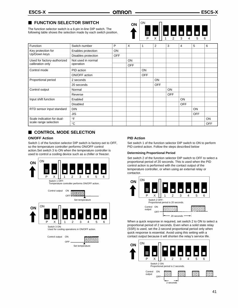
FUNCTION SELECTOR SWITCHThe function selector switch is a 6-pin in-line DIP switch. Thefollowing table shows the selection made by each switch position.
ON
1 65432P X
ON
Function Switch number P X 1 2 3 4 5 6
Key protection for Enables protection ONUp/Down keys Disables protection OFF
Used for factory-authorized Not used in normal ONcalibration only operation OFF
Control mode PID action ON
ON/OFF action OFF
Proportional period 2 seconds ON
20 seconds OFF
Control output Normal ON
Reverse OFF
Input shift function Enabled ON
Disabled OFF
RTD sensor input standard DIN ON
JIS OFF
Scale indication for dual- °F ONscale range selection °C OFF
CONTROL MODE SELECTIONON/OFF ActionSwitch 1 of the function selector DIP switch is factory-set to OFF,so the temperature controller performs ON/OFF controlaction.Set switch 3 to ON when the temperature controller isused to control a cooling device such as a chiller or freezer.
Control output ON
OFF
Set temperature
Switch 1 OFF:Temperature controller performs ON/OFF action.
ON
1 65432P X
ON
Control output ON
OFF
Set temperature
Switch 3 ON:Used for cooling operations in ON/OFF action.
ON
1 65432P X
ON
PID ActionSet switch 1 of the function selector DIP switch to ON to performPID control action. Follow the steps described below
Determining Proportional Period
Set switch 2 of the function selector DIP switch to OFF to select aproportional period of 20 seconds. This is used when the PIDcontrol action is performed with the contact output of thetemperature controller, or when using an external relay orcontactor.
Control ONoutput
OFF
20 seconds
Switch 2 OFF:Proportional period is 20 seconds.
ON
1 65432P X
ON
When a quick response in required, set switch 2 to ON to select aproportional period of 2 seconds. Even when a solid state relay(SSR) is used, set the 2-second proportional period only whenquick response is essential. Avoid using this setting with acontact output because it will shorten the relay’s service life.
Control ONoutput
OFF
2 seconds
Switch 2 ON:Proportional period is 2 seconds.
ON
1 65432P X
ON
E5CS-X E5CS-X
42
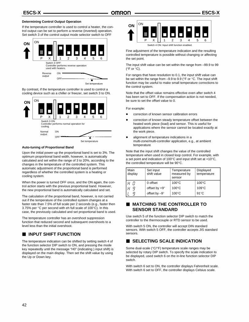
Determining Control Output Operation
If the temperature controller is used to control a heater, the con-trol output can be set to perform a reverse (inverted) operation.Set switch 3 of the control output mode selector switch to OFF
Reverse ONoutput
OFF
Set temperature
Switch 3 OFF:Controller performs reverse operationused with heaters.
ON
1 65432P X
ON
By contrast, if the temperature controller is used to control acooling device such as a chiller or freezer, set switch 3 to ON.
Normal ONoutput
OFF
Set temperature
Switch 3 ON:Controller performs normal operation forcooling.
ON
1 65432P X
ON
Auto-tuning of Proportional Band
Upon the initial power-up the proportional band is set to 3%. Theoptimum proportional band width, however, is automaticallycalculated and set within the range of 3 to 20%, according to thechanges in the temperature of the controlled system. Thisautomatic adjustment of the proportional band is performedregardless of whether the controlled system is a heating orcooling system.
When the power is turned OFF once, and the ON again, the con-trol action starts with the previous proportional band. However,the new proportional band is automatically calculated and set.
The calculation of the proportional band, however, is not carriedout if the temperature of the controlled system changes at afaster rate than 7.5% of full scale per 2 seconds (e.g., faster then3.75% per °C per second with eh full scale of 100°C). In thiscase, the previously calculated and set proportional band is used.
The temperature controller has an overshoot suppressionfunction that reduced second and subsequent overshoots to alevel less than the initial overshoot.
INPUT SHIFT FUNCTION
The temperature indication can be shifted by setting switch 4 ofthe function selector DIP switch to ON, and pressing the modekey repeatedly until the message “H0” (indicating ) input shift) isdisplayed on the main display. Then set the shift value by usingthe Up or Down key.
Switch 4 ON: Input shift function enabled.
ON
1 65432P X
ON
Fine adjustment of the temperature indication and the resultingcontrolled temperature is possible without changing or affectingthe set point.
The input shift value can be set within the range from –99.9 to 99(°F or °C).
For ranges that have resolution to 0.1, the input shift value canbe set within the range from –9.9 to 9.9 (°F or °C. The input shiftfunction may be useful to make small temperature corrections tothe control system.
Note that the offset value remains effective even after switch 4has been set to OFF. If the compensation action is not needed,be sure to set the offset value to 0.
For example:
correction of known sensor calibration errors
correction of known steady temperature offset between theheated work piece (load) and sensor. This is useful forapplications where the sensor cannot be located exactly atthe work piece.
alignment of temperature indications in amulti-zone/multi-controller application, e.g., at ambienttemperature
Note that the input shift changes the value of the controlledtemperature when used in closed loop control. For example, witha set point and indication of 100°C and input shift set at +10°C,the controlled temperature will be 90°C.
Main display
Set input shift value
Temperaturemeasured bysensor
Displayedtemperature
0 offset
offset by +9°offset by –9°
100°C100°C100°C
100°C109°C91°C
MATCHING THE CONTROLLER TO SENSOR STANDARD
Use switch 5 of the function selector DIP switch to match thecontroller to the thermocouple or RTD sensor to be used.
With switch 5 ON, the controller will accept DIN standardsensors. With switch 5 OFF, the controller accepts JIS standardsensors.
SELECTING SCALE INDICATION
Some dual-scale (°C/°F) temperature scale ranges may beselected by rotary DIP switch. To specify the scale indication tobe displayed, used switch 6 on the in-line function selector DIPswitch.
With switch 6 set to ON, the controller displays Fahrenheit scale.With switch 6 set to OFF, the controller displays Celsius scale.

E5CS-X E5CS-X
43
SELECTING A SCALE RANGEUse the rotary DIP switch to select the temperature scale range.The tables below show the switch setting number for each range.The temperature indication range is the set temperature range(full scale) ±10%, unless otherwise noted.
If the set temperature is shifted outside of changing the scalerange, the set temperature is displayed. It is then automatically
changed to the maximum or minimum value of the newly settemperature scale range.
If the alarm value is shifted outside the temperature scale rangeas a result of changing the scale range, it is automaticallychanged to the maximum value of the newly set scale range.
Thermocouple Input TypeThermocouple input models are factory-set to switch position 2for a temperature range of 0° to 400°, using a type Kthermocouple.
Switch setting 0 1 2 3 4 5 6 6 7 8 9
Temperature range 0 to 200 0 to 300 0 to 400 0 to 500 0 to 600 0 to 999 0 to 999 0 to 200 0 to 300 0 to 400 0 t0 500
Scale indication °C °C °C/°F °C/°F °C/°F °C/°F °F °C °C °C/°F °C/°FUnit of measure 1° C or F
Platinum RTD TypePlatinum RTD input models are factory-set to switch position 3for a temperature range of 0.0° to 99.9°.
Switch setting 0 1 2 3 4 5 6 7 8
Temperature range –50 to 50 0.0 to 50.0 –20 to 80 0.0 to 99.9 0 to 200 0 to 300 0 to 400 0 to 600 0 to 800
Scale indication °C °C °C °C/°F °C/°F °C °C/°F °F °FUnit of measure 1° C or F 0.1° C or F 1° C or F 0.1° C or F 1° C or F
Note: 1. Do not set the selector switch to position 9. This will cause error message “FFF” or “–––” to be displayed.2. When changing scale ranges where the unit of measure changes 1° to 0.1° or vice versa, the set temperature also changes to
reflect the unit of measure. For example, with a set temperature of 100°, a change from a scale range with 1° resolution to 0.1°makes the set temperature 10°; with a set temperature of 15°, a change in scale range resolution from 0.1° to 1° makes the settemperature 150°.
Thermistor Input TypeThermistor input models are factory-set to switch position 0 for atemperature range of –50° to 50C°.
Switch setting 0 1 2 3 4 5 6 7 8 9
Temp. range –50 to 50 0 to 100 50 to150
100 to200
150 to300
–50 to 100 0 to 200 100 to300
200 to400
300 to600
Scale indication °C °FUnit of measure 1° C or F
Note: 1. The temperature indication range for a setting scale of –50° to 50°C is –50° to 60°C. It is the full scale ±10% with the other set-ting scale ranges.
2. With a temperature range, such as 50° to 150°C, exceeds the factory-set range, the indication unit is automatically adjusted tothe minimum value. The set temperature is displayed upon power application.

E5CS-X E5CS-X
44
SELECTING ALARM MODESSelect one of the eight alarm modes by using the rotary DIPswitch located next to the rotary DIP switch for temperature scalerange selection. The following table shows alarm functions. Theselector switch is factory-set to position 2, upper-limit alarm.
Switch setting Mode Alarm output Notes
0, 9 No alarm OFF When the alarm mode selector switch is 0 or 9,neither the alarm value is displayed nor the ALindicator lights even when the return key is pressed.
1 Upper- and lower-limit alarms Alarm value setting range X may be 0 to full scale.
If the alarm value is shifted outside the temperature
2 Upper-limit alarm
If the alarm value is shifted outside the temperaturescale range as a result of changing the scale range, itis automatically changed to the maximum value of thenewly set scale range.
3 Lower-limit alarm
4 Upper- and lower-limit range alarm
5 Upper- and lower-limit alarms withstandby sequence
6 Upper-limit alarm with standbysequence
7 Lower-limit alarm with standbysequence
8 Absolute-value alarm Alarm value setting range Y must be within thetemperature scale range.
Standby SequenceAlarm functions with standby sequence suppress nuisancealarms when the controller is first powered up. As shown in thetemperature charts at right, the alarm output is suppressed untilthe temperature exceeds the alarm band or alarm limit one time.
When temperature rises from the set temperature
Upper-limit alarm
Set temperature
Lower-limit alarm
Alarm output ON
OFF
When temperature falls below the set temperature
Upper-limit alarm
Set temperature
Lower-limit alarm
Alarm output ON
OFF
SETTING KEY PROTECTIONProtect against unauthorized changes in temperature values bydisabling the operation of Up and Down keys. Set functionselector DIP switch “P” to ON. To enable changes from the frontpanel, simultaneously press the hidden write protection key(lower left corner) with the Up and Down keys. If the internalprotection switch is set to OFF, changes can be made simply bypressing the Up and Down keys.
ON
1 65432P X
ON

E5CS-X E5CS-X
45
WHEN ALL FUNCTIONS HAVE BEEN SELECTEDTo Set TemperaturePress the return key until the SP indicator lights. Then set thedesired temperature value by using the Up and Down keys.
To Set Alarm ValuePress the return key until the AL indicator lights. Then set thedesired alarm value in units of °F or °C. If the present tempera-ture exceeds the set alarm value, the alarm output will be issued.
Neither the set alarm value is displayed nor the AL indicatorlights with the integral alarm mode setting switch set to 0 or 9. Besure to check the alarm mode setting switch, located inside thehousing, for proper setting.
In Case of Sensor FailureThe error message “FFF” or “–––” will appear on the main displayif the temperature sensor short-circuits or breaks.
PrecautionsThe E5CS-X temperature controller has self-diagnostic functions that display the following error messages to simplify troubleshooting.
Message Cause Control output
(1) Temperature has risen beyond temperature scale range(2) Thermistor has been short-circuited
OFF during heating (reverse) operationON during cooling (normal) operation
(1) Temperature has fallen below temperature scale range(2) Thermistor has broken
ON during heating (reverse) operationOFF during cooling (normal) operation
(blinks)* (1) Failure has occurred in thermocouple or platinum RTD(2) Temperature has risen much beyond scale range
OFF
(blinks)* (1) Failure has occurred in platinum RTD(2) Polarities (positive and negative) of thermocouple are reversed(3) Temperature has fallen much below scale range
OFF
or * (1) Memory failure (E11) display(2) Analog-to-digital converter failure (E33) display
Temperature controller must be repaired if recovery is not made by turning power off once and on again.
Both control outputs and the alarm outputare OFF
Note: *Key operations are disabled.When the alarm outputs are used, an alarm output occurs when the “FFF” and “–––” messages appear in the display. These dis-plays indicate when the temperature has risen beyond or fallen below the temperature scale range.
SENSOR FAILURE INDICATIONCondition Display Control output
Thermocouple sensor
Break in sensor blinks OFF
Short-circuit Ambient temperature OFF
Platinum RTD sensor
Break in sensor blinks OFF
blinks OFF
Disconnection of two or three wires blinks OFF
Short-circuit blinks OFF
Thermistor sensor
Break in sensor ON during heating (reverse) actionOFF during cooling (normal) action
Short-circuit ON during heating (reverse) actionOFF during cooling (normal) action
Note: The resistance of the platinum RTD is 100 Ω at 0°C and increases to 140 Ω at 100°C.

E5CS-X E5CS-X
Installation MOUNTINGAll E5CS-X models conform to DIN 43700 standard. Recom-mended panel thickness is 1 to 4 mm (0.04 to 0.16 in).
Insert the temperature controller, back end first, into the panelcutout. Mount the adapter (Y92F-30) supplied with each unit bypushing it forward from the back of the temperature controller.Push the adapter as close as possible to the front panel of thetemperature controller to eliminate the gap between them. Then,secure the adapter with screws as shown.
RemovalLoosen the screws on the adapter and push the hook open toremove the adapter.
Hook
Screw
CONNECTIONS
Connection ExamplesUse M3.5 solderless terminals with the temperature controller’sM3.5 self-rising pressure plate screws.
For solder-dipped leads, strip the lead wire 6 to 12 mm (0.24 to0.47 in) and carefully insert the wire tip. Do not tighten the termi-nal screw with excessive force.
7.5(0.29)
7.3 (0.29)max.
19(0.75) 6 to 12
(0.24 to 0.47)
Precautions ENVIRONMENTDo not install the temperature controller in a location where thereis a lot of dust or corrosive gases. Also avoid a location wherethe temperature controller is subjected to heavy vibration, shock,splashes of water or oil, and high temperatures.Separate the temperature controller from equipment thatgenerates strong, high-frequency electrical noise such as weldingequipment.
Sensor Input ConnectionsThe lead wires connecting the platinum RTD to the temperaturecontroller must be separated from the power lines an the loadlines, wherever possible, to prevent them from being inducted byelectrical noise.
Use the specified compensating conductors for the thermocoupleinput type temperature controllers.
Use lead wires having a small resistance for the platinum RTDtype temperature controllers.
Sequence Circuit
Several seconds are required until the relay is turned ON afterthe power has been applied to the temperature controller. Besure to take this time lag into consideration when designing asequence circuit which incorporates this temperature controller.
RECALIBRATION
The E5CS-X temperature controller can be recalibrated by afactory-authorized repair service. Contact Omron for the locationnear you.
Unauthorized recalibration of the controller will void the warrantyand may lead to erraticoperation.
Cat. No. GCTC13 8/00 Specifications subject to change without notice. Printed in U.S.A.
OMRON ELECTRONICS, INC.One East Commerce DriveSchaumburg, IL 60173
1-800-55-OMRON
OMRON CANADA, INC.885 Milner AvenueScarborough, Ontario M1B 5V8
416-286-6465


![[KGIT_EWD]class03 0322](https://static.fdocuments.net/doc/165x107/555e0ca5d8b42a99188b4be1/kgitewdclass03-0322.jpg)

