OPERATOR'S MANUAL TCR-MBA-50 AND TCR-MBA · PDF fileOPERATOR'S MANUAL TCR-MBA-50 AND...
35
OPERATOR'S MANUAL TCR-MBA-50 AND TCR-MBA-50 WB MULTI-BAND RF AMPLIFIERS DOCUMENT # 90400-01141 Tricom Research, Inc. http://www.tricomresearch.com 17981 Sky Park Circle, Suite M, Irvine, CA 92614 Ph: (949) 250-6024 fax: (949) 250-6023
Transcript of OPERATOR'S MANUAL TCR-MBA-50 AND TCR-MBA · PDF fileOPERATOR'S MANUAL TCR-MBA-50 AND...

OPERATOR'S MANUAL
TCR-MBA-50 AND TCR-MBA-50 WB
MULTI-BAND RF AMPLIFIERS
DOCUMENT # 90400-01141 Tricom Research, Inc. http://www.tricomresearch.com
17981 Sky Park Circle, Suite M, Irvine, CA 92614
Ph: (949) 250-6024 fax: (949) 250-6023

TCR-MBA-50 AND TCR-MBA-50 WB OPERATOR’S MANUAL
i
Revision History - Document 90400-01141
Revision Description Date
P1 Preliminary Release 23 Feb 2012
P2 Added details of high temperature failsafe operation 28 Feb 2012
P3 Updated current draw specifications, added WB
option 11000-00744 information and added Appendix
B for Bias Tee installation instructions
25 Apr 2012
A Official Release 24 Oct 2012
B Changed Figure 3-7, added auxiliary connector pin 12
description
4 Dec 2012
C Added TCR-MBA-50 information 15 Mar 2013
D Changed references to LVL indicator and RF input
power
5 Mar 2014
Note: The latest version of this manual can be downloaded from our website at
http://www.tricomresearch.com/downloads.html.

TCR-MBA-50 AND TCR-MBA-50 WB OPERATOR’S MANUAL
ii
TABLE OF CONTENTS
1.0 INTRODUCTION 1.1 General Information .......................................................................................1
1.2 Abbreviations and Glossary ...........................................................................2
1.3 Equipment Description ..................................................................................3-6
1.4 Features ..........................................................................................................7
1.5 TCR-MBA-50 WB System ............................................................................7
1.5.1 Amplifier Components...................................................................................7
1.5.2 Power Cable ...................................................................................................8
1.6 Specifications .................................................................................................8-9
2.0 OPERATION 2.1 General Information .......................................................................................11
2.2 Controls, Indicators, and Connectors .............................................................11-13
2.3 Operation........................................................................................................13
2.3.1 General Information .......................................................................................13
2.3.2 Equipment Set-up...........................................................................................13
2.3.3 Operating Procedures .....................................................................................13
2.3.3.1 Push Button Switch Operation .......................................................................13-15
2.3.3.2 LNA Operation Precautions ...........................................................................15
2.3.3.3 Remote Control Operation .............................................................................15
2.3.3.4 Out of Band Operation ...................................................................................15
2.3.3.5 Bypass Operation ...........................................................................................15
2.3.3.6 Troubleshooting .............................................................................................15-16
3.0 INSTALLATION 3.1 General Information .......................................................................................17
3.2 Preparation for Use ........................................................................................17
3.3 Mounting Provisions ......................................................................................17
3.4 DC Input Power .............................................................................................20
3.5 RF Interconnections .......................................................................................20
3.6 Remote Control Interface ...............................................................................22
3.7 Remote Control Command Set ......................................................................24

TCR-MBA-50 AND TCR-MBA-50 WB OPERATOR’S MANUAL
iii
LIST OF TABLES
Table 1-1 Nominal Performance Specifications ......................................................8-9
Table 1-2 Interconnect Characteristics .....................................................................10
Table 2-1 Mode Indicators .......................................................................................12
Table 2-2 Power Output Level Indicators ................................................................12
Table 2-3 Front Panel Controls ................................................................................13
Table 2-4 I/O Connectors .........................................................................................13
Table 2-5 Troubleshooting Guide ............................................................................16
Table 3-1 DC Input Power Connector Pinout ..........................................................20
Table 3-2 DC Input Power Control Pin Functions ...................................................20
Table 3-3 Auxiliary Connector Pinout .....................................................................22
Table 3-4 Remote Control Command Set ................................................................24
Table B-1 Bias Tee 3 Troubleshooting Guide ..........................................................30
LIST OF FIGURES
Figure 1-1 TCR-MBA-50 WB...................................................................................1
Figure 1-1 TCR-MBA-50 ..........................................................................................1
Figure 2-1 Amplifier Controls & Indicators ..............................................................11
Figure 2-2 Amplifier Connections .............................................................................11
Figure 3-1 TCR-MBA-50 WB Outline Drawing (1 of 2)..........................................18
Figure 3-2 TCR-MBA-50 WB Outline Drawing (2 of 2)..........................................19
Figure 3-3 Amplifier DC Input Connector ................................................................20
Figure 3-4 Commercial Vehicle DC Power Cable ....................................................21
Figure 3-5 Military Vehicle DC Power Cable ...........................................................21
Figure 3-6 Military Battery DC Power Cable............................................................21
Figure 3-7 Auxiliary Connector Pinout .....................................................................22
Figure 3-8 USB Remote Control Cable .....................................................................23
Figure 3-9 RS-232 Remote Control Cable ................................................................23
Figure B-1 Military Vehicle DC Power Cable ...........................................................29
Figure B-2 Bias Tee 3 (PA) Installation .....................................................................29
Figure B-3 Bias Tee 3 Interconnect Diagram ............................................................31
Appendix A MS Windows Serial Comm Port Reassignment ......................................25
Appendix B Bias Tee 3 Installation Instructions..........................................................28
Note: The information contained herein is for reference only and does not constitute a warranty
of performance.

1
1.0 INTRODUCTION
1.1 GENERAL INFORMATION
This manual provides operating instructions for the TCR-MBA-50 and TCR-MBA-50
WB Multiband Amplifiers shown in Figure 1-1 and Figure 1-2. Both amplifiers are
physically identical except that the TCR-MBA-50 does not have the BNC connector for
the WB antenna port and the WB function is disabled (refer to Figure 1-2). The
TCR-MBA-50 and TCR-MBA-50 WB amplifiers are designed to provide transmit and
receive gain for the following modes of operation:
Multiband line of sight (LOS FM and AM) 30-512 MHz communications
SINCGARS frequency hopping 30-88 MHz operation
HAVEQUICK frequency hopping 225-400 MHz
UHF Tactical SATCOM (242-268 MHz receive and 292-318 MHz transmit)
frequencies with Low Noise Amplifier (LNA) and Cosite suppression
SRW and ANW2 Wideband Networking Waveforms in the 225-450 MHz band
(available only on the TCR-MBA-50 WB)
Note: TCR-MBA-50 Power Amplifiers can be upgraded to TCR-MBA-50 WB by
purchasing the wideband upgrade kit part number 11000-00744. Wideband upgrades can
only be installed at the factory.
Figure 1-1. TCR-MBA-50 WB
Figure 1-2. TCR-MBA-50
2
1.2 ABBREVIATIONS AND GLOSSARY
AGC Automatic gain control
ALC Automatic level control
AM Amplitude modulation
ANT Antenna
ANW2 Advanced Networking Wideband Waveform
BPS Bits per second
CT Cipher text
CW Continuous wave
COMSEC Communications security
dB Decibel
dBm Decibel referenced to 1 milliwatt (0 dBm = 1 mW)
FM Frequency modulation
Hz Hertz
IW Integrated Waveform
JITC Joint Interoperability Test Center (DISA)
kHz Kilohertz
LED Light emitting diode
LNA Low Noise Amplifier
LOS Line of sight
MHz Megahertz
mW Milliwatt
PT Plain text
PTT Push to Talk
RCV Receive
SATCOM Satellite Communications
SF Single Frequency
SRW Soldier Radio Waveform
UHF Ultra-high frequency
VDC Volts, direct current
VSWR Voltage standing wave ratio
W Watt
WB Wideband
XMT Transmit

3
1.3 EQUIPMENT DESCRIPTION
The TCR-MBA-50 and TCR-MBA-50 WB are bi-directional half duplex RF Power Amplifiers
providing transmit amplification for 30-512 MHz FM/AM Line-of Sight (LOS), 30-88 MHz FM
SINCGARS Frequency Hopping, 225-400 MHz AM HAVE QUICK Frequency Hopping, 292-
318 MHz (transmit band) UHF Tactical SATCOM and 225-450 MHz ANW2 and SRW
Wideband Networking bands (wideband networking applies only to TCR-MBA-50 WB). A low
noise amplifier provides receive gain for the 242-268MHz UHF Tactical SATCOM receive
band. It is suitable for vehicular, airborne, man-portable or fixed-station applications and is
compatible with most military and commercial radios operating in the 30MHz - 512MHz
frequency spectrum. The operation of the amplifier can be controlled locally via front panel
switches or from USB and RS-232 interfaces for remote control operation. There is also a Bias
Tee 3 available (Tricom Research Part Number 11000-00735) for remote operation of the
amplifier. The amplifier has a DC input connection, a radio port and three mode specific antenna
ports. The LOS mode port is for AM and FM frequency hopping (non-wideband) and multiband
Line of Site operation from 30-512MHz. The SATCOM mode port is band limited to UHF
TACSAT Frequencies for 5 and 25 KHz channels, DAMA and IW communications. The WB
mode port is used for Wideband Networking and Wideband Frequency Hopping Networking
modes (applicable only to TCR-MBA-50 WB).
1.3.1 USER SET MODES.
The following modes are available to the user via the front panel push buttons or with the remote
interface:
LOS MODE BUTTON LOS FM
FREQUENCY HOP FM
LOS AM
FREQUENCY HOP AM
*ANW2/SRW WB (Wideband Networking Waveforms)
*ANW2//SRW WB HOP (Wideband Networking Waveforms)
SAT MODE BUTTON
SATCOM (LNA ON)
SATCOM (LNA OFF)
*Applicable only to TCR-MBA-50 WB.
The mode button selection determines which output antenna port is active. If the LOS button is
pressed while the amplifier is in a SATCOM mode, the amplifier will return to the last used LOS
mode. The next LOS button press will sequence to the next available LOS mode. The same is
true for the SAT button when pressed while in LOS mode. This way, the user may toggle
between set SATCOM and LOS modes by alternately pressing the two mode control buttons,
without having to cycle through the entire menu structure. Note that the WB modes are accessed
via the LOS mode button.

4
1.3.2 TRANSMIT POWER LEVELS.
The PA has two available RF output power levels for LOS (25 and 50 W), one RF output power
level for ANW2 and SRW WB modes (25 W available only on TCR-MBA-50 WB), and five
available RF output power levels for SATCOM (10, 15, 25, 35 and 50 W, in order to comply
with MIL-STD-188-181b 2 dB RF output adjustments). These are the maximum available
power levels only, as other restrictions, including input voltage, source current limitations, and
input power levels may cause the PA to limit output power and also limit the available power
level selections. The nominal transmit power level is determined by various factors, the DC
input mode (as listed in Table 1-1), the TCR-MBA-50 power button on the amplifier front panel,
and by the optional remote control interface. The DC power source and source specific DC
cable (DC cables are wired differently depending on the end user’s DC source), will also
determine the maximum allowable current draw, which subsequently determines the maximum
allowable output power. The PWR button or the remote interface will then be able to select from
the allowable output power levels for each DC cable defined mode:
Military Battery Mode (12.5 VDC nominal):
20 Watts in LOS and WB modes, 10, 15 or 25 Watts in SATCOM and maximum
current draw not to exceed 4.75 Amps.
Commercial Vehicle Mode (13.8 VDC nominal):
25 Watts in LOS and WB modes; 10, 15 or 25 Watts in SATCOM and maximum
current draw not to exceed 5.5 Amps.
Military Vehicle Mode (28 VDC nominal):
25 or 50 Watts in LOS; 25 Watts in WB and 10, 15, 25, 35 or 50 Watts in SATCOM
and maximum current draw not to exceed 6.8 Amps.
1.3.3 POWER ON, INITITALIZATION AND MODE CHANGES.
A single pushbutton switch provides power ON/OFF control, RF output power level control and
LED intensity control. Pressing the button momentarily (<2 seconds) will cycle through the
different power levels as described in paragraph 1.3.2. Holding the button down longer than 2
seconds will dim the LEDs in 4 steps at 1 second intervals before the PA shuts down; releasing
the PWR button before the PA shuts down will set the LED intensity at one of 4 levels (high,
medium, medium low, low). The LOS and SATCOM mode buttons will cycle through the
operational modes described in Section 1.3.1. Non-volatile memory will remember the last
operational state and the PA will return to that state when power is restored.
If PIN E (auto-start) on the DC input power connector is unconnected (open) and the DC supply
is disconnected and re-connected the PA will remain in the OFF state until the PWR button is
used to turn the PA back on. After turning on, the PA will return to the last operating mode. If

5
power is shut off using the PWR button and the DC supply is then disconnected and re-
connected, the PA will likewise remain in the OFF state.
If PIN E on the DC input power connector is tied to GROUND (auto start configuration) and the
DC power is disconnected and re-connected, the amplifier will automatically power ON into the
last operational mode. This feature is useful in installations where the front panel is not
accessible and DC power is controlled remotely.
1.3.4 MODE OF OPERATION INDICATORS.
There are ten front panel LED's used to indicate the different modes of operation and power
amplifier operational status. Table 2-1 describes the LED indicators for the different modes of
operation and Table 2-2 describes the different power levels that are available for each mode of
operation.
1.3.4.1 SATCOM MODE INDICATOR (SAT).
The SAT LED will illuminate whenever one of two SATCOM modes is selected (SAT LNA
ON, SAT LNA OFF).
1.3.4.2 LOW NOISE AMPLIFIER MODE INDICATOR (LNA).
The LNA LED will illuminate whenever the SATCOM/LNA ON mode is selected (SAT LNA
ON). When in SAT mode, pressing the SAT button will toggle the LNA on and off.
1.3.4.3 WIDEBAND MODE INDICATOR (WB).
The WB LED will illuminate whenever one of two WB modes is selected (WB Single Frequency
and WB Frequency Hopping). Scrolling through the LOS menu (pressing the LOS button) will
cycle the user to the WB modes. These modes are only available on the TCR-MBA-50 WB.
1.3.4.4 LINE OF SIGHT MODE INDICATOR (LOS).
The LOS LED will illuminate whenever one of four LOS modes is selected (LOS FM, LOS FM
Frequency Hopping, LOS AM, LOS AM Frequency Hopping).

6
1.3.4.5 FREQUENCY HOPPING MODE INDICATOR (FH).
The FH LED will illuminate whenever one of three frequency hopping modes is selected (LOS
FM Frequency Hopping, LOS AM Frequency Hopping and WB Frequency Hopping).
1.3.4.6 AMPLITUDE MODULATION MODE INDICATOR (AM).
The AM LED will illuminate whenever one of two amplitude modulation modes is selected
(LOS AM, LOS AM Frequency Hopping).
1.3.4.7 RF INPUT LEVEL UNDER/OVER DRIVE (LVL).
This feature is not currently active but will be implemented in future upgrades.
1.3.4.8 TX STATUS INDICATOR (TX).
The TX LED will illuminate during a good transmit condition. Depending on the duty cycle of
some data transmission waveforms such as DAMA, ANW2 and SRW, the TX LED may flicker.
This is due to the fast switching time between transmit and receive and DOES NOT indicate a
system malfunction.
1.3.4.9 FAULT STATUS INDICATORS (FLT).
The FLT LED will illuminate to indicate a fault condition, such as attempting to transmit at a
frequency that is not valid in the selected mode or over temperature conditions.
1.3.4.10 REMOTE OPERATION STATUS INDICATOR (RMT).
The REMOTE LED will illuminate when the PA has received a REMOTE ON command from
an external terminal and will stay on until the REMOTE OFF command has been received.
Note that the front panel LOS and SAT buttons are ignored during remote operation.
1.3.5 REMOTE CONTROL INTERFACE.
USB (+5, GND, D+ and D-) and RS-232 interfaces (GND, TXD and RXD only) will provide
remote control of the amplifier’s modes of operation and power levels. When a terminal has
been connected to the remote interface and the proper escape sequence has been sent by the
terminal (refer to sections 3.5 and 3.6 for remote control operation) the PA will start
communications with the terminal and will illuminate the RMT LED on the front panel. At this
point the TCR-MBA-50 (both versions) front panel buttons will become inactive, except to
power the amplifier off. The PA will NOT detect the removal of the remote interface connection
and will remain in remote mode until the power is cycled OFF, if the remote control cable is
unexpectedly removed.

7
1.4 FEATURES
The TCR-MBA-50 (both versions) has the following features:
DAMA, DAMA IW and Special Communications modes of operation compatible
ANW2 and SRW Wideband Networking Waveforms compatible in the 225-450 MHz
band (available only on TCR-MBA-50 WB)
Coverage from 30 to 512 MHz, including SINCGARS FM and HAVEQUICK AM
Frequency Hopping compatibility
Connections for SATCOM, LOS and WB antennas
Pre-amplification of received RF signals from antennas connected to the SATCOM
port
Power amplification of transmit signals to 25 or 50 Watts in LOS; 10, 15, 25, 35 and
50 Watts in SATCOM, and 25 Watts in the WB modes
Transmit and receive band filtering to suppress interference from
co-located radios and amplifiers in SATCOM and WB modes
Amplifier front panel indication of system status
1.5 TCR-MBA-50 (BOTH VERSIONS) SYSTEM
The TCR-MBA-50 WB is pictured in Figure 1-1 and the TCR-MBA-50 is pictured in
Figure 1-2.
1.5.1 Amplifier Components
The Amplifier consists of several printed circuit board assemblies, a filtering and switching
network, and RF connectors housed in a water resistant aluminum housing. With normal care
and maintenance, the assembly is highly resistant to corrosion from the elements. The RF
connections to the RF radio input, SATCOM antenna, LOS antenna, and WB antenna are BNC
female (WB antenna BNC connector is not installed on TCR-MBA-50). Power to the amplifier is
applied via a cable connected to a six pin circular DC input connector.

8
1.5.2 Power Cable
A multi-conductor cable connects the amplifier with an external DC power source. A wiring
diagram for the cable is shown in Section 3 of this manual. The DC power cable used with the
legacy TCR-MBA-25 power amplifier may be used to power the TCR-MBA-50 (both versions);
however, the connection for the Auto Power ON (pin E grounded on the power cable) may have
to be added (refer to paragraph 2.3.3.1).
1.6 Specifications
The operating parameters, physical characteristics, and environmental specifications are shown
in the following tables.
Table 1-1. Nominal Performance Specifications
TRANSMIT SECTION
SATCOM OPERATION
Frequency Range 292-318 MHz
Switching Speed JITC DAMA and IW compatible
Modulation FM or Phase modulation
RF Power Input 5 Watts (2-10 Watts typical)
RF Power Output BA-5590 (12.7 VDC 4.75 A max): 10, 15, 20 Watts
BB-2590 (15 VDC 4.75 A max): 10, 15, 25 Watts
Commercial Vehicle (13.5 VDC 5.5 A max): 10, 15, 25 Watts
Military Vehicle (28 VDC 6.8 A max): 10, 15, 25, 35, 50 Watts
Filtering Cosite suppression
LOS OPERATION
Frequency Range 30-512 MHz with Automatic Frequency Detection
Modulation AM, FM, AM/FM Frequency Hopping
Band Selection Fully automatic
RF Power Input 5 Watts Avg/Peak (2-10 Watts typical)
RF Power Output BA-5590 (12.7 VDC 4.75 A max): 20 Watts Avg/Peak
BB-2590 (15 VDC 4.75 A max): 25 Watts Avg/Peak
Commercial Vehicle (13.5 VDC 5.5 A max): 25 W Avg/Peak
Military Vehicle (28 VDC 6.8 A max): 25, 50 W Avg/Peak
WB OPERATION (TCR-MBA-50 WB only)
Frequency Range 225-450 MHz with Automatic Frequency Detection
Band Selection Fully automatic
RF Power Input 5 Watts Avg/Peak (2-10 Watts typical)
RF Power Output BA-5590 (12.7 VDC 4.5 A max): 20 Watts Peak
BB-2590 (15 VDC 4.5 A max): 25 Watts Peak
Commercial Vehicle (13.5 VDC 5.5 A max): 25 W Peak
Military Vehicle (28 VDC 6.0 A max): 25 W Avg

9
Table 1-1. Nominal Performance Specifications (continued)
RECEIVE SECTION
SATCOM OPERATION
Frequency Range 242-268 MHz
Noise Figure 3.75 dB typical
Receive Gain 10 dB typical
LOS OPERATION
Frequency Range 30-512 MHz
Insertion Loss <2.5 dB
WB OPERATION (TCR-MBA-50 WB only)
Frequency Range 225-450 MHz
Insertion Loss <3.5 dB
ADDITIONAL SPECIFICATIONS
Radio Connector BNC female
LOS Antenna Connector BNC female
SAT Antenna Connector BNC female
WB Antenna Connector BNC female (not installed on TCR-MBA-50)
DC Connector MS3112E10-6P
Auxiliary Connector Optional RS-232 Cable (PN 77500-00390),
Optional USB Cable (PN 77500-00391)
High Temperature High Temperature Indication/Fold back
DC Off Routes Radio signal to LOS port
Operating Temperature -30 to +60 C
Cooling Natural Convection
Dimensions 2” H x 3.5” W x 8.15” D
Weight 3.4 lbs
The information in section 1.6 is included for reference only and does not constitute a warranty
of performance.

10
Table 1-2. Interconnect Characteristics
Connection Signal/Pin Connector Function
DC IN DC power input
PIN A
PIN B
PIN C
PIN D
PIN E
PIN F
MS3112E10-6P
(mating connector for cable use is
MS3116F10-6S)
12-32 VDC Input
GND
Commercial Vehicle Select (12 V)
Military Vehicle Select (28 V)
Auto Power On Select
Reserved
RADIO RF from radio Type BNC female
LOS
SAT
*WB
To LOS Antenna
To SATCOM Antenna
To WB Antenna
Type BNC female
Type BNC female
Type BNC female
*Available only on TCR-MBA-50 WB.
11
2.0 OPERATION
2.1 General Information
This section provides information for operating the TCR-MBA-50 (both versions).
WARNING
Electromagnetic radiation from the antenna can damage eyes and other body tissue when
the system is transmitting. DO NOT stand directly in front of the antenna or in close
proximity to the sides or back of the antenna when transmitting.
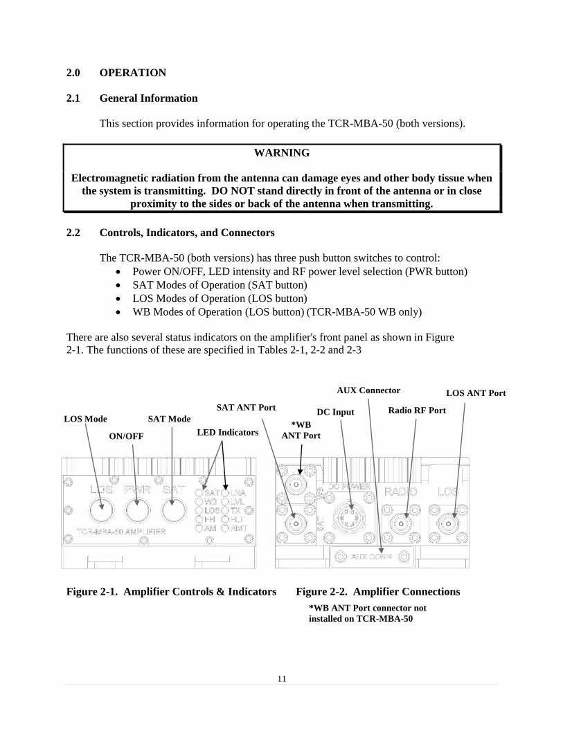
2.2 Controls, Indicators, and Connectors
The TCR-MBA-50 (both versions) has three push button switches to control:
Power ON/OFF, LED intensity and RF power level selection (PWR button)
SAT Modes of Operation (SAT button)
LOS Modes of Operation (LOS button)
WB Modes of Operation (LOS button) (TCR-MBA-50 WB only)
There are also several status indicators on the amplifier's front panel as shown in Figure
2-1. The functions of these are specified in Tables 2-1, 2-2 and 2-3
Figure 2-1. Amplifier Controls & Indicators Figure 2-2. Amplifier Connections
*WB ANT Port connector not
installed on TCR-MBA-50
Radio RF Port DC Input
LOS ANT Port
SAT ANT Port
LOS Mode
ON/OFF
SAT Mode
LED Indicators
AUX Connector
*WB
ANT Port

12
Table 2-1. Mode Indicators
Table 2-2. Power Output Level Indicators
*Applies only to TCR-MBA-50 WB.
Note 1: The 35 and 50 Watt power levels are only available in military vehicle mode (pin D
grounded on the DC input power connector with a 28 VDC source).
The modes of operation and power levels will cycle in the order indicated in Table 2-1 and Table
2-2 from top to bottom. The settings will cycle through in a loop, to select a different mode or
power level, the mode or power switch must be pressed repeatedly until the next desired mode of
operation or power level is selected. The power levels are selected by momentarily pressing the
PWR button (refer to section 2.3.3). The LEDs for power indication will turn on and remain on
as long as the RF output power is being adjusted and will revert back to their normal function 2
seconds after the desired power level is selected. The power level indication will also
momentarily illuminate when the modes are changed and at initial turn on of the amplifier.
MODE OF OPERATION LED
LOS MODES SAT LNA WB LOS FH AM
LOS FM ON
LOS FREQUENCY HOP FM (SINCGARS) ON ON
LOS AM ON ON
LOS FREQUENCY HOP AM (HAVE QUICK) ON ON ON
*LOS WB ANW2/SRW ON
*LOS FREQUENCY HOP WB ANW2/SRW ON ON
SATCOM MODES
SATCOM LNA ON ON ON
SATCOM LNA OFF ON
MODE OF OPERATION LED
10 W 15 W 25 W 35W 50W
LOS MODES RMT FLT TX LVL LNA
LOS FM/AM SF/FREQUENCY HOP 25 Watts ON ON ON
LOS FM/AM SF/FREQUENCY HOP 50 Watts (Note 1) ON ON ON ON ON
WB MODES
*LOS WB SF/FREQUENCY HOP 25 Watts ON ON ON
SATCOM MODES
SATCOM LNA ON/OFF 10 Watts ON
SATCOM LNA ON/OFF 15 Watts ON ON
SATCOM LNA ON/OFF 25 Watts ON ON ON
SATCOM LNA ON/OFF 35 Watts (Note 1) ON ON ON ON
SATCOM LNA ON/OFF 50 Watts (Note 1) ON ON ON ON ON

13
Table 2-3. Front Panel Controls
CONTROLS TYPE FUNCTION
ON/OFF Push Button Switch Selects ON or OFF (Bypass) mode of
operation, RF output power level (button press
<2 seconds), LED intensity (button press >2
seconds but <6 seconds). After 6 seconds the
PA shuts down. When in Bypass, the amplifier
makes a connection from RADIO input to the
LOS connector output.
LOS MODE Push Button Switch Selects the LOS and WB modes of operation
(refer to Table 2-1)
SAT MODE Push Button Switch Selects the SATCOM modes of operation
(refer to Table 2-1)
Table 2-4 I/O Connectors
CONNECTIONS TYPE FUNCTION
SATCOM Antenna BNC Type RF connector Used to attach SATCOM Antenna
RADIO BNC Type RF Connector Used to attach to Transceiver
LOS Antenna BNC Type RF Connector Used to attach Line of Sight Antenna
WB Antenna BNC Type RF Connector Used to attach Wideband Antenna
NOT INSTALLED ON TCR-MBA-50
DC Power input connection Circular Mil connector Used to apply DC power input to amplifier
Auxiliary Port Custom 12 pin flat contact
connector
Used for remote control and other special
functions
2.3 Operation
2.3.1 General Information
The TCR-MBA-50 (both versions) can be used for operation once it has been installed as
described in Section 3.
2.3.2 Equipment Set-up
Refer to Paragraph 2.2 for the locations and functional description of the controls and indicators.
Make sure that the TCR-MBA-50 (both versions) has been installed according to the instructions
provided in Section 3.
2.3.3 Operating Procedures
2.3.3.1 Push Button Switch Operation
In normal operation, the TCR-MBA-50 (both versions) provides transmit power amplification
for radios operating in the 30-512 MHz VHF and UHF bands. The mode switch provides
selection for either the SATCOM, LOS or WB modes and the PWR button selects the power
levels (Refer to Table 2-1 and Table 2-2). RF output to the SATCOM, LOS or WB antenna ports
is automatically selected and determined by the mode selected.

14
PWR button - ON/OFF- To turn the amplifier ON, press and hold the PWR button for more
than 1-2 seconds. The PA will turn ON and display the current power level for approximately 3
seconds. The PWR button cycles the TCR-MBA-50 (both versions) from power ON to power
OFF (LOS Bypass mode). To switch the power amplifier back to the Power OFF (Bypass mode)
press and hold the PWR button for more than 6 seconds (the LEDs will dim as the PWR button
is pressed and held down). When in the Power OFF Bypass mode the RF is automatically routed
to the LOS antenna port directly from the transceiver. The Amplifier remembers the last state it
was in when powered down.
If the auto power ON mode is selected by grounding pin E on the DC input power connector, the
power to the PA can be turned ON or OFF by turning on or off the DC supply. If the auto power
ON mode is not enabled, removing the DC power will turn the power amplifier OFF but the
PWR button must be used to turn the power amplifier back ON when external DC power is
restored.
PWR button – RF Output Power Level Select - To select the desired RF output power level
press the PWR button momentarily (< 2 seconds). The power will increase to the next power
level from the previously set value on the first button press and will continue to the next
allowable level (mode and DC voltage level dependent refer to Table 2-2) for each subsequent
PWR button press until the desired level is reached. The LEDs for power level indication will
revert back to their normal function approximately 2 seconds after the last button press. Note
that in some modes only a single power level is available so the power level display will not
change.
PWR button – LED Intensity Level Select- Press and hold the PWR button for more than 2
seconds to select one of four available LED intensity levels (high, medium, medium low, low).
As the button is held down for more than 2 seconds, the LED intensity will decrease to the next
level; however, if the button is held down for more than 6 seconds the PA will shut down. To
select an LED intensity level, simply release the PWR button when the desired brightness is
displayed. If the external DC power is interrupted, the LED brightness will default to HIGH
when power is restored and the PA is turned back on using the PWR button; however, shutting
down and turning the PA back on using the PWR button will remember the last LED intensity
level.
LOS Mode- Press the LOS mode button repeatedly to select the desired LOS mode (refer to
Table 2-1) or WB mode. When any of the LOS modes are selected, RF is routed to the LOS RF
port. Selecting a WB mode routes the RF to the WB connector (applies only to TCR-MBA-50
WB or TCR-MBA-50 with option 11000-00744 installed). Frequency hopping can be selected
by cycling through the different modes of operation using the LOS mode button as described in
Table 2-1.
SATCOM Mode- Press the SAT mode button to select the SATCOM mode (refer to Table 2-1)
and to toggle the LNA on and off as described in Table 2-1. The SATCOM mode routes the RF
to the SAT port. The LNA provides an average 10dB receive gain for use in disadvantaged

15
installations where either Omni-directional SATCOM antennas are used or when there are long
runs of RF cable loss to overcome.
WB Mode (TCR-MBA-50 WB only) - Press the LOS mode button repeatedly until the WB
LED is turned ON (refer to Table 2-1). This indicates that the PA is ready for WB operation and
the RF is routed to the WB Antenna port. WB Frequency Hopping is selected when both the WB
and FH LEDs are turned on (refer to Table 2-1). This mode is disabled on the TCR-MBA-50.
2.3.3.2 LNA Operation Precautions
There may be an interoperability issue when operating certain radios with amplifiers that have a
receive Low Noise Amplifier (LNA). Using the LNA ON setting with certain radios may cause
intermittent squelch break on the radio. To resolve this possible issue, simply turn the LNA
operation off via the front panel SAT push button switch by selecting SAT LNA OFF.
2.3.3.3 Remote Control Operation
The TCR-MBA-50 (both versions) can be controlled remotely via a USB or asynchronous RS-
232 interface (refer to section 3 for a functional description of these interfaces).
2.3.3.4 Out of band operation
Operating outside the frequency band for the selected mode of operation (30-88 MHz FM
SINCGARS Frequency Hopping, 225MHz - 400MHz AM HAVEQUICK Frequency Hopping,
225MHz - 450MHz WB and 292MHz - 318 MHz UHF SATCOM) will cause the FLT light to
flash. The amplifier will go into a “failsafe” LOS bypass mode. The fault will be cleared when
the transmit signal is removed. The amplifier will then return to its previous operating mode.
Operating on SATCOM frequencies while in the LOS mode with an antenna connected to the
LOS port will not cause an alarm and it will operate properly, however, the amplifier will not
comply with the timing requirements for DAMA/IW operation. Also note that the PA cannot be
“swept” across the 30-512 LOS or 225-450 WB frequency bands as this will cause a frequency
fault.
2.3.3.5 Bypass Operation
When DC power is removed or when the AMP Bypass mode is selected (pressing the PWR
button for more than 6 seconds) the radio port is directly connected to the LOS antenna port.
2.3.3.6 Troubleshooting
If the communications system seems to be operating improperly, check to make sure that the
equipment is configured in accordance with Section 3. If the problem persists follow the
instructions below.

16
Table 2-5. Troubleshooting Guide
SYMPTOM PROBABLE CAUSE SUGGESTED FIX
XMT light ON in
conjunction with
FLT light flashing
when transmitting
LVL light flashes
slow (2 Hz)
LVL light flashes
fast (5 Hz)
Low output
power
Incorrect operating frequency for
selected mode.
Or
RF source is sweeping (not fixed
frequency)
Input RF is too low.
Or
DC input voltage is too low for
normal operation (typically 13.5
VDC for commercial vehicle
operation and 22-28 VDC for
military vehicle operation).
Input RF is too high.
Low input voltage or low RF
drive level. Low battery voltage.
Change mode or frequency for proper
operation.
Do not use a swept source
Increase input RF power until LVL
LED is off.
Increase DC input voltage to the
proper level corresponding to the DC
input power selected on the power
connector.
Verify that the proper DC power cable
is being used.
Decrease input RF power to less than
10 Watts.
Check DC voltage while transmitting
and radio output power setting. Note:
The LVL LED will not flash to
indicate a low drive condition when
operating from a battery (low battery
voltage) even though the output power
may be low.
FLT light flashes
Constantly,
output power is
reduced.
FLT light ON,
Radio connected
to LOS port.
WB light does not
illuminate.
PA has exceeded its normal
operating temperature limit.
PA has exceeded its high
temperature limit and is in
“failsafe” mode – the equivalent
of LOS Bypass.
Option 11000-00744 not
installed.
Provide additional airflow or reduce
transmission time. The PA
automatically reduces output power
under high temperature conditions.
Operation will return to normal and
the FLT light will extinguish once the
PA reaches normal operating
temperature.
Verify that option 11000-00744 has
been purchased and/or the upgrade has
been performed.

17
3.0 INSTALLATION
3.1 General Information
This section contains information necessary for preparing the TCR-MBA-50 (both versions) for
use.
3.2 Preparation for Use
After unpacking the system and inspecting for physical damage, select an appropriate location
for the Amplifier. Although the Amplifier is weather-resistant, placing it in a location where it is
protected from direct salt spray, rain, and sunlight will increase its service life. Make sure that
adequate air flow is available to allow proper convection cooling.
3.3 Mounting Provisions.
The TCR-MBA-50 (both versions) can be mounted using existing mounting holes for the
TCR-MBA-25 power amplifier (refer to Figure 3-1). These holes accommodate #10-32 screws,
which screw into tapped 10-32 X 0.220 deep holes on the amplifier. Ensure the proper length
screw is used to prevent damage to the threaded holes on the amplifier.
The power amplifier can also be mounted by using two mounting tabs in the front and two
mounting holes on flanges in the rear. The tabs must be mounted first using 100° #8 flat head
screws. To mount the power amplifier, simply slide the two front slots on the front of the power
amplifier onto the two tabs and secure the rear flanges with two #4 pan head screws. Other
mounting points are included on the sides of the amplifier to accommodate a variety of mounting
options.

18
Figure 3-1 TCR-MBA-50/WB Outline Drawing (1 of 2)
Mounting Tab
Tricom Part #
31002-01677
Use 100º #8 flat
head screw
[Type a quote from the document or the
summary of an interesting point. You can
position the text box anywhere in the
document. Use the Drawing Tools tab to
change the formatting of the pull quote
text box.]
Mounting Tab
Tricom Part #
31002-01677
Use 100º #8 flat
head screw
19
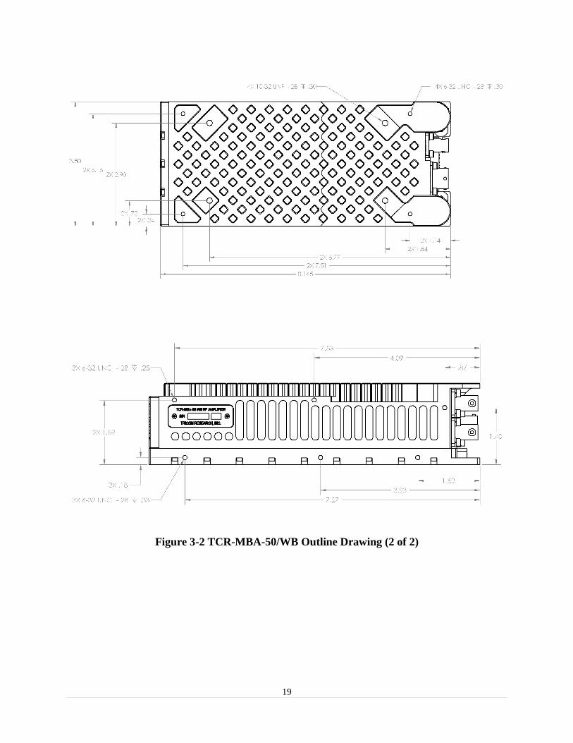
Figure 3-2 TCR-MBA-50/WB Outline Drawing (2 of 2)

20
3.4 DC Input Power.
The DC input power connector is compatible with the TCR-MBA-25 power cables. Attach the
DC power source to the DC IN connector located on the rear of the amplifier (See Fig 3-1 and
Table 3-1 for connector pinout and location).
3.5 RF Interconnections.
Attach an RF cable from the transceiver to the Radio input Connector. Attach RF
cables/antennas to the antenna connections located on the rear of the amplifier (WB antenna
connection is only available on TCR-MBA-50 WB).
Figure 3-3 Amplifier DC input connector (MS3112E10-6P)
Table 3-1. DC Input Power Connector Pinout
Pin # I/O Connection
Pin A I 12-32 VDC
Pin B I GND
Pin C I Commercial Vehicle Select
Pin D I Military Vehicle Select
Pin E I Auto Power ON Select
Pin F I/O Reserved
Table 3-2. DC Input Power Control Pin Functions
Pin C Pin D Description
OC OC Military Battery Mode (12 V nominal)
GND OC Commercial Vehicle Mode (13.8 V nominal)
OC GND Military Vehicle Mode (28 V nominal)
GND GND Reserved
OC = Open Circuit
GND = Ground

21
Figure 3-4 Commercial Vehicle DC Power Cable (part number 77500-00411 optional)
Figure 3-5 Military Vehicle DC Power Cable (part number 77500-00412 included)
Figure 3-6 Military Battery DC Power Cable (part number 77500-00413 optional)
NC
NC
NC
Optional connection for Auto
Power On (green wire)
NC
To side
Contacts
(GND) NC
Remove cap to replace fuse
Replace with 3AG 10A 250 VAC
fast blow fuse
A
B
C
D
E
To tip
MS3116F10-6S
A
B
C
D
E
+28V
GND
MS3116F10-6S
60”
Optional connection for Auto
Power On (green wire)
A
B
C
D
E
60”
4-5
1-2
MS3116F10-6S
60”

22
3.6 Remote Control Interface.
The power amplifier can be controlled via a USB or RS-232 interface using a terminal emulator
such as HyperTerminal. To connect the remote control interface cable, remove the dust cover
labeled AUX CONN on the connector side of the power amplifier. The operating data
parameters for RS-232 are 9600 bps, 8 bits, no parity, and 1 stop bit. To use the USB
connection, follow the Windows instructions to install the appropriate USB driver for a virtual
serial port. The USB driver can be downloaded from
http://www.ftdichip.com/drivers/D2XX.htm.
CAUTION
The AUX CONN cover should be installed whenever the
auxiliary port is not being used to maintain the
environmental integrity of the PA and to prevent damage
to the auxiliary connector contacts.
Figure 3-7 Auxiliary connector pinout (mating connector part number 77500-00421)
Table 3-3 Auxiliary Connector Pinout Pin # I/O Description
1 O RS-232 TXD
2 I RS-232 RXD
3 I USB +5 (used to detect connection to terminal)
4 I/O USB D+
5 I/O USB D-
6 I/O Ground
7 O +5 out @100 mA
8 I EXT SAT/LOS switch relay return (GND= LOS, SAT = OPEN CIRCUIT)
9 I EXT DC on switch (parallels front panel button)
10 O TX indication (GND= RCV, Open Circuit = TX)
11 I/O Reserved 1
12 I/O High in WB and WB HOP modes, low in all other modes
Applies only to TCR-MBA-50 WB
1
2 12
Pictured is the WB version
PA. The Non-WB version
PA has no WB BNC
connector installed

23
+5 VDC
D-
D+ Ground
Figure 3-8 USB Remote Control Cable (part number 77500-00391 optional)
Figure 3-9 RS-232 Remote Control Cable (part number 77500-00390 optional)
60”
3
5
4
6
1
2
3
4
3
5
4
6
60”
1
2
6
2
3
5 Ground
TXD
RXD
2 1

24
3.7 Remote Control Command Set.
Table 3-4 describes the command set for controlling the TCR-MBA-50 (both versions) remotely.
Each valid command is responded with an “ack” message; invalid commands due to
incompatible operational parameters will be responded with a “nack” message and invalid
commands due to syntax errors will be responded with an “unknown command” message.
Table 3-4 Remote Control Command Set COMMAND FUNCTION
remote on Turns on remote control function on the PA (RMT light turns on, mode LOS and SAT
mode switches are disabled)
remote off Turns off remote control mode on the PA (RMT light turns off)
? Displays command list
status Displays current status of the PA (firmware versions, mode, power, temperature)
los fm Selects LOS FM mode
los am Selects LOS AM mode
los fm hop Selects LOS SINCGARS mode
los am hop Selects LOS HAVE QUICK mode
wb Selects LOS WB single frequency mode (does not apply to TCR-MBA-50)
wb hop Selects LOS WB frequency hopping mode (does not apply to TCR-MBA-50)
sat lna on Selects SATCOM mode with LNA turned ON
sat lna off Selects SATCOM mode with LNA turned OFF
power ##w Selects the desired power level where ## is any allowable power level (10, 15, 25, 35,
50) for the selected mode of operation. Selecting a power level that is not allowed
will return a nack message

25
APPENDIX A
MS Windows Serial Comm Port Reassignment
Issue: MS Windows automatically assigns comm ports to USB serial communications devices in
a sequential order. This may create a problem if a remote control Graphical User Interface
(GUI) for the TCR-MBA-50 (both versions) only allows the use of specific comm ports. As an
example, if the GUI only allows the use of COM1, COM2 or COM3 to interface to the PA via
the USB interface and MS Windows automatically assigns COM12 to the USB serial port
adapter embedded in the PA then the PC and the PA will not be able to communicate.
Solution: To resolve this issue, the user may reassign the comm port to the TCR-MBA-50’s
USB serial adapter port (both versions) by going to the advanced comm port settings in the
Device Manager’s menu.
Comm port reassignment procedure:
1. Ensure that the USB driver for the USB to serial adapter in the PA is installed on the
computer. The driver is loaded on the CD that ships with the PA or it can be downloaded
from http://www.ftdichip.com/drivers/D2XX.htm.
NOTE: The driver must be installed first before the PA is connected to the PC.
2. Ensure that the PA is turned OFF.
3. Connect the USB interface cable to the AUXILARY port on the PA and to any available
USB port on the computer.
4. Turn ON the PA.
5. Open the Device Manager on the computer and expand the Ports (COM & LPT) list to
view all enabled comm ports on the computer
6. Double click on the USB Serial Port assigned to the PA (COM12 in this example) to
view/change its settings.
Comm port assigned to PA

26
7. Click on the Port Settings tab and select Advanced…
8. Click on the Comm Port Number: drop down list and select the desired comm port.
9. Click OK on the advanced settings window and verify that the reassigned comm port
settings are 9600 bps, 8 bits, no parity, 1 stop bit and no flow control.
10. Click OK on the USB Serial Port Properties (COM2 in this example) window to return
to the Device Manager main window.
Currently assigned comm port
COM12 Desired comm port COM2

27
11. Verify that the desired comm port (COM2 in this example) is enabled.
12. Exit Device Manager.
13. Run the remote control utility being used to communicate with the TCR-MBA-50 and
verify that the PC is communicating with the PA.
NOTE: Any communications terminal software such as HyperTerminal can be used to
communicate with the PA. Windows 7 does not include the popular HyperTerminal software but
there are several freeware communications terminal emulation utilities available for download on
the internet such as PuTTY, which can be downloaded from http://www.putty.org/.
Reassigned comm port COM2

28
APPENDIX B
Bias Tee Installation Instructions
1. Equipment Preparation.
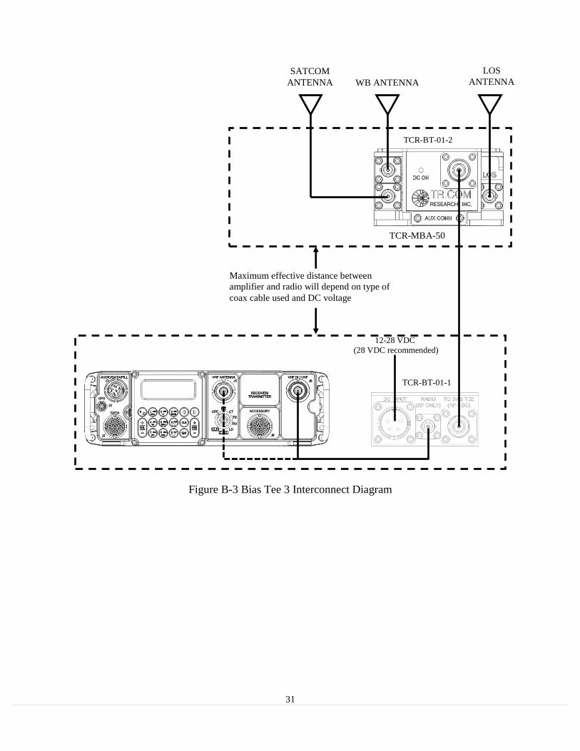
a. Mount TCR-BT-01-2 to the power amplifier as depicted in Figure B-2.
Note: The TCR-BT-01-2 Bias Tee is compatible with both the TCR-MBA-50 and
TCR-MBA-50 WB.
b. Connect the antenna to the appropriate port on the PA (SAT, LOS or WB).
c. Connect RADIO jack on TCR-BT-01-1 to the appropriate radio RF input/output
port as depicted in Figure B-2.
d. Ensure DC power source (28 VDC recommended) is turned off and connect it to
the DC INPUT jack on the TCR-BT-01-1 (see Note 1 below for more information
regarding DC input). Refer to Figure B-1 for DC Power cable pinout.
e. Connect the coax cable between the two N connectors on the TCR-BT-01-1 and
TCR-BT-01-2.
2. Operation.
a. Turn on the DC power source and verify that the DC INPUT LED illuminates on
TCR-BT-01-1 and that DC ON at both Bias Tee ends is OFF.
b. Press and hold the power button on TCR-BT-01-1 until DC ON illuminates (2-3
seconds).
c. Verify that DC ON at TCR-BT-01-2 is also illuminated.
d. Verify that the power amplifier is ON and select the appropriate mode of
operation and power level.
e. Turn on the radio and select the appropriate channel for operation.
f. Key the radio and observe that the TX light on the TCR-BT-01-1and on the power
amplifier illuminate.
g. Refer to Table B-1 for system troubleshooting in the event that any of the steps
above fail to provide the normal indication.
NOTE: The TCR-BT-01-2 is wired for auto start and 28 VDC operation for the TCR-MBA-50
(both versions). The PA will still operate at voltages as low as 12 VDC; however, the current
limiting function for battery or commercial vehicle operation will not be enabled and the PA will
try to TX at higher power levels, up to 50 watts (mode dependent). This will draw higher than
normal current and could potentially trip the overcurrent protection on some batteries, such as
the BA-5590.

29
Figure B-1 Military Vehicle DC Power Cable (part number 1035-77200-00006 included)
Figure B-2 Bias Tee 3 (PA) Installation
60”
A
B
E
C
D
+28V
GND
MS3106A-14S-5S
4 EACH 6-32 X 0.375, 100º
FLAT HEAD SCREW
2 EACH 4-40 X 0.375 100º
FLAT HEAD SCREW

30
Table B-1. Bias Tee 3 Troubleshooting Guide
SYMPTOM PROBABLE CAUSE SUGGESTED FIX
DC INPUT ON
but DC ON at
TCR-BT-01-1
(radio end) does
not illuminate
DC ON at
TCR-BT-01-2 (PA
end) does not
illuminate
TX LED at TCR-
BT-01-01 does not
illuminate when
the radio is keyed
Possible short on coaxial cable
between the two Bias Tees.
Possible open on coaxial cable
between the two Bias Tees.
This condition indicates that the
power amplifier is NOT
drawing any current. PA may be
either turned off or in a fault
condition i.e. wrong frequency
for mode selected on the PA.
Disconnect coaxial cable from
TCR-BT-01-01 and verify that DC ON
illuminates. Replace coaxial cable if
necessary.
Verify that the coaxial cable between
the two Bias Tees is good and properly
connected to the N connectors.
Replace coaxial cable if necessary.
Verify that the PA is turned ON and in
the proper mode of operation.
31
Figure B-3 Bias Tee 3 Interconnect Diagram
SATCOM
ANTENNA
12-28 VDC
(28 VDC recommended)
TCR-BT-01-1
TCR-BT-01-2
TCR-MBA-50
LOS
ANTENNA WB ANTENNA
Maximum effective distance between
amplifier and radio will depend on type of
coax cable used and DC voltage

![IMMUNOGLOBULINE E T CELL RECEPTOR T. Strachan e A.P. … · B cell antigen receptor tetramero [ IgH 2 + IgL 2 (Ig oppure Ig )] T cell receptor (TCR) eterodimero TCR /TCR TCR /TCR](https://static.fdocuments.net/doc/165x107/5c017b5c09d3f26f1e8cc6a0/immunoglobuline-e-t-cell-receptor-t-strachan-e-ap-b-cell-antigen-receptor.jpg)