OPERATOR’S MANUAL - Taylor Company€¦ · OPERATOR’S MANUAL Model C001 & C002 Custard Freezers...
40
OPERATOR’S MANUAL Model C001 & C002 Custard Freezers Original Operating Instructions 055073- M 5/28/08 (Original Publication) (Updated 7/20/15)
Transcript of OPERATOR’S MANUAL - Taylor Company€¦ · OPERATOR’S MANUAL Model C001 & C002 Custard Freezers...

OPERATOR’SMANUAL
Model C001 & C002Custard Freezers
Original Operating Instructions
055073-M 5/28/08 (Original Publication)(Updated 7/20/15)

Complete this page for quick reference when service is required:
Taylor Distributor:
Address:
Phone:
Fax:
E-mail:
Service:
Parts:
Date of Installation:
Information found on the data label:
Model Number:
Serial Number:
Electrical Specs: Voltage Cycle
Phase
Maximum Fuse Size: A
Minimum Wire Ampacity: A
E 2008 Carrier Commercial Refrigeration, Inc.055073-MAny unauthorized reproduction, disclosure, or distribution of copies by any person of any portion of this workmay be a violation of Copyright Law of the United States of America and other countries, could result in theawarding of Statutory Damages of up to $250,000 (17 USC 504) for infringement, and may result in furthercivil and criminal penalties.All rights reserved.
Taylor Companya division of Carrier Commercial Refrigeration, Inc.750 N. Blackhawk Blvd.Rockton, IL 61072

Table of Contents Models C001 & C002
Table of Contents
Section 1 To the Installer 1. . . . . . . . . . . . . . . . . . . . . . . . . . . . . . . . . . . . . . . . . . . .
Installer Safety 1. . . . . . . . . . . . . . . . . . . . . . . . . . . . . . . . . . . . . . . . . . . . . . . . . . . . . . . .
Site Preparation 1. . . . . . . . . . . . . . . . . . . . . . . . . . . . . . . . . . . . . . . . . . . . . . . . . . . . . . .
Air Cooled Units 1. . . . . . . . . . . . . . . . . . . . . . . . . . . . . . . . . . . . . . . . . . . . . . . . . . . . . . .
Water Connections (Water Cooled Units Only) 2. . . . . . . . . . . . . . . . . . . . . . . . . . . .
Electrical Connections 2. . . . . . . . . . . . . . . . . . . . . . . . . . . . . . . . . . . . . . . . . . . . . . . . .
Dasher (Beater) Rotation 3. . . . . . . . . . . . . . . . . . . . . . . . . . . . . . . . . . . . . . . . . . . . . . .
Refrigerant 3. . . . . . . . . . . . . . . . . . . . . . . . . . . . . . . . . . . . . . . . . . . . . . . . . . . . . . . . . . .
Section 2 To the Operator 4. . . . . . . . . . . . . . . . . . . . . . . . . . . . . . . . . . . . . . . . . . .
Section 3 Safety 5. . . . . . . . . . . . . . . . . . . . . . . . . . . . . . . . . . . . . . . . . . . . . . . . . . . .
Section 4 Operator Parts Identification 8. . . . . . . . . . . . . . . . . . . . . . . . . . . . . . .
C001 Exploded View 8. . . . . . . . . . . . . . . . . . . . . . . . . . . . . . . . . . . . . . . . . . . . . . . . . .
C002 Exploded View 10. . . . . . . . . . . . . . . . . . . . . . . . . . . . . . . . . . . . . . . . . . . . . . . . . .
Dasher (Beater) and Door Assembly 12. . . . . . . . . . . . . . . . . . . . . . . . . . . . . . . . . . . . .
Accessories 13. . . . . . . . . . . . . . . . . . . . . . . . . . . . . . . . . . . . . . . . . . . . . . . . . . . . . . . . . .
Section 5 Important: To the Operator 14. . . . . . . . . . . . . . . . . . . . . . . . . . . . . . . . .
C001 14. . . . . . . . . . . . . . . . . . . . . . . . . . . . . . . . . . . . . . . . . . . . . . . . . . . . . . . . . . . . . . . .
C002 15. . . . . . . . . . . . . . . . . . . . . . . . . . . . . . . . . . . . . . . . . . . . . . . . . . . . . . . . . . . . . . . .
Symbol Definitions 16. . . . . . . . . . . . . . . . . . . . . . . . . . . . . . . . . . . . . . . . . . . . . . . . . . . .
Section 6 Operating Procedures 17. . . . . . . . . . . . . . . . . . . . . . . . . . . . . . . . . . . . .
Assembly 17. . . . . . . . . . . . . . . . . . . . . . . . . . . . . . . . . . . . . . . . . . . . . . . . . . . . . . . . . . . .
Sanitizing 20. . . . . . . . . . . . . . . . . . . . . . . . . . . . . . . . . . . . . . . . . . . . . . . . . . . . . . . . . . . .
Priming for Continuous Run 21. . . . . . . . . . . . . . . . . . . . . . . . . . . . . . . . . . . . . . . . . . . .
Stopping a Continuous Run for a Short Period of Time 22. . . . . . . . . . . . . . . . . . . . .
To Restart the Continuous Run: 22. . . . . . . . . . . . . . . . . . . . . . . . . . . . . . . . . . . . . . . . .
Closing Procedure 22. . . . . . . . . . . . . . . . . . . . . . . . . . . . . . . . . . . . . . . . . . . . . . . . . . . .
Draining Product From The Freezing Cylinder 23. . . . . . . . . . . . . . . . . . . . . . . . . . . .
Rinsing 23. . . . . . . . . . . . . . . . . . . . . . . . . . . . . . . . . . . . . . . . . . . . . . . . . . . . . . . . . . . . . .
Cleaning 24. . . . . . . . . . . . . . . . . . . . . . . . . . . . . . . . . . . . . . . . . . . . . . . . . . . . . . . . . . . . .

Table of Contents Models C001 & C002
Table of Contents - Page 2
Disassembly 24. . . . . . . . . . . . . . . . . . . . . . . . . . . . . . . . . . . . . . . . . . . . . . . . . . . . . . . . . .
Brush Cleaning 24. . . . . . . . . . . . . . . . . . . . . . . . . . . . . . . . . . . . . . . . . . . . . . . . . . . . . . .
Section 7 Important: Operator Checklist 26. . . . . . . . . . . . . . . . . . . . . . . . . . . . . .
During Cleaning and Sanitizing 26. . . . . . . . . . . . . . . . . . . . . . . . . . . . . . . . . . . . . . . . .
Troubleshooting Bacterial Count 26. . . . . . . . . . . . . . . . . . . . . . . . . . . . . . . . . . . . . . . .
Regular Maintenance Checks 26. . . . . . . . . . . . . . . . . . . . . . . . . . . . . . . . . . . . . . . . . . .
Winter Storage 27. . . . . . . . . . . . . . . . . . . . . . . . . . . . . . . . . . . . . . . . . . . . . . . . . . . . . . . .
Section 8 Troubleshooting Guide 28. . . . . . . . . . . . . . . . . . . . . . . . . . . . . . . . . . . .
Section 9 Parts Replacement Schedule 31. . . . . . . . . . . . . . . . . . . . . . . . . . . . . . .
Section 10 Limited Warranty on Equipment 32. . . . . . . . . . . . . . . . . . . . . . . . . . . .
Section 11 Limited Warranty on Parts 34. . . . . . . . . . . . . . . . . . . . . . . . . . . . . . . . .
Note: Continuing research results in steady improvements; therefore, informationin this manual is subject to change without notice.
Note: Only instructions originating from the factory or its authorized translationrepresentative(s) are considered to be the original set of instructions.
E 2008 Carrier Commercial Refrigeration, Inc. (Original Publication)(Updated July, 2015)055073-MAny unauthorized reproduction, disclosure, or distribution of copies by any person of any portion of this workmay be a violation of Copyright Law of the United States of America and other countries, could result in theawarding of Statutory Damages of up to $250,000 (17 USC 504) for infringement, and may result in furthercivil and criminal penalties.All rights reserved.
Taylor Companya division of Carrier Commercial Refrigeration, Inc.750 N. Blackhawk Blvd.Rockton, IL 61072

1Models C001 & C002 To the Installer
131122
Section 1 To the Installer
The following information has been included in themanual as safety and regulatory guidelines. Forcomplete installation instructions, please see theInstallation Checklist.
Installer Safety
In all areas of the world, equipment should beinstalled in accordance with existing local codes.Please contact your local authorities if you have anyquestions.
Care should be taken to ensure that all basic safetypractices are followed during the installation andservicing activities related to the installation andservice of Taylor equipment.
S Only authorized Taylor service personnelshould perform installation and repairs on theequipment.
S Authorized service personnel should consultOSHA Standard 29CFRI910.147 or theapplicable code of the local area for theindustry standards on lockout/tagoutprocedures before beginning any installationor repairs.
S Authorized service personnel must ensurethat the proper PPE is available and wornwhen required during installation and service.
S Authorized service personnelmust remove allmetal jewelry, rings, and watches beforeworking on electrical equipment.
The main power supply(s) to the freezer mustbe disconnected prior to performing any repairs.Failure to follow this instruction may result in personalinjury or death from electrical shock or hazardousmoving parts as well as poor performance or damageto the equipment.
Note: All repairs must be performed by anauthorized Taylor Service Technician.
This unit has many sharp edges that cancause severe injuries.
Site Preparation
Review the area where the unit will be installed beforeuncrating the unit. Make sure all possible hazards tothe user or equipment have been addressed.
For Indoor UseOnly: This unit is designed to operateindoors, under normal ambient temperatures of70_-75_F (21_-24_C). The freezer has successfullyperformed in high ambient temperatures of104_(40_C) at reduced capacities.
This unit must NOT be installed in an areawhere a water jet or hose can be used. NEVER use awater jet or hose to rinse or clean the unit. Failure tofollow this instruction may result in electrocution.
This unit must be installed on a level surfaceto avoid the hazard of tipping. Extreme care should betaken in moving this equipment for any reason. Two ormore persons are required to safely move this unit.Failure to comply may result in personal injury orequipment damage.
Uncrate the unit and inspect it for damage. Report anydamage to your Taylor Distributor.
This piece of equipment is made in the USA and hasUSA sizes of hardware. All metric conversions areapproximate and vary in size.
Air Cooled Units
DO NOT obstruct air intake and discharge openings:
Air cooled units require a minimum of 3” (76 mm) ofclearance around all sides of the freezer. Install thedeflector provided to prevent recirculation of warm air.Failure to allow adequate clearance can reduce therefrigeration capacity of the freezer and possiblycause permanent damage to the compressors.

2 Models C001 & C002To the Installer
131021
Water Connections(Water Cooled Units Only)
An adequate cold water supply must be provided witha hand shut- off valve. On the underside rear of thebase pan, two 1/2” (13 mm) I.P.S. water connectionsfor inlet and outlet have been provided for easyhook- up. 1/2” (13 mm) inside diameter water linesshould be connected to the unit. (Flexible lines arerecommended, if local codes permit.) Depending onlocal water conditions, it may be advisable to install awater strainer to prevent foreign substances fromclogging the automatic water valve. There will be onlyone water “in” and one water “out” connection. DONOT install a hand shut- off valve on the water “out”line! Water should always flow in this order: first,through the automatic water valve; second, throughthe condenser; and third, through the outlet fitting to anopen trap drain.
A back flow prevention device is requiredon the incoming water connection side. Pleaserefer to the applicable National, State, and local codesfor determining the proper configuration.
Electrical Connections
In the United States, this equipment is intended to beinstalled in accordance with the National ElectricalCode (NEC), ANSI/NFPA 70- 1987. The purpose ofthe NEC code is the practical safeguarding of personsand property from hazards arising from the use ofelectricity. This code contains provisions considerednecessary for safety. Compliance therewith andproper maintenance will result in an installationessentially free from hazard!
In all other areas of the world, equipment should beinstalled in accordance with the existing local codes.Please contact your local authorities.
FOLLOW YOUR LOCAL ELECTRICAL CODES!
Each freezer requires two dedicated electricalconnections. Check the data label(s) on the freezer forbranch circuit overcurrent protection or fuse, circuitampacity and electrical specifications. Refer to the
wiring diagram provided inside of the electrical box, forproper power connections.
CAUTION: THIS EQUIPMENT MUST BEPROPERLY GROUNDED! FAILURE TO DO SOCAN RESULT IN SEVERE PERSONAL INJURYFROM ELECTRICAL SHOCK!
This unit is provided with an equipotentialgrounding lug that is to be properly attached to the rearof the frameby the authorized installer. The installationlocation is marked by the equipotential bondingsymbol (5021 of IEC 60417-1) on both the removablepanel and the equipment’s frame.
S Stationary appliances which are not equippedwith a power cord anda plugor another deviceto disconnect the appliance from the powersource must have an all-pole disconnectingdevice with a contact gap of at least 3 mminstalled in the external installation.
S Appliances that are permanently connected tofixed wiring and for which leakage currentsmay exceed 10 mA, particularly whendisconnected or not used for long periods, orduring initial installation, shall have protectivedevices such as a GFI, to protect against theleakage of current, installed by the authorizedpersonnel to the local codes.
S Supply cords used with this unit shall beoil-resistant, sheathed flexible cable notlighter than ordinary polychloroprene or otherequivalent synthetic elastomer-sheathed cord(Code designation 60245 IEC 57) installedwith the proper cord anchorage to relieveconductors from strain, including twisting, atthe terminals and protect the insulation of theconductors from abrasion.
If the supply cord is damaged, it must bereplaced by an authorized Taylor servicetechnician in order to avoid a hazard.
3Models C001 & C002 To the Installer
131021
Dasher (Beater) Rotation
Dasher rotation must be clockwise as viewedlooking into the freezing cylinder. As a safety feature,the dasher will not operate without the freezer door inplace.
Note: The following procedures must beperformed by an authorized Taylor servicetechnician.
To correct the rotation on a three- phase unit,interchange any two incoming power supply lines atfreezer main terminal block only.
To correct rotation on a single- phase unit, change theleads inside the dasher motor. (Follow the diagramprinted on the motor.)
Electrical connections are made directly to theterminal block. The terminal block is provided in thecontrol box located behind the lower front panel.
Refrigerant
In consideration of our environment, Taylorproudly uses only earth friendly HFC refrigerants. TheHFC refrigerant used in this unit is R404A. Thisrefrigerant is generally considered non-toxic andnon-flammable, with an Ozone Depleting Potential(ODP) of zero (0).
However, any gas under pressure is potentiallyhazardous and must be handled with caution.
NEVER fill any refrigerant cylinder completely withliquid. Filling the cylinder to approximately 80% willallow for normal expansion.
Use only R404A refrigerant that conforms tothe AHRI standard 700 specification. The use of anyother refrigerant may expose users and operators tounexpected safety hazards.
Refrigerant liquid sprayed onto the skin maycause serious damage to tissue. Keep eyes and skinprotected. If refrigerant burns should occur, flushimmediately with cold water. If burns are severe, applyice packs and contact a physician immediately.
Taylor reminds technicians to be cautious ofgovernment laws regarding refrigerant recovery,recycling, and reclaiming systems. If you have anyquestions regarding these laws, please contact thefactory Service Department.
WARNING: R404A refrigerant used inconjunction with polyolester oils is extremely moistureabsorbent. When opening a refrigeration system, themaximum time the system is openmust not exceed 15minutes. Cap all open tubing to prevent humid air orwater from being absorbed by the oil.

4 Models C001 & C002To the Operator
131122
Section 2 To the Operator
The freezer you have purchased has been carefullyengineered andmanufactured to give you dependableoperation. The Taylor freezer, when properly operatedand cared for, will produceaconsistent quality product.Like all mechanical products, this machine will requirecleaningandmaintenance. Aminimumamount of careand attention is necessary if the operating proceduresoutlined in this manual are followed closely.
This Operator’s Manual should be read beforeoperating or performing any maintenance on yourequipment.
Your Taylor freezer will NOT eventually compensateand correct for any errors during the set- up or fillingoperations. Thus, the initial assembly and primingprocedures are of extreme importance. It is stronglyrecommended that all personnel responsible for theequipment’s operation review these procedures inorder to beproperly trainedand tomakesure that thereis no confusion.
In the event that you should require technicalassistance, please contact your local authorizedTaylor Distributor.
Note: Your Taylor warranty is valid only if the parts areauthorized Taylor parts, purchased from the localauthorized Taylor Distributor, and only if all requiredservice work is provided by an authorized Taylorservice technician. Taylor reserves the right to denywarranty claims on units or parts if non- Taylorapproved parts or incorrect refrigerant were installedin the unit, system modifications were performedbeyond factory recommendations, or it is determinedthat the failure was caused by abuse, misuse, neglect,or failure to follow all operating instructions. For fulldetails of your Taylor Warranty, please see the LimitedWarranty section in this manual.
Note: Constant research results in steadyimprovements; therefore, information in thismanual is subject to change without notice.
If the crossed out wheeled bin symbol isaffixed to this product, it signifies that this product iscompliant with the EUDirective as well as other similarlegislation in effect after August 13, 2005. Therefore,it must be collected separately after its use iscompleted, and cannot be disposed as unsorted
municipal waste. The user is responsible for returningthe product to the appropriate collection facility, asspecified by the local code.
For additional information regarding applicable locallaws, please contact the municipal facility and/or localdistributor.
Compressor Warranty Disclaimer
The refrigeration compressor(s) on this unit arewarranted for the term stated in the Limited Warrantysection in this manual. However, due to the MontrealProtocol and the U.S. Clean Air Act Amendments of1990, many new refrigerants are being tested anddeveloped, thus seeking their way into the serviceindustry. Some of these new refrigerants are beingadvertised as drop- in replacements for numerousapplications. It should be noted that in the event ofordinary service to this unit’s refrigeration system,only the refrigerant specified on the affixed datalabel should be used. The unauthorized use ofalternate refrigerants will void your Taylor compressorwarranty. It is the unit owner’s responsibility to makethis fact known to any technician he employs.
It should also be noted that Taylor does not warrant therefrigerant used in its equipment. For example, if therefrigerant is lost during the course of ordinary serviceto this machine, Taylor has no obligation to eithersupply or provide its replacement either at billable orunbillable terms. Taylor does have the obligation torecommend a suitable replacement if the originalrefrigerant is banned, obsoleted, or no longer availableduring the five year warranty of the compressor.
The Taylor Company will continue to monitor theindustry and test new alternates as they are beingdeveloped. Should a new alternate prove, through ourtesting, that it would be accepted as a drop- inreplacement, then the above disclaimer wouldbecome null and void. To find out the current status ofan alternate refrigerant as it relates to yourcompressor warranty, call the local Taylor Distributoror the Taylor Factory. Be prepared to provide theModel/Serial Number of the unit in question.

5Models C001 & C002 Safety
131021
Section 3 SafetyWe, at Taylor Company, are concerned about thesafety of the operatorwhen heor she comes in contactwith the freezer and its parts. Taylor has gone toextreme efforts to design and manufacture built- insafety features to protect both you and the servicetechnician. As an example, warning labels have beenattached to the freezer to further point out safetyprecautions to the operator.
IMPORTANT - Failure to adhere to thefollowing safety precautions may result in severepersonal injury or death. Failure to comply withthese warnings may damage the machine and itscomponents. Component damage will result inpart replacement expense and service repairexpense.
DONOT operate the freezer without readingthis Operator Manual. Failure to follow this instructionmay result in equipment damage, poor freezerperformance, health hazards, or personal injury.
This unit is to be used only by trainedpersonnel. It is not intended for use by children orpeople with reduced physical, sensory, or mentalcapabilities, or lack of experience and knowledge.Where limited equipment operation is allowed forpublic use, such as a self- serve application,supervision or instruction concerning the use of theappliance by a person responsible for their safety isrequired. Children should be supervised to ensure thatthey do not play with the appliance.
This unit is provided with an equipotentialgrounding lug that is to be properly attached to the rearof the frameby the authorized installer. The installationlocation is marked by the equipotential bondingsymbol (5021 of IEC 60417-1) on both the removablepanel and the equipment’s frame.
DO NOT use a water jet to clean or rinse thefreezer. Failure to follow these instructions may resultin serious electrical shock.
S DO NOT operate the freezer unless it isproperly grounded.
S DO NOT operate the freezer with larger fusesthan specified on the freezer data label.
S All repairs must be performed by anauthorized Taylor service technician. Themain power supplies to the machine must bedisconnected prior to performing any repairs.
S CordConnectedUnits: Only Taylor authorizedservice technicians may install a plug on thisunit.
S Stationary appliances which are not equippedwith a power cord anda plugor another deviceto disconnect the appliance from the powersource must have an all-pole disconnectingdevice with a contact gap of at least 3 mminstalled in the external installation.
S Appliances that are permanently connected tofixed wiring and for which leakage currentsmay exceed 10 mA, particularly whendisconnected or not used for long periods, orduring initial installation, shall have protectivedevices such as a GFI, to protect against theleakage of current, installed by the authorizedpersonnel to the local codes.
S Supply cords used with this unit shall beoil-resistant, sheathed flexible cable notlighter than ordinary polychloroprene or otherequivalent synthetic elastomer-sheathed cord(Code designation 60245 IEC 57) installedwith the proper cord anchorage to relieveconductors from strain, including twisting, atthe terminals and protect the insulation of theconductors from abrasion.
If the supply cord is damaged, it must bereplaced by an authorized Taylor servicetechnician in order to avoid a hazard.
Failure to follow these instructions may result inelectrocution. Contact your local authorized TaylorDistributor for service.

6 Models C001 & C002Safety
131021
S DONOT allow untrained personnel to operatethis machine.
S DONOT operate the freezer unless all servicepanels and access doors are restrained withscrews.
S DO NOT remove the door, dasher, scraperblades, or drive shaft unless the power switchis in the OFF position.
Failure to follow these instructions may result incontaminated product or severe personal injury tofingers or hands from hazardous moving parts.
This unit has many sharp edges that cancause severe injuries.
S DO NOT put objects or fingers in the dooropening. This may contaminate the productand cause severe personal injury from bladecontact.
S USE EXTREME CAUTION when removingthe dasher assembly. The scraper blades arevery sharp and may cause injury.
This freezer must be placed on a levelsurface. Failure to complymay result in personal injuryor equipment damage.
Access to the service area of the unit must berestricted to persons having knowledge and practicalexperience with the unit, in particular as far as safetyand hygiene are concerned.
Cleaning and sanitizing schedules aregoverned by your state or local regulatory agenciesand must be followed accordingly. Please refer to thecleaning section of this manual for the properprocedure to clean this unit.
This unit is designed to maintain producttemperature under 41_F (5_C). Any product beingadded to this unit must be below 41_F (5_C). Failureto follow this instruction may result in health hazardsand poor freezer performance.
DO NOT obstruct air intake and discharge openings:3” (76 mm) minimum air space on all sides. Install thedeflector provided to prevent recirculation of warm air.Failure to follow this instruction may cause poorfreezer performance and damage to the machine.
For Indoor UseOnly: This unit is designed to operateindoors, under normal ambient temperatures of70_-75_F (21_-24_C). The unit has successfullyperformed in high ambient temperatures of up to104_F (40_C) at reduced capacities.
DO NOT run the unit without product. Failure to followthis instruction can result in damage to the unit.
NOISE LEVEL: Airborne noise emission does notexceed 78 dB(A) when measured at a distance of 1.0meter from the surface of the unit and at a height of 1.6meters from the floor.

7Models C001 & C002 Safety
Notes:

8 Models C001 & C002Operator Parts Identification
110304
Section 4 Operator Parts Identification
C001 Exploded View
Figure 1
9Models C001 & C002 Operator Parts Identification
140801
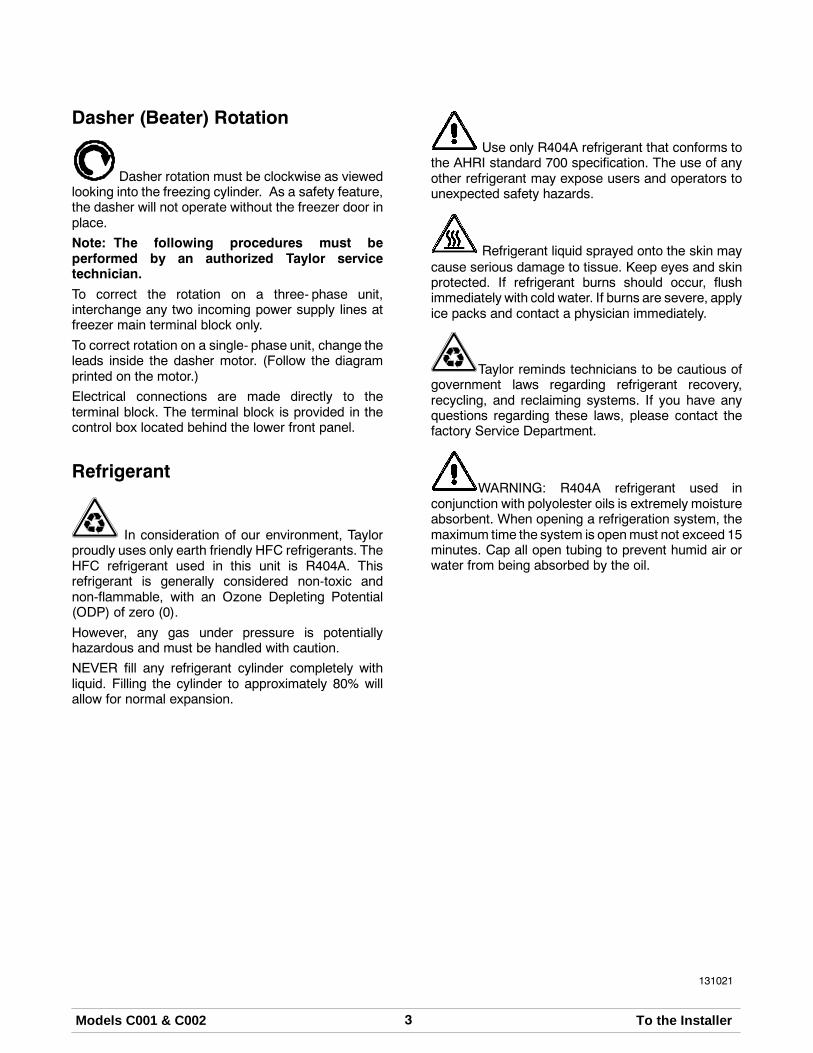
C001 Exploded View Parts Identification
ITEM DESCRIPTION PART NO.
1 PAN-DRIP 11-5/8 LONG 027503
2 GASKET-HOPPER COVER 055356
3 COVER-HOPPER-LARGE 054732
4 COVER-HOPPER-SMALL 054733
5 BUSHING-COVER-HOPPER 054734
6 CONTROL A.-FLOW REG. X59788
6a KNOB-INNER-REG. TUBE 059785
6b O-RING-12.42 MM ID X 1.4 MM 062451
6c PIN-QUICK RELEASE 3/16 X 1 S 027813
6d TUBE-INNER-REGULATOR 059787
6e REGULATOR A.-FLOW OUTER 059784
7 TRIM-REAR CORNER L. 067971
8 PANEL-REAR 066551
9 TRIM-REAR CORNER R. 067972
10 FILTER-AIR-18.00LX13.50HX.70 052779-3
ITEM DESCRIPTION PART NO.
11 SCREW-1/4-20X3/8 SLTD RND 011694
12 ADAPTOR A.-CASTER X18915
13 PANEL-SIDE-RIGHT * A/C 067968
14 NUT-10-32 WHIZ FLANGELOCKNUT
020983
15 DEFLECTOR-BLOWEREXHAUST
047912
16 CASTER-4” SWV 5/8 STEM W/BRAKE
034081
17 PANEL-LOWER FRONT 066544
18 PANEL-SIDE-LEFT *A/C 067967
19 BUMPER 054487
20 CHUTE-CUSTARD-LONG 054633
*21 PANEL A.-FRONT-COMPLETE X66542-27
22 STUD-FREEZER 034035
*PANEL A.-UPPER FRONT (PANEL ONLY) = X66550

10 Models C001 & C002Operator Parts Identification
131021
C002 Exploded View
Figure 2

11Models C001 & C002 Operator Parts Identification
080610
C002 Exploded View Parts Identification
ITEM DESCRIPTION PART NO.
1 PANEL-SIDE TOP 029978
2 COVER-HOPPER-LARGE 054732
3 COVER-HOPPER-SMALL 054733
4 TRIM-REAR CORNER LEFT 054458
5 CONTROL A.-FLOW REG. X59788
5a KNOB-INNER REG. TUBE 059785
5b O-RING-12.42 ID X 1.4 W 062451
5c PIN-QUICK RELEASE 3/16 X 1 027813
5d TUBE-INNER REGULATOR 059787
5e REGULATOR A.-FLOW-OUTER 059784
6 PANEL-REAR 053782
7 PANEL-UPPER SIDE RIGHT 054449
8 PAN-DRIP 11-5/8 LONG 027503
9 TRIM-REAR CORNER RIGHT 054459
10 PANEL A.-SIDE RIGHT X66497
11 NUT-10-32 WHIZ FLANGELOCKNUT
020983
ITEM DESCRIPTION PART NO.
12 DEFLECTOR-BLOWEREXHAUST
047912
13 CASTER-4” SWV 5/8 STEM W/BRAKE
034081
14 ADAPTOR·A.-CASTER X18915
15 PANEL-FRONT-LOWER 066507
16 PANEL A.-SIDE LEFT X66496
17 BUMPER-FRONT 054487
*18 PANEL A.-FRONT-COMPLETE X66509-27
19 STUD-FREEZER 034035
20 PANEL-UPPER SIDE LEFT 054448
21 CHUTE-CUSTARD-LONG 054633
22 GASKET-HOPPER COVER 055356
23 FILTER-AIR 18 L X 13.5 H .70W 052779-3
24 BUSHING-COVER-HOPPER 054734
*PANEL A.-UPPER FRONT (PANEL ONLY) = X66493

12 Models C001 & C002Operator Parts Identification
Dasher (Beater) and Door Assembly
Figure 3
ITEM DESCRIPTION PART NO.
1 CAP-DOOR-STEM 055179
2 ARM-HANDLE 055183
3 PLATE-DRAW 054445
4 O-RING-2-3/4 OD X .139W-70 055182
5 SCREW-DOOR-STEM 055180
6 O-RING-.563 OD X .070W-#013 043758
7 BEARING-FRONT 013116
8 BLADE-SCRAPER 054485
ITEM DESCRIPTION PART NO.
9 BAFFLE-SHORT 054481
10 SHAFT-DASHER DRIVE 054484
11 SEAL-DRIVE SHAFT 032560
12 DASHER A.-COMPLETE X54483
13 O-RING-6 IN OD X 5 3/4 ID X 1/8 033493
14 DOOR-C002 X55178-SER
15 NUT-STUD 034034
16 NUT-STUD 021508

13Models C001 & C002 Operator Parts Identification
140801
Accessories
Figure 4
ITEM DESCRIPTION PART NO.
1 SANITIZER- STERA SHEEN 055492
2 LUBRICANT- TAYLOR 4 OZ. 047518
3 KIT A.- TUNE UP X54630- 1
4 PAIL- 10 QT. 013163
ITEM DESCRIPTION PART NO.
5 BRUSH- REAR BEARING 013071
6 BRUSH- DOUBLE ENDED 013072
7 BRUSH- MIX PUMP BODY 023316
8 BRUSH- DRAW VALVE 013073

14 Models C001 & C002Important: To the Operator
110304
Section 5 Important: To the Operator
C001
Figure 5
ITEM DESCRIPTION
1 LIGHT- HOPPER REFRIG. ON/OFF
2 SWITCH- HOPPER REFRIG. ON/OFF
3 LIGHT- MIX LOW
4 LIGHT- FREEZE MODE
5 SWITCH- FREEZE/CHILL MODE
ITEM DESCRIPTION
6 LIGHT- CHILL MODE
7 LIGHT- DASHER ON/OFF
8 SWITCH- DASHER ON/OFF
9 BUTTON- RESET

15Models C001 & C002 Important: To the Operator
080930
C002
Figure 6
ITEM DESCRIPTION
1 LIGHT- HOPPER REFRIG. ON/OFF
2 SWITCH- HOPPER REFRIG. ON/OFF
3 LIGHT- MIX LOW
4 LIGHT- FREEZE MODE
5 SWITCH- FREEZE/CHILL MODE
ITEM DESCRIPTION
6 LIGHT- CHILL MODE
7 LIGHT- DASHER ON/OFF
8 SWITCH- DASHER ON/OFF
9 BUTTON- RESET

16 Models C001 & C002Important: To the Operator
Symbol Definitions
To better communicate in the International arena, thewords on many of our operator switches and buttonshave symbols to indicate their functions. Your Taylorequipment is designed with these Internationalsymbols.
The following chart identifies the symbol definitionsused on the operator switches.
= HOPPER REFRIGERATION
= ON
= OFF
= MIX LOW
= FREEZE MODE
= CHILL MODE
= DASHER

17Models C001 & C002 Operating Procedures
Section 6 Operating Procedures
The Model C001 is a single flavor custard freezer witha 20 quart (18.9 liter) hopper. TheModel C002 is a twoflavor custard freezer with two 20 quart (18.9 liter)hoppers. Mix flows by gravity through an adjustableflow regulator into the freezing cylinder(s). These unitshave been designed to produce rich tasting custardproduct that can be drawn off and served from adipping cabinet. The overrun is low; typically 15- 20%,and varies depending on the mix formulation and thefinished product temperature 17 to 19_.F (- 8.3 to- 7.2_C).
The Model C002 has been selected to illustrate thepictured step- by- step operating procedures for bothmodels contained in this manual. These models, forpractical purposes of operation, are the same.
We begin our instructions at the point where we findthe parts disassembled and laid out to air dry from theprevious brush cleaning.
The following procedures will show you how toassemble the parts into the freezer, sanitize them, andprime the freezer with fresh mix.
If you are disassembling the freezer for the first timeor need information to get to this starting point in ourinstructions, turn to page 24 , “Disassembly” and startthere.
Assembly
MAKE SURE THE DASHER POWERSWITCH IS IN THE “OFF” POSITION. Failure tofollow this instruction may cause severe personalinjury to fingers or hands from hazardous movingparts.
Step 1Install the drive shaft. Lubricate thegroove andshaftportion that comes in contact with the bearing on thedasher drive shaft. Slide the seal over the shaft andgroove until it snaps into place. DO NOT lubricate thehex end of the drive shaft. Fill the inside portion of theseal with 1/4” (6 mm) more lubricant and lubricate theflat side of the seal that fits onto the rear shell bearing.
Note: When lubricating parts, always use anapproved food grade lubricant (example: TaylorLube).
Figure 7
Insert the drive shaft into the freezing cylinder, hex endfirst, and into the rear shell bearing until the seal fitssecurely over the rear shell bearing. Engage the hexend firmly into the drive coupling. Be sure the driveshaft fits into the drive coupling without binding.
Figure 8

18 Models C001 & C002Operating Procedures
090106
Step 2Install the short baffle into the freezing cylinder, narrowend first. Slide it over the end of the drive shaft.
Figure 9
Step 3Assemble thedasher.Takeoneof the scraper bladesand slip it under the hook at the front of the dasher.Wrap the blade around the dasher, following the helixand pushing the blade down onto the helix as youwrap. At the back end of the dasher, slip the bladeunder the hook. Repeat this step for the other scraperblades.
Figure 10
Step 4Install the dasher. Slide the dasher into the freezingcylinder andover theendof thedrive shaft. Thedashershould fit snugly, but not so tightly that the dashercannot be turned slightly to engage the drive shaft. Ifthe dasher slides in too easily with little or noresistance, there will not be enough force against thedasher to hold the blades in place. If this is the case,contact your authorized Taylor service technician.
Figure 11
Note: A dasher installation/removal tool is availableto assist in the installation and removal of the dasher.To install the dasher, insert the short bars of the toolinto the slots in the end of the dasher. Using the longbar of the tool, push the dasher until it is properlyinstalled in the freezing cylinder.
Figure 12
Install the front bearing into the front of the dasherassembly.
11197
Figure 13

19Models C001 & C002 Operating Procedures
Step 5Assemble the freezer door. Install the draw plateo- ring onto the plate and lubricate.
L
UB E
R
10317
Figure 14
Install the two stem screwo- rings onto the stemscrewand lubricate.
R
10329
Figure 15
Place the stem screw through the back of the door.With the door in a horizontal position, install the drawplate. Align the handle with the stem screw and thedraw plate. Hand- tighten the stem cap onto the stemscrew.
10328
Figure 16
Turn the door over and install the large door o- ring.Place a small amount of lubricant on the o- ring, justenough to hold the o- ring in place.
R
10325
Figure 17
Step 6Install the freezer door. Seat the door flush with thefreezing cylinders. With the door seated on the freezerstuds, install the stud nuts (handscrews). The shortstud nuts go on the bottom and the long stud nuts goon top. Tighten equally in a crisscross pattern to insurethe door is snug.
10326
Figure 18

20 Models C001 & C002Operating Procedures
140801
Step 7Assemble the flow regulator assembly. Install thetwo o- rings onto the inner flow regulator. Lubricate theo- rings. Install the knob onto the end of the inner flowregulator and secure it with the quick release pin.Insert the inner flow regulator into the outer flowregulator.
Figure 19
Step 8Place the assembled flow regulator into the hopper forsanitizing.
Step 9Install the rear bearing drip pan.
Step 10Put the sanitized hopper gasket on the hopper cover.
17042
Figure 20
Repeat thesesteps for theother sideof the freezer.
Sanitizing
Step 1Prepare an approved 100 PPM sanitizing solution(examples: 2- 1/2 gal. [9.5 liters] of Kay- 5Ror 2 gal. [7.6 liters] of Stera- SheenR). USE WARMWATER AND FOLLOW THE MANUFACTURER’SSPECIFICATIONS.
Step 2Pour the sanitizing solution into the hopper.
Step 3While the solution is flowing into the freezing cylinder,brush clean the mix hopper. When cleaning thehopper, take particular care in brushing the mix inlethole and the flow regulator.
Step 4Place an empty pail under the draw plate. The pail canbe hung from the hand screws on the freezer door.
Step 5Place the dasher motor power switch in the ONposition for 5 minutes.
Step 6In order to avoid having sanitizer splashing out whenthe draw plate is opened, place the dasher motorswitch in the OFF position. Open the draw plate andplace thedashermotor switch in theONposition.Drainthe sanitizer into anempty pail. Place thedashermotorswitch in the OFF position and close the draw plate.
KEEP FINGERS OUT OF FILL ANDDISCHARGEOPENINGS! Failure to do somay resultin severe personal injury, contaminated product, orcomponent damage.
Repeat thesesteps for theother sideof the freezer.

21Models C001 & C002 Operating Procedures
140801
Priming for Continuous Run
Step 1With sanitized hands, remove the flow regulatorassembly from themix hopper and set it on a clean, drysurface. Place an empty pail under the draw plate.
Step 2Pour 1 - 2 cups (1/2 liter) of mix into the hopper toremove the remaining sanitizing solution from thefreezing cylinder.
Step 3Open the draw plate on the freezer door and place thedasher motor power switch in the ON position.
Repeat steps 1 - 2 for the other side of the freezer.
KEEP FINGERS OUT OF FILL ANDDISCHARGEOPENINGS! Failure to do somay resultin severe personal injury, contaminated product, orcomponent damage.
Step 4Install the large hopper cover on the hopper.
Step 5With sanitized hands, install the flow regulatorthrough the hopper cover. Align the flow regulator withthe slots on the hopper cover. The flow regulator canbe positioned to allow the numbers to be read from thefront, back or either side.
Step 6Pour mix into the hopper and fill it to 1/2” (13 mm)below the air inlet on the flow regulator.
Step 7Place the FREEZE/CHILL switch in the FREEZEposition and the hopper refrigeration switch in the ONposition.
Step 8Allow the unit to run for 2 minutes. Set the flowregulator between S - 1.
Step 9Install the small hopper lid.
Repeat steps 4 - 9 for the other side of the freezer.
Note: The flow regulator opening is adjustable. Thesmaller the number, the less product will flow into thefreezing cylinder. The larger the number, the moreproduct will flow into the freezing cylinder. Thenumbers are only guides. The flow regulator may beadjusted to any point in between the numbers.
Figure 21
Step 10Install the chute on the two holding collars under thedoor and position it over the holding cabinet opening.
Figure 22
Step 11Leave the draw plate closed until product can be seencoming out around the edges of the draw plate(approximately 3 to 4minutes) and then open thedrawplate all the way.

22 Models C001 & C002Operating Procedures
Step 12With the draw plate open and a full ribbon of productdispensing at the proper frozen consistency, the flowregulator will need to be opened further to prevent thefreezing cylinder from starving.
IMPORTANT: If the freezing cylinder becomesstarved and begins to make noise, increase thenumber on the flow regulator. Wait one or twominutes.If the noise continues, place the FREEZE/CHILLswitch in the OFF position until product begins flowingfrom the door. Place the FREEZE/CHILL switch backin the FREEZE mode position. Repeat these steps asnecessary to adjust for a specific mix. DO NOT TURNDASHER OFF!
If the product becomes too soft, decrease the flowregulator opening.
Repeat steps 10 - 12 for the other side of thefreezer.
Stopping a Continuous Run for aShort Period of TimeStep 1Leave the flow regulator in the DOWN position, butadjust the setting to 0. Wait 30 seconds.
Step 2Place the FREEZE/CHILL switch in the CHILL modeposition. Wait two minutes.
Step 3Place the dasher power switch in the OFF position.
Step 4Close the draw plate.
WARNING: The dasher motor powerswitch must be placed in the OFF position whenthe draw plate is closed. Failure to comply can resultin serious equipment damage and possible injury tothe operator.
To Restart the Continuous Run:
Step 1Place the dasher power switch in the ON position.
Step 2Place the FREEZE/CHILL switch in the FREEZEmode position. Wait one minute.
Step 3Open the flow regulator back to the previous runsetting.
Step 4Once product starts coming out around the edges ofthe draw plate, open the draw plate.
Closing Procedure
To disassemble your unit, the following items will beneeded:
S Two cleaning pailsS Necessary brushes (provided with freezer)S CleanerS Single service towels

23Models C001 & C002 Operating Procedures
140801
Draining Product From TheFreezing Cylinder
Step 1Place the FREEZE/CHILL and the hopperrefrigeration switches in the OFF position.
Step 2Remove the flow regulator assembly, hopper covers,gaskets, discharge chute and rear bearing drip pan.Take these parts to the sink for cleaning in anapproved cleaning solution (examples: Kay- 5R orStera- SheenR).
Step 3If local health codes permit the use of rerun, placea sanitized, NSF approved stainless steel reruncontainer beneath the draw plate. Place the dasherpower switch in the ON position. Drain the remainingproduct into the rerun container. When the flow ofproduct stops, place the dasher power switch in theOFF position. Place the sanitized lid on the reruncontainer and place it in the walk- in cooler.
Note: If local health codesDONOTpermit theuseof rerun, the productmust bediscarded. Follow theinstructions in the previous step, except drain theproduct into a pail and properly discard the mix.
Repeat steps 1 through 3 for the other side of thefreezer.
ALWAYS FOLLOW LOCAL HEALTH CODES.
Rinsing
Step 1With a pail beneath the draw plate, pour two gallons(7.6 liters) of cool clean water into the mix hopper.With the brushes provided, scrub the mix hopper.
Figure 23
Step 2Place the dasher motor power switch in the ONposition. Agitate for five minutes. Drain all the rinsewater from the freezing cylinder.
Repeat steps 1 through 2 until the water is clear.
Step 3Once all the rinse water has drained, place the dashermotor power switch in the OFF position.
Repeat steps 1 through 3 for the other side of thefreezer.

24 Models C001 & C002Operating Procedures
090106
Cleaning
Step 1Prepare an approved 100 PPM cleaning solution(examples: 2- 1/2 gal. [9.5 liters] of Kay- 5Ror 2 gal. [7.6 liters] of Stera- SheenR). USE WARMWATER AND FOLLOW THE MANUFACTURER’SSPECIFICATIONS.
Step 2With the draw plate closed, pour the cleaning solutioninto the mix hopper.
Figure 24
Step 3While the solution is flowing into the freezing cylinder,brush clean the mix hopper.
Step 4Place an empty pail beneath the draw plate.
Step 5Place the dasher motor switch in the ON position.
Step 6Allow all of the solution to drain.
Repeat steps 1 through 6 for the other side of thefreezer.
Disassembly
MAKE SURE THE DASHER POWERSWITCH IS IN THE “OFF” POSITION. Failure tofollow this instruction may result in severe personalinjury to fingers or hands from hazardous movingparts.
Step 1Remove the flow regulators from the mix hoppers.Remove the handscrews, freezer doors, dashers,scraper blades, chutes, and drive shafts from thefreezing cylinders. Take these parts to the sink forcleaning.
Note: A dasher installation/removal tool is availableto assist in the installation and removal of the dasher.To remove the dasher, insert the two short bars of thetool into the slots in the end of the dasher. Holding thelong bar of the tool, turn the tool clockwise to lock thetool in the dasher, and then pull the dasher out.
Figure 25
Brush Cleaning
Step 1Prepare a sink with an approved cleaning solution(examples: Kay- 5R or Stera- SheenR). USEWARMWATER AND FOLLOW THE MANUFACTURER’SSPECIFICATIONS. If another approved cleaner isused, dilute it according to the label instructions.(IMPORTANT: Follow the label directions. TooSTRONG of a solution can cause parts damage, whiletoo MILD of a solution will not provide adequatecleaning.) Make sure all brushes provided with thefreezer are available for brush cleaning.

25Models C001 & C002 Operating Procedures
Step 2Remove the seals from the drive shafts.
Figure 26
Step 3From the freezer door remove:
S front bearingsS handle armsS platesS stem capsS stem screws
Step 4Remove all o- rings.
Note: To remove o- rings, use a single service towelto grasp the o- ring. Apply pressure in an upwarddirection until the o- ring pops out of its groove. Withthe other hand, push the top of the o- ring forward andit will roll out of the groove and can be easily removed.If there is more than one o- ring to be removed, alwaysremove the rear o- ring first. This will allow the o- ringto slide over the forward rings without falling into theopen grooves.
Step 5Remove the o- rings from the inner flow regulators.
Figure 27
Step 6Remove the hopper cover gasket from the hoppercover.
Step 7Return to the freezer with a small amount of cleaningsolution. Brush clean the mix inlet holes in the mixhoppers.
Figure 28
Step 8Brush clean the rear shell bearings at the back of thefreezing cylinders with the black bristle brush.
Figure 29
Step 9Thoroughly brush clean all disassembled parts in thecleaning solution,making sure all lubricant andmix filmis removed. Place all the cleaned parts on a clean, drysurface to air dry overnight.
Step 10Wipe clean all exterior surfaces of the freezer.
26 Models C001 & C002Important: Operator Checklist
Section 7 Important: Operator Checklist
During Cleaning and Sanitizing
ALWAYS FOLLOW LOCAL HEALTH CODES.
Cleaning and sanitizing schedules are governedby federal, state, or local regulatory agencies, andmust be followed accordingly. If the unit has a“Standby mode”, it must not be used in lieu ofproper cleaning and sanitizing procedures andfrequencies set forth by the ruling healthauthority. The following check points should bestressed during the cleaning and sanitizingoperations.
CLEANING AND SANITIZING MUST BEPERFORMED DAILY.
Troubleshooting Bacterial Count
j 1. Thoroughly clean and sanitize the machineregularly, including complete disassembly andbrush cleaning.
j 2. Use all brushes supplied for thorough cleaning.The brushes are specially designed to reach allmix passageways.
j 3. Use the white bristle brush to clean the mix inlethole which extends from the mix hopper downto the rear of the freezing cylinder.
j 4. Use the black bristle brush to thoroughly cleanthe rear shell bearing located at the rear of thefreezing cylinder. Be sure there is a generousamount of cleaning solution on the brush.
j 5. IF LOCAL HEALTH CODES PERMIT THEUSE OF RERUN, make sure the mix rerun isstored in a sanitized, covered stainless steelcontainer and used the following day. DO NOTprime the machine with rerun. When usingrerun, skim off the foam and discard. Mix thererunwith freshmix in a ratio of 50/50 during thedays operation.
j 6. On a designated day of theweek, run themix aslow as feasible and discard it after closing. Thiswill break the rerun cycle and reduce thepossibility of high bacteria and coliform counts.
j 7. Properly prepare the cleaning and sanitizingsolutions. Read and follow the label directionscarefully. Too strong of a solution may damagethe parts and too weak of a solution will not doan adequate job of cleaning or sanitizing.
j 8. The temperature of the mix in the mix hopperand walk- in cooler should be below 40_F(4.4_C).
Regular Maintenance Checks
j 1. Replace scraper blades that are nicked ordamaged. Before installing the dasherassembly, be certain that the scraper blades areproperly attached to the dasher shaft.
j 2. Check the rear shell bearing for signs of wear(excessive mix leakage in rear drip pan) and becertain it is properly cleaned.
j 3. Using a long brush and a cloth towel, keep therear shell bearing and the female hex drivesocket clean and free of lubricant and mixdeposits.
j 4. Dispose of o- rings and seals if they are worn,torn, or fit too loosely, and replace with newones.

27Models C001 & C002 Important: Operator Checklist
080130
j 5. Follow all lubricating procedures as outlined in“Assembly”.
j 6. If your machine is air cooled, check thecondenser for an accumulation of dirt and lint.Dirty condensers will reduce the efficiency andcapacity of themachine. Condensers should becleaned monthly with a soft brush. Never usescrewdrivers or other metal probes to cleanbetween the fins.Note: For machines equipped with an air filter,it will be necessary to vacuum the filters on amonthly schedule.
Caution: Always disconnectelectrical power prior to cleaning thecondenser. Failure to follow this instruction mayresult in electrocution.
j 7. If yourmachine iswater cooled, check thewaterlines for kinks or leaks. Kinks can occur whenthe machine is moved back and forth forcleaning or maintenance purposes.Deteriorated or cracked water lines should bereplaced only by an authorized Taylordistributor.
Winter Storage
If the placeof business is to be closedduring thewintermonths, it is important to protect the freezer byfollowing certain precautions, particularly if thebuilding is subject to freezing conditions.
Disconnect the freezer from the main power source toprevent possible electrical damage.
On water cooled freezers, disconnect the watersupply. Relieve pressure on the spring in the watervalve. Use air pressure on the outlet side to blow outany water remaining in the condenser. This isextremely important. Failure to follow this proceduremay cause severe and costly damage to therefrigeration system.
Your local Taylor Distributor can perform this winterstorage service for you.
Wrap detachable parts of the freezer such as dasher,blades, dasher shaft, and freezer door, and place theminaprotecteddry place. Rubber trimparts andgasketscan be protected by wrapping them withmoisture- proof paper. All parts should be thoroughlycleaned of dried mix or lubrication which attract miceand other vermin.
It is recommended that an authorized servicetechnician perform winter storage draining, to insureall water has been removed. This will guard againstfreezing and rupturing of the components.

28 Models C001 & C002Important: Operator Checklist
Section 8 Troubleshooting Guide
PROBLEM PROBABLE CAUSE REMEDY PAGEREF.
1. Compressor will not run. a. Dasher motor switchand/or FREEZE/CHILLswitch are in the wrongposition.
a. Place the dasher motorswitch and/or theFREEZE/CHILL switch inthe “FREEZE” position.
15
b. The contactor is faulty. b. Call service technician. - - -
c. Compressor has burnedout.
c. Call service technician. - - -
d. The fuse or circuit breakerhas blown.
d. Replace fuse/turn onbreaker.
2
e. Tripped overload(compressor).
e. Place the power switch in“OFF”. Allow compressorto cool and the overload toclose before returning thepower switch to “ON”.
- - -
f. Freezer door is off. f. Install the freezer door. 19
2. Head pressure is too high. a. Condenser is dirty. a. Clean the condenser. 27
b. Refrigerant overcharge. b. Call service technician. - - -
c. Fan is faulty. c. Call service technician. - - -
3. Head pressure is too low. a. Shortage of refrigerant. a. Call service technician. - - -
4. Liquid line is hot. a. Shortage of refrigerant. a. Call service technician. - - -
5. Excessive mix leakagethrough the rear of theunit into the drip pan.
a. Worn or missing driveshaft seal.
a. Replace worn, nicked ormissing drive shaft seal.
17
b. Inadequate lubrication. b. Lubricate properly. 17
6. Product is not being fedinto the freezing cylinder.
a. Inadequate mix in hopper.(mix out light illuminated)
a. Fill hopper with mix. 21
b. Incorrect usage of the mixflow regulator.
b. Follow the correct flowregulator adjustmentprocedures.
21

29Models C001 & C002 Important: Operator Checklist
PROBLEM PROBABLE CAUSE REMEDY PAGEREF.
7. No product is beingdispensed with the flowcontrol open.
a. Frozen product. a. Scrape product away fromthe door.
- - -
b. Dasher is rotatingcounter- clockwise.
b. Call service technician. - - -
c. Inadequate mix in hopper.(mix out light illuminated)
c. Fill hopper with mix. 21
d. Flow regulator is plugged. d. Brush clean the flowregulator.
25
8. Product is too soft. a. Bad scraper blades. a. Replace scraper blades. 18
b. Dirty condenser(air- cooled).
b. Clean condenser monthly. 27
c. Mix is outdated. c. Use fresh mix. - - -
d. Refrigerant shortage. d. Call service technician. - - -
e. Flow regulator setting istoo high.
e. Call service technician. - - -
9. Door spout is plugged. a. Poor scraping. a. Replace scraper blades. 18
b. The dasher assembly isdamaged.
b. Inspect and replace ifnecessary.
18
10. No freezer operationwhen unit is placed in anymode of operation.
a. The unit is unplugged. a. Plug in the unit. - - -
b. Circuit breaker is off orfuse is blown.
b. Turn on the circuit breaker/ replace fuse.
- - -
11. Product is too stiff. a. Flow regulator is set toolow.
a. Adjust the flow regulatorsetting.
21
b. Flow regulator isincorrectly assembled oris malfunctioning.
b. Re- assemble the flowregulator. If flow regulatormalfunctions, call servicetechnician.
20
12. The mix in the hopper istoo cold.
a. Temperature is out ofadjustment.
a. Call service technician. - - -
13. The mix in the hopper istoo warm.
a. Temperature is out ofadjustment.
a. Call service technician. - - -

30 Models C001 & C002Important: Operator Checklist
PROBLEM PROBABLE CAUSE REMEDY PAGEREF.
14. Drive shaft is stuck in thegear box coupling.
a. The corners of the driveshaft, coupling, or bothare rounded.
a. Replace the necessarycomponent(s). Do notlubricate the end of thedrive shaft.
17
b. Mix and lubricant havecollected in the drivecoupling.
b. Brush clean the rear shellbearing area regularly.
25
15. Freezing cylinder wallsare scored.
a. The dasher assembly isdamaged.
a. Replace the dasherassembly.
18
b. The front bearing is eithermissing or is worn.
b. Install / replace frontbearing.
18
16. A “chirping” or squealingsound is coming from thefreezing cylinder.
a. The freezing cylinder isstarved for mix.
a. Adjust the flow control toallow more mix to enterthe freezing cylinder.
21
17. The reset is tripping. a. The belt is too tight. a. Call service technician. - - -
b. The amperage is too high. b. Call service technician. - - -
c. The dasher is rotatingcounter- clockwise.
c. Call service technician. - - -
d. Faulty reset switch. d. Call service technician. - - -
e. The suction pressure istoo low.
e. Call service technician. - - -
f. The shaft is too far intothe gearbox or is pushingon the door.
f. Call service technician. - - -
g. Product is frozen in thefreezing cylinder.
g. Call service technician. - - -

31Models C001 & C002 Parts Replacement Schedule
Section 9 Parts Replacement Schedule
PART DESCRIPTION EVERY 3MONTHS
EVERY 6MONTHS
ANNUALLY
Front Bearing X
Inner Flow Regulator O- Rings X
Draw Plate O- Ring X
Freezer Door O- Ring X
Drive Shaft Seal X
Scraper Blades X
Black Bristle Brush - 1” x 2” Inspect & Replaceif Necessary
Minimum
Double Ended Brush Inspect & Replaceif Necessary
Minimum
White Bristle Brush - 3” x 7” Inspect & Replaceif Necessary
Minimum

32 Models C001 & C002Limited Warranty on Equipment
131122
Section 10 Limited Warranty on Equipment
TAYLOR COMPANY LIMITED WARRANTY ON FREEZERS
Taylor Company, a division of Carrier Commercial Refrigeration, Inc. (“Taylor”) is pleased to provide this limitedwarranty on new Taylor-branded freezer equipment available from Taylor to the market generally (the “Product”)to the original purchaser only.
LIMITED WARRANTY
Taylor warrants the Product against failure due to defect in materials or workmanship under normal use andservice as follows. All warranty periods begin on the date of original Product installation. If a part fails due todefect during the applicable warranty period, Taylor, through an authorized Taylor distributor or service agency,will provide a new or re- manufactured part, at Taylor’s option, to replace the failed defective part at no charge forthe part. Except as otherwise stated herein, these are Taylor’s exclusive obligations under this limited warranty fora Product failure. This limited warranty is subject to all provisions, conditions, limitations and exclusions listedbelow and on the reverse (if any) of this document.
Product Part Limited Warranty Period
Soft ServeFrozen YogurtShakesSmoothies
Frozen BeverageBatch Desserts
Insulated shell assembly Five (5) years
Refrigeration compressor(except service valve)
Five (5) years
Beater motors Two (2) years
Beater drive gear Two (2) years
Printed circuit boards andSoftech controls beginningwith serial number H8024200
Two (2) years
Parts not otherwise listed inthis table or excluded below
One (1) year
LIMITED WARRANTY CONDITIONS
1. If the date of original installation of the Product cannot be verified, then the limited warranty period beginsninety (90) days from the date of Product manufacture (as indicated by the Product serial number). Proof ofpurchase may be required at time of service.
2. This limited warranty is valid only if the Product is installed and all required service work on the Product isperformed by an authorized Taylor distributor or service agency, and only if genuine, new Taylor parts areused.
3. Installation, use, care, and maintenance must be normal and in accordance with all instructions contained inthe Taylor Operator’s Manual.
4. Defective parts must be returned to the authorized Taylor distributor or service agency for credit.
5. The use of any refrigerant other than that specified on the Product’s data label will void this limited warranty.
LIMITED WARRANTY EXCEPTIONS
This limited warranty does not cover:
1. Labor or other costs incurred for diagnosing, repairing, removing, installing, shipping, servicing or handling ofdefective parts, replacement parts, or new Products.
2. Normal maintenance, cleaning and lubrication as outlined in the Taylor Operator’s Manual, including cleaningof condensers.

33Models C001 & C002 Limited Warranty on Equipment
3. Replacement of wear items designated as Class “000” parts in the Taylor Operator’s Manual.
4. External hoses, electrical power supplies, and machine grounding.
5. Parts not supplied or designated by Taylor, or damages resulting from their use.
6. Return trips or waiting time required because a service technician is prevented from beginning warrantyservice work promptly upon arrival.
7. Failure, damage or repairs due to faulty installation, misapplication, abuse, no or improper servicing,unauthorized alteration or improper operation or use as indicated in the Taylor Operator’s Manual, includingbut not limited to the failure to use proper assembly and cleaning techniques, tools, or approved cleaningsupplies.
8. Failure, damage or repairs due to theft, vandalism, wind, rain, flood, high water, water, lightning, earthquakeor any other natural disaster, fire, corrosive environments, insect or rodent infestation, or other casualty,accident or condition beyond the reasonable control of Taylor; operation above or below the electrical orwater supply specification of the Product; or components repaired or altered in any way so as, in thejudgment of the Manufacturer, to adversely affect performance, or normal wear or deterioration.
9. Any Product purchased over the Internet.
10. Failure to start due to voltage conditions, blown fuses, open circuit breakers, or damages due to theinadequacy or interruption of electrical service.
11. Electricity or fuel costs, or increases in electricity or fuel costs from any reason whatsoever.
12. Damages resulting from the use of any refrigerant other than that specified on the Product’s data label willvoid this limited warranty.
13. Any cost to replace, refill or dispose of refrigerant, including the cost of refrigerant.
14. ANY SPECIAL, INDIRECT OR CONSEQUENTIAL PROPERTY OR COMMERCIAL DAMAGE OF ANYNATURE WHATSOEVER. Some jurisdictions do not allow the exclusion of incidental or consequentialdamages, so this limitation may not apply to you.
This limited warranty gives you specific legal rights, and you may also have other rights which vary fromjurisdiction to jurisdiction.
LIMITATION OF WARRANTY
THIS LIMITED WARRANTY IS EXCLUSIVE AND IS IN LIEU OF ALL OTHER WARRANTIES, CONDITIONSAND/OR REMEDIES UNDER THE LAW, INCLUDING ANY IMPLIED WARRANTIES OR CONDITIONS OFMERCHANTABILITY OR FITNESS FOR A PARTICULAR PURPOSE. THE ORIGINAL OWNER’S SOLEREMEDY WITH RESPECT TO ANY PRODUCTS SHALL BE REPAIR OR REPLACEMENT OF DEFECTIVECOMPONENTS UNDER THE TERMS OF THIS LIMITED WARRANTY. ALL RIGHTS TO CONSEQUENTIALOR INCIDENTAL DAMAGES (INCLUDING CLAIMS FOR LOST SALES, LOST PROFITS, PRODUCT LOSS,PROPERTY DAMAGES OR SERVICE EXPENSES) ARE EXPRESSLY EXCLUDED. THE EXPRESSWARRANTIES MADE IN THIS LIMITED WARRANTY MAY NOT BE ALTERED, ENLARGED, OR CHANGEDBY ANY DISTRIBUTOR, DEALER, OR OTHER PERSON, WHATSOEVER.
LEGAL REMEDIES
The owner must notify Taylor in writing, by certified or registered letter to the following address, of any defect orcomplaint with the Product, stating the defect or complaint and a specific request for repair, replacement, or othercorrection of the Product under warranty, mailed at least thirty (30) days before pursuing any legal rights orremedies.
Taylor Companya division of Carrier Commercial Refrigeration, Inc.
750 N. Blackhawk Blvd.Rockton, IL 61072, U.S.A.

34 Models C001 & C002Limited Warranty on Parts
131122
Section 11 Limited Warranty on Parts
TAYLOR COMPANY LIMITED WARRANTY ON TAYLOR GENUINE PARTS
Taylor Company, a division of Carrier Commercial Refrigeration, Inc. (“Taylor”) is pleased to provide this limitedwarranty on new Taylor genuine replacement components and parts available from Taylor to the market generally(the “Parts”) to the original purchaser only.
LIMITED WARRANTY
Taylor warrants the Parts against failure due to defect in materials or workmanship under normal use and serviceas follows. All warranty periods begin on the date of original installation of the Part in the Taylor unit. If a Part failsdue to defect during the applicable warranty period, Taylor, through an authorized Taylor distributor or serviceagency, will provide a new or re- manufactured Part, at Taylor’s option, to replace the failed defective Part at nocharge for the Part. Except as otherwise stated herein, these are Taylor’s exclusive obligations under this limitedwarranty for a Part failure. This limited warranty is subject to all provisions, conditions, limitations and exclusionslisted below and on the reverse (if any) of this document.
Part’s Warranty Class Code or Part Limited Warranty Period
Class 103 Parts¹ Three (3) months
Class 212 Parts² Twelve (12) months
Class 512 Parts Twelve (12) months
Class 000 Parts No warranty
Taylor Part #072454 (Motor- 24VDC *C832/C842*) Four (4) years
LIMITED WARRANTY CONDITIONS
1. If the date of original installation of the Part cannot be otherwise verified, proof of purchase may be requiredat time of service.
2. This limited warranty is valid only if the Part is installed and all required service work in connection with thePart is performed by an authorized Taylor distributor or service agency.
3. The limited warranty applies only to Parts remaining in use by their original owner at their original installationlocation in the unit of original installation.
4. Installation, use, care, and maintenance must be normal and in accordance with all instructions contained inthe Taylor Operator’s Manual.
5. Defective Parts must be returned to the authorized Taylor distributor or service agency for credit.
6. This warranty is not intended to shorten the length of any warranty coverage provided pursuant to a separateTaylor Limited Warranty on freezer or grill equipment.
7. The use of any refrigerant other than that specified for the unit in which the Part is installed will void thislimited warranty.
1, 2 Except that Taylor Part #032129SER2 (Compressor-Air-230V SERV) and Taylor Part #075506SER1(Compressor-Air-115V 60HZ) shall have a limited warranty period of twelve (12) months when used in Taylorfreezer equipment and a limited warranty period of two (2) years when used in Taylor grill equipment.
35Models C001 & C002 Limited Warranty on Parts
LIMITED WARRANTY EXCEPTIONS
This limited warranty does not cover:
1. Labor or other costs incurred for diagnosing, repairing, removing, installing, shipping, servicing or handling ofdefective Parts, replacement Parts, or new Parts.
2. Normal maintenance, cleaning and lubrication as outlined in the Taylor Operator’s Manual, including cleaningof condensers or carbon and grease buildup.
3. Required service, whether cleaning or general repairs, to return the cooking surface assemblies, includingthe upper platen and lower plate, to an operational condition to achieve proper cooking or allow properassembly of release sheets and clips as a result of grease build-up on the cooking surfaces, including butnot limited to the platen and plate, sides of the shroud or top of the shroud.
4. Replacement of cooking surfaces, including the upper platen and lower plate, due to pitting or corrosion (orin the case of the upper platen, due to loss of plating) as a result of damage due to the impact of spatulas orother small wares used during the cooking process or as a result of the use of cleaners, cleaning materialsor cleaning processes not approved for use by Taylor.
5. Replacement of wear items designated as Class “000” Parts in the Taylor Operator’s Manual, as well as anyrelease sheets and clips for the Product’s upper platen assembly.
6. External hoses, electrical power supplies, and machine grounding.
7. Parts not supplied or designated by Taylor, or damages resulting from their use.
8. Return trips or waiting time required because a service technician is prevented from beginning warrantyservice work promptly upon arrival.
9. Failure, damage or repairs due to faulty installation, misapplication, abuse, no or improper servicing,unauthorized alteration or improper operation or use as indicated in the Taylor Operator’s Manual, includingbut not limited to the failure to use proper assembly and cleaning techniques, tools, or approved cleaningsupplies.
10. Failure, damage or repairs due to theft, vandalism, wind, rain, flood, high water, water, lightning, earthquakeor any other natural disaster, fire, corrosive environments, insect or rodent infestation, or other casualty,accident or condition beyond the reasonable control of Taylor; operation above or below the gas, electrical orwater supply specification of the unit in which a part is installed; or Parts or the units in which they areinstalled repaired or altered in any way so as, in the judgment of Taylor, to adversely affect performance, ornormal wear or deterioration.
11. Any Part purchased over the Internet.
12. Failure to start due to voltage conditions, blown fuses, open circuit breakers, or damages due to theinadequacy or interruption of electrical service.
13. Electricity, gas or other fuel costs, or increases in electricity or fuel costs from any reason whatsoever.
14. Damages resulting from the use of any refrigerant other than that specified for the unit in which the Part isinstalled will void this limited warranty.
15. Any cost to replace, refill or dispose of refrigerant, including the cost of refrigerant.
16. ANY SPECIAL, INDIRECT OR CONSEQUENTIAL PROPERTY OR COMMERCIAL DAMAGE OF ANYNATURE WHATSOEVER. Some jurisdictions do not allow the exclusion of incidental or consequentialdamages, so this limitation may not apply to you.
This limited warranty gives you specific legal rights, and you may also have other rights which vary fromjurisdiction to jurisdiction.

36 Models C001 & C002Limited Warranty on Parts
LIMITATION OF WARRANTY
THIS LIMITED WARRANTY IS EXCLUSIVE AND IS IN LIEU OF ALL OTHER WARRANTIES, CONDITIONSAND/OR REMEDIES UNDER THE LAW, INCLUDING ANY IMPLIED WARRANTIES OR CONDITIONS OFMERCHANTABILITY OR FITNESS FOR A PARTICULAR PURPOSE. THE ORIGINAL OWNER’S SOLEREMEDY WITH RESPECT TO ANY PRODUCTS SHALL BE REPAIR OR REPLACEMENT OF DEFECTIVEPARTS UNDER THE TERMS OF THIS LIMITED WARRANTY. ALL RIGHTS TO CONSEQUENTIAL ORINCIDENTAL DAMAGES (INCLUDING CLAIMS FOR LOST SALES, LOST PROFITS, PRODUCT LOSS,PROPERTY DAMAGES OR SERVICE EXPENSES) ARE EXPRESSLY EXCLUDED. THE EXPRESSWARRANTIES MADE IN THIS LIMITED WARRANTY MAY NOT BE ALTERED, ENLARGED, OR CHANGEDBY ANY DISTRIBUTOR, DEALER, OR OTHER PERSON, WHATSOEVER.
LEGAL REMEDIES
The owner must notify Taylor in writing, by certified or registered letter to the following address, of any defect orcomplaint with the Part, stating the defect or complaint and a specific request for repair, replacement, or othercorrection of the Part under warranty, mailed at least thirty (30) days before pursuing any legal rights or remedies.
Taylor Companya division of Carrier Commercial Refrigeration, Inc.
750 N. Blackhawk Blvd.Rockton, IL 61072, U.S.A.