OPERATOR'S MANUAL - Baldor.com · OPERATOR'S MANUAL AE25LS BALDOR GENERATORS 3815 OREGON STREET ......
60
AUTOMATIC EMERGENCY OPERATOR'S MANUAL AE25LS BALDOR GENERATORS 3815 OREGON STREET OSHKOSH WI 54902 PHONE: (920) 236-4200 FAX: (920) 236-4219 FORM#: S-PSG-002-96
Transcript of OPERATOR'S MANUAL - Baldor.com · OPERATOR'S MANUAL AE25LS BALDOR GENERATORS 3815 OREGON STREET ......

AUTOMATIC EMERGENCY
OPERATOR'S MANUAL
AE25LS
BALDOR GENERATORS
3815 OREGON STREET OSHKOSH WI 54902 PHONE: (920) 236-4200 FAX: (920) 236-4219
FORM#: S-PSG-002-96

THIS PAGE INTENTIONALLY LEFT BLANK

FORWARD This manual contains the information you need to safely and efficiently operate your generator set. During the preparation of this manual every effort was made to ensure the accuracy of its contents. Never operate this generator set without first carefully reading this manual and observing all the safety warnings it presents. While safety is built into every Baldor Pow'R Gard generator set, careless or improper operation could possibly result in mechanical failure, property damage, severe injury or death. Note that this manual covers only very basic information in regards to the engine. A separate owner's manual for the engine is supplied with this unit for your use. Please refer to this manual for information relative to engine operation, maintenance, recommendations and additional safety warnings. As soon as you receive your generator set, inspect it closely for shipping damage. If you find some damage, notify the transportation company immediately and file a freight damage claim. Think of this manual as a tool to help you get the most out of your generator set. We strongly suggest that you keep this manual with your generator set and refer to it when questions arise in regards to its operation. Baldor Generators, formerly Pow'R Gard Generator Corporation has been in business since 1965. The generator sets we manufacture have earned the reputation of being of high quality and a dependable product. We take pride in this fact and continue to keep our quality standards high on our list of priorities. We are also constantly researching new technological ideas to determine if they could be used to make our generator sets even better. Thank you for purchasing your Baldor Pow'R Gard Generator Set.
- i -

♦ Place protective covers and guards over the rotating parts, if rotating parts such as the drive shaft,
pulley, belt, etc. are left exposed, they are potentially hazardous. ♦ When cleaning, repairing or inspecting, make sure all moving parts have stopped. ♦ Prior to working on the generator set, disconnect the spark plug and battery to prevent accidental
starting. ♦ Use only original equipment or authorized replacement parts. Use of correct parts will assure the
operator of the safety integrity that was designed into the unit. ♦ Unauthorized modifications to the generator set may impair the function and/or safety of the unit. ♦ Do not operate the generator set without a muffler. Inspect periodically and replace if necessary. ♦ Do not touch the hot exhaust components or the high voltage spark plug and coil terminals. While
Spark Plug Voltages are not normally lethal, an involuntary jerk of the hand caused by a hot surface or by an electrical shock can result in injury.
♦ Repair of electrical generating equipment requires specialized skills. Repair personnel must have a
thorough understanding of generator and small engine repair procedures. ♦ Never inhale exhaust gases. They contain carbon monoxide; a colorless, odorless and extremely
dangerous gas that can cause unconsciousness or death. Symptoms of carbon monoxide poisoning can include: dizziness, nausea, headaches, sleepiness, vomiting or incoherency. If you or anyone else experience any of these symptoms, get out into the fresh air immediately. Shut the unit down and do not operate it until it has been inspected and, if necessary, repaired.
♦ Never Operate the generator set indoors or in a poorly ventilated area such as a tunnel or cave. ♦ CALIFORNIA PROPOSITION 65 WARNING: engine exhaust from this product contains chemicals
known to the state of California to cause cancer, birth defects or other reproductive harm.
- ii -

♦ Know how to stop the engine quickly and understand the operation of all controls. ♦ Never permit anyone to operate the generator set without proper instructions. ♦ Never allow children to operate the generator set. ♦ Children and pets must be kept away from the area of operation due to the possibility of burns from
hot engine components or injury from any equipment the generator set is powering. ♦ Always wear eye protection and Hearing protection when working near the generator set. ♦ Operate the generator set only with the guards, shields and other safety items in place and
working properly. ♦ Do not put hands, feet, tools or other objects near rotating parts. ♦ Use reasonable care when moving or lifting the unit. The generator set may move around inside the
wrap frame creating "Pinch Points". ♦ Do not run the generator set while it is being moved. ♦ Do not support the generator set from the top of the wrap frame. ♦ Do not operate the generator set while under the influence of alcohol, drugs or medication. ♦ When transporting or using a generator set with the wheel option, secure the unit to prevent it from
moving around. ♦ Do not tamper with or change the engine speed as it has been preset at the factory for proper
operation. ♦ Keep hands and face away from the carburetor when the air cleaner is being moved. A sudden
backfire can cause serious burns. ♦ Be careful of hot parts. The muffler and other generator parts become very hot while the engine is
running. ♦ Do not "jump start" the generator set. ♦ Sulfuric acid can cause severe injury and can give off gases, which are corrosive and potentially
explosive. Avoid contact with skin, eyes, and clothing. In case of contact, flush area immediately with water.
♦ When transporting a generator set, secure it to prevent it from moving or shifting.
- iii -

♦ Know how to stop the engine quickly and understand the operation of all controls. ♦ Do not operate electrical equipment while standing in water, on wet ground or with wet hands or
shoes. ♦ Use extreme caution when working on electrical components. Potentially dangerous voltage is
present when the engine is running. ♦ Always treat the electrical circuits as if they were energized. ♦ Disconnect all leads plugged into the unit Prior to working on it. ♦ Have the electrical circuits serviced only by qualified technicians. ♦ Inspect wiring frequently and replace frayed, broken or poor leads. ♦ Do not connect this unit to any building's electrical system unless you utilize an approved transfer
switch or the main service entrance switch has been disconnected and locked open. ♦ Circuit overload protection must be provided in accordance with national electrical codes and
local regulations. ♦ Check GFCI Receptacles monthly by using the "Test" and "Reset" buttons designed into them. ♦ Depending on your application it may be mandatory to ground or not ground this unit to earth
ground. Comply with local electrical codes. ○ FOR GASOLINE OR DIESEL POWERED GENERATOR SETS ○ ♦ Operate the generator set on a level surface. If the generator set is tilted, fuel spillage may result. ♦ Handle fuel with care. It is highly flammable. Use only clean, properly marked and approved
safety containers for refueling and storing fuel. ♦ Stop the engine and allow it to cool before refueling.
- iv -

♦ Do not overfill the fuel tank. Only fill the tank to within 1/2" of the top of the tank to allow space for fuel expansion. ♦ If fuel is spilled, wipe it up carefully and wait until the fuel has dried before starting the engine. ♦ Make sure the fuel cap is properly closed after refueling. ♦ Never operate the generator set while smoking. ♦ Never operate the generator set near an open flame. ♦ Never store the generator set with fuel in the tank indoors or in an enclosed, poorly ventilated
enclosure where fuel fumes may reach an open flame, electrical spark or pilot light as on a furnace, water heater, clothes dryer, etc.
♦ When transporting over long distances or rough roads, drain the fuel tank to prevent leakage and
spillage.
○ ○ FOR GASOLINE OR DIESEL POWERED GENERATOR SETS ○ ○ ♦ Check all fuel supply piping and their connections on a monthly basis for fuel leaks. ♦ Use only approved piping and componentry in your fuel supply system. ♦ A professional, experienced technician should only install the fuel supply system. ♦ Do not run the fuel line up against any sharp objects. ♦ Comply with NFPA regulations and your local codes in regard to shut-off valves, regulators, etc. and
any other recommendations or requirements they may have.
♦ Keep the generator set at least three feet away from buildings or other structures. ♦ Keep the generator set away from flammable and other hazardous materials (trash, rags,
lubricants, explosives, paints, etc.) - v -

♦ Keep the generator set free of grass, leaves and excessive grease and oils. ♦ Allow the generator set to cool before transporting it or storing it indoors. ♦ Have fire extinguisher accessible and nearby while operating the generator set. ♦ This generator set must not be used on or near any forest covered brush covered or grass covered
land unless the engine's exhaust system is equipped with a spark arrester and it must be maintained in effective working order by the operator.
♦ Operation inside an enclosed compartment or building is a potential fire hazard and should not be
done unless approval is obtained from Baldor Generators. Engine/Generator overheating can cause severe damage due to restricted, obstructed or improper airflow that is necessary for the proper cooling of the unit.
♦ Hot exhaust gases being discharged by the engine must never be directed toward anything that
could catch fire or explode.
- vi -

THIS PAGE INTENTIONALLY LEFT BLANK

TABLE OF CONTENTS
SECTION ONE
INSTALLATION GUIDELINES
ELECTRICAL CONNECTION INFORMATION
GENERATOR TECHINICAL INFORMATION
VOLTAGE REGULATOR
SECTION TWO
CONTROL PANEL
PRE-START PROCEDURE
OPERATION GUIDE
SECTION THREE
ENGINE OPERATORS’S MANUAL
SECTION FOUR
AC GENERATOR ACCESSORIES AND LOAD CONNECTION DIAGRAMS
ENGINE CONTROLS, ACCESSORIES, AND REMOTE CONNECTION DIAGRAMS
PARTS LIST
ENGINE CONTROL DEVICE
ENGINE MONITORING DEVICES
TROUBLESHOOTING GUIDE
BALDOR GENERATORS WARRANTY
ENGINE WARRANTY
MAINTENANCE RECORD

THIS PAGE INTENTIONALLY LEFT BLANK

INSTALLATION GUIDELINES
ELECTRICAL CONNECTION INFORMATION
GENERATOR TECHINICAL INFORMATION
1

MODELS AE20, AE25, AE45 NOTICE TO INSTALLERS Your Baldor Pow'R Gard Generator has been factory tested and shipped wet. The following should be checked to assure a smooth initial starting. OIL The engine oil level should be checked. It has been filled and test-run with the appropriate break in oil. Quality oil, as designated in the engine operation guide may be added if necessary. Break- in Oil is 10W30 weight (or as specified on engine) and may not be suitable for the climate at time of installation. If the ambient temperatures are below 20O the oil should be changed before attempting to start. BATTERY The starting battery is NOT included with this package and should be purchased locally. The recommended group size is BCA 27 with a minimum CCA of 750. It should be fully changed before attempting to start the generator. DO NOT JUMP START this product. We recommend an auxiliary battery charger be used to maintain battery condition for all automatic back-up generators. FUEL Unless otherwise specified at time of order, your generator has been set for and will run on Natural Gas. The incoming pressure must be 11" Water Column (6 oz. pressure). As most initial start problems are fuel supply related, please read and understand the section of the Operation Manual Outlines the Fuel Supply in Detail. LP GAS OPERATION If the application is to be operated on LP fuel (vapor), the following procedure must be followed before starting; Disconnect starting
battery before proceeding. 2
1. Remove spring from generator's fuel regulator:
• With a large flat blade screw driver,
unscrew cover from tower of regulator. • Measure down tower to white cap, record for later. • Using a Phillips tip screw driver, unscrew plastic tip BEING CAREFUL AT END OF THREADS AS A SPRING UNDER THIS CAP WILL HAVE PRESSURE AND THE CAP COULD GET LOST.
• Leaving spring out, install plastic cap back to the depth measured previously.
• Place spring out, install plastic cap back to the depth measured previously. • Place Spring on top of cap and secure with tower cover.
2. loosen pipe/regulator retainers and invert regulator so tower points downward. This may require full removal and installation of new pipe sealant. • Fuel Solenoid must remain upright. • Secure Clamps holding assembly.
3. Rotate front panel- mounted fuel switch per below.
4. Replace Carburetion diaphragm with one provided: LP Diaphragm (AE20,25 = AV1- 14-3)

• Remove Air Cleaner • Remove Screws on top of carburetor • Remove cover / exchange diaphragms • Reverse. CHECKING FUEL SYSTEM SUPPLY Prior to initial operating of generator, have verified that fuel system pressure is 11" Water Column (6 oz. pressure) and fuel pipe sizes comply with tables included in the fuel system section of the manual.
Most initial starting problems are related to incorrect pressures or undersized fuel lines - please check before contacting the factory's
Technical Service Support Department at (920) 236-4200.
Actual Dimensions
1/4" 3/8" 1/2" 3/4" 1" 1 1/4" 1 1/2" 2"
Inside Diameter 0.364 0.493 0.622 0.824 1.049 1.380 1.610 2.067 Outside Diameter
0.540 0.675 0.840 1.050 1.315 1.660 1.900 2.375
* BUTANE PIPE CAPACITY CU> FT> PER HOUR = (CU. Ft / Hr.) x (.847) An engine needs 10,000 BTU's/HP per Hour Propane = 91,547 BTU's / GAL Nat Gas= 2,516 BTU's/Cubic Feet
3
The following page contains Flow Charts for both Propane and Natural Gas and should be used when sizing pipe capacity when installing gas lines to your Baldor Pow'R Gard Generator.

4

INSTALLATION GUIDELINES NATURAL GAS
INSTALLATION GUIDELINES 1. Installation must allow for adequate cooling air for the generator set. 2. Exhaust gases are deadly, hot and may produce sparks which may ignite flammable material.
USE EXTREME CARE IN ROUTING
OF EXHAUST SYSTEM! 3. This generator set is capable of working on Natural Gas at 6 oz. Pressure (11"
water column). The modifications mentioned on the previous pages must be performed to operate the generator on Natural Gas.
4. Before installation, verify Natural Gas will accommodate proper generator set
operation. This includes upstream regulators, pipes and other fuel loads.
THIS GENERATOR WILL REQUIRE 400 CUBIC FEET OF NATURAL GAS AT 6 OZ. PRESSURE (11" water Column STEADY pressure).
For further gaseous fuel information about this generator please read this entire section of your operator's manual and/or the engine manufacturer's operator's manual. NOTE TO THE INSTALLER: Almost all operation problems of generator sets
of this nature are installation related - DO NOT GUESS.
LIQUID PROPANE INSTALLATION GUIDELINES
1. Installation must allow for adequate cooling air for the generator set.
2. Exhaust gases are deadly, hot and may produce sparks which may ignite
flammable material.
USE EXTREME CARE IN ROUTING
OF EXHAUST SYSTEM!
3. This generator set is capable of working on LP Gas at 6 oz. Pressure (11" water
column). The modifications mentioned on the previous pages must be performed to operate the generator on LP Gas.
4. Before installation, verify LP will accommodate proper generator set operation. This includes upstream regulators, pipes and other fuel loads.
THIS GENERATOR WILL REQUIRE 159 CUBIC FEET OF LP AT 6 OZ. PRESSURE (11" water Column STEADY pressure).
For further gaseous fuel information about this generator please read this entire section of your operator's manual and/or the engine manufacturer's operator's manual.
NOTE TO THE INSTALLER: Almost all operation problems of generator sets of this nature are installation related - DO NOT GUESS.
If questions arise, please contact our factory for technical support at 1-800-USA- POWR (1-800-872-7697). We will be happy to answer any and all questions you may have.
5

On Generator sets with enclosures, some settling of the enclosure may occur during transportation and handling.
After the generator set is securely mounted, it may be necessary to provide adjustment to the service access doors.
This is to be considered normal and is part of the installation process.
If you have any questions please contact the Customer Service Department at Baldor Generators at 920-236-4200.
6

CONNECTION INFORMATION
Power is not required when the unit is in operation. Internal Battery charging and radiant heat during operation eliminate the need for these devices.
It is recommended that units utilizing an automatic transfer switch with adjustable time delays have the initial adjustments made prior to startup.
Your new Baldor Pow'R Gard Generator has all interconnecting wiring terminated at a junction box. All wiring will be clearly labeled as being load, remote start contacts and AC input terminals and are to be connected as described below. LOAD - These connections are rated and sized according to the KW of the generator. Proper lead wire from these points to the automatic transfer switch (or load switching device) is mandatory. See enclosed transfer switch information for corresponding generator input terminals. REMOTE START CONTACTS - This two- wire connection, once connected to an appropriate switch, will start the generator and perform as described in the remote start/stop literature. These contacts are connected to the "Engine Start Contacts" of the automatic transfer switch. A Two Pole connection switch - normally open, closed to operate switch may also be used to start the generator. AC INPUT - These connections are for units with float type battery chargers or engine block heater combinations. A constant supply of 120 volts AC (or as specified) is needed at these terminals to power these devices.
Factory recommendations are: allow a 2- second delay on startup, 15- second delay on emergency to normal.
7

ENGINE GENERATOR SET PACKAGE
250/280 SERIES PRINCILE OF OPERATION The following information is based on the generator characteristics. Engine information is supplied in a separate manual. The 250/280 Series generator is a self-regulated, rotating field synchronous unit with the rotor having a salient pole construction with amortissure windings. The generator stator and exciter stator are combined in a common housing. The generator field, exciter rotor and rotating rectifier assembly are mounted on a common shaft. The output of the exciter rotor is applied to the generator field winding through a rotating, full wave bridge, and silicone rectifier unit. The exciter pole pieces contain residual magnetism, setting up lines of force across the air gap to the exciter armature. When the exciter armature begins to rotate, a voltage is induced and current flow is initiated in the exciter armature AC windings. This voltage is fed to the rotating rectifier assembly, to magnetize the laminated alternator field, which will set up lines of force across the air gap to the alternator stator. As the generator rotor rotates, a voltage will be induced and current will flow in the alternator stator windings and to the output circuit. All connections between the exciter stator windings and the generator stator windings are internally connected within the stator housing. Only the output power leads of the generator unit are brought out to the generator terminal box. INSTALLATION AND OPERATION DEFINITIONS: INTERNALLY REGULATED GENERATOR The internally regulated generator uses a
current transformer choke and a molded bridge rectifier in the excitation system. The no load voltage is determined by the thickness of the air gap in the choke. When load is applied the load current has an unloading effect on the choke thus giving an increasing excitation with load. It is also power factor sensitive. The system approximates plus or minus 4% voltage regulation.
EXTERNALLY REGULATED GENERATOR
The externally regulated generator uses an automatic voltage regulator semi-conductor type. A voltage-adjusting rheostat on the generator panel is used to set the voltage to the desired value. UNPACKING When unpacking, check for damage in shipping. Report any damage at once to delivering carrier. Read instruction tags shipped with the generator. INSTALLATION The generator must be properly aligned in a well-ventilated place where the air temperature will not exceed 40OC or 104OF, and should be accessible for cleaning. An open type generator should not be located where there are abrasive or conductive dusts, corrosive gases or fumes, or where excessive moisture may be encountered. A totally enclosed fan-cooled generator should be used where these conditions exist. Air openings of the generator should be cleaned frequently to remove accumulated dust and dirt, which may cause overheating and burn out.
8

WIRING CONNECTIONS
Electrical characteristics are shown on the nameplate. Refer to connection diagrams for proper electrical connections. Broad range 12 lead generators are suitable for various output potentials. Your generator has been factory connected for a particular voltage, specified with your order. STAND-BY UNITS Generators used as an auxiliary power source in case of commercial power failure must be isolated from the commercial line before being placed in operation. This is accomplished via interface with a properly rated transfer switch.
Make sure unit is completely shut down and free of any power source before attempting any repair or maintenance on the unit. PARALLEL OPERATION For parallel operation, both units must be of the same voltage, frequency, and phase. Phase voltages of paralleled units must be synchronized. Voltage regulators, engine governors, etc., must be of special specification, consult factory. ROTATION The generator can be operated in either direction of rotation. OVERLOAD The load on the generator should be checked with an AC ammeter to see that the ampere rating stamped on the nameplate is not exceeded. A prolonged overload on the generator may cause it to overhear and possible burn out.
OVERLOAD The load on the generator should be checked with an AC ammeter to see that the ampere rating stamped on the nameplate is not exceeded. A prolonged overload on the generator may cause it to overhear and possible burn out.
LUBRICATION Ball bearings on the 250/280 Series generators are pre-lubricated, double sealed and require no further lubrication for the life of the bearing. SERVICE AND MAINTENANCE PREVENTIVE MAINTENANCE AND OPERATING PRECAUTIONS Costly repairs and down time can usually be prevented by operating electrical equipment under conditions which are compatible with those of which the equipment was designed to operate. Follow the instructions as outlined to ensure maximum efficient utilization of the electrical equipment.
PRECAUTIONS – GENERATOR
WINDINGS (DRYING) Generators that have been in transit or storage for too long periods may be subjected to extreme temperature and moisture changes. This can cause excessive condensation, and the generator windings should be thoroughly dried out before bringing the generator up to full nameplate voltage. If this precaution is not taken, serious damage to the generator can result. The following steps should be taken to effectively dry the generator windings.
A. Place the generator in drying oven or
room. 9

B. Dry with a warm air blower directed
through windings. C. If the generator has been operated
and then put into storage for any period of time, an air-dry fungus resistant varnish can be applied.
Experience has shown that it is necessary to take these precautions in locations such as seaboard installations and other high humidity areas. Some installations will be in atmospheres that are much more corrosive than others. A little precaution along the lines outlined here could eliminate an unnecessary repair job. Each generator was subjected to a Hipot NEMA insulation test, which means 1000 volts plus twice the highest voltage for which the generator is rated was impressed between the winding and frame. All machines are insulated with a high safety factor for the class of insulation used. The latest and newest in insulation and baking techniques are used. The finest insulation job can be very quickly broken down by carelessly applying high voltage to windings in a moisture-saturated condition. Mishandling in this respect can easily cause a breakdown, making it necessary to return the generator to the factory for repair, and consequent expense and loss of time. SAE ENGINE DRIVEN GENERATOR
ASSEMBLY PROCEDURE 1. ROTOR ASSEMBLY The rotor assembly consists of a coupling hub, exciter armature, rotating field, 2 bridge rectifiers, heat sink and a bearing, all mounted on a common shaft.
COOLING Keep all cooling parts clean and make certain sufficient room is left on all sides for a plentiful supply of fresh coolant air flow. DO NOT EXCEED AIR TEMPERATURE RISE OF 50OC ABOVE A 40OC AMBIENT. This insures that the insulation life, NEMA Class “F” will not be damaged. DO NOT EXCEED RATED LOAD, except as specified for the equipment. OPERATE AT RATED SPEED. Failure to operate generators at rated load or speed will cause overheating and possibly damage to windings due to over voltage or current. BEARING PLACEMENT
Factory lubricated sealed bearings will normally provide many hours of trouble free service when operated under normal conditions. Excessive bearing load and
10
High voltage (dielectric) testing must not be performed to the machine without first observing NEMA rules. The insulation of this generator winding may be safely checked by using a Megger. A high Megger reading indicates low insulation leakage. Hipotential testing must not be applied in the field. This can be destruction to the insulation system of an otherwise acceptable unit.

adverse environment conditions will greatly shorten bearing life. Should bearing failure occur, bearings can be replaced. ALWAYS REPLACE WITH THE SAME TYPE BEARING AS INSTALLED AT THE FACTORY. CHECK PARTS LIST FOR PART NUMBER. Include generator serial number when ordering bearings. ROTATING DIODE BRIDGE The rotating diode bridge can be removed and replaced. Excessive over current, over voltage, over-speed, or reverse currents can cause damage to the assembly or any of the component parts. ROTOR DAMAGE The damper bars of the generator prevent excessive hunting when AC generators are operated in parallel. Because Damper Bars must have a low electrical resistance and are subjected to extreme centrifugal forces, they must be mechanically secure and permanent. Consequently, they are welded to end plates completely covering the field. All rotors are static and dynamically balanced to a high degree on precision machines to assure minimum vibration. They will, therefore, remain dynamically stable at speeds well beyond the synchronous speed of the generator. The rotors on generators are, however, subjected to extreme centrifugal
forces, which can increase beyond safe operating limits at excessive over-speed. Therefore, the prime mover should be adequately governed to prevent over-speed. Damage to the rotor can also occur due to overheating which can be caused by the airflow being restricted from dust or other foreign objects collecting in the air passage. If a rotor becomes defective, it should be returned to the factory with full nameplate data.
To repair a rotor, the special tooling and the technique of the factory is necessary and essential. Pow’R Gard facilities can perform a complete rebuild, or rewind job with greater skill and craftsmanship than can be found in the average motor rewind shop. Should a failure occur, notify the factory immediately. Steps will be taken to get the generator back into service with the least expense, and more important, to determine the cause of failure and take steps to prevent a recurrence. The rotor assembly attaches directly to the engine flywheel pilot by means of a multiple piece-coupling disc, which is fastened to the rotor coupling. The coupling disc assembly provides both alignment and flexibility. An aluminum fan (utilized for cooling) is mounted on the rotor-coupling hub prior to the coupling disc Assembly. Upon assembly, align the coupling disc mounting holes with the mating holes in the coupling hub. Place a locking type washer over each coupling bolt and insert the coupling hub holes. Tighten the hub fasteners in a diagonal sequence to 13 foot-pounds. After the flexible coupling and fan assembly is secured to the rotor hub, the complete rotor assembly is positioned
11

on the flywheel pilot. With flexible discs within the flywheel pilot, align the coupling holes with the mating holes in the flywheel. Insert a bolt and washer in each hole and tighten in a diagonal fashion to 13 foot-pounds. Bearing replacement may be accomplished with rotor mounted to engine. If excessive force is required in either removal or replacement of the bearing, rotor removal is recommended. 2. STATOR ASSEMBLY MOUNTING Carefully slide stator and adaptor assembly over the previously assembled rotor. Take extreme precautions to protect both the rotor and stator from damage. When the stator assembly is in the vicinity of the engine bell housing, make sure the pilots are mated, and the fastener holes are lined up. When all components are aligned, insert the correct bolt and lock washer into each bolt hole. Tighten in a diagonal sequence to 23 foot-pounds. 3. OUTBOARD BEARING BRACKET Align outer bearing race with bracket bearing recess. Start the bracket onto bearing. The bearing must have some resistance upon entering the bracket bearing recess. To seat the bearing bracket after the bearing has started into the recess, gently tap on the center of the bracket until the bracket approaches the stator housing. Align the bracket pilot with the stator housing and continue tapping on the bracket center until the bracket is seated on the stator housing.
An alternate method of installing your generator
to your engine is as follows:
With the rotor carefully installed into stator housing and bearing seated in the outboard bearing bracket, this assembly is then lifted into position and the coupling disc holes and stator housing holes are aligned with the engine’s mounting holes. Loosely bolt the coupling discs to the flywheel with flat washers. DO NOT USE lock washers for this purpose. Loosely bolt the stator housing to the engine's flywheel housing. Proceed in tightening all bolts to their appropriate torque values. This method may be used to help avoid damaging rotor and stator windings when assembling units separately. Extreme care must be used when handling generator components. Carelessness may result in damage of generator components.
4. COVER, STATOR END An enclosure consisting of a box, top cover, and louvered end panel are provided for generator protection. The box is positioned over the outboard bearing bracket and attached with appropriate hardware. The top cover and louvered panel are then installed (louver openings to the bottom of panel).
5. LOAD CONNECTION
When attaching permanent load wiring to this unit, please observe proper connection procedures, (See wiring diagrams). Use approved connectors and observe local and state electrical codes.
12

Receptacle-equipped units will be furnished with a “tempower” plug. This Hubbell number CS6369 receptacle may be used for powering temporary power distribution circuits as the Hubbell “spider” system. Equipped with the GFCI option, this plug will comply with OSHA’s Ground Fault Interrupter Code of 1977. 6. RESTORING RESIDUAL MAGNETISM A self-excited generator must have a certain amount of residual magnetism before it can build up voltage. This residual magnetism can be lost through long storage, mechanical shock, or on disassembly of the rotating field from the stator. INTERNALLY REGULATED MACHINE If 110 volt AC is not available but a 6 or 12-volt battery is, the procedure is as follows: Remove the F1 lead from the positive terminal of the bridge rectifier. Connect the negative of the battery to the positive terminal of the bridge rectifier. Connect the positive of the battery to the F1 lead. Run the unit and the voltage should be rated value or above. Return to normal connections. EXTERNALLY REGULATED MACHINE Remove the generator’s exciter field leads F1 and F2 from the solid-state regulator. With the unit at a standstill, apply the positive of a 12 volt DC or higher on F1 and the negative on F2. Maintain for a few seconds. Reconnect F1 and F2 to voltage regulator with F1 going to F+ and F2 going to F-. If residual is not restored, repeat procedure with a higher DC voltage source.
TROUBLESHOOTING PROCEDURES AC BRUSHLESS GENERATOR As with any machine, trouble may develop in electrical generators. It may be due to long service or neglect of regular maintenance, servicing and checking. Should trouble develop, the following instructions will be helpful in tracing the cause and making repairs. SPEED DEVIATIONS The generator speed should be maintained at rated nameplate speed. The frequency and voltage of the generator output depends on speed. If the generator runs slower than rated speed, the voltage will drop off.
The following pages contain valuable information to diagnose and treat common occurrences that may arise with your generator unit.
13

TROUBLESHOOTING GUIDE
NO VOLTAGE CAUSE
Loss of residual magnetism in exciter field poles. Open in stator windings. *Open or short in rotating rectifier. Short-circuited. *Open in alternator field.
*Shorted exciter armature. *Shorted leads between exciter and generator field.
CHECK AND REMEDY Flash field. Check for continuity in windings. Return to factory for repair if open. Check rectifiers. Restore voltage buildup by clearing lead. Check for continuity and return rotor to factory for repair if field coils are open. Check for short and replace if faulty. Test and repair. NOTE: * Designates rotating parts. Generator must be open to test.
FLUCTUATING VOLTAGE
(May be indicated by flickering lights) CAUSE
Irregular speed of engine. Fluctuating speed. Loose terminal or load connections. Defective bearing causing uneven air gap.
CHECK AND REMEDY Check engine for malfunction or load for fluctuation. Stabilize load. The addition of a lamp load (resistance load) may compensate partially for load changes caused by intermittent motor operation. Do not overload. Make better connection mechanically and electrically. Replace worn bearing. 14

LOW VOLTAGE
CAUSE Excessive load. Low Speed. High resistance connections – connections will be warm or hot. Shorted field. Low power factor.
CHECK AND REMEDY Reduce load. With 3 phase generators, the load on each leg should be as evenly balanced as possible and should not exceed the rated current on any leg. Check engine for malfunction or system for overload. Make better connection electrically and Mechanically. Test field coils for possible short by checking resistance with an ohmmeter or resistance bridge. Return rotor assembly to factory for repair if alternator field coils are shorted. Reduce inductive (motor) load. Some AC motors draw approximately the same current regardless of load. Do not use motors of larger horsepower rating than is necessary to carry the mechanical load.
OVERHEATING
CAUSE
Generator overloaded. Clogged Ventilating Screen. High Room Temperature. Insufficient circulation Low power factor. Unbalanced load. Dry bearing.
CHECK AND REMEDY
Reduce load. (Check with ammeter and compare with nameplate rating. Clean air passages. Clean air passages. Provide cross-ventilation. Reduce inductive loads or install power factor improvement capacitors. The load on each leg should be as evenly balanced as possible and should not exceed the rated current on any leg. Replace bearing. 15

HIGH VOLTAGE CAUSE
Excessive speed
CHECK AND REMEDY Check engine for malfunction.
GENERATOR FRAME PRODUCES SHOCK WHEN TOUCHED CAUSE
Static charge. Grounded armature or field coil.
CHECK AND REMEDY Ground generator frame. Return to factory for repair.
MECHANICAL NOISE
CAUSE Defective bearing. Rotor scrubbing on stator. Loose laminations. Loose or misaligned coupling.
CHECK AND REMEDY Replace bearing. Bad bearing - replace. Bent shaft - return to factory. Loose end bell - tighten; Loose drive Discs - tighten. Return to factory for repair. Tighten; align.
16

VOLTAGE REGULATOR (VENDOR INFO)
CONTROL PANEL
BATTERY RECOMMENDATIONS
PRE-START PROCEDURE
OPERATION GUIDE
17

VOLTAGE REGULATOR VENDOR INFORMATION


OPERATION - PRE-START PROCEDURE
1.. Remove all packing material (Be sure to
check inside of doors for any additional packing material (and operators manuals) that should be removed.
2. Check for any freight damage caused
during shipment. If found, report to freight company immediately and do not operate or take other action until an inspection has been done.
3. Refer to Battery Guide to assure that the proper size battery is installed correctly to your unit.
4. Check over generator and engine for any components that may have been jarred loose in shipment. Tighten if necessary. 5. Familiarize yourself with the Control
Panel. Check all gauges and refer to the owner/operator's manual.
6. Check exhaust system to assure it is in proper working order. 7. Check to see if your unit must be properly grounded prior to operation. If yes, do so. 8. Assure that Generator is securely
mounted on a suitable, level area that is properly ventilated.
9. Assure that generator is a safe distance
from any flammable or combustible material.
10. Check that Generator is at applicable Voltage Setting. 11. Connect load(s) to the Circuit Breaker and/or Transfer Switch. 12. Move the Master Control Switch to the appropriate position.
13.. Your generator is tested at the factory prior to
shipment to assure it is in proper working order. To do this, fresh lubricating oil and radiator coolant are added. However, the owner must fill both to proper operating levels per engine O & E manual prior to first-time operation and periodically each year.
Coolant: (Shipped full with 50/50 mix) top off with water. If more than one quart is needed, check for leaks and report to factory.
Oil: Initial break- in oil (15W/40) is in engine. Check level and top off if necessary.
14. Secure the generator for operation. Close all doors and be sure no hands are inside the generator enclosure when it starts.
High voltage is present when the generator set is running.
15. Refer to Manual for answers to any questions or concerns prior to operating generator.
20

OIL CAPACITIES AND BATTERY RECOMMENDATIONS MODEL
SERIES AE SUMMER
OIL WINTER
OIL OIL
CAPACITY RECOMMENDED
BALLERY (AMPS) COLD
CRANKINGAE8 open-10.90080 SAE. 30 5W/30 2.20 PTS **EXIDE PV 30H 300 AE8 encl-10.90081A SAE. 30 5W/30 2.20 PTS **EXIDE PV 30H 300 AE10 open-10.90100 SAE. 30 5W/30 2.20 PTS **EXIDE PV 30H 300 AE10 encl-10.91101 SAE. 30 5W/30 2.20 PTS **EXIDE PV 30H 300 AE12 open-10.90122 SAE. 30 5W/30 4.50 PTS **EXIDE PV 30H 300 AE12 encl-10.92123 SAE. 30 5W/30 4.50 PTS **EXIDE PV 30H 300 AE20LS/10.91201 SAE. 30 5W/30 4.5 QTS BCI GROUP 24 750 AE25LS/10.93025 SAE. 30 5W/30 4.5 QTS BCI GROUP 24 750 AE45LS/10.90453 SAE. 30 5W/30 7.0 QTS BCI GROUP 24 750
** = OR INTERSTATE SP-30 OR CROSS REFERENCE
21

OPERATION The Prime mover utilized in this power generating system is controlled via an engine control module. Starting is accomplished by commanding the control to "start" the engine. This command can be given by a number of controls;
o The operator control mounted on the front panel.
o The remote controls via the transfer
switch or remote start terminal. Initially, the system may be started and operated by placing the operation control in the "manual/Run" position. To cease operation, return the switch to the "off" position.
Clear unit of all loose objects and perform all "pre- start"
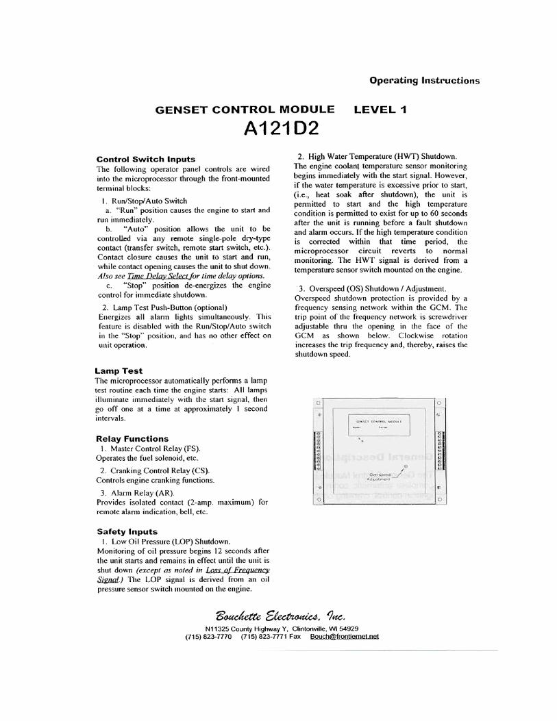
procedures before operating generator system. ENGINE CONTROL MODULE The Engine Control Module (E.C.M.) is a microprocessor based module that monitors the control and safety inputs and provides all the required START and STOP functions automatically. The following front panel controls and instruments are wired into the microprocessor through the E.C.M. terminal blocks: 1. RUN / OFF / AUTO SWITCH
A. "RUN" - run position causes the generator set to start and run immediately.
B. "AUTO" - auto position allows unit to be controlled via any remote single-pole "dry" contact (transfer switch, etc.). Contact closure causes the unit to start and run, while contact opening causes
unit to shut down after a preset cool down period. C. "OFF" - unit operation is terminated.
2. LAMP TEST A. Push button energizes all alarm lights simultaneously. This feature is disabled with the Run / stop / auto switch in the "stop" position and has no other effect on unit operation. SAFETY INPUTS
1. LOW OIL PRESSURE SHUT-DOWN (LOP)
Monitoring of oil pressure begins for a preset time after unit starts and remains in effect until unit is shut down (except as noted in "loss of frequency input". The LOP signal is derived from an oil pressure switch gauge mounted on the control panel.
2. HIGH TEMPERATURE SHUTDOWN (HT)
The engine temperature monitoring begins immediately with the start signal. However, if engine temperature is excessive prior to start (i.e. heat soak after shutdown), the unit is permitted to start. The High temperature condition is permitted to exist for up to 60 seconds after the unit is running before shutdown when alarm occurs. If the excessive temperature condition is corrected within that time period, the HT circuit reverts to normal monitoring. The HT signal is derived from a monitoring device located on the prime mover.
3. OVERSPEED ADJUSTMENT (OS) - OVER FREQUENCY
Overspeed protection is provided by a frequency sensing network within the
22

controller. The trip point of the frequency network is adjustable via a rheostat located on the top of the controller at the right hand side. Clockwise (CW) rotation increases the trip frequency and, thereby, raises the shutdown speed. CRANKING CONTROL 1. OVERCRANK PROTECTION This feature provides a preset second crank cycle. Failure of the engine to start by the end of the crank period results in an "overcrank" shutdown and alarm indication. 2. CRANKING DISCONNECT ADJUSTMENT (CDS ADJUSTMENT) The cranking disconnect signal is obtained by a frequency network within the controller. The trip point of the frequency network is not adjustable. LOSS OF FREQUENCY Internal protection against loss of frequency input to the cranking disconnect circuit is programmed in after the unit has started normally. In the event the frequency goes to zero (engine runs out of fuel, frequency signal source fails, etc.) the LOP shutdown circuit is bypassed and a 12-second wait period is initiated. If frequency returns within this time period, LOP monitoring resumes and operation continues normally. If frequency has not returned at the end of this time period, the engine oil pressure status is observed to determine whether the engine is actually running or stopped. If the engine has stopped (i.e. air in fuel, etc.) the cranking cycle will begin in an effort to restart the engine. If the engine has not stopped (loss of input signal, etc.) the unit is shut down with an "overcrank" indication and alarm.
"Overcrank" indication
can mean a loss of crank-disconnect signal during the previous run period. Attempting to restart the engine with no crank- disconnect can destroy the starter motor, which can cause serious personal injury. This is of particular note since the tendency is to pursue only cranking and start related faults. The cranking disconnect signal source is a key component in this system and must be checked out thoroughly whenever an "overcrank" shutdown occurs.
The controller does not Provide protection against
loss of signal during startup. A shutdown with alarm, due to any of the above conditions, will prevent any subsequent operation of the generator set. The run- stop-auto selector switch on the control panel must be momentarily placed in the "stop" position to reset these functions. If a dead battery is suspected, remove controller fuse, Replace with new battery and attempt starting. Damage to engine control may result from jump-starting.
23

THIS PAGE INTENTIONALLY LEFT BLANK
24

ENGINE OPERATORS MANUAL
25


ENGINE CONTROLS, ACCESSORIES, AND REMOTE CONNECTION DIAGRAMS:
PARTS LIST
AC GENERATOR ACCESSORIES AND
LOAD CONNECTION DIAGRAMS
ENGINE CONTROL DEVICE ENGINE MONITORING DEVICES
BALDOR GENERATORS WARRANTY ENGINE WARRANTY
MAINTENANCE RECORD
27

THIS PAGE INTENTIONALLY LEFT BLANK
28

AE25-E-NG PARTS LIST SPEC #: 10.93025
PART NUMBER DESCRIPTION QTY 10.93025 GEN SET AE25 1 PHASE 120/240V NATURAL GAS, ENCLOSED QTY 1 EH0373A04 ASSEMBLY, ENCLOSURE QTY 1 EH0278B72 ASSEMBLY, DOOR QTY 2 EH0278B02C1B PANEL, RIGHT DOOR QTY 1 EH0278B03C1B PANEL, LEFT DOOR QTY 1 HB2413A00 LATCH, PANEL, TOOL ACTIVATED QTY 2 HW2409A03 HINGE, SMALL DOORS, TS25-80 QTY 4 07XN1032Y12 SCREW, 10-32 X ¾ PHRH YZ QTY 8 HW1000A10 #10 FLAT WASHER (SAE) QTY 8 XY1032Y02N NUT, 10-32 LOCK W/ NYLOCK YZ QTY 8 EH0278A78C1B HOOD, AE25LS QTY 1 EH0386A02 ASSEMBLY, FRONT SECTION QTY 1 EH0278A79C1B POST, RT FRONT CORNER, AE25LS QTY 1 EH0278A80C1B POST, LT FRONT CORNER, AE25LS QTY 1 EH0278A83C1B PANEL , FRONT ACCESS, AE25LS QTY 1 EH0278A85C1B PANEL , RADIATOR BULKHEAD, AE25LS QTY 1 89XN2520Y12T BOLT, ¼ - 20 X ¾ THPH (YZ) W/ PAT QTY 20 HW5122A00 WASHER, NYLON ¼" QTY 20 EH0386A03 ASSEMBLY, REAR SECTION QTY 1 EH0278A84C1B PANEL, REAR ACCESS, AE25 QTY 1 EH0278A81C1B POST, RT REAR CORNER, AE25 QTY 1 EH0278A82C1B POST, LT REAR CORNER, AE25 QTY 1 EH0278A88C1B DUCT, LEFT AIR INTAKE, AE25LS QTY 1 EH0278B01C1B DUCT, RIGHT AIR INTAKE, AE25LS QTY 1 EH0278A88C1B DUCT, REAR ACCESS AIR INTAKE QTY 1 89XN2520Y12T BOLT, ¼ - 20 X ¾ THPH (YZ) W/PAT QTY 30 HW5122A00 WASHER, NYLON ¼" QTY 30 BA0232A03L2B ASSEMBLY, BASE WELDMENT, AE25LS QTY 1 EA5014A01 ASSEMBLY, ENGINE FORD, LRG 425 2.5 LITER QTY 1 GS0091A00 GASKET, FOR 710.00100 QTY 1 SE0052A00 ENGINE SOLENOID, LO PRESSURE QTY 1 EA0000A02 REGULATOR, LP/NAT GAS, LSG875, IMPCO53 QTY 1 HB6163A05L2B BRACKET, BATTERY TIE- DOWN, AE25 QTY 1 RM1088A11 ISOLATOR #51507-2 QTY 4 EA0006A08 RADIATOR RS-4026 QTY 1 FN0027A00 FAN, RADIATOR, AE25, 18/10/10/3HR/PAG/40A QTY 1 HB2002A07 SPACER, FAN QTY 1 EA0008A10 MUFFLER, DONALDSON QTY 1 EA0039A05 BLANKET, MUFFLER QTY 1 EA0039A06 BLANKET, EXHAUST PIPE QTY 1 TA0000A07 TANK, COOLANT RECOVERY QTY 1 HB6077A00 BRACKET, COOLANT RECOVERY TANK QTY 1 TA0002A07 CAP, COOLANT RECOVERY TANK QTY 1 EA0023A08 TAIL PIPE, "J" QTY 1 EA0001A01 SENDER, WATER TEMP, #02022-00 QTY 1 HB6007A00 BLOCK, REMOTE OIL PRESSURE SENDER QTY 1 EA0001A02 SENDER, OIL PRESSURE, ESP-100 QTY 1 EA0007A05 ASSEMBLY, MAGNETIC PICK-UP QTY 1 EA0010A02 CHARGER, BATTERY, 12V, 6 AMP QTY 1
29

PART NUMBER DESCRIPTION QTY EH0426A03 CIRCUIT BREAKER ASSEMBLY QTY 1 BE0406A00 ENCLOSURE, BREAKER QTY 1 CK0070A59 BREAKER, C-H, FG3125, W/O SHUNT TRIP QTY 1 BE0412A00 CONTROL BOX, AE25 QTY 1 EM0045A01 CONTROLLER, ENGINE, MEMORY 09, 132 TOOTH AE25 QTY 1 EM0027A01 REGULATOR, VOLTAGE - AVC63-2.0 QTY 1 EM0039A02 CONTROLLER, LRG423 FOR FORD 2.5 LITER ENGINE QTY 1 SP9094 SWITCH, DPDT 0121 0002 MCGILL QTY 1 SP9113 SWITCH, LP/NATURAL GAS QTY 1 EM0008A01 PANEL, INDICATOR QTY 1 WD3203A00 GAUGE, PRESSURE, EGS21P100-12 QTY 1 WD3204A00 GAUGE, TEMP, EGS21T250-12 QTY 1 WD3201A00 METER, ETM, 20001-16, 120V, 60HZ QTY 1 FU0066A00 FUSE BUSS, MTH-5 QTY 1 FU0066A07 FUSE, BUSS, ¼ X 1 ¼, AGC 15 QTY 1 FU0064A00 FUSE HOLDER, BUSSMAN HKP-HH QTY 2 EH0429A01 GENERATOR ASSEMBLY QTY 1 62SA0017A00L2B ASSEMBLY, STATOR W/ SHELL QTY 1 62EX5002A02 ASSY EXCITER FIELD, 2.0, AE25 QTY 1 62EP3200A02M BEARING BRACKET QTY 1 62RA0025A00 ROTOR, 25, 1800, SAE QTY 1 DI0177A00 RECTIFIER, 4 TERMINAL BRIDGE QTY 2 62FN2000A02 FAN, COOLING, 10.125" O.D. QTY 1 HB2011A10 HUB, COUPLING QTY 1 LB0100A22 DECAL, BALDOR AUTO EMERGENCY 20" QTY 1 LB0100A02 DECAL, BALDOR AUTO EMERGENCY 12" QTY 1 LB0100A03 DECAL, BALDOR AUTO EMERGENCY 39" SPLIT QTY 2 LB0094A11 DECAL, DANGER - HIGH VOLTAGE QTY 1 LB0094A30 DECAL, WARNING, AUTO START QTY 2 LB0095A07 PLACARD, "LINE" QTY 1 LB0095A08 PLACARD, "LOAD" QTY 1 LB0095A15 PLACARD, "NEUTRAL" QTY 1 LB0095A16 PLACARD, "L1" QTY 1 LB0095A17 PLACARD, "L2" QTY 1 LB0095A42 PLACARD, "REMOTE START" QTY 1 LB0095A51 PLACARD, "AC CONNECTION" QTY 1 LB0094A36 PLACARD, "DANGER, HOT" QTY 1 LB0095A37 PLACARD, "GROUND" QTY 1
DIAGRAMS PERTAINING TO THE AE25-E ARE AS FOLLOWS: WE0026D BW0155D BW0042D WE0027D (WIRING CHART)
BW0041D BW0049D BW0048D (WIRING CHART)
30


THIS PAGE INTENTIONALLY LEFT BLANK
38

BOUCHETTE A121G3 CONTROLLER (VENDOR INFO)
39


42

BALDOR GENERATORS OWNER WARRANTY POLICY
Effective November 1, 2001
WARRANTY PERIOD
Generator Series Parts & Labor* PARTS ONLY
Premier Pow’R Products 1 Year 3 Years
Diesel Pow’R Products 1 Year 3 Years
Powerchief Pow’R Products 1 Year 3 Years
Standby Systems 3600 R.P.M.
(AE)
1 Year Or
1000 Hours Whichever Comes First
3 Years Or
1,000 hours
Standby Systems 1800 R.P.M.
(AE, DLC,GLC, IDLC)
1 Year Or
3000 Hours Whichever Comes First
2 Years Or
3,000 hours
Switchables (TS)
1 Year Or
3000 Hours Whichever Comes First
3 Years Or
3,000 hours *For products covered under the labor coverage, travel expenses will be allowed up to 7 hours straight labor or 300 miles, which ever occurs first and only applies to permanently wired and mounted products (AE, DLC, IDLC, models).
NO WARRANTY REGISTRATION CARD IS NECESSARY TO OBTAIN WARRANTY ON BALDOR GENERATORS.
YOU MUST SAVE THE PURCHASE RECEIPT. A PROOF OF PURCHASE DATE, SERIAL NUMBER AND MODEL NUMBER WILL BE REQUIRED FOR ALL WARRANTY REPAIR WORK.
LIMITED WARRANTY “Baldor Generators will repair or replace, free of charge, any part, or parts of the generator of their manufacture that aredefective in material or workmanship or both. Transportation charges on parts submitted for repair or replacement shall beprepaid and added to the claim if failure is determined to be warrantable under this policy. Transportation costs on partssubmitted are only covered to the nearest authorized Baldor Generator repair facility, the factory (if requested) and at no timeincludes air, sea or specialty costs unless pre-authorized. This warranty is effective for the time periods and subject to theconditions provided for in this policy to the original owner and is not transferable. For warranty service contact BaldorGenerators’ Customer Service Department at (920) 236-4200. THERE IS NO OTHER EXPRESS WARRANTY. IMPLIEDWARRANTIES, INCLUDING THOSE OF MERCHANTABILITY AND FITNESS FOR A PARTICULAR PURPOSE, ARE LIMITEDTO ONE YEAR FROM PURCHASE OR TO THE EXTENT PERMITTED BY LAW. ANY AND ALL OTHER IMPLIEDWARRANTIES ARE EXCLUDED. LIABILITY FOR CONSEQUENTIAL DAMAGES UNDER ANY AND ALL WARRANTIES AREEXCLUDED TO THE EXTENT EXCLUSION IS PERMITTED BY LAW. Some states do not allow limitations on how long animplied warranty lasts and some states do not allow the exclusion or limitation of incidental or consequential damages, so theabove limitation and exclusion may not apply to you. This warranty gives you specific legal rights and you may also have otherrights which vary from state to state.”
Baldor Generators

Owner’s Responsibilities: The owner is obligated to operate and maintain the generator in accordance with the recommendations published by Baldor Generators in the Operator’s Manual for the generator. The owner is responsible for the costs associated with maintenance and any adjustments, which may be required. All claims must be brought to the attention of Baldor Generators within 30 days after discovery that the generator fails to meet this warranty. The owner is responsible for payment of any of the following expenses that might be incurred as a result of a failure under the terms of this warranty: 1. Rental equipment used to replace the equipment being repaired. 2. Telephone or other communication expenses. 3. Living and travel expenses of persons performing service, except as specifically
included within the terms of a specific warranty. 4. The premium costs for overtime labor requested by the owner. 5. All parts transportation costs. Limitations: Baldor Generators is not responsible for the repair of generators required because of normal wear, accident, misuse, abuse, improper installation, lack of maintenance, unauthorized modifications or improper storage. Normal Wear: This warranty will not cover repair where normal use has exhausted the life of a part or generator. It should be remembered that the service life of any generator is dependent on the care it receives and the conditions under which it has to operate. Some applications are very often used in dusty or dirty conditions, which can cause what appears to be excessive wear. Such wear, when caused by dirt, dust, grit or other abrasive material, which has entered the generator because of improper maintenance, is not covered by Warranty. No person is authorized to give any other warranties or to assume any other liabilities on Baldor Generators’ behalf unless made or assumed in writing by an officer of Baldor Generators and no person is authorized to give any warranties or assume any other liability on behalf of the seller unless made or assumed in writing by seller. Major components, such as engines, used in Baldor Generators’ generator sets that are not manufactured by Baldor Generators are specifically excluded from Baldor Generators coverage and are covered separately by their respective manufacturers. Warranty terms and policies of excluded products are included with the owners’ information package supplied with each product.
3815 Oregon Street • Oshkosh, Wisconsin 54902 Phone: (920) 236-4200 • 800-872-7697 • Fax: (920) 236-4219
www.baldor.com 44

MAINTENANCE SERVICE RECORD DATE METERED HOURS SERVICE PERFORMED
45

THIS PAGE INTENTIONALLY LEFT BLANK
46

!! WARNING !!
CALIFORNIA PROPOSITION 65 WARNING Engine exhaust from this product contains chemicals known
to the state of California to cause cancer, birth defects, and other reproductive harm.
!! WARNING !!
CALIFORNIA PROPOSITION 65 WARNING Diesel engine exhaust and some constituents are known to the state of California to cause cancer, birth defects, and other reproductive harm.
47

Service is just a phone call away:
800-872-7697
www.baldor.com/products/generators.asp
3815 Oregon Street Oshkosh WI 54902
Phone: (920) 236-4200 Fax: (920) 236-4219
48