OPERATOR'S MANUAL LAND LEVELER - John Deeremanuals.deere.com/cceomview/5DDP00211_19/Output/5... ·...
34
LL14_5DDP00211_3_8_10 LAND LEVELER OPERATOR'S MANUAL LL1410 LL1412 LL1414 LL1416
Transcript of OPERATOR'S MANUAL LAND LEVELER - John Deeremanuals.deere.com/cceomview/5DDP00211_19/Output/5... ·...

LL14_5DDP00211_3_8_10
LAND LEVELERO P E R A T O R ' S M A N U A L
L L 1 4 1 0
L L 1 4 1 2
L L 1 4 1 4
L L 1 4 1 6
Introduction ii
TO THE DEALER:
Assembly and proper installation of this product is the responsibility of the Frontier dealer. Read manu-al instructions and safety rules. Make sure all items on the Dealer’s Pre-Delivery and Delivery Check Lists in the Owner’s/Operator’s Manual are completed before releasing equipment to the owner.
The dealer must complete the Warranty Registration located on the Frontier website.
TO THE OWNER:
Read this manual before operating your Frontier equipment. The information presented will prepare you to do a better and safer job. Keep this manual handy for ready reference. Require all operators to read this manual carefully and become acquainted with all the adjustment and operating procedures before attempting to operate. Replacement manuals can be obtained from your Frontier dealer.
The equipment you have purchased has been carefully engineered and manufactured to provide dependable and satisfactory use. Like all mechanical products, it will require cleaning and upkeep. Lubricate the unit as specified. Observe all safety information in this manual and safety decals on the equipment.
For service, your authorized Frontier dealer has trained mechanics, genuine Frontier service parts, and the necessary tools and equipment to handle all your needs.
Use only genuine Frontier service parts. Substitute parts will void the warranty and may not meet stan-dards required for safe and satisfactory operation. Record the model number and serial number of your equipment in the spaces provided:
Model:____________________________________ Date of Purchase:_________________
Serial Number: (see Safety Decal section for location)_______________________________
Provide this information to your dealer to obtain correct repair parts.
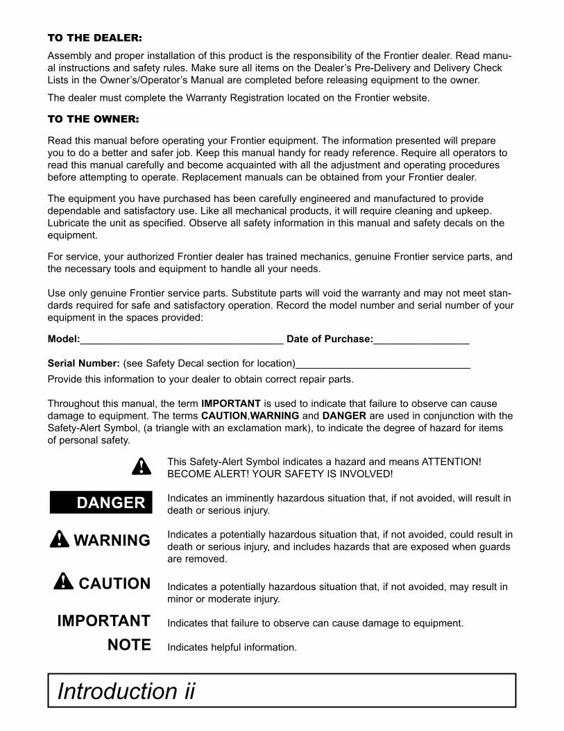
Throughout this manual, the term IMPORTANT is used to indicate that failure to observe can cause damage to equipment. The terms CAUTION,WARNING and DANGER are used in conjunction with the Safety-Alert Symbol, (a triangle with an exclamation mark), to indicate the degree of hazard for items of personal safety.
DANGER
WARNING
CAUTION
IMPORTANT
NOTE
This Safety-Alert Symbol indicates a hazard and means ATTENTION!BECOME ALERT! YOUR SAFETY IS INVOLVED!
Indicates an imminently hazardous situation that, if not avoided, will result in death or serious injury.
Indicates a potentially hazardous situation that, if not avoided, could result in death or serious injury, and includes hazards that are exposed when guards are removed.
Indicates a potentially hazardous situation that, if not avoided, may result in minor or moderate injury.
Indicates that failure to observe can cause damage to equipment.
Indicates helpful information.
The purpose of this manual is to assist you in operating and maintaining your leveling scraper. Read it carefully. It furnishes infor-mation and instructions that will help you achieve years of dependable perfor-mance.
These instructions have been compiled from field experience and engineering data. Some information may be general in nature, due to unknown and varying oper-ating conditions. However, through expe-rience and these instructions, you should be able to develop procedures suitable to
your particular situation.
The illustrations and data used in this manual were current at the time of print-ing. However, due to possible inline pro-duction changes, your machine may vary slightly in detail. We reserve the right to redesign and change the machines as may be necessary without notification.
Throughout this manual, references are made to right and left direction. These are determined by standing behind the tractor facing the direction of forward travel.
GENERAL INFORMATION
Table of Contents
TABLE OF CONTENTS
INTRODUCTION . . . . . . . . . . . . . . . . . . . . . . . . . . . . . . . . . . . . . . . . . . . . . . ii
SPECIFICATIONS / GENERAL INFORMATION . . . . . . . . . . . . . . . . . . . . . . . . . . . . . . . 1, 2
SAFETY DECALS . . . . . . . . . . . . . . . . . . . . . . . . . . . . . . . . . . . . . . . . . . . . . . . 3, 4
SAFETY RULES . . . . . . . . . . . . . . . . . . . . . . . . . . . . . . . . . . . . . . . . . . . . . . 5 - 7
DEALER INSTRUCTIONS . . . . . . . . . . . . . . . . . . . . . . . . . . . . . . . . . . . . . . . . . . . . 8
OPERATION . . . . . . . . . . . . . . . . . . . . . . . . . . . . . . . . . . . . . . . . . . . . . . . . . . . . . . . . . . 9 - 14
OWNERS RESPONSIBILTY . . . . . . . . . . . . . . . . . . . . . . . . . . . . . . . . . . . . . . . . . . . 10, 11
SET UP . . . . . . . . . . . . . . . . . . . . . . . . . . . . . . . . . . . . . . . . . . . . . . . . . . . . . . . . . . 11, 12
MAINTENANCE . . . . . . . . . . . . . . . . . . . . . . . . . . . . . . . . . . . . . . . . . . . . . . . . . 12, 13
LUBRICATION . . . . . . . . . . . . . . . . . . . . . . . . . . . . . . . . . . . . . . . . . . . . . . . . . . . . . . 13
HYDRAULICS . . . . . . . . . . . . . . . . . . . . . . . . . . . . . . . . . . . . . . . . . . . . . . . . . . . . . 14
PARTS CATALOG . . . . . . . . . . . . . . . . . . . . . . . . . . . . . . . . . . . . . . . . . . . . . . . . . 15 - 19
OPTIONAL EQUIPMENT . . . . . . . . . . . . . . . . . . . . . . . . . . . . . . . . . . . . . . . . . . . . . . . . 20 - 28
BOLT AND BOLT TORQUE CHART . . . . . . . . . . . . . . . . . . . . . . . . . . . . . . . . . . 29
NOTES . . . . . . . . . . . . . . . . . . . . . . . . . . . . . . . . . . . . . . . . . . . . . . . . . . . . 30

1 Specifications
LL14 SERIES BASE UNITSPECIFICATIONS
Model LL1410 LL1412 LL1414 LL1416
Tractor HP 140-535 140-535 180-535 180-535
Working Width 10 Feet 12 Feet 14 Feet 16 Feet
Machine Width 124.5 Inches 148.5 Inches 172.5 Inches 196.5 Inches
Machine Length 17.5 Feet 17.5 Feet 17.5 Feet 17.5 Feet
Machine Height 52 Inches 52 Inches 52 Inches 52 Inches
Operating Weight 6260 lbs. 7500 lbs. 8750 lbs 10000 lbs.
Hitch Type Drawn Drawn Drawn Drawn
Wheels 10 x 16 10 x 16 10 x 16 10 x 16
Tire 12.5L x 16 12.5L x 16 12.5L x 16 12.5L x 16
Cutting Edge Standard 8" Tall, 5/8 Thick Grading Blade
Standard 8" Tall, 5/8 Thick Grading Blade
Standard 8" Tall, 5/8 Thick Grading Blade
Standard 8" Tall, 5/8 Thick Grading Blade
Moldboard Thickness 7/8 Inch 7/8 Inch 7/8 Inch 7/8 Inch
End Plate Thickness 5/8 Inch 5/8 Inch 5/8 Inch 5/8 Inch
Hydraulic Cylinders Standard Standard Standard Standard
Hydraulic Cylinders (#) 2 Phasing 2 Phasing 2 Phasing 2 Phasing
Cylinder Size 4.75, 4.50 Bore 4.75, 4.50 Bore 4.75, 4.50 Bore 4.75, 4.50 Bore
Cylinder Stroke Length 10 Inches 10 Inches 10 Inches 10 Inches
Rear Weight Bracket Optional Optional Optional Optional
Max. # John Deere 100 lb. Suit Case Weights
3200 3200 4200 4600
Max. Weight Per Inch of Blade
125 lb. 125 lb. 125 lb. 125 lb.
Jack Stand Standard Standard Standard Standard
Safety Chains Standard Standard Standard Standard
Duty Construction Construction Construction Construction
Warranty 6 Months Warranty 6 Months Warranty 6 Months Warranty 6 Months Warranty
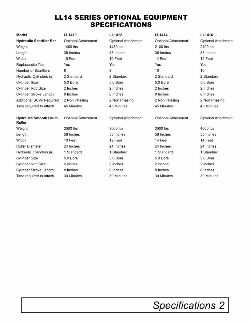
LL14 SERIES OPTIONAL EQUIPMENTSPECIFICATIONS
Specifications 2
Model LL1410 LL1412 LL1414 LL1416
Hydraulic Scarifier Bar Optional Attachment Optional Attachment Optional Attachment Optional Attachment
Weight 1480 lbs 1480 lbs 2100 lbs 2100 lbs
Length 38 Inches 38 Inches 38 Inches 38 Inches
Width 10 Feet 10 Feet 14 Feet 14 Feet
Replaceable Tips Yes Yes Yes Yes
Number of Scarifiers 8 8 10 10
Hydraulic Cylinders (#) 2 Standard 2 Standard 2 Standard 2 Standard
Cylinder Size 5.0 Bore 5.0 Bore 5.0 Bore 5.0 Bore
Cylinder Rod Size 2 Inches 2 Inches 2 Inches 2 Inches
Cylinder Stroke Length 8 Inches 8 Inches 8 Inches 8 Inches
Additional SCVs Required 2 Non Phasing 2 Non Phasing 2 Non Phasing 2 Non Phasing
Time required to attach 45 Minutes 45 Minutes 45 Minutes 45 Minutes
Hydraulic Smooth Drum Roller
Optional Attachment Optional Attachment Optional Attachment Optional Attachment
Weight 2500 lbs 3000 lbs 3500 lbs 4000 lbs
Length 58 Inches 58 Inches 58 Inches 58 Inches
Width 10 Feet 12 Feet 14 Feet 14 Feet
Roller Diameter 24 Inches 24 Inches 24 Inches 24 Inches
Hydraulic Cylinders (#) 1 Standard 1 Standard 1 Standard 1 Standard
Cylinder Size 5.0 Bore 5.0 Bore 5.0 Bore 5.0 Bore
Cylinder Rod Size 2 inches 2 inches 2 inches 2 inches
Cylinder Stroke Length 8 Inches 8 Inches 8 Inches 8 Inches
Time required to attach 30 Minutes 30 Minutes 30 Minutes 30 Minutes
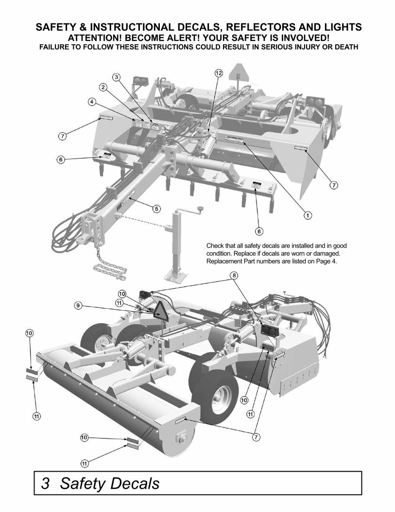
SAFETY & INSTRUCTIONAL DECALS, REFLECTORS AND LIGHTSATTENTION! BECOME ALERT! YOUR SAFETY IS INVOLVED!
FAILURE TO FOLLOW THESE INSTRUCTIONS COULD RESULT IN SERIOUS INJURY OR DEATH
Check that all safety decals are installed and in good condition. Replace if decals are worn or damaged. Replacement Part numbers are listed on Page 4.
3 Safety Decals
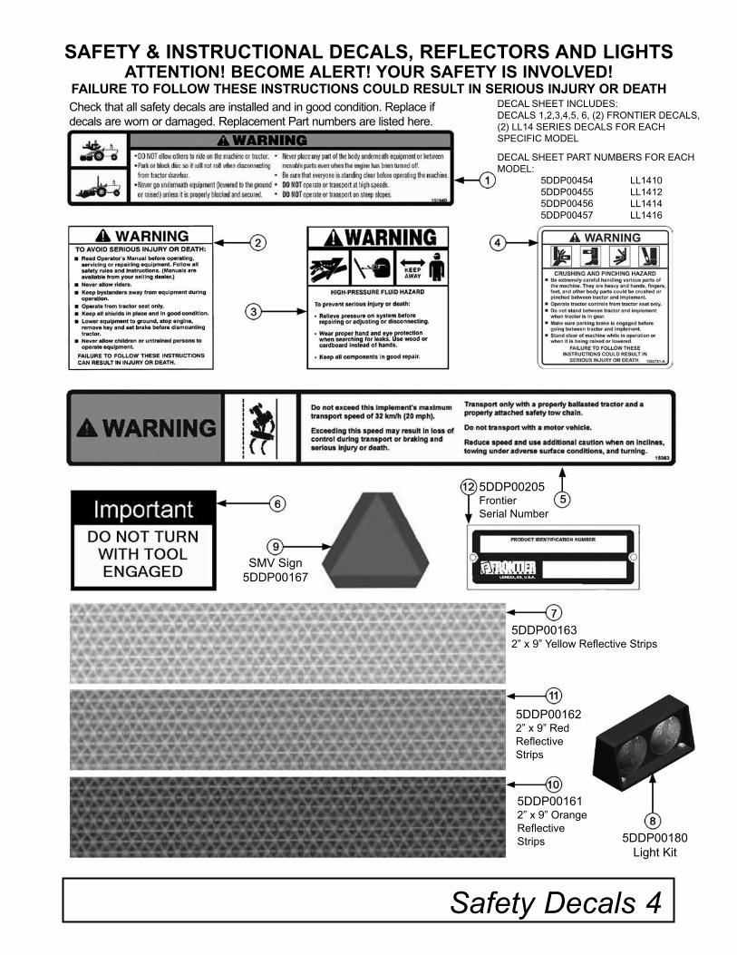
Check that all safety decals are installed and in good condition. Replace if decals are worn or damaged. Replacement Part numbers are listed here.
Safety Decals 4
SAFETY & INSTRUCTIONAL DECALS, REFLECTORS AND LIGHTSATTENTION! BECOME ALERT! YOUR SAFETY IS INVOLVED!
FAILURE TO FOLLOW THESE INSTRUCTIONS COULD RESULT IN SERIOUS INJURY OR DEATH
SMV Sign5DDP00167
5DDP00205FrontierSerial Number
5DDP001632” x 9” Yellow Reflective Strips
5DDP001622” x 9” RedReflectiveStrips
5DDP001612” x 9” OrangeReflectiveStrips 5DDP00180
Light Kit
DECAL SHEET INCLUDES:DECALS 1,2,3,4,5, 6, (2) FRONTIER DECALS,(2) LL14 SERIES DECALS FOR EACH SPECIFIC MODEL
DECAL SHEET PART NUMBERS FOR EACH MODEL: 5DDP00454 LL1410 5DDP00455 LL1412 5DDP00456 LL1414 5DDP00457 LL1416
5 Safety Rules
Safety is a primary concern in the design and manufacture of our products. Unfortunately, our efforts to provide safe equipment can be wiped out by an operator’s single careless act.
In addition to the design and configuration of equipment, hazard control and accident preven-tion are dependent upon the awareness, con-cern, judgement, and proper training of person-nel involved in the operation, transport, mainte-nance and storage of equipment.
It has been said “The best safety device is an informed, careful operator.” We ask you to be that kind of operator.
TRAINING
• Safety instructions are important! Read all attachment and power unit manuals; follow all safety rules and safety decal information. (Replacement manuals are available from sell-ing dealer.) Failure to follow instructions or safety rules can result in serious injury or death.
• If you do not understand any part of this manu-al and need assistance, see your dealer.
• Operators must be instructed in and be capa-ble of the safe operation of the equipment, its attachments, and all controls. Do not allow any-one to operate this equipment without proper instructions.
• Never allow children or untrained persons to operate equipment.
• Train all new personnel and review instruction’s frequently with existing workers. A person who has not read and understood all operating and safety instructions is not qualified to operate the machine. An untrained operator exposes himself and bystanders to possible serious injury or death.
PREPARATION
• Always wear relatively tight and belted clothing to
avoid getting caught in moving parts. Wear sturdy, rough-soled work shoes and protective equip-ment for eyes, hair, hands, hearing, and head; and respirator or filter mask where appropri-ate.
• Make sure attachment is properly secured, adjusted, and in good operating condition.
• Power unit must be equipped with ROPS or ROPS cab and seat belt. Keep seat belt securely fastened. Falling off power unit can result in death from being run over or crushed. Keep foldable ROPS system in “locked up” position at all times.
• A minimum 20% of tractor and equipment weight must be on the tractor front wheels when attachments are in transport position. Without this weight, the tractor could tip over, causing personal injury or death. The weight may be attained with a loader, front wheel weights, bal-last in tires or front tractor weights. Weigh the tractor and equipment. Do not estimate.
TRANSPORTATION
• Always comply with all state and local laws governing highway safety and lighting and marking requirements.
• Keep away from overhead power lines. Serious injury or death may result. Know the transport height and width of your machine.
• Never allow riders on power unit or attach-ment.
• Do not operate or transport on steep slopes.
• Use extreme care and reduce ground speed on slopes and rough terrain.
• Prevent collisions between other road users, slow moving tractors with attachments or towed equipment, and self-propelled machines on public roads. Frequently check for traffic from the rear, especially in turns, and use turn signal lights
• Power unit must be equipped with ROPS or ROPS cab and seat belt. Keep seat belt securely fastened. Falling off power unit can result in death from being run over or crushed. Keep foldable ROPS system in “locked up” position at all times.
• Never allow riders on power unit or attach-ment.
• Always sit in power unit seat when operating controls or starting engine. Securely fasten seat belt, place transmission in neutral, engage brake, and ensure all other controls are disen-gaged before starting power unit engine.
• Look down and to the rear and make sure area is clear before operating in reverse.
• Use extreme care when working close to fences, ditches, other obstructions, or on hillsides.
• Do not operate or transport on steep slopes.
• Do not stop, start, or change directions sud-denly on slopes. Always operate down slopes; never across the face.
• Use extreme care and reduce ground speed on slopes and rough terrain.
• Keep alert and watch the front, as well as, the rear when operating.
• Be careful to keep hands and feet clear of slid-ing parts and possible pinch points.
• Stop power unit and equipment immediately upon striking an obstruction. Engage brake, turn off engine, remove key, inspect, and repair any damage before resuming operation.
• Before leaving operator’s seat, put equipment on the ground. Engage brake, stop engine, remove key, and remove seat belt.
Safety Rules 6
• Do not operate or transport equipment while under the influence of alcohol or drugs. Consult your doctor about operating this machine while taking prescription medications.
OPERATION
• Never go underneath equipment (lowered to the ground or raised) unless it is properly blocked and secured.
•Never place any part of the body underneath equipment or between moveable parts even when the engine has been turned off. Hydraulic system leak down, hydraulic system failures, mechanical failures, or movement of control levers can cause equipment to drop or rotate unexpectedly and cause severe injury or death.
• Escaping fluid under pressure can penetrate the skin causing serious injury. Avoid the haz-ard by relieving pressure before disconnecting hydraulic or other lines. Tighten all connections before applying pressure. Search for leaks with a piece of cardboard.
• Protect hands and body from high pressure fluids. If an accident occurs, see a doctor imme-diately. Any fluid injected into the skin must be surgically removed within a few hours or gan-grene may result. Doctors unfamiliar with this type of injury should reference a knowledge-able medical source.
• Always comply with all state and local laws governing highway safety and lighting and marking requirements.
• Operate only in daylight or good artificial light.
• Keep bystanders away from equipment.
• Keep hands, feet, hair, and clothing away from equipment while engine is running. Stay clear of all moving parts.
7 Safety Rules
MAINTENANCE
• Always wear relatively tight and belted cloth-ing to avoid getting caught in moving parts. Wear sturdy, rough-soled work shoes and pro-tective equipment for eyes, hair, hands, hear-ing, and head; and respirator or filter mask where appropriate.
• Never go underneath equipment (lowered to the ground or raised) unless it is properly blocked and secured. Never place any part of the body underneath equipment or between moveable parts even when the engine has been turned off. Hydraulic system leak down, hydraulic system failures, mechanical failures, or movement of control levers can cause equip-ment to drop or rotate unexpectedly and cause severe injury or death.
• When performing maintenance or repairs make sure the equipment is in the lowered posi-tion and properly blocked and secured to pre-vent rolling. Failure to do so can cause serious injury or death.
• Make sure equipment is properly secured, adjusted, and in good operating condition.
• Before leaving operator’s seat, put equipment on the ground. Engage brake, stop engine, remove key, and remove seat belt.
• Never perform service or maintenance with engine running.
• Keep all persons away from operator control area while performing adjustments, service, or maintenance.
• Use tools appropriate to the work. Makeshift tools and procedures can create safety haz-ards.
• Use power tools only to loosen threaded parts and fasteners.
• For loosening and tightening hardware, use the correct size tools. DO NOT use U.S. mea-surement tools on metric fasteners or vice versa. Avoid bodily injury caused by slipping wrenches.
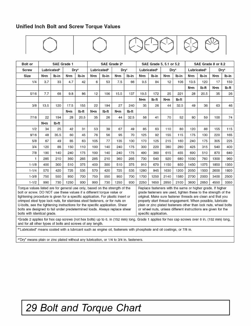
• Tighten all bolts, nuts, and screws to torque chart specifications(Refer to Bolt and Torque Chart on Page 29). Check that all cotter pins are installed securely to ensure equipment is in a safe condition before putting unit into ser-vice.
• Explosive separation of a tire and rim parts can cause serious injury or death.
• Do not attempt to mount a tire unless you have the proper equipment and experience to perform the job.
• Always maintain the correct tire pressure. Do not inflate the tires above the recommended pressure. Never weld or heat a wheel and tire assembly. The heat can cause an increase in air pressure resulting in a tire explosion. Welding can structurally weaken or deform the wheel.
• When inflating tires, use a clip-on chuck and extension hose long enough to allow you to stand to one side and NOT in front of or over the tire assembly. Use a safety cage if avail-able.
• Check wheels for low pressure, cuts, bubbles, damaged rims or missing lug bolts and nuts.
STORAGE
• Block equipment securely for storage.
• Keep children and bystanders away from stor-age area.
Dealer Instructions 8
Dealer’s Responsibility
Dealer Checklist
Inspect the equipment thoroughly after assem-bly to be certain it is set up properly before delivering it to the customer. The following check list is a reminder of points to inspect.
Check off each item if it is found satisfactory or after proper adjustment is made.
____ Check that all safety decals are installed and in good condition. Replace if damaged.
____ Check all bolts to be sure they are tight and torqued to proper specifications as per the chart on page 29.
____ Check that all cotter pins and safety pins are properly installed.
____It is important for the dealer to visually check and make sure all parts are in tact prior to delivery to customer.
____ Show customer the safe, proper proce-dures to be used when mounting, dismounting, and storing equipment.
____ Show customer how to make adjustments.
____ Present Operator’s Manual and request that customer and all operators read it before operating equipment. Point out the manual safety rules, explain their meanings and empha-size the increased safety hazards that exist when safety rules are not followed.
____ Point out the safety decals. Explain their meaning and the need to keep them in place and in good condition. Emphasize the increased safety hazards when instructions are not fol-lowed.
____ Explain to customer the potential crushing hazards of going underneath raised equipment. Instruct customer that service work does not require going underneath unit and never to do so.
____ Complete the Warranty Registrationlocated on the Frontier website.
DEALER INSTRUCTIONS
9 Operation
Safety is a primary concern in the design and manufacture of our products. Unfortunately, our efforts to provide safe equipment can be wiped out by an operator’s single careless act.
In addition to the design and configuration of equipment, hazard control and accident pre-vention are dependent upon the awareness, concern, judgement, and proper training of per-sonnel involved in the operation, transport, maintenance, and storage of equipment.
It has been said “The best safety device is an informed, careful operator.” We ask you to be that kind of operator.
The operator is responsible for the safe opera-tion of this equipment. The operator must be properly trained. Operators should be familiar with the equipment, the tractor, and all safety practices before starting operation. Read the safety rules and safety decals on pages 3-7.
Owner should check and tighten all hardware after the first hour of operation. The break in stage of your new land leveler can cause mini-mal loosening of hardware. Please see Bolt Torque Chart (Page 29) for proper torque infor-mation.
• Before starting engine sound horn on the power unit twice to warn people in the vicinity that operation is about to begin.
• Power unit must be equipped with ROPS or ROPS cab and seat belt. Keep seat belt securely fastened. Falling off power unit can result in death from being run over or crushed.Keep foldable ROPS systems in “locked up” position at all times.
• Never allow children or untrained persons to operate equipment.
Operation
WARNING
• Keep bystanders away from equipment.
• NEVER GO UNDERNEATH EQUIPMENT.Never place any part of the body underneath equipment or between moveable parts even when the engine has been turned off. Hydraulic system leak down, hydraulic system failures, mechanical failures, or movement of control levers can cause equipment to drop or rotate unexpectedly and cause severe injury or death.
• Service work does not require going under-neath.
• Read Operator's Manual for service instruc-tions or have service performed by a qualified dealer.
• Stop power unit and implement immediately upon striking an obstruction. Turn off engine, remove key, inspect, and repair any damage before resuming operation.
• Always wear relatively tight and belted cloth-ing to avoid entanglement in moving parts. Wear sturdy, rough-soled work shoes and pro-tective equipment for eyes, hair, hands, hear-ing, and head.
Owner/Operator Pre-Operation Checklist(Owner’s/Operator’s Responsibility)
____ Review and follow all safety rules and safety decal instructions on page 3 through page 7.____ Check that equipment is properly and securely attached to tractor.____ Check that all safety decals are installed and in good condition. Replace if damaged.____ Check that all hardware is properly installed and secured.____ Do not allow riders.____ Make sure tractor ROPS or ROPS CABand seat belt are in good condition. Keep seat belt securely fastened during operation.
Operation 10
Always shift to park, set brakes and shut off the tractor when dismounting the tractor.
Always maintain the correct tire pressure. Do not over inflate tires.
Inspect tires and wheels daily. Do not operate with low tire pressure, cuts, bubbles, damaged rims, or missing or loose lug bolts and nuts.
Carefully inspect tire and rim assembly after a flat or under inflated tire for damage to the rim or tire.
Use a clip on chuck and extension hose long enough to stand clear and to the side of the wheel assembly when inflating tires.
Never cut or weld near an inflated tire or rim assembly. Heat may cause an increase in pres-sure that may cause the tire to explode.
Do not attempt to mount a tire without proper equipment and experience to complete the job.
Hydraulic System
Always relieve pressure before disconnecting hydraulic and other lines. Avoid high pressure flu-ids. Escaping fluid under pressure can penetrate the skin causing serious injury.
Search for leaks with a piece of cardboard. Protect hands and body from high pressure fluids. If an accident occurs, see a doctor immediately. Any fluid injected into the skin must be removed within a few hours.
Avoid using heat near pressurized fluid lines. Heating can generate flammable spray, resulting in severe burns.
Hydraulic hoses can fail due to physical damage, kinks, age and exposure. Check hoses regularly. Replace damaged or worn hoses immediately. All hydraulic couplers must be clear of dirt and debris. Use protective caps on all fluid openings. Foreign debris can damage the hydraulic system.
Check that the tractor's hydraulic fluid level is full. Run land leveler through several complete cycles from full cut to full dump to remove any trapped air from hydraulic hoses and cylinders. Recheck
WARNING
Owner's Responsibility
Always use a safety chains when transporting. Provide only enough slack in the chain to allow turning.
Always use road locks to hold the land leveler in the raised position when transporting(Page 12, Ref. Fig. 4, 5).
Check wheel lug nuts on land leveler before and after transporting.
Do not transport land leveler in excess of 20 mph. Slow down when turning and transporting over rough ground or the land leveler may tip over. Travel at a reasonable and safe speed.
Never remove locking pins until hydraulic cylinders and lines are full of fluid and free of air.
Stand clear when raising or lowering the land lev-eler. Beware of pinching hazards especially at the cutter bar, side panels and wheel assembly of land leveler.
Never stand with feet under soil penetrating cutter bars and side panel areas. Always use blocking to prevent movement of land leveler when maintain-ing or repairing land leveler.
Never lubricate, adjust, service or adjust land lev-eler when moving.
Never modify this land leveler without conferring first with the equipment representative.
Always store with the cutter bar in the down, at rest, position.
Beware of overhead wires and narrow gates. Be aware of the land leveler's length, height and width.
Always use safety lockups when servicing or repairing land leveler. Engage brake, shut off trac-tor and remove the key before servicing or repair-ing land leveler.
Do not operate close to a body of water.
WARNING
WARNING
Owner's Responsibility(cont’d) tractor's hydraulic fluid level and refill with the land leveler in the fully raised position as needed. Refer to power units OM for additional details.
Clean up any spilled fluid immediately to prevent accidents and/or environmental damage.
Use leakproof containers when draining fluid. Do not use food and beverage containers that may mislead someone into drinking it. Dispose of flu-ids properly.
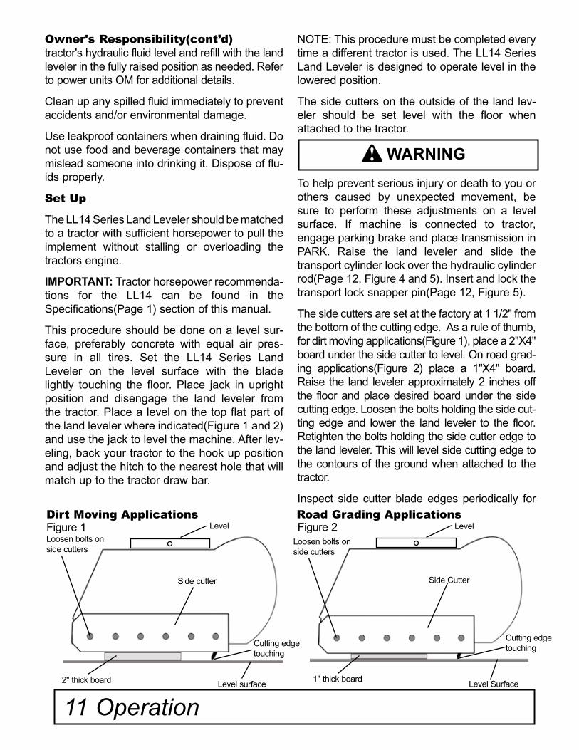
Set Up
The LL14 Series Land Leveler should be matched to a tractor with sufficient horsepower to pull the implement without stalling or overloading the tractors engine.
IMPORTANT: Tractor horsepower recommenda-tions for the LL14 can be found in the Specifications(Page 1) section of this manual.
This procedure should be done on a level sur-face, preferably concrete with equal air pres-sure in all tires. Set the LL14 Series Land Leveler on the level surface with the blade lightly touching the floor. Place jack in upright position and disengage the land leveler from the tractor. Place a level on the top flat part of the land leveler where indicated(Figure 1 and 2) and use the jack to level the machine. After lev-eling, back your tractor to the hook up position and adjust the hitch to the nearest hole that will match up to the tractor draw bar.
NOTE: This procedure must be completed every time a different tractor is used. The LL14 Series Land Leveler is designed to operate level in the lowered position.
The side cutters on the outside of the land lev-eler should be set level with the floor when attached to the tractor.
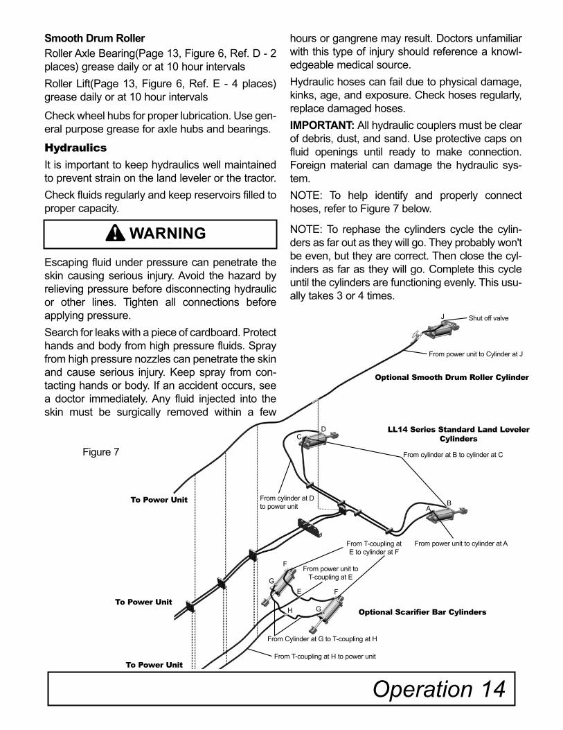
To help prevent serious injury or death to you or others caused by unexpected movement, be sure to perform these adjustments on a level surface. If machine is connected to tractor, engage parking brake and place transmission in PARK. Raise the land leveler and slide the transport cylinder lock over the hydraulic cylinder rod(Page 12, Figure 4 and 5). Insert and lock the transport lock snapper pin(Page 12, Figure 5).
The side cutters are set at the factory at 1 1/2" from the bottom of the cutting edge. As a rule of thumb, for dirt moving applications(Figure 1), place a 2"X4" board under the side cutter to level. On road grad-ing applications(Figure 2) place a 1"X4" board. Raise the land leveler approximately 2 inches off the floor and place desired board under the side cutting edge. Loosen the bolts holding the side cut-ting edge and lower the land leveler to the floor. Retighten the bolts holding the side cutter edge to the land leveler. This will level side cutting edge to the contours of the ground when attached to the tractor.
Inspect side cutter blade edges periodically for
11 Operation
Dirt Moving Applications Road Grading ApplicationsFigure 1
Level surface2" thick board
Loosen bolts onside cutters
Side cutter
Figure 2
Level Surface1" thick board
Side Cutter
Cutting edgetouching
Cutting edgetouching
Loosen bolts onside cutters
Level Level
WARNING
wear and damage. When damage or wear exsists switch the blade to its reversible cutting edge by loosening and removing the carriage bolts securing the blade to the moldboard end plate. Flip the blade and reinsert the carriage bolts, washers and tighten the nuts(Refer to the Bolt and Torque Chart on Page 29).
NOTE: It is important this procedure be done or you may experience excessive and unnecessary wear on the side cutters.
Side cutters are designed to contain debris. If the side cutters are showing uneven wear they are not set correctly
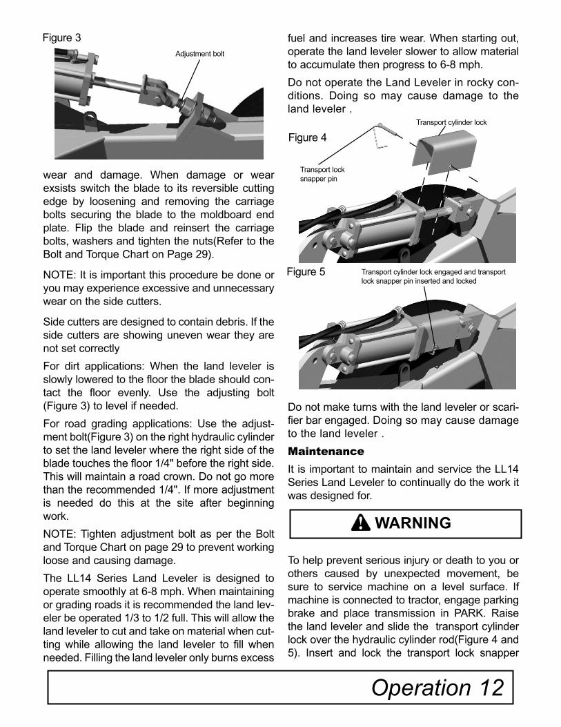
For dirt applications: When the land leveler is slowly lowered to the floor the blade should con-tact the floor evenly. Use the adjusting bolt (Figure 3) to level if needed.
For road grading applications: Use the adjust-ment bolt(Figure 3) on the right hydraulic cylinder to set the land leveler where the right side of the blade touches the floor 1/4" before the right side. This will maintain a road crown. Do not go more than the recommended 1/4". If more adjustment is needed do this at the site after beginning work.
NOTE: Tighten adjustment bolt as per the Bolt and Torque Chart on page 29 to prevent working loose and causing damage.
The LL14 Series Land Leveler is designed to operate smoothly at 6-8 mph. When maintaining or grading roads it is recommended the land lev-eler be operated 1/3 to 1/2 full. This will allow the land leveler to cut and take on material when cut-ting while allowing the land leveler to fill when needed. Filling the land leveler only burns excess
fuel and increases tire wear. When starting out, operate the land leveler slower to allow material to accumulate then progress to 6-8 mph.
Do not operate the Land Leveler in rocky con-ditions. Doing so may cause damage to the land leveler .
Do not make turns with the land leveler or scari-fier bar engaged. Doing so may cause damage to the land leveler .
Maintenance
It is important to maintain and service the LL14 Series Land Leveler to continually do the work it was designed for.
To help prevent serious injury or death to you or others caused by unexpected movement, be sure to service machine on a level surface. If machine is connected to tractor, engage parking brake and place transmission in PARK. Raise the land leveler and slide the transport cylinder lock over the hydraulic cylinder rod(Figure 4 and 5). Insert and lock the transport lock snapper
Operation 12
Figure 3Adjustment bolt
WARNING
Transport cylinder lock engaged and transport lock snapper pin inserted and locked
Figure 5
Transport lock snapper pin
Transport cylinder lock
Figure 4

13 Operation
Maintenance cont'd.pin(Page 12, Figure 5). Repeat this procedure for each cylinder on the land leveler and optional equipment attached to the land leveler. Shut off engine and remove key. If machine is detached from tractor block wheels and use safety stands to prevent movement.
Inspect side cutting edges periodically for wear and damage. Replace where necessary.
Maintain equal air pressure in all tires to prevent uneven cutting.
Check wheels for low pressure, cuts, bubbles, damaged rims or missing lug bolts and nuts. Replace as necessary.
Explosive separation of a tire and rim parts can cause serious injury or death. Do not attempt to mount a tire unless you have the proper equip-ment and experience to perform the job.
Always maintain the correct tire pressure. Do not inflate the tires above the recommended pres-sure.
Never weld or heat a wheel and tire assembly. The heat can cause an increase in air pressure result-ing in a tire explosion. Welding can structurally weaken or deform the wheel.
When inflating tires, use a clip-on chuck and extension hose long enough to allow you to stand to one side and NOT in front of or over the tire assembly.
Lubrication
It is important to maintain and service the LL14 Series Land Leveler to continually do the work it was designed for. Grease the land leveler at the following locations and intervals:
LL14 Series Land LevelerWheel Yoke Assembly(Figure 6, Ref. A - 4 places)grease daily or at 10 hour intervals.
Wheel Bogie Assembly(Figure 6, Ref. B - 4 places)grease daily or at 10 hour intervals
Optional Equipment Lubrication
Scarifier BarScarifier Lift(Figure 6, Ref. C - 2 places) grease daily or at 10 hour intervals
WARNING
Optional Scarifier BarLL14 Series Land Leveler Optional Smooth Drum Roller
A
A
B
B
C
C
D
D
Figure 6
E
E
From power unit to cylinder at A
From cylinder at B to cylinder at C
AB
CD LL14 Series Standard Land Leveler
Cylinders
Optional Smooth Drum Roller Cylinder
To Power Unit
From power unit to Cylinder at J
J Shut off valve
From power unit to T-coupling at E
E F
F
G
From cylinder at D to power unit
From T-coupling at E to cylinder at F
G
From Cylinder at G to T-coupling at H
H
From T-coupling at H to power unit
Optional Scarifier Bar Cylinders
To Power Unit
To Power Unit
Figure 7
Smooth Drum RollerRoller Axle Bearing(Page 13, Figure 6, Ref. D - 2 places) grease daily or at 10 hour intervals
Roller Lift(Page 13, Figure 6, Ref. E - 4 places) grease daily or at 10 hour intervals
Check wheel hubs for proper lubrication. Use gen-eral purpose grease for axle hubs and bearings.
Hydraulics
It is important to keep hydraulics well maintained to prevent strain on the land leveler or the tractor.
Check fluids regularly and keep reservoirs filled to proper capacity.
Escaping fluid under pressure can penetrate the skin causing serious injury. Avoid the hazard by relieving pressure before disconnecting hydraulic or other lines. Tighten all connections before applying pressure.
Search for leaks with a piece of cardboard. Protect hands and body from high pressure fluids. Spray from high pressure nozzles can penetrate the skin and cause serious injury. Keep spray from con-tacting hands or body. If an accident occurs, see a doctor immediately. Any fluid injected into the skin must be surgically removed within a few
Operation 14
WARNING
hours or gangrene may result. Doctors unfamiliar with this type of injury should reference a knowl-edgeable medical source.
Hydraulic hoses can fail due to physical damage, kinks, age, and exposure. Check hoses regularly, replace damaged hoses.
IMPORTANT: All hydraulic couplers must be clear of debris, dust, and sand. Use protective caps on fluid openings until ready to make connection. Foreign material can damage the hydraulic sys-tem.
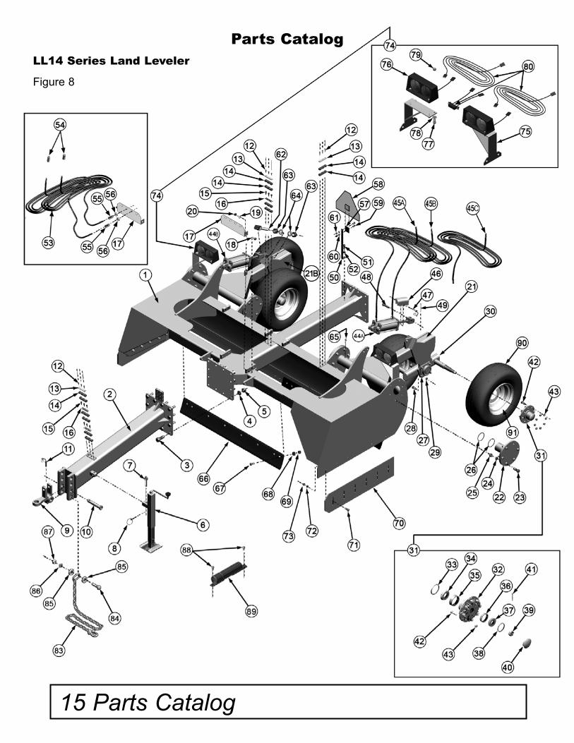
NOTE: To help identify and properly connect hoses, refer to Figure 7 below.
NOTE: To rephase the cylinders cycle the cylin-ders as far out as they will go. They probably won't be even, but they are correct. Then close the cyl-inders as far as they will go. Complete this cycle until the cylinders are functioning evenly. This usu-ally takes 3 or 4 times.
15 Parts Catalog
LL14 Series Land Leveler
Figure 8
Parts Catalog
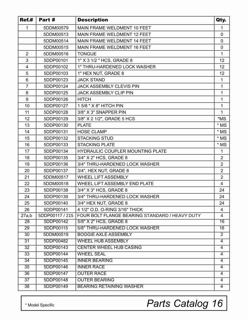
Ref.# Part # Description Qty.
1 5DDM00579 MAIN FRAME WELDMENT 10 FEET 1
5DDM00513 MAIN FRAME WELDMENT 12 FEET 0
5DDM00514 MAIN FRAME WELDMENT 14 FEET 0
5DDM00515 MAIN FRAME WELDMENT 16 FEET 0
2 5DDM00516 TONGUE 1
3 5DDP00101 1" X 3 1/2 " HCS, GRADE 8 12
4 5DDP00102 1" THRU-HARDENED LOCK WASHER 12
5 5DDP00103 1" HEX NUT, GRADE 8 12
6 5DDP00123 JACK STAND 1
7 5DDP00124 JACK ASSEMBLY CLEVIS PIN 1
8 5DDP00125 JACK ASSEMBLY CLIP PIN 1
9 5DDP00126 HITCH 1
10 5DDP00127 1 5/8 " X 8" HITCH PIN 1
11 5DDP00128 3/8" X 3" SNAPPER PIN 1
12 5DDP00129 3/8" X 2 1/2", GRADE 5 HCS *MS
13 5DDP00130 PLATE * MS
14 5DDP00131 HOSE CLAMP * MS
15 5DDP00132 STACKING STUD * MS
16 5DDP00133 STACKING PLATE * MS
17 5DDP00134 HYDRAULIC COUPLER MOUNTING PLATE 1
18 5DDP00135 3/4" X 2" HCS, GRADE 8 2
19 5DDP00136 3/4" THRU-HARDENED LOCK WASHER 2
20 5DDP00137 3/4", HEX NUT, GRADE 8 2
21 5DDM00517 WHEEL LIFT ASSEMBLY 2
22 5DDM00518 WHEEL LIFT ASSEMBLY END PLATE 4
23 5DDP00138 3/4" X 3" HCS, GRADE 8 24
24 5DDP00139 3/4" THRU-HARDENED LOCK WASHER 24
25 5DDP00140 3/4" HEX NUT, GRADE 8 24
26 5DDP00141 4 1/2" O.D. O-RING 3/16" THICK 4 27a,b 5DDP00117 / 215 FOUR BOLT FLANGE BEARING STANDARD / HEAVY DUTY 4
28 5DDP00142 5/8" X 2" HCS, GRADE 8 16
29 5DDP00115 5/8" THRU-HARDENED LOCK WASHER 16
30 5DDM00519 BOGGIE AXLE ASSEMBLY 2
31 5DDP00482 WHEEL HUB ASSEMBLY 4
32 5DDP00143 CENTER WHEEL HUB CASING 4
33 5DDP00144 WHEEL SEAL 4
34 5DDP00145 INNER BEARING 4
35 5DDP00146 INNER RACE 4
36 5DDP00147 OUTER RACE 4
37 5DDP00148 OUTER BEARING 4
38 5DDP00149 BEARING RETAINING WASHER 4
Parts Catalog 16* Model Specific
17 Parts Catalog
Parts Catalog(cont'd.)
Ref.# Part # Description Qty.
39 5DDP00150 BEARING RETAINING NUT 4
40 5DDP00151 HUB CAP 4
41 5DDP00110 1/8" X 2" COTTER PIN 4
42 5DDP00152 5/8" WHEEL BOLT 32
43 5DDP00153 5/8" LUG NUT 32
44A 5DDP00154 HYDRAULIC CYLINDER 4.75 BORE X 10 STROKE 1
44B 5DDP00155 HYDRAULIC CYLINDER 4.50 BORE X 10 STROKE 1
45A 5DDA00033 LL1410, HYDRAULIC HOSE FROM TRACTOR TO LEFT CYLINDER, 7' 1
5DDA00073 LL1412, HYDRAULIC HOSE FROM TRACTOR TO LEFT CYLINDER, 8' 4" 1
5DDA00076 LL1414, HYDRAULIC HOSE FROM TRACTOR TO LEFT CYLINDER, 9' 8" 1
5DDA00079 LL1416, HYDRAULIC HOSE FROM TRACTOR TO LEFT CYLINDER, 11' 1
45B 5DDA00034 LL1410, HYDRAULIC HOSE FROM CYLINDER TO CYLINDER, 11' 2" 1
5DDA00074 LL1412, HYDRAULIC HOSE FROM CYLINDER TO CYLINDER,13' 6" 1
5DDA00077 LL1414, HYDRAULIC HOSE FROM CYLINDER TO CYLINDER15' 10" 1
5DDA00080 LL1416, HYDRAULIC HOSE FROM CYLINDER TO CYLINDER,17' 10" 1
45C 5DDA00035 LL1410, HYDRAULIC HOSE FROM RIGHT CYLINDER TO TRACTOR, 8' 1
5DDA00075 LL1412, HYDRAULIC HOSE FROM RIGHT CYLINDER TO TRACTOR, 9' 4" 1
5DDA00078 LL1414, HYDRAULIC HOSE FROM RIGHT CYLINDER TO TRACTOR, 10' 8" 1
5DDA00081 LL1416, HYDRAULIC HOSE FROM RIGHT CYLINDER TO TRACTOR, 12' 2" 1
46 5DDM00520 TRANSPORT CYLINDER LOCK 2
47 5DDP00 156 TRANSPORT LOCK SNAPPER PIN 2
48 5DDP00 109 HYDRAULIC CYLINDER CLEVIS PIN 2
49 5DDP00110 1/8" X 2" COTTER PIN 1
50 5DDM00521 SMV BRACKET 1
51 5DDP00157 3/8" X 1 1/2" HCS, GRADE 5 1
52 5DDP00158 3/8" LOCK WASHER 1
53 5DDP00159 HYDRAULIC HOSE ASSEMBLY 2
54 5DDP00113 MALE HYDRAULIC TIP 2
55 5DDP00164 HYDRAULIC COUPLING 2
56 5DDP00165 BULK HEAD UNION 2
57 5DDP00166 SMV MOUNTING BRACKET 1
58 5DDP00167 SMV SIGN 1
* Model Specific
Reference Page 15, Figure 9
Note: All hydraulic hoses on the LL14 Series Land Leveler are 1/2" diameter. Specific lengths are listed in the parts list.
Parts Catalog 18
Parts Catalog(cont'd.)
Ref.# Part # Description Qty.
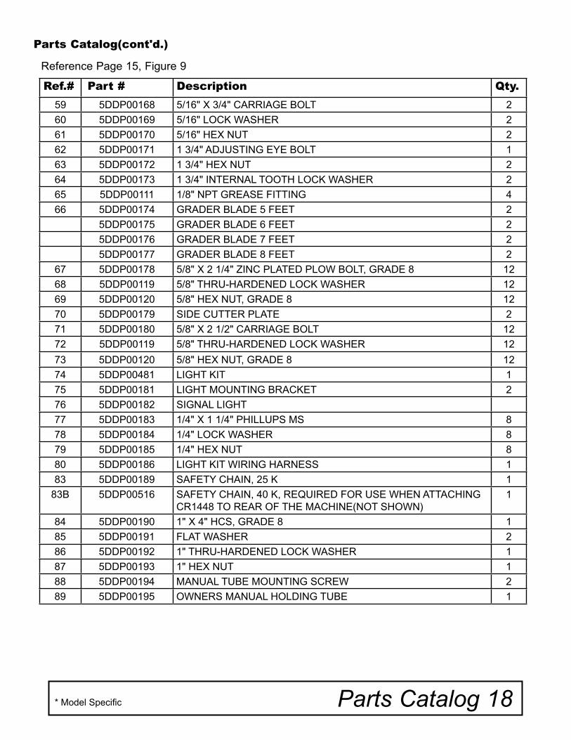
59 5DDP00168 5/16" X 3/4" CARRIAGE BOLT 2
60 5DDP00169 5/16" LOCK WASHER 2
61 5DDP00170 5/16" HEX NUT 2
62 5DDP00171 1 3/4" ADJUSTING EYE BOLT 1
63 5DDP00172 1 3/4" HEX NUT 2
64 5DDP00173 1 3/4" INTERNAL TOOTH LOCK WASHER 2
65 5DDP00111 1/8" NPT GREASE FITTING 4
66 5DDP00174 GRADER BLADE 5 FEET 2
5DDP00175 GRADER BLADE 6 FEET 2
5DDP00176 GRADER BLADE 7 FEET 2
5DDP00177 GRADER BLADE 8 FEET 2
67 5DDP00178 5/8" X 2 1/4" ZINC PLATED PLOW BOLT, GRADE 8 12
68 5DDP00119 5/8" THRU-HARDENED LOCK WASHER 12
69 5DDP00120 5/8" HEX NUT, GRADE 8 12
70 5DDP00179 SIDE CUTTER PLATE 2
71 5DDP00180 5/8" X 2 1/2" CARRIAGE BOLT 12
72 5DDP00119 5/8" THRU-HARDENED LOCK WASHER 12
73 5DDP00120 5/8" HEX NUT, GRADE 8 12
74 5DDP00481 LIGHT KIT 1
75 5DDP00181 LIGHT MOUNTING BRACKET 2
76 5DDP00182 SIGNAL LIGHT
77 5DDP00183 1/4" X 1 1/4" PHILLUPS MS 8
78 5DDP00184 1/4" LOCK WASHER 8
79 5DDP00185 1/4" HEX NUT 8
80 5DDP00186 LIGHT KIT WIRING HARNESS 1
83 5DDP00189 SAFETY CHAIN, 25 K 1
83B 5DDP00516 SAFETY CHAIN, 40 K, REQUIRED FOR USE WHEN ATTACHING CR1448 TO REAR OF THE MACHINE(NOT SHOWN)
1
84 5DDP00190 1" X 4" HCS, GRADE 8 1
85 5DDP00191 FLAT WASHER 2
86 5DDP00192 1" THRU-HARDENED LOCK WASHER 1
87 5DDP00193 1" HEX NUT 1
88 5DDP00194 MANUAL TUBE MOUNTING SCREW 2
89 5DDP00195 OWNERS MANUAL HOLDING TUBE 1
* Model Specific
Reference Page 15, Figure 9
19 Parts Catalog
Parts Catalog(cont'd.)
Ref.# Part # Description Qty.
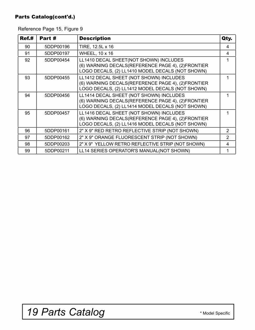
90 5DDP00196 TIRE, 12.5L x 16 4
91 5DDP00197 WHEEL, 10 x 16 4
92 5DDP00454 LL1410 DECAL SHEET(NOT SHOWN) INCLUDES(6) WARNING DECALS(REFERENCE PAGE 4), (2)FRONTIER LOGO DECALS, (2) LL1410 MODEL DECALS (NOT SHOWN)
1
93 5DDP00455 LL1412 DECAL SHEET (NOT SHOWN) INCLUDES(6) WARNING DECALS(REFERENCE PAGE 4), (2)FRONTIER LOGO DECALS, (2) LL1412 MODEL DECALS (NOT SHOWN)
1
94 5DDP00456 LL1414 DECAL SHEET (NOT SHOWN) INCLUDES(6) WARNING DECALS(REFERENCE PAGE 4), (2)FRONTIER LOGO DECALS, (2) LL1414 MODEL DECALS (NOT SHOWN)
1
95 5DDP00457 LL1416 DECAL SHEET (NOT SHOWN) INCLUDES(6) WARNING DECALS(REFERENCE PAGE 4), (2)FRONTIER LOGO DECALS, (2) LL1416 MODEL DECALS (NOT SHOWN)
1
96 5DDP00161 2" X 9" RED RETRO REFLECTIVE STRIP (NOT SHOWN) 2
97 5DDP00162 2" X 9" ORANGE FLUORESCENT STRIP (NOT SHOWN) 2
98 5DDP00203 2" X 9" YELLOW RETRO REFLECTIVE STRIP (NOT SHOWN) 4
99 5DDP00211 LL14 SERIES OPERATOR'S MANUAL(NOT SHOWN) 1
* Model Specific
Reference Page 15, Figure 9
Optional Equipment 20
Optional Equipment
Six different pieces of optional attachments are available for each model of the LL14 Series Land Leveler.
Do not attempt to mount the optional equipment to the drawn box scraper unless you have the proper equipment and experience to perform the job. Failure to do so may cause serious injury.
Follow all safety precautions outlined in the Safety Rules(Pages 5-7) of this manual. To help
If your LL14 Series Land Leveler is equiped with the optional weight rack you can add weight to ensure an aggressive cut in certain conditions.
The weights are added to the frame by lining up the indentions on the weights with the round pegs on the center of the weight frame, and placing the weights equally onto the front and back of each side of the weight frame. The first two weights must be installed as a pair.
To hold six weights or fewer in position, insert retaining bolts through holes and secure with a nut. When eight or more weights are installed,
prevent serious injury to you or others caused by unexpected movement, this procedure should be done on a level surface, preferably concrete. The land leveler should be securely lowered to the floor and blocked to prevent movement and the proper equipment used to safely move the optional equipment in place and bolt to the frame of the land leveler.
After attaching the optional equipment tighten nuts and bolts according to the Bolt and Torque Chart on Page 29.
insert retainers between weights, one with thread-ed hole upward and the other with threaded hole downward. Tighten to specifications according to the Torque and Bolt Chart on Page 29.
A maximum of 32 John Deere 100 lb. suitcase weights can be added to the LL1410 and LL1412.
A maximum of 42 John Deere 100 lb. suitcase weights can be added to the LL1414.
A maximum of 46 John Deere 100 lb. suitcase weights can be added to the LL1416.
WARNING
Hydraulic Scarifier Bar
Hydraulic Smooth Drum Roller
Aggression Bar
Laser Ladder Stand
Hydraulic Hoses
Rear Hitch Assembly
Adding Weight to the OptionalWeight Rack
21 Optional Equipment
Optional Equipment(cont'd.)
Figure 9
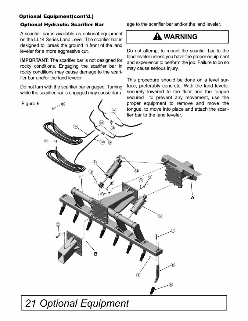
Optional Hydraulic Scarifier Bar
A scarifier bar is available as optional equipment on the LL14 Series Land Level. The scarifier bar is designed to break the ground in front of the land leveler for a more aggressive cut.
IMPORTANT: The scarifier bar is not designed for rocky conditions. Engaging the scarifier bar in rocky conditions may cause damage to the scari-fier bar and/or the land leveler.
Do not turn with the scarifier bar engaged. Turning while the scarifier bar is engaged may cause dam-
age to the scarifier bar and/or the land leveler.
Do not attempt to mount the scarifier bar to the land leveler unless you have the proper equipment and experience to perform the job. Failure to do so may cause serious injury.
This procedure should be done on a level sur-face, preferably concrete. With the land leveler securely lowered to the floor and the tongue secured to prevent any movement, use the proper equipment to remove and move the tongue, to move into place and attach the scari-fier bar to the land leveler.
A
WARNING
B
Optional Equipment 22
Optional Scarifier Bar Parts Catalog, Ref. Figure 9
Ref.# Part # Description Qty.
1 5DDM00503 MAIN FRAME WELDMENT 10 FEET 1
5DDM00578 MAIN FRAME WELDMENT 14 FEET 1
2 5DDP00101 1" X 3 1/2" YELLOW ZINC HCS, GRADE 8 12
3 5DDP00102 1" YELLOW ZINC THRU-HARD LOCKWASHER 12
4 5DDP00103 1" YELLOW ZINC HEX NUT, GRADE 8 12
5 5DDP00104 SCARIFIER SHANK MS
6 5DDP00105 SCARIFIER REPLACEABLE TIP MS
7 5DDM00505 WEDGE PIN MS
8 5DDP00106 1/4" X 1 1/2" SPRING PIN MS
9 5DDP00108 HYDRAULIC CYLINDER 5.0 BORE X 8 STROKE 2
10A 5DDA00030 HYDRAULIC HOSE TOO TEES, 14' AND 10' MODELS, 15' 4" 2
10B 5DDA00031 HYDRAULIC HOSE FROM TEE TO BOTTOM OF CYLINDER, 10' MODEL, 30" 2
5DDA00087 HYDRAULIC HOSE FROM TEE TO BOTTOM OF CYLINDER, 14' MODEL, 6'
10C 5DDA00032 HYDRAULIC HOSE FROM TEE TO TOP OF CYLINDER, 10' MODEL, 2' 2
5DDA00088 HYDRAULIC HOSE FROM TEE TO TOP OF CYLINDER, 14' MODEL, 7'
11 5DDP00109 HYDRAULIC CYLINDER CLEVIS PIN 2
12 5DDP00110 1/8" x 2" COTTER PINS 2
13 5DDP00111 1/8" GREASE FITTING - NPT 1
14 5DDP00112 3000PSI SHUT-OFF BALL VALVE MS
15 5DDP00113 MALE HYDRAULIC TIP 2
15 5DDP00113 MALE HYDRAULIC TIP 2
16 5DDP00220 HYDRAULIC TEE 2
17 5DDP00198 WARNING: DO NOT TURN WITH TOOL ENGAGED DECAL(NOT SHOWN)
2
18 5DDA00085 2 HOSE EXTENSION FOR GRADE KING WITHOUT REAR HY-DRAULICS, 38" (NOT SHOWN)
1
19 5DDA00086 4 HOSE EXTENSION FOR GRADE KING WITH REAR HYDRAU-LICS, 38" (NOT SHOWN)
1
* Model Specific
The scarifier bar attaches to the land leveler at the front hitch plate that the tongue attaches to(Figure 9, Ref. A).
The tongue then reattaches to the front hitch plate of the scarifier bar(Figure 9,Ref. B).
After attaching the scarifier bar tighten nuts and bolts according to the Bolt and Torque Chart on Page 29.
Maintenance
Check scarifier teeth for wear or damage. Replace where necessary.
Lubrication
For maintenance and lubrication locations refer to Page 13, Figure 6.
Hydraulics
For maintenance and correct hydraulic hose con-nections refer to Page 14, Figure 7.
Note: All hydraulic hoses on the LL14 Optional Scarifier Bar are 1/2" diameter. Specific lengths are listed in the parts list.
23 Optional Equipment
Optional Equipment(cont'd.)
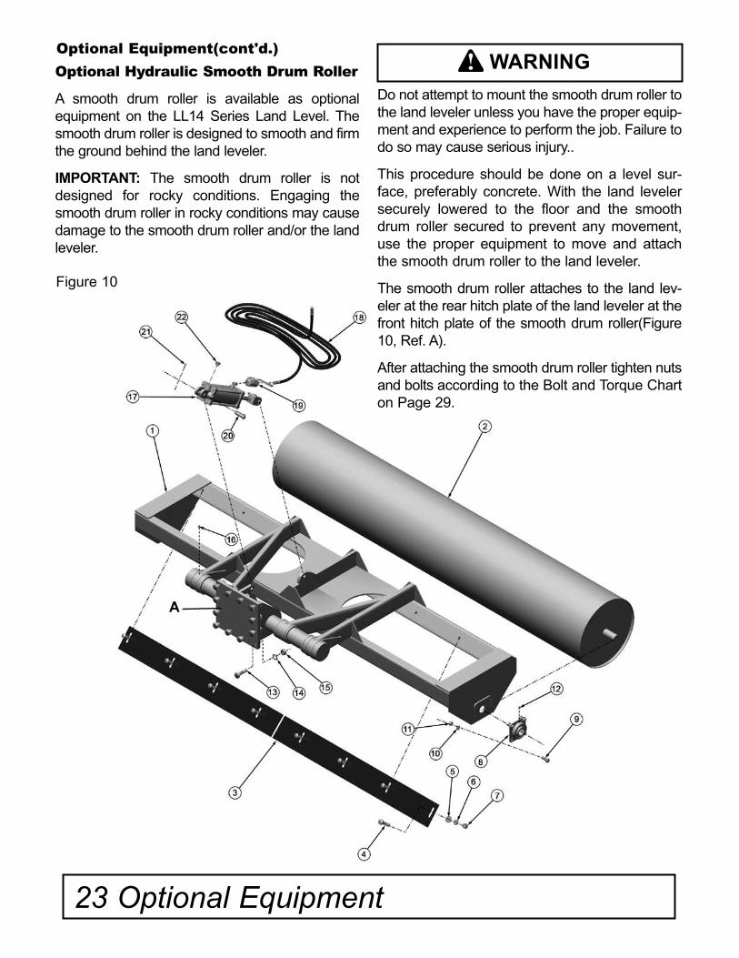
Optional Hydraulic Smooth Drum Roller
A smooth drum roller is available as optional equipment on the LL14 Series Land Level. The smooth drum roller is designed to smooth and firm the ground behind the land leveler.
IMPORTANT: The smooth drum roller is not designed for rocky conditions. Engaging the smooth drum roller in rocky conditions may cause damage to the smooth drum roller and/or the land leveler.
Do not attempt to mount the smooth drum roller to the land leveler unless you have the proper equip-ment and experience to perform the job. Failure to do so may cause serious injury..
This procedure should be done on a level sur-face, preferably concrete. With the land leveler securely lowered to the floor and the smooth drum roller secured to prevent any movement, use the proper equipment to move and attach the smooth drum roller to the land leveler.
The smooth drum roller attaches to the land lev-eler at the rear hitch plate of the land leveler at the front hitch plate of the smooth drum roller(Figure 10, Ref. A).
After attaching the smooth drum roller tighten nuts and bolts according to the Bolt and Torque Chart on Page 29.
WARNING
Figure 10
A
Optional Equipment 24
Optional Hydraulic Smooth Drum Roller Parts Catalog, Ref. Figure 10
Ref.# Part # Description Qty.
1 5DDM00504 MAIN FRAME WELDMENT 10 FEET 1
5DDM00505 MAIN FRAME WELDMENT 12 FEET 1
5DDM00506 MAIN FRAME WELDMENT 14 FEET 1
2 5DDM00507 24" SMOOTH ROLLER 10 FEET 1
5DDM00508 24" SMOOTH ROLLER 12 FEET 1
5DDM00509 24" SMOOTH ROLLER 14 FEET 1
3 5DDM00510 SCRAPER BLADE 5 FEET 2
5DDM00511 SCRAPER BLADE 6 FEET 2
5DDM00512 SCRAPER BLADE 7 FEET 2
4 5DDP00113 5/8"-11" X 3 1/2" HCS, GRADE 8 *MS
5 5DDP00114 5/8" USS THRU-HARDENED FLAT WASHER *MS
6 5DDP00115 5/8" THRU-HARDENED LOCK WASHER *MS
7 5DDP00116 5/8"-11 HEX NUT, GRADE 8 *MS
8 5DDP00117 FOUR BOLT FLANGE BEARING 2
9 5DDP00118 5/8"-11" X 2 1/2" HCS, GRADE 8 8
10 5DDP00119 5/8" THRU-HARDENED LOCK WASHER 8
11 5DDP00120 5/8" HEX NUT, GRADE 8 8
12 5DDP00121 G-1/8" GREASE FITTING 1
13 5DDP00101 1" X 3 1/2" HCS, GRADE 8 12
14 5DDP00102 1" THRU-HARDENED LOCK WASHER 12
15 5DDP00103 1" HEX NUT, GRADE 8 12
16 5DDP00111 1/8" NPT GREASE FITTING 4
17 5DDP00122 HYDRAULIC CYLINDER 5 BORE 8 STROKE 1
18 5DDA00032 HYDRAULIC HOSE ASSEMBLY, 2' 1
19 5DDP00480 3000 PSI SHUT OFF VALVE 1
20 5DDP00109 HYDRAULIC CYLINDER CLEVIS PIN 1
21 5DDP00110 1/8" X 2" COTTER PIN 1
22 5DDP00411 CYLINDER BREATHER 1
23 5DDP00161 2" X 9" RED RETRO REFLECTIVE STRIP (NOT SHOWN) 2
24 5DDP00162 2" X 9" ORANGE FLUORESCENT STRIP (NOT SHOWN) 2
25 5DDP00163 2" X 9" YELLOW REFLECTIVE STRIP (NOT SHOWN) 2
* Model Specific
Maintenance
Check roller for damage or leaks. Replace where necessary.
Lubrication
For maintenance and lubrication locations refer to Page 13, Figure 6.
Hydraulics
For maintenance and correct hydraulic hose con-nections refer to Page 14, Figure 7.
Note: All hydraulic hoses on the LL14 Optional Smooth Drum Roller are 1/2" diameter. Specific lengths are listed in the parts list.
25 Optional Equipment
Optional Equipment(cont'd.)
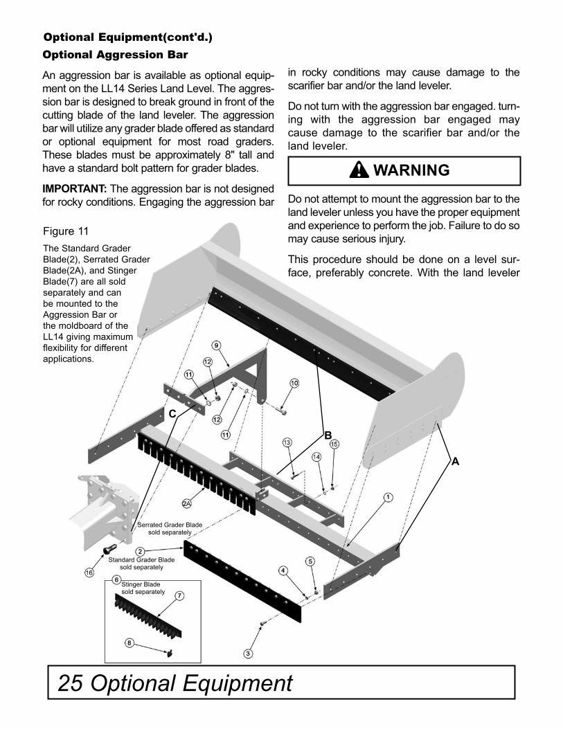
Optional Aggression Bar
An aggression bar is available as optional equip-ment on the LL14 Series Land Level. The aggres-sion bar is designed to break ground in front of the cutting blade of the land leveler. The aggression bar will utilize any grader blade offered as standard or optional equipment for most road graders. These blades must be approximately 8" tall and have a standard bolt pattern for grader blades.
IMPORTANT: The aggression bar is not designed for rocky conditions. Engaging the aggression bar
in rocky conditions may cause damage to the scarifier bar and/or the land leveler.
Do not turn with the aggression bar engaged. turn-ing with the aggression bar engaged may cause damage to the scarifier bar and/or the land leveler.
Do not attempt to mount the aggression bar to the land leveler unless you have the proper equipment and experience to perform the job. Failure to do so may cause serious injury.
This procedure should be done on a level sur-face, preferably concrete. With the land leveler
WARNING
Figure 11
The Standard Grader Blade(2), Serrated Grader Blade(2A), and Stinger Blade(7) are all soldseparately and canbe mounted to theAggression Bar orthe moldboard of theLL14 giving maximumflexibility for differentapplications.
B
A
C
Serrated Grader Blade sold separately
Standard Grader Blade sold separately
Stinger Bladesold separately
Optional Equipment 26
OptionalAggression Bar Parts Catalog, Ref. Figure 11
Ref.# Part # Description Qty.
1 5DDM00522 MAIN FRAME WELDMENT 10 FEET 1
5DDM00523 MAIN FRAME WELDMENT 12 FEET 1
5DDM00524 MAIN FRAME WELDMENT 14 FEET 1
5DDM00525 MAIN FRAME WELDMENT 16 FEET 1
2 5DDP00174 STANDARD GRADER BLADES 5 FEET *MS
5DDP00175 STANDARD GRADER BLADES 6 FEET *MS
5DDP00176 STANDARD GRADER BLADES 7 FEET *MS
5DDP00177 STANDARD GRADER BLADES 8 FEET *MS
2A 5DDP00212 SERRATED GRADER BLADES 3 FEET *MS
5DDP00213 SERRATED GRADER BLADES 4 FEET *MS
3 5DDP00214 5/8" X DOME HEADED PLOW BOLT *MS
4 5DDP00136 5/8" THRU-HARDENED LOCKWASHER *MS
5 5DDP00137 5/8" NUT, GRADE 8 *MS
OPTIONAL STINGER BAR COMPLETE ASSEMBLY
6 PBS36625HD STINGER BAR 3 FEET *MS PBS48625HD STINGER BAR 4 FEET *MS
7 AT164846 REPLACMENT STINGERS *MS
8 5DDM00583 MOUNTING BRACKET 1
9 5DDP00190 1" X 4" ZINC HCS, GRADE 8 1
10 5DDP00102 1" THRU-HARDENED LOCK WASHER 5
11 5DDP00103 1" HEX NUT, GRADE 8 5
12 5DDP00418 5/8" x 3 1/2" HCS, GRADE 8 *MS
13 5DDP00119 5/8" THRU-HARDENED LOCK WASHER *MS
14 5DDP00120 5/8" HEX NUT, GRADE 8 *MS
15 5DDP00471 1" X 4 1/2" ZINC HCS, GRADE 8 4
* Model Specific
securely lowered to the floor use the proper equipment to move and attach the aggression bar to the land leveler.
The aggression bar attaches to the land leveler at each endplate with the same bolts that attach the side cutting plates(Figure 11, Ref. A). It secures to the moldboard with the same bolts that attach the cutting blade to the moldboard (Figure 11, Ref. B) and the center beam with the same bolts used to attach the tongue or scarifier (Figure 11, Ref. C).
After attaching the aggression bar tighten nuts and bolts according to the Bolt and Torque Chart on Page 29.
Maintenance
Check cutting edges and stinger points regularly for wear and damage. Replace where necessary.
27 Optional Equipment
Optional Equipment(cont'd.)
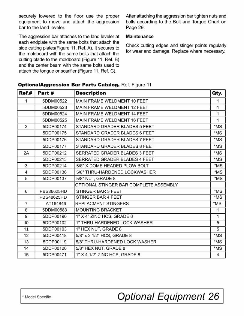
Optional Laser Ladder Stand
A laser ladder is available as optional equipment on the LL14 Series Land Level. The laser ladder GPS and/or laser can be mounted for high speed, precision finish work.
Do not attempt to mount the laser ladder to the land leveler unless you have the proper equipment and experience to perform the job. Failure to do so may cause serious injury.
This procedure should be done on a level sur-face, preferably concrete. The laser ladder mounts onto the land leveler in the same bracket that holds the hydraulic hose coupler bracket(Figure 12, Ref. A). Tighten nuts and bolts according to the Bolt and Torque Chart on Page 29.
WARNING
Figure 12
A
Optional Rear Hydraulic Hoses
An extra set of hydraulic hoses are available as an option on the LL14 Series Land Level.
It is important to keep hydraulics well maintained to prevent strain on the leveler or the tractor.
Check fluids regularly and keep reservoirs filled to proper capacity.
Escaping fluid under pressure can penetrate the skin causing serious injury. Avoid the hazard by relieving pressure before disconnecting hydraulic or other lines. Tighten all connections before applying pressure.
Hydraulic hoses can fail due to physical damage, kinks, age, and exposure. Check hoses regularly, replace damaged hoses.
WARNING
Figure 13
Ref.# Part # Description Qty.
1 5DDM00526 LADDER WELDMENT 1
Ref.# Part # Description Qty.
1 5DDA00004 REAR HITCH ASSEMBLY 1
Optional Equipment 28
Optional Laser Ladder Parts Catalog, Ref. Figure 12
Optional Rear Hitch Assemblies Parts Catalog, Ref. Figure 14
Optional Rear Hydraulic Hoses Parts Catalog, Ref. Figure 13
Ref.# Part # Description Qty.
1 5DDA00036 HYDRAULIC HOSE ASSEMBLY REAR, 7' 2
2 5DDA00037 HYDRAULIC HOSE ASSEMBLY TONGUE, 12' 6" 2
3 5DDP00164 HYDRAULIC COUPLING 2
4 5DDP00219 HYDRAULIC COUPLER MOUNTING BRACKET 1
5 5DDP00165 BULK HEAD UNION 2
6 5DDP00113 MALE HYDRAULIC TIP 2
Figure 14Optional Equipment(cont'd.)
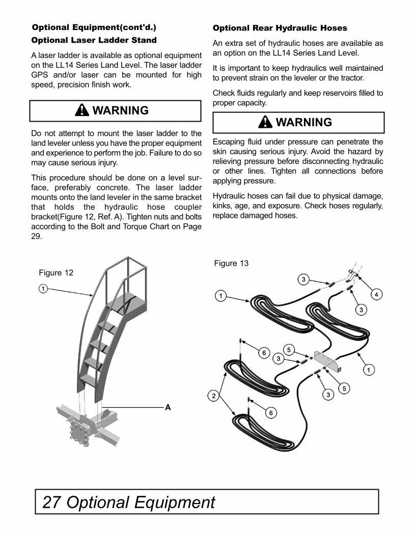
Optional Rear Hitch Assembly
An optional rear hitch receiver is available to allow attachmnets to be pulled behind the LL14 Series Land Leveler. The optional hitch receiver bolts to the rear end plate of the land leveler.
Note: All hydraulic hoses on the LL14 Optional Hydraulic Hoses are 1/2" diameter. Specific lengths are listed in the parts list.
29 Bolt and Torque Chart

Notes
Notes 30

© 2008 DoubleD Manufacturing . All Rights Reserved
PART NO.5DDP00211


![GMK5150B NA Brochure[1] - LEC Construction · 220 0 10 20 30 40 50 60 70 80 90 100 110 120 130 140 150 160 170 180 190 200 210 230 240 250 260 270 feet 200 210 feet 190 180 170 160](https://static.fdocuments.net/doc/165x107/5f526af093815119cd1d5781/gmk5150b-na-brochure1-lec-220-0-10-20-30-40-50-60-70-80-90-100-110-120-130-140.jpg)