Operator’s Manual Contains: Safety Summary Lift … · Lift Terminology Decals Locations...
30
Operator’s Manual Contains: Safety Summary Lift Terminology Decals Locations Operating Instructions M-00-37 REV. B JUNE 2003
-
Upload
duongthuan -
Category
Documents
-
view
219 -
download
0
Transcript of Operator’s Manual Contains: Safety Summary Lift … · Lift Terminology Decals Locations...

Operator’s Manual Contains: Safety Summary
Lift TerminologyDecals Locations
Operating Instructions
M-00-37REV. B
JUNE 2003


TABLE OF CONTENTS
INTRODUCTION ....................................................................... 4
SAFETY SUMMARY ......................................................................... 4
DAILY OPERATION CHECKLIST .................................................... 7
LIFT TERMINOLOGY ................................................................ 8
DECALS AND DECAL PLACEMENT ............................................. 10
OPERATING INSTRUCTIONS ...................................................... 14
PRESSURIZE LIFT ................................................................. 15
ENTER VEHICLE ................................................................... 16
EXIT VEHICLE ....................................................................... 19
STOW LIFT FROM VEHICLE FLOOR..................................... 21
STOW LIFT FROM GROUND LEVEL ..................................... 21
MANUAL PUMP OPERATION ....................................................... 23
UNLOADING OCCUPANT ...................................................... 23
LOADING OCCUPANT ........................................................... 27

4
11921 Slauson Ave. Santa Fe Springs, CA
. 90670 (800) 227-4116 FAX
(888) 771-7713
1. This Wheelchair Lift is intended for Commercial Useand to be operated by an Attendant. Do Not attempt toride Lift without the assistance of an Attendant.
2. Incorrect operation of this Lift can result in seriouspersonal injury. Comply with the WARNINGS andLift operating instructions in this manual. Do not allowuntrained persons to operate the Lift. If you need toreplace an Operator’s Manual, additional copies areavailable from:
MAXON Lift Corp.11921 Slauson Ave
Santa Fe Springs, CA 90670(800) 227-4116
3. Do not exceed rated load capacity of Lift which is800 lbs. (364 kg).
4. Do not allow any part of your body, or the Lift occupant’sbody, to be placed under, within, or around any portionof the moving Lift or its mechanisms, or in a positionthat would trap them between the platform and theground (or vehicle) when Lift is operated.
5. Consider the safety and location of bystanders andlocation of nearby objects when operating the Lift. Standto one side of platform while operating the Lift. Be certainthat the area the Lift will move through during operationis clear of all obstacles.
INTRODUCTION
This manual contains safety information and operating instructions for theMaxon Wheelchair and Standing Occupant Lift. Read and understand theWARNINGS, SAFETY CONSIDERATIONS, and operating instructions inthis manual, before operating the Lift.
SAFETY SUMMARY

5
1192
1 Sl
auso
n Av
e.
Sant
a Fe
Spr
ings
, CA
. 90
670
(80
0) 2
27-4
116
FA
X (
888)
771
-771
3
6. Fasten Occupant Restraint Belt Before Operating Lift,but never tighten the belt. Leave a minimum of 3”-4”slack in the belt. Lift will not operate correctly and maybecome a hazard if belt is tight.
7. If Lift is not operated for several days or more it mayneed to be repressurized. Use manual pump topressurize the system before operating the Lift again.Low hydraulic pressure may cause Lift to operateincorrectly and become a hazard.
8. Always operate the Lift with the vehicle emergency brakeset and vehicle parked on Level ground. Operating Liftwithout emergency brake set or parked on an inclinemay create a hazard for occupant and attendant.
9. Comply with all attached instruction decals and warningdecals.
10. Above all, USE GOOD COMMON SENSE whenoperating this Lift.
11. Do not move vehicle when door is open.
ADDITIONAL SAFETY CONSIDERATIONS
1. When using the Lift, wheelchair may face outboard orinboard. If possible, position the wheelchair withoccupant facing outboard.
2. Standing occupant may face outboard or inboard. Ifpossible, position standing occupant on the Lift, facingthe direction of travel (face vehicle when entering orface away when exiting).

6
11921 Slauson Ave. Santa Fe Springs, CA
. 90670 (800) 227-4116 FAX
(888) 771-7713
THIS PAGE INTENTIONALLY LEFT BALNK

7
1192
1 Sl
auso
n Av
e.
Sant
a Fe
Spr
ings
, CA
. 90
670
(80
0) 2
27-4
116
FA
X (
888)
771
-771
3DAILY OPERATION CHECKLIST
NOTE: Operation checks should be performed by the Lift Operator.
1. Before operating the Wheelchair Lift:
Park vehicle on level ground, shift vehicle transmission toPARK, and set vehicle emergency brake.
From inside of vehicle, visually inspect Lift for bent or broken parts orhydraulic fluid around the base.
Observe if any Lift components appear bent or broken.
Check the indicator light on the Lift pump cover. If indicator isilluminated, vehicle power is available to operate the Lift.
NOTE: If any of the before operating checks have incorrect indica-tions, do not operate the Lift until repairs are performed by a quali-fied technician.
2. Operate the Lift through one cycle.
Use Lift operating instructions in this manual to UNFOLD,LOWER, RAISE, and FOLD platform.
Make sure the Lift responds properly to hand controlswitches.
Listen for unusual noises while the Lift operates.
Watch for uneven movement of the Lift arms, platform, andinboard and outboard rollstops.
NOTE: If any of the Lift operating checks have incorrect indications,discontinue operating Lift until repairs are performed by a qualifiedtechnician.

8
11921 Slauson Ave. Santa Fe Springs, CA
. 90670 (800) 227-4116 FAX
(888) 771-7713
LIFT TERMINOLOGY
Lift references used throughout this manual are defined belowand illustrated on opposite page.
METI EMAN NOITPIRCSED
1 .YSSAMRAGNILEVARTskniLrewoLdnareppU)thgiR/tfeL(
nomrAlacitreVhcaegnitcennoc.ylbmessAesaBotylbmessAmroftalP
2 TNIARTSERTNAPUCCO
stcatahttlebasitniartseRtnapuccOriahcleehWehtpeekotreirrabasatsumtleB.mroftalPehtffognillormorf
.noitarepotratsotdegagneeb
3 .YSSAPOTSLLORDRAOBTUOmorfriahcleehWehttneverpotreirraB
oslA.mroftalPehtfoffognillor.mroftalprofpmartixe/yrtnesedivorp
4 YLBMESSAMROFTALPtnapuccOdnariahcleehWehtsdloH
.noitarepo"NWOD/PU"gnirud.dnuorgehtdnaroolfelcihevneewteb
5 )HR/HL(LIARDNAH tfiLehtrofdlohdnahasedivorP.tnapucco
6 .YSSAPOTSLLORDRAOBNI
morfriahcleehWehttneverpotreirraB.mroftalpfoedisdraobniffognillortfiLneewtebegdirbsedivorp,oslA
.dlohserhTrooDelciheVdnamroftalP
7 YLBMESSAELKCUNK ehtsdlofhcihwegakniL)thgiR/tfeL(.mroftalP
8 REDNILYCCILUARDYHtahtebuTleetSgnipocseleT)thgiR/tfeL(
sevomdna,tfilehtsdlofnudnasdlof.nwoddnaputfileht
9 TINUREWOPCILUARDYHsenildiulf,pmupciluardyhsniatnoCciluardyhehtetarepootslortnocdna
.srednilyc
01 YLBMESSAESAB ehtnotfiLstnuomtahtylbmessA.roolfelcihev

9
1192
1 Sl
auso
n Av
e.
Sant
a Fe
Spr
ings
, CA
. 90
670
(80
0) 2
27-4
116
FA
X (
888)
771
-771
3LIFT TERMINOLOGY
INBOARD
LEFT
RIGHT
OUTBOARD
2
8
9
8
16
1
10
7
4
3
5
5

10
11921 Slauson Ave. Santa Fe Springs, CA
. 90670 (800) 227-4116 FAX
(888) 771-7713
The Maxon Wheelchair Lift must have all warning and cautiondecals attached in readable condition. If decals are defaced or missing,replace them. Free replacements are available from Maxon. Contact:
Maxon Lift Corp., Parts Department11921 Slauson Ave., Santa Fe Springs, Ca.90670
Phone: (800) 227-4116FAX: (888) 771-7713
DECALS AND DECAL PLACEMENT
DECAL “N”
DECAL “A”
DECAL “D”
DECAL “K”
DECAL “E”
DECAL “C”
DECAL “B”
DECAL“L”
DECAL“O”
DECAL“J”
DECAL “M”
DECAL“G”
DECAL “H”DECAL “I”
DECAL “F”
DECAL“O”

11
1192
1 Sl
auso
n Av
e.
Sant
a Fe
Spr
ings
, CA
. 90
670
(80
0) 2
27-4
116
FA
X (
888)
771
-771
3
DECAL “E” P/N 266313-01
DECAL “C” P/N 266313-01
DECAL “D” P/N 266313-01
DECAL “A” P/N 266313-01 DECAL “B” P/N 266313-01

12
11921 Slauson Ave. Santa Fe Springs, CA
. 90670 (800) 227-4116 FAX
(888) 771-7713
DECALS AND DECAL PLACEMENT - Continued
DECAL “F” P/N 261389 DECAL “G” P/N 265352
DECAL “H” P/N 905272 DECAL “I” P/N 265112

13
1192
1 Sl
auso
n Av
e.
Sant
a Fe
Spr
ings
, CA
. 90
670
(80
0) 2
27-4
116
FA
X (
888)
771
-771
3
DECAL “K” P/N 265325
DECAL “J” P/N 265110
DECAL “L” P/N 261444
DECAL “N” P/N 261357 DECAL “O” P/N 261367
DECAL “M” P/N 261353

14
11921 Slauson Ave. Santa Fe Springs, CA
. 90670 (800) 227-4116 FAX
(888) 771-7713
OPERATING INSTRUCTIONS

15
1192
1 Sl
auso
n Av
e.
Sant
a Fe
Spr
ings
, CA
. 90
670
(80
0) 2
27-4
116
FA
X (
888)
771
-771
3
If Lift is not operated for several days or more it may need tobe repressurized. Use manual pump to pressurize the systembefore operating the Lift or opening lift access door on vehicleagain. Low hydraulic pressure may cause Lift to operateincorrectly and become a hazard.
PRESSURIZE LIFT
1/2
TU R N
1. Make sure pressure release valve is closed as follows. Close pressurerelease valve on pump by using MANUAL BACKUP HANDLE to turn valvefitting 1/2 turn clockwise (FIG. 1). Insert MANUAL BACKUP HANDLE inmanual pump actuator. Pump the handle up and down (FIG. 2) until youfeel resistance.
FIG. 1 CLOSING PRESSURERELEASE VALVE
FIG. 2 PUMPING MANUAL BACKUP HANDLE
2. Store MANUAL BACKUP HANDLE on outside of pump cover byfastening handle in the clips provided.

16
11921 Slauson Ave. Santa Fe Springs, CA
. 90670 (800) 227-4116 FAX
(888) 771-7713
ENTER VEHICLE
FIG.3 UNFOLD PLATFORM
FIG.4 WHEELCHAIR LIFT HAND CONTROL
DOWN
UNFOLD UP
FOLD
1. Fully open and secure Wheelchair Lift access door(s) on the vehicle.
2. Activate UNFOLD switch on Lift HAND CONTROL (FIG.4) to openPLATFORM to horizontal position (FIG.3).

17
1192
1 Sl
auso
n Av
e.
Sant
a Fe
Spr
ings
, CA
. 90
670
(80
0) 2
27-4
116
FA
X (
888)
771
-771
3
3. Activate DOWN switch on Lift HAND CONTROL (FIG. 4) to lowerPLATFORM to ground level (FIG. 5).
4. Unfasten OCCUPANT RESTRAINT BELT (FIG. 6), and place on hookprovided.
5. Position Wheelchair centrally on Lift PLATFORM (FIG. 7) and LOCK WHEELCHAIR BRAKES.
6. Fasten OCCUPANT RESTRAINT BELT allowing 3” - 4” of slack (FIG. 8).
FIG. 5 LOWER PLATFORMTO GROUND
FIG. 7 TYPICAL ATTENDANT POSITIONINGOCCUPANT ON PLATFORM
FIG. 8 FASTEN OCCUPANT RESTRAINT BELT
FIG. 6 UNFASTEN OCCUPANT RESTRAINT BELT

18
11921 Slauson Ave. Santa Fe Springs, CA
. 90670 (800) 227-4116 FAX
(888) 771-7713
DOWN
UNFOLD UP
FOLD
7. Activate UP switch on Lift HAND CONTROL (FIG. 9) to raise PLAT-FORM to vehicle floor level (FIG. 10).
FIG. 9 WHEELCHAIR LIFT HAND CONTROL
FIG. 10 RAISING LIFT UP TO VEHICLE FLOOR LEVEL
8. RELEASE WHEELCHAIR BRAKES and enter vehicle.
ENTER VEHICLE - Continued

19
1192
1 Sl
auso
n Av
e.
Sant
a Fe
Spr
ings
, CA
. 90
670
(80
0) 2
27-4
116
FA
X (
888)
771
-771
3
1. Fully open and secure Wheelchair Lift access door(s) on the vehicle.
2. Activate UNFOLD switch on Lift HAND CONTROL (FIG. 9) to openPLATFORM to horizontal position (FIG. 11).
3. Make sure OCCUPANT RESTRAINT BELT is fastened (FIG. 12) with3” - 4” of slack in belt.
4. Position wheelchair centrally on PLATFORM (FIG. 13) and LOCKWHEELCHAIR BRAKES.
FIG. 13 TYPICAL ATTENDANT POSITIONINGOCCUPANT ON PLATFORM
EXIT VEHICLE
FIG.11 UNFOLD PLATFORM
FIG. 12 FASTEN OCCUPANT RESTRAINT BELT

20
11921 Slauson Ave. Santa Fe Springs, CA
. 90670 (800) 227-4116 FAX
(888) 771-7713
5. Activate DOWN switch on Lift HAND CONTROL (FIG. 15) to lowerPLATFORM to ground level (FIG. 14).
FIG. 14 LOWER PLATFORM TO GROUND
6. Unfasten OCCUPANT RESTRAINT BELT (FIG. 16) and place on hookprovided.
7. RELEASE WHEELCHAIR BRAKES and exit platform.
DOWN
UNFOLD UP
FOLD
FIG. 15 WHEELCHAIR LIFT HAND CONTROL
FIG. 16 UNFASTEN OCCUPANTRESTRAINT BELT
EXIT VEHICLE - Continued

21
1192
1 Sl
auso
n Av
e.
Sant
a Fe
Spr
ings
, CA
. 90
670
(80
0) 2
27-4
116
FA
X (
888)
771
-771
3
2. Activate UP switch on Lift HAND CONTROL (FIG.20) to raise PLAT-FORM to vehicle floor level (FIG. 19).
STOW LIFT FROM GROUND LEVEL
1. Activate FOLD switch on Lift HAND CONTROL (FIG.19) to closePLATFORM (FIG. 17). Fold operation will stop automatically whencompleted.
STOW LIFT FROM VEHICLE FLOOR
FIG. 17 FOLDING PLATFORM UP INTO VEHICLE
FIG. 19 RAISING LIFT UP TO VEHICLE FLOOR LEVEL
FIG. 18 FASTEN OCCUPANT RESTRAINT BELT
1. Fasten OCCUPANT RESTRAINT BELT (FIG. 18) leaving 3” - 4” of slackin belt.

22
11921 Slauson Ave. Santa Fe Springs, CA
. 90670 (800) 227-4116 FAX
(888) 771-7713
3. Activate FOLD switch on Lift HAND CONTROL (FIG. 20) to closePLATFORM (FIG. 21). Fold operation will stop automatically whencompleted.
DOWN
UNFOLD UP
FOLD
FIG.20 WHEELCHAIR LIFT HAND CONTROL
FIG. 21 FOLDING PLATFORMUP INTO VEHICLE
STOW LIFT FROM GROUND LEVEL - Continued

23
1192
1 Sl
auso
n Av
e.
Sant
a Fe
Spr
ings
, CA
. 90
670
(80
0) 2
27-4
116
FA
X (
888)
771
-771
3
1. Remove MANUAL BACKUP HANDLE from clips on the pump cover.
NOTE: Manual pump operating instructions for the Lift are also locatedon pump cover. See DECALS AND DECAL PLACEMENT in thismanual.
2. Unfold Lift PLATFORM as follows. Open pressure release valve onpump by using MANUAL BACKUP HANDLE to turn valve fitting 1/2turn counter-clockwise (FIG. 22).
3. Observe PLATFORM unfolding to horizontal position at vehicle floorlevel (FIG. 23).
MANUAL PUMP OPERATION
FIG. 23 UNFOLD PLATFORM
UNLOADING OCCUPANT
FIG. 22 OPEN PRESSURERELEASE VALVE
1/2
T U RN

24
11921 Slauson Ave. Santa Fe Springs, CA
. 90670 (800) 227-4116 FAX
(888) 771-7713
MANUAL PUMP OPERATION - Continued
4. When PLATFORM reaches floor level, close pressure release valve onpump by using MANUAL BACKUP HANDLE to turn valve fitting 1/2 turnclockwise (FIG. 24).
5. Ensure OUTBOARD ROLLSTOP is locked in the up position (FIG. 25).
6. Ensure OCCUPANT RESTRAINT BELT (FIG. 26) is fastened. Allow3” - 4” of slack in belt.
FIG. 25 OUTBOARD ROLLSTOPIN UP POSITION
1/2
TU R N
FIG. 24 CLOSE PRESSURERELEASE VALVE
FIG. 26 FASTEN OCCUPANT RESTRAINT BELT
OUTBOARDROLLSTOP
UNLOADING OCCUPANT

25
1192
1 Sl
auso
n Av
e.
Sant
a Fe
Spr
ings
, CA
. 90
670
(80
0) 2
27-4
116
FA
X (
888)
771
-771
3
7. Unpin ACTUATOR BRACKET (FIG. 27) from ACTUATOR. ManuallyLOWER the INBOARD ROLLSTOP to BASE PLATE (FIG. 28).
FIG. 27 FIG. 28
8. Roll wheelchair (or guide standing occupant) out to middle ofPLATFORM (FIG. 29). LOCK WHEELCHAIR BRAKES.
FIG. 29 TYPICAL ATTENDANT POSITIONINGOCCUPANT ON PLATFORM
INBOARDROLLSTOP
BASE PLATE
ACTUATORBRACKET
9. Manually RAISE the INBOARD ROLLSTOP (FIG. 30). Pin ACTUA-TOR BRACKET to ACTUATOR (FIG. 30).
FIG. 30
INBOARDROLLSTOP
PIN
ACTUATOR
ACTUATORBRACKET
ACTUATOR
PIN

26
11921 Slauson Ave. Santa Fe Springs, CA
. 90670 (800) 227-4116 FAX
(888) 771-7713
MANUAL PUMP OPERATION - Continued
12. Unfasten OCCUPANT RESTRAINT BELT (FIG. 33). Store on hanger provided.
13. Roll wheelchair (or guide standing occupant) off the PLATFORM andinto the unloading area.
FIG. 33 UNFASTEN OCCUPANTRESTRAINT BELT
11. Watch PLATFORM (FIG. 32) as it lowers occupant to the ground.
10. Lower Lift PLATFORM as follows. Re-enter the vehicle to accessmanual pump. Open pressure release valve on pump by usingMANUAL BACKUP HANDLE to turn valve fitting 1/2 turn counter-clockwise (FIG. 31).
1/2T U R
N
FIG. 31 OPEN PRESSURE RELEASE VALVE
FIG. 32 LOWER PLATFORM TO GROUND
UNLOADING OCCUPANT
27
1192
1 Sl
auso
n Av
e.
Sant
a Fe
Spr
ings
, CA
. 90
670
(80
0) 2
27-4
116
FA
X (
888)
771
-771
3
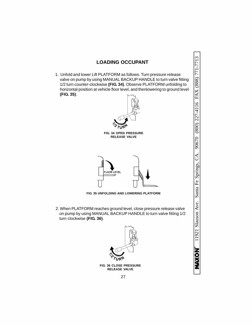
1. Unfold and lower Lift PLATFORM as follows. Turn pressure releasevalve on pump by using MANUAL BACKUP HANDLE to turn valve fitting1/2 turn counter-clockwise (FIG. 34). Observe PLATFORM unfolding tohorizontal position at vehicle floor level, and thenlowering to ground level(FIG. 35).
2. When PLATFORM reaches ground level, close pressure release valveon pump by using MANUAL BACKUP HANDLE to turn valve fitting 1/2turn clockwise (FIG. 36).
LOADING OCCUPANT
1/2
TU R N
FIG. 36 CLOSE PRESSURERELEASE VALVE
FIG. 35 UNFOLDING AND LOWERING PLATFORM
1/2
T U RN
FIG. 34 OPEN PRESSURERELEASE VALVE

28
11921 Slauson Ave. Santa Fe Springs, CA
. 90670 (800) 227-4116 FAX
(888) 771-7713
MANUAL PUMP OPERATION - Continued
3. Ensure OUTBOARD ROLLSTOP on Lift PLATFORM is opened to thehorizontal position (FIG. 37).
5. Roll wheelchair (or guide standing occupant) to the middle of PLAT-FORM (FIG.39).
4. Unfasten OCCUPANT RESTRAINT BELT (FIG. 38). Store on hangerprovided.
6. Fasten OCCUPANT RESTRAINT BELT (FIG. 40). Allow 3” - 4” of slackin belt.
FIG. 37 OUTBOARD ROLLSTOP IN HORIZONTAL POSITION
OUTBOARDROLLSTOP
FIG. 38 UNFASTEN OCCUPANTRESTRAINT BELT
FIG. 39 TYPICAL OCCUPANT POSITIONEDON PLATFORM
FIG. 40 FASTEN OCCUPANTRESTRAINT BELT
LOADING OCCUPANT

29
1192
1 Sl
auso
n Av
e.
Sant
a Fe
Spr
ings
, CA
. 90
670
(80
0) 2
27-4
116
FA
X (
888)
771
-771
3
7. Raise Lift PLATFORM as follows. Insert MANUAL BACKUP HANDLEin manual pump actuator. Pump the handle up and down (FIG. 41) untilPLATFORM is raised up even with the vehicle floor level (FIG. 42).
FIG. 41 PUMPING MANUAL BACKUP HANDLE
FIG. 42 RAISING LIFT UP TO VEHICLE FLOOR LEVEL
8. Unpin ACTUATOR BRACKET (FIG. 43) from ACTUATOR. ManuallyLOWER the INBOARD ROLLSTOP to BASE PLATE (FIG. 44).
FIG. 43 FIG. 44
INBOARDROLLSTOP
BASE PLATE
ACTUATORBRACKET
ACTUATOR
PIN

30
11921 Slauson Ave. Santa Fe Springs, CA
. 90670 (800) 227-4116 FAX
(888) 771-771311. Fold PLATFORM (FIG. 48) up into vehicle by pumping MANUAL
BACKUP HANDLE up and down (FIG. 47) until PLATFORM iscompletely folded.
12. Store MANUAL BACKUP HANDLE on outside of pump cover byfastening handle in the clips provided.
MANUAL PUMP OPERATION - Continued
9. Roll wheelchair (or guide standing occupant) into vehicle (FIG.45). Secure occupant in vehicle with correct restraint belts.
FIG. 45 TYPICAL ATTENDANT WITHOCCUPANT ON PLATFORM
10. Manually RAISE the INBOARD ROLLSTOP (FIG. 46). Pin ACTUATORBRACKET to ACTUATOR (FIG. 46).
FIG. 46
INBOARDROLLSTOP
PIN
ACTUATOR
ACTUATORBRACKET
FIG. 47 PUMPING MANUAL BACKUP HANDLE
FIG. 48 FOLDING PLATFORM UP INTO VEHICLE
LOADING OCCUPANT