Operators Manual - cdn.webfactore.co.ukcdn.webfactore.co.uk/4908_pme200+operators+manual.pdf ·...
71
562200-000, Issue1.1, April 2013 PME 200 Rated Capacity Indicator, Machine Envelope Indicator Rated Capacity Controller, Machine Envelope Controller Operators Manual
Transcript of Operators Manual - cdn.webfactore.co.ukcdn.webfactore.co.uk/4908_pme200+operators+manual.pdf ·...
562200-000, Issue1.1, April 2013
PME 200 Rated Capacity Indicator, Machine Envelope Indicator
Rated Capacity Controller, Machine Envelope Controller
Operators Manual

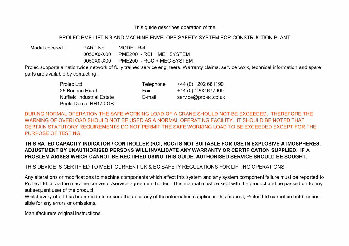
This guide describes operation of the
PROLEC PME LIFTING AND MACHINE ENVELOPE SAFETY SYSTEM FOR CONSTRUCTION PLANT
Model covered : PART No. MODEL Ref
0050X0-X00 PME200 - RCI + MEI SYSTEM
0050X0-X00 PME200 - RCC + MEC SYSTEM
Prolec supports a nationwide network of fully trained service engineers. Warranty claims, service work, technical information and spare
parts are available by contacting :
Prolec Ltd Telephone +44 (0) 1202 681190
25 Benson Road Fax +44 (0) 1202 677909
Nuffield Industrial Estate E-mail [email protected]
Poole Dorset BH17 0GB
DURING NORMAL OPERATION THE SAFE WORKING LOAD OF A CRANE SHOULD NOT BE EXCEEDED. THEREFORE THE
WARNING OF OVERLOAD SHOULD NOT BE USED AS A NORMAL OPERATING FACILITY. IT SHOULD BE NOTED THAT
CERTAIN STATUTORY REQUIREMENTS DO NOT PERMIT THE SAFE WORKING LOAD TO BE EXCEEDED EXCEPT FOR THE
PURPOSE OF TESTING.
THIS RATED CAPACITY INDICATOR / CONTROLLER (RCI, RCC) IS NOT SUITABLE FOR USE IN EXPLOSIVE ATMOSPHERES.
ADJUSTMENT BY UNAUTHORISED PERSONS WILL INVALIDATE ANY WARRANTY OR CERTIFICATION SUPPLIED. IF A
PROBLEM ARISES WHICH CANNOT BE RECTIFIED USING THIS GUIDE, AUTHORISED SERVICE SHOULD BE SOUGHT.
THIS DEVICE IS CERTIFIED TO MEET CURRENT UK & EC SAFETY REGULATIONS FOR LIFTING OPERATIONS.
Any alterations or modifications to machine components which affect this system and any system component failure must be reported to
Prolec Ltd or via the machine convertor/service agreement holder. This manual must be kept with the product and be passed on to any
subsequent user of the product.
Whilst every effort has been made to ensure the accuracy of the information supplied in this manual, Prolec Ltd cannot be held respon-
sible for any errors or omissions.
Manufacturers original instructions.
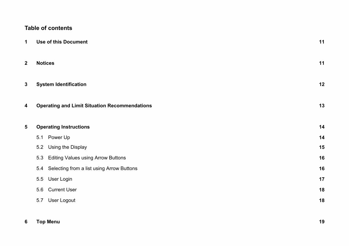
Table of contents
1 Use of this Document 11
2 Notices 11
3 System Identification 12
4 Operating and Limit Situation Recommendations 13
5 Operating Instructions 14
5.1 Power Up 14
5.2 Using the Display 15
5.3 Editing Values using Arrow Buttons 16
5.4 Selecting from a list using Arrow Buttons 16
5.5 User Login 17
5.6 Current User 18
5.7 User Logout 18
6 Top Menu 19
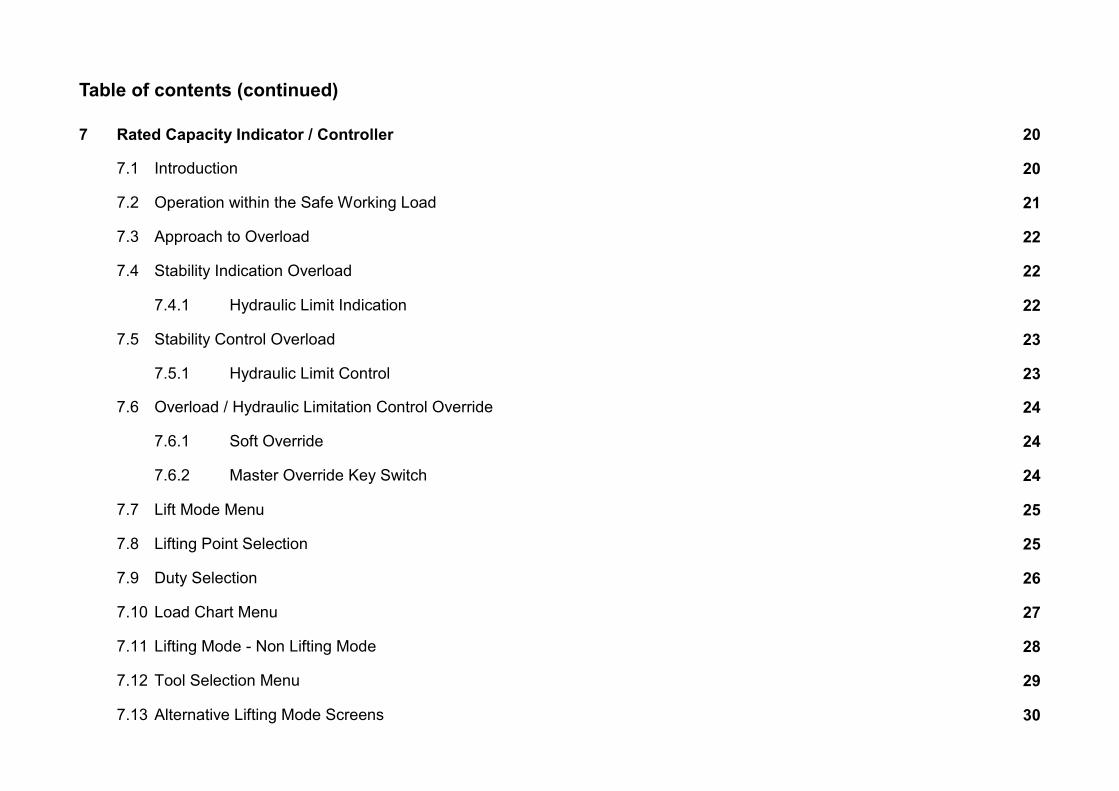
Table of contents (continued)
7 Rated Capacity Indicator / Controller 20
7.1 Introduction 20
7.2 Operation within the Safe Working Load 21
7.3 Approach to Overload 22
7.4 Stability Indication Overload 22
7.4.1 Hydraulic Limit Indication 22
7.5 Stability Control Overload 23
7.5.1 Hydraulic Limit Control 23
7.6 Overload / Hydraulic Limitation Control Override 24
7.6.1 Soft Override 24
7.6.2 Master Override Key Switch 24
7.7 Lift Mode Menu 25
7.8 Lifting Point Selection 25
7.9 Duty Selection 26
7.10 Load Chart Menu 27
7.11 Lifting Mode - Non Lifting Mode 28
7.12 Tool Selection Menu 29
7.13 Alternative Lifting Mode Screens 30
Table of contents (continued)
8 Envelope Monitoring 31
8.1 Height Limit 32
8.1.1 Height Limit Menu 32
8.1.2 Height Limit Setting - Known Height 33
8.1.3 Height Limit Setting - Using Current Highest Point 34
8.1.4 Machine Envelope Indicator (MEI) - Height 35
8.1.5 Machine Envelope Controller (MEC) - Height 36
8.2 Max Radius Limit 37
8.2.1 Max Radius Limit Menu 37
8.2.2 Max Radius Limit Setting - Known Radius 38
8.2.3 Max Radius Limit Setting - Using Current Max Radius 39
8.2.4 Machine Envelope Indicator (MEI) - Max Radius 40
8.2.5 Machine Envelope Controller (MEC) - Max Radius 41
Continued
Table of contents (continued)
8.3 Min Radius Limit 42
8.3.1 Min Radius Limit Menu 42
8.3.2 Min Radius Limit Setting - Known Min Radius 43
8.3.3 Min Radius Limit Setting - Using Current Min Radius 44
8.3.4 Machine Envelope Indicator (MEI) - Min Radius 45
8.3.5 Machine Envelope Controller (MEC) - Min Radius 46
8.4 Low Limit 47
8.4.1 Low Limit Menu 47
8.4.2 Low Limit Setting - Known Radius 48
8.4.3 Low Limit Setting - Using Current Lowest Point 49
8.4.4 Machine Envelope Indicator (MEI) - Low 50
8.4.5 Machine Envelope Controller (MEC) - Low 51
Continued
Table of contents (continued)
9 Warning Messages
9.1 On Screen Messages 52
9.2 LED and Internal Alarm Warnings 53
10 Daily checks 53
11 Test / Diagnostics 54
11.1 Relay Function Test 55
11.2 Beacon, LED Alarm Function Test 55
12 Display Settings 56
12.1 Day / Night Mode 56
12.2 Select Display Machine 57
12.3 Select Language 57
13 System Information 58
Table of contents - continued
14 Taking Product out of Operation 58
15 Service and Repair 59
15.1 Maintenance Review 59
15.2 Time / Date 60
15.2.1 Time / Date Adjustment 60
15.3 Radius / Height 62
15.4 Pressure Transducers 62
15.5 Safe Working Load 63
16 User Login 63
16.1 User Login Setup 63
16.2 Add New User 64
16.3 Edit User Details 65
16.4 Select User to Delete 66
16.5 Edit User Access Code 66
16.6 Enable / Disable Users 67

Table of contents - continued
17 Repair 67
18 Definitions / Glossary 68
562200-000, Issue1.1, April 2013
11 of 71
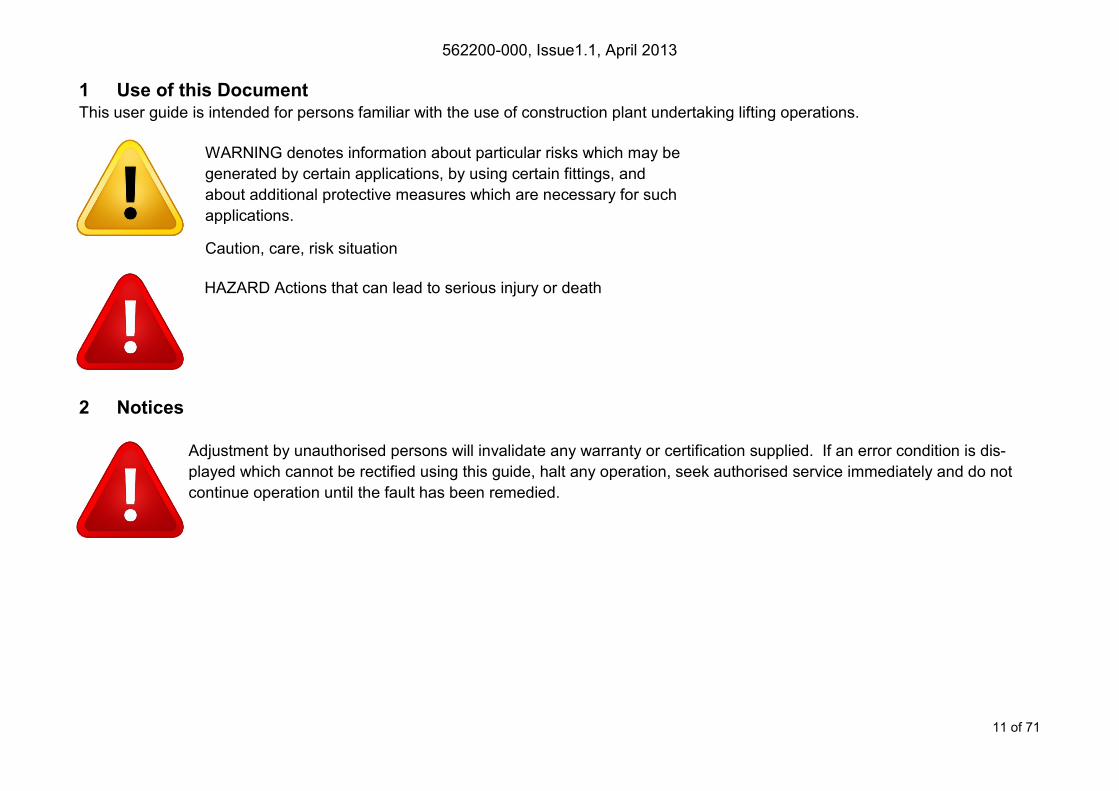
1 Use of this Document This user guide is intended for persons familiar with the use of construction plant undertaking lifting operations.
2 Notices
Adjustment by unauthorised persons will invalidate any warranty or certification supplied. If an error condition is dis-
played which cannot be rectified using this guide, halt any operation, seek authorised service immediately and do not
continue operation until the fault has been remedied.
WARNING denotes information about particular risks which may be
generated by certain applications, by using certain fittings, and
about additional protective measures which are necessary for such
applications.
Caution, care, risk situation
HAZARD Actions that can lead to serious injury or death

562200-000, Issue1.1, April 2013
12 of 71
3 System Identification
The PME system provides two primary safety functions
1. Lifting Stability
2. Machine Envelope Monitoring
Both safety functions are achieved through real time monitoring some or all of the machine’s moving parts ( booms,
other articulations, turret etc ) and its environment ( ground pitch and inclination, load etc) and actively determining the
safety of the current operation where appropriate limits have been set.
The Lifting Stability function falls into two sub classes
Rated capacity indictors (RCI) warn of potential instability when the machine is involved in lifting operations. Any
motion which reduces the safe working load will not be inhibited at any time.
Rated capacity controllers (RCC) prevent instability when the machine is involved in lifting operations. This is
achieved by hydraulically stopping unsafe movements of the machine which could cause the machine to tip.
The Machine Envelope Monitoring function also is divided into two sub classes
Machine envelope indictors (MEI) warn of movements that would bring parts of the machine into hazardous ar-
eas, most notably height restrictions when working under overhead wires. Any motion which exceeds the set limit
will not be inhibited at any time.
Machine envelope controllers (MEC) prevent movements that would bring parts of the machine into hazardous
areas, most notably height restrictions when working under overhead wires.
During operation the indicators on the left are displayed on the screen to clearly identify the function supported by your
PME 200. Functions may not be available i.e. when in non-lifting mode or when envelope monitoring is switched off, if
this is the case a cross will be painted over the relevant function icon.
Combinations of these functions may be present, it is essential that the functions of the system installed are identified
and understood.
562200-000, Issue1.1, April 2013
13 of 71
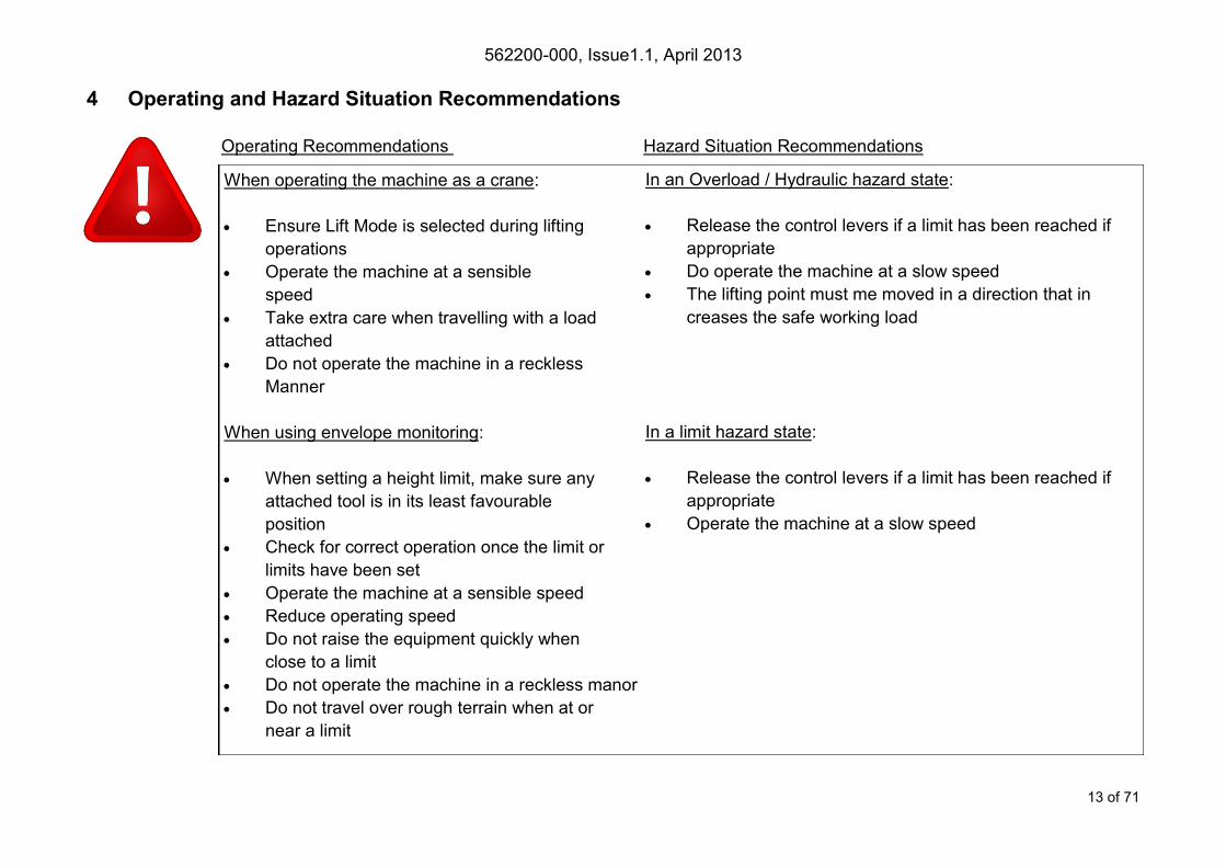
4 Operating and Hazard Situation Recommendations
Operating Recommendations Hazard Situation Recommendations
When operating the machine as a crane:
Ensure Lift Mode is selected during lifting
operations
Operate the machine at a sensible
speed
Take extra care when travelling with a load
attached
Do not operate the machine in a reckless
Manner
When using envelope monitoring:
When setting a height limit, make sure any
attached tool is in its least favourable
position
Check for correct operation once the limit or
limits have been set
Operate the machine at a sensible speed
Reduce operating speed
Do not raise the equipment quickly when
close to a limit
Do not operate the machine in a reckless manor
Do not travel over rough terrain when at or
near a limit
In an Overload / Hydraulic hazard state:
Release the control levers if a limit has been reached if
appropriate
Do operate the machine at a slow speed
The lifting point must me moved in a direction that in
creases the safe working load
In a limit hazard state:
Release the control levers if a limit has been reached if
appropriate
Operate the machine at a slow speed

562200-000, Issue1.1, April 2013
14 of 71
5 Operating Instructions
5.1 Power Up The PME system automatically powers up when the machines ignition is
switched on. The in-cab unit incorporates a 4.3” high resolution LCD display
and is controlled with three buttons at each side. Three status LEDs and an
internal alarm provide further information.
The system will perform a self check at start up:
1. All LEDs will flash, the internal display alarm and the external alarm will
sound.
2. The RED LED will light indicating the system is starting and performing
a self test.
3. Once the self test is complete, the GREEN LED will light and the system will become active. A safety warming message is dis-
played, please read and proceed only if you are fully familiar with your PME system. Lifting Mode is activated by pressing any key
and any previous limits set will be enabled. The system is now ready for use.
4. The system can be configured to require a user login - if this is enabled, see section 5.5.
If the RED LED remains lit, a fault has been detected, halt any operation, seek authorised service immediately and do
not continue operation until the fault has been remedied.
The display is secured to the machine using a flexible ball mounting allowing easy adjustment for personal viewing preference.

562200-000, Issue1.1, April 2013
15 of 71
5.2 Using the Display
The display is operated by using the buttons adjacent to a function icon. The
buttons can open a sub menu, turn a function ON or OFF, set a value, toggle
through multiple screens, no one button has a single function. The button icon
will turn black/purple when the button has been activated. Note that the image
of the machine is fixed and does not follow the movement of the machine.
A secondary symbol can appear in the top left corner of an icon, these mean :
The plus symbol indicates a sub menu will be opened if selected.
The cycle symbol indicates that multiple features are available.
The on / off symbols indicate if a feature is ON or OFF. Red is ON and grey is OFF.
Help is available for each button. To access the help, push and hold the button for three seconds.
The help message can be cleared by pressing any of the six buttons. PME is still active when dis-
playing help messages, if the Lifting Mode is active and or a height limit is set, any alarm or warning
condition will be indicated.
Multifunction buttons:
The action of the button is
indicated by the adjacent
icon.
562200-000, Issue1.1, April 2013
16 of 71
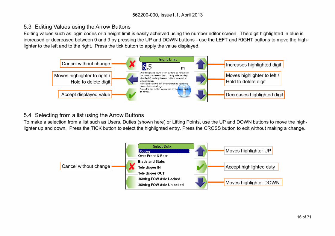
5.3 Editing Values using the Arrow Buttons Editing values such as login codes or a height limit is easily achieved using the number editor screen. The digit highlighted in blue is
increased or decreased between 0 and 9 by pressing the UP and DOWN buttons - use the LEFT and RIGHT buttons to move the high-
lighter to the left and to the right. Press the tick button to apply the value displayed.
5.4 Selecting from a list using the Arrow Buttons To make a selection from a list such as Users, Duties (shown here) or Lifting Points, use the UP and DOWN buttons to move the high-
lighter up and down. Press the TICK button to select the highlighted entry. Press the CROSS button to exit without making a change.
Increases highlighted digit
Decreases highlighted digit
Moves highlighter to left /
Hold to delete digit
Moves highlighter to right /
Hold to delete digit
Accept displayed value
Cancel without change
Moves highlighter UP
Moves highlighter DOWN
Accept highlighted duty Cancel without change

562200-000, Issue1.1, April 2013
17 of 71
5.5 User Login If PME has been configured to work with the built-in user list, the system will prompt for a user login pass code. Select the user name
required and the login code screen will appear.
Using the arrow buttons to enter a valid pass code. The previous number will be replaced with a star as the code is entered. Press the
TICK button to confirm the login pass code. If a valid pass code is entered the system will commence normal operation.
If an incorrect login code is entered, a failure screen will be displayed. Press the TICK button to return to the Select User screen.
Increases highlighted digit
Accept displayed value Decreases highlighted digit
Moves highlighter UP
Exit to enter
calibration area
Moves highlighter DOWN
Select highlighted name, opens
Enter Login Code screen below
Cancel without change
Moves highlighter to left /
Hold to delete number
Moves highlighter to right /
Hold to delete digit
562200-000, Issue1.1, April 2013
18 of 71
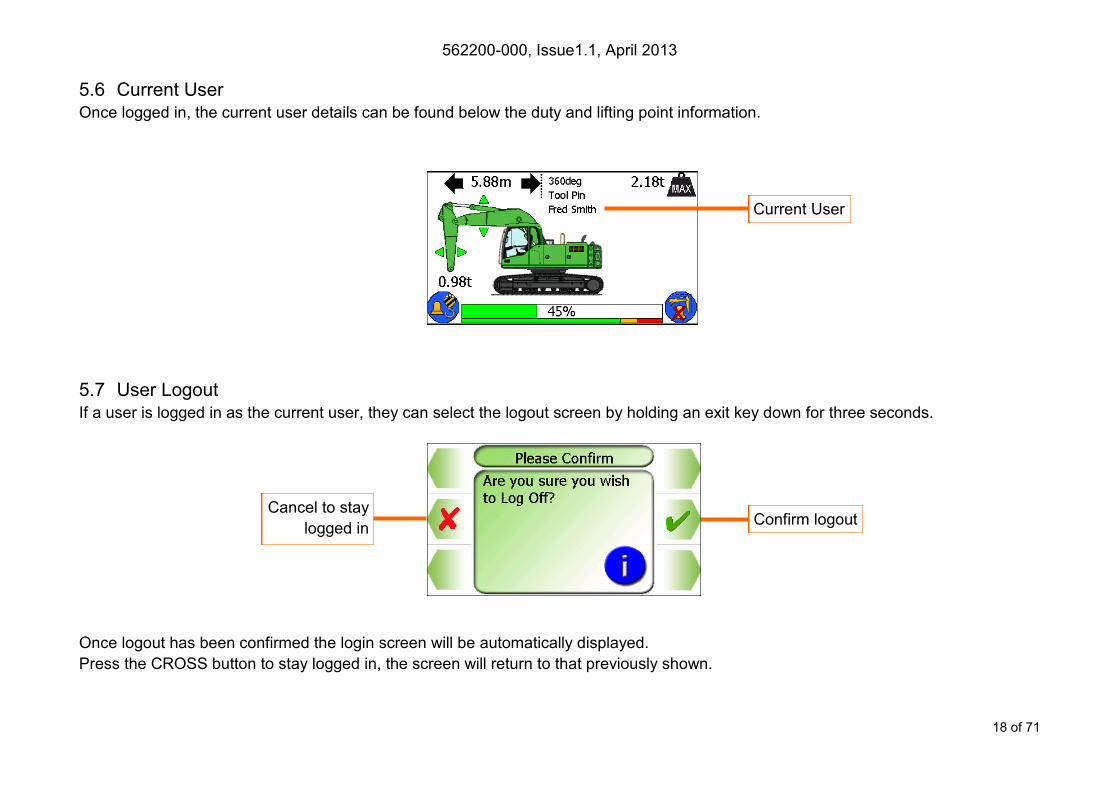
5.6 Current User Once logged in, the current user details can be found below the duty and lifting point information.
5.7 User Logout If a user is logged in as the current user, they can select the logout screen by holding an exit key down for three seconds.
Once logout has been confirmed the login screen will be automatically displayed.
Press the CROSS button to stay logged in, the screen will return to that previously shown.
Cancel to stay
logged in Confirm logout
Current User
562200-000, Issue1.1, April 2013
19 of 71
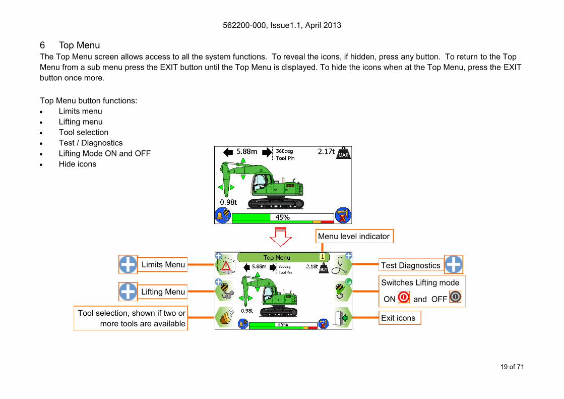
6 Top Menu The Top Menu screen allows access to all the system functions. To reveal the icons, if hidden, press any button. To return to the Top
Menu from a sub menu press the EXIT button until the Top Menu is displayed. To hide the icons when at the Top Menu, press the EXIT
button once more.
Top Menu button functions:
Limits menu
Lifting menu
Tool selection
Test / Diagnostics
Lifting Mode ON and OFF
Hide icons
Limits Menu Test Diagnostics
Exit icons
Lifting Menu
Menu level indicator
Switches Lifting mode
ON and OFF
Tool selection, shown if two or
more tools are available
562200-000, Issue1.1, April 2013
20 of 71
7 Rated Capacity Indicator / Controller
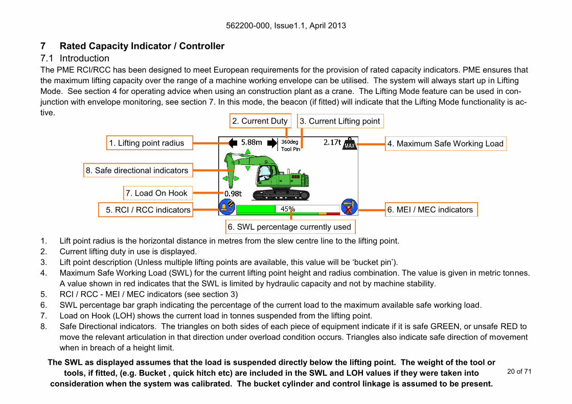
7.1 Introduction The PME RCI/RCC has been designed to meet European requirements for the provision of rated capacity indicators. PME ensures that
the maximum lifting capacity over the range of a machine working envelope can be utilised. The system will always start up in Lifting
Mode. See section 4 for operating advice when using an construction plant as a crane. The Lifting Mode feature can be used in con-
junction with envelope monitoring, see section 7. In this mode, the beacon (if fitted) will indicate that the Lifting Mode functionality is ac-
tive.
1. Lift point radius is the horizontal distance in metres from the slew centre line to the lifting point.
2. Current lifting duty in use is displayed.
3. Lift point description (Unless multiple lifting points are available, this value will be ‘bucket pin’).
4. Maximum Safe Working Load (SWL) for the current lifting point height and radius combination. The value is given in metric tonnes.
A value shown in red indicates that the SWL is limited by hydraulic capacity and not by machine stability.
5. RCI / RCC - MEI / MEC indicators (see section 3)
6. SWL percentage bar graph indicating the percentage of the current load to the maximum available safe working load.
7. Load on Hook (LOH) shows the current load in tonnes suspended from the lifting point.
8. Safe Directional indicators. The triangles on both sides of each piece of equipment indicate if it is safe GREEN, or unsafe RED to
move the relevant articulation in that direction under overload condition occurs. Triangles also indicate safe direction of movement
when in breach of a height limit.
The SWL as displayed assumes that the load is suspended directly below the lifting point. The weight of the tool or
tools, if fitted, (e.g. Bucket , quick hitch etc) are included in the SWL and LOH values if they were taken into
consideration when the system was calibrated. The bucket cylinder and control linkage is assumed to be present.
2. Current Duty 3. Current Lifting point
1. Lifting point radius
8. Safe directional indicators
7. Load On Hook
4. Maximum Safe Working Load
6. MEI / MEC indicators
6. SWL percentage currently used
5. RCI / RCC indicators
562200-000, Issue1.1, April 2013
21 of 71
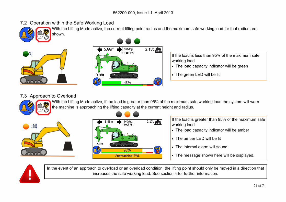
7.2 Operation within the Safe Working Load With the Lifting Mode active, the current lifting point radius and the maximum safe working load for that radius are
shown.
7.3 Approach to Overload With the Lifting Mode active, if the load is greater than 95% of the maximum safe working load the system will warn
the machine is approaching the lifting capacity at the current height and radius.
In the event of an approach to overload or an overload condition, the lifting point should only be moved in a direction that
increases the safe working load. See section 4 for further information.
If the load is greater than 95% of the maximum safe
working load.
The load capacity indicator will be amber
The amber LED will be lit
The internal alarm will sound
The message shown here will be displayed.
If the load is less than 95% of the maximum safe
working load
The load capacity indicator will be green
The green LED will be lit

562200-000, Issue1.1, April 2013
22 of 71
7.4 Stability Indication Overload The system indicates an overload condition via internal and external alarms only - no motion is cut.
7.4.1 Hydraulic Limit Indication If a particular lift is limited by hydraulic capacity rather than stability, the maximum safe working
load will be shown in RED. Hydraulic limitation is more likely to occur at short radii.
If the load is greater than 105% of the maximum
safe working load
The load capacity indicator will be red
The red LED will flash
The internal and external alarm will sound
The message shown here will be displayed
Unsafe motion is indicated by RED arrows, safe
motion is indicated by GREEN arrows
In the event of an approach to overload or an overload condition, the lifting point should only be moved in a direction that
increases the safe working load. See section 4 for further information.
562200-000, Issue1.1, April 2013
23 of 71
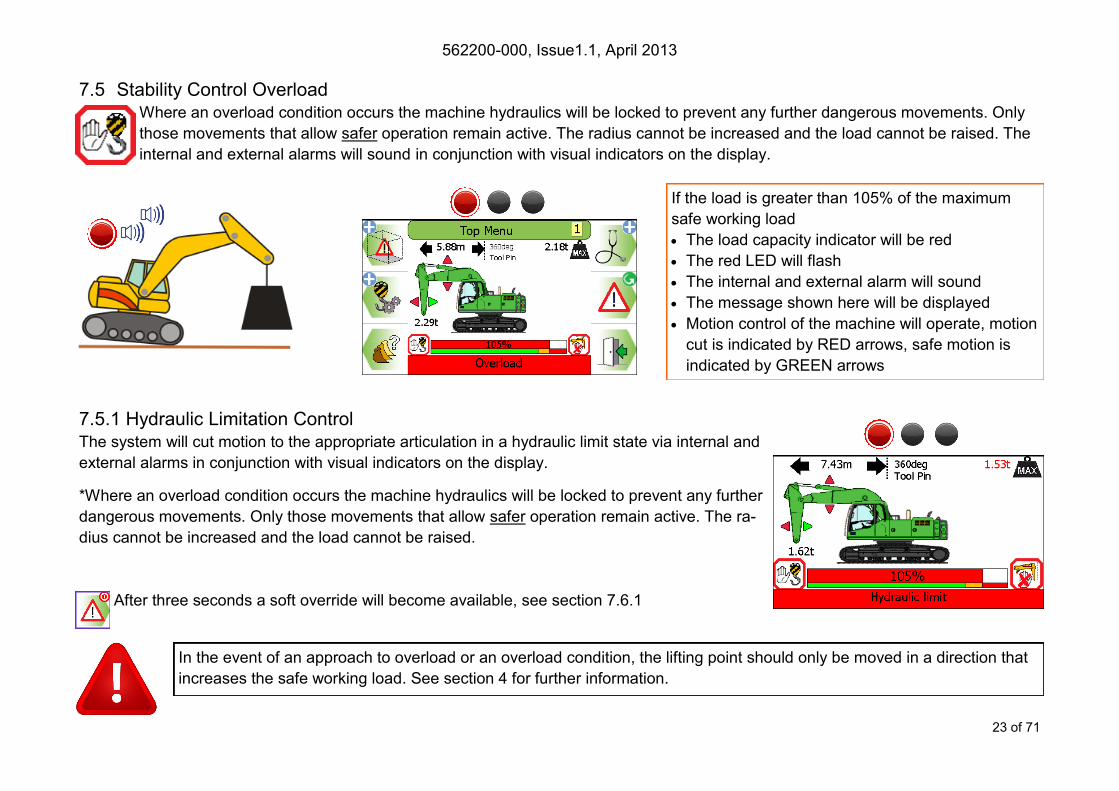
7.5 Stability Control Overload Where an overload condition occurs the machine hydraulics will be locked to prevent any further dangerous movements. Only
those movements that allow safer operation remain active. The radius cannot be increased and the load cannot be raised. The
internal and external alarms will sound in conjunction with visual indicators on the display.
7.5.1 Hydraulic Limitation Control The system will cut motion to the appropriate articulation in a hydraulic limit state via internal and
external alarms in conjunction with visual indicators on the display.
*Where an overload condition occurs the machine hydraulics will be locked to prevent any further
dangerous movements. Only those movements that allow safer operation remain active. The ra-
dius cannot be increased and the load cannot be raised.
After three seconds a soft override will become available, see section 7.6.1
If the load is greater than 105% of the maximum
safe working load
The load capacity indicator will be red
The red LED will flash
The internal and external alarm will sound
The message shown here will be displayed
Motion control of the machine will operate, motion
cut is indicated by RED arrows, safe motion is
indicated by GREEN arrows
In the event of an approach to overload or an overload condition, the lifting point should only be moved in a direction that
increases the safe working load. See section 4 for further information.

562200-000, Issue1.1, April 2013
24 of 71
7.6 Overload / Hydraulic Limitation Control Override
7.6.1 Soft Override After three seconds a soft override button will replace the Lifting Mode button. If soft override is utilised, the machine hydrau-
lics will be re-enabled. However, the external alarm will stay active, the red LED will flash, and the beacon (if fitted) will
switch off. Once the alarm condition has been corrected the RCC will automatically clear the override request and revert to
normal operation.
7.6.2 Master Override key Switch The system can optionally be fitted with a key operated Master override switch. Turning the switch to the override posi-
tion will allow normal operation of any of the hydraulic services regardless of safety status. When the unit is in override
the external alarms will stay active, and the beacon (if fitted) will indicate that the machine is overridden, the red LED
will flash and an In Override message will appear on the display. See section 4.1 for further details.
Soft override
562200-000, Issue1.1, April 2013
25 of 71
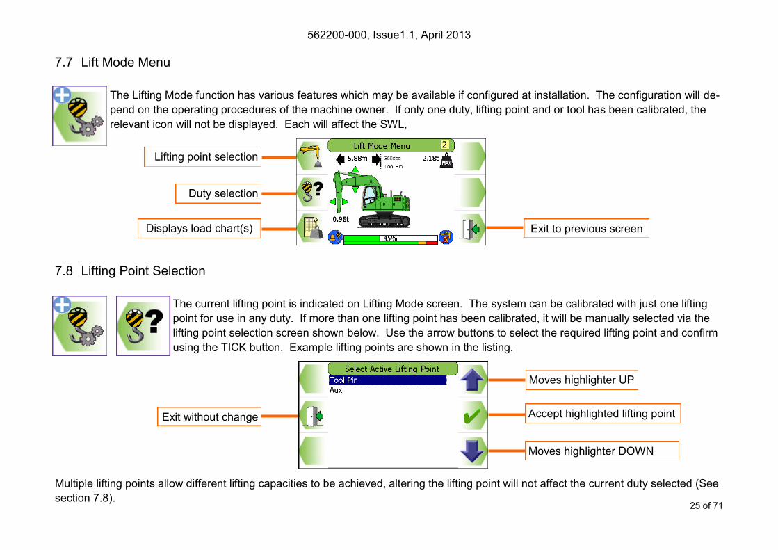
7.7 Lift Mode Menu
The Lifting Mode function has various features which may be available if configured at installation. The configuration will de-
pend on the operating procedures of the machine owner. If only one duty, lifting point and or tool has been calibrated, the
relevant icon will not be displayed. Each will affect the SWL,
7.8 Lifting Point Selection
The current lifting point is indicated on Lifting Mode screen. The system can be calibrated with just one lifting
point for use in any duty. If more than one lifting point has been calibrated, it will be manually selected via the
lifting point selection screen shown below. Use the arrow buttons to select the required lifting point and confirm
using the TICK button. Example lifting points are shown in the listing.
Multiple lifting points allow different lifting capacities to be achieved, altering the lifting point will not affect the current duty selected (See
section 7.8).
Moves highlighter UP
Exit without change
Moves highlighter DOWN
Accept highlighted lifting point
Displays load chart(s) Exit to previous screen
Lifting point selection
Duty selection
562200-000, Issue1.1, April 2013
26 of 71
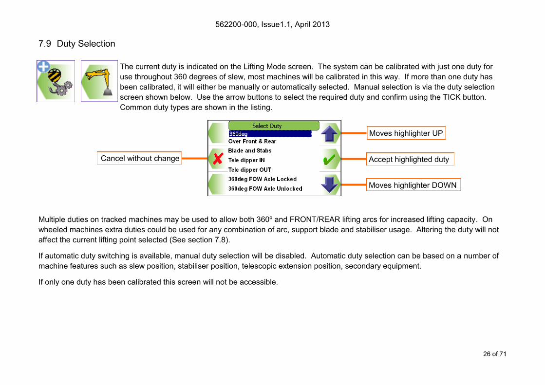
7.9 Duty Selection
The current duty is indicated on the Lifting Mode screen. The system can be calibrated with just one duty for
use throughout 360 degrees of slew, most machines will be calibrated in this way. If more than one duty has
been calibrated, it will either be manually or automatically selected. Manual selection is via the duty selection
screen shown below. Use the arrow buttons to select the required duty and confirm using the TICK button.
Common duty types are shown in the listing.
Multiple duties on tracked machines may be used to allow both 360º and FRONT/REAR lifting arcs for increased lifting capacity. On
wheeled machines extra duties could be used for any combination of arc, support blade and stabiliser usage. Altering the duty will not
affect the current lifting point selected (See section 7.8).
If automatic duty switching is available, manual duty selection will be disabled. Automatic duty selection can be based on a number of
machine features such as slew position, stabiliser position, telescopic extension position, secondary equipment.
If only one duty has been calibrated this screen will not be accessible.
Moves highlighter UP
Cancel without change
Moves highlighter DOWN
Accept highlighted duty
562200-000, Issue1.1, April 2013
27 of 71
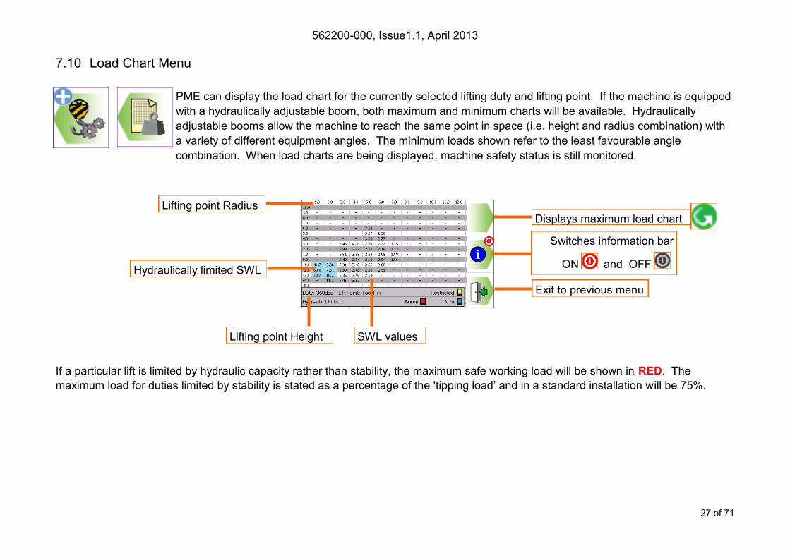
Exit to previous menu
Displays maximum load chart
7.10 Load Chart Menu
PME can display the load chart for the currently selected lifting duty and lifting point. If the machine is equipped
with a hydraulically adjustable boom, both maximum and minimum charts will be available. Hydraulically
adjustable booms allow the machine to reach the same point in space (i.e. height and radius combination) with
a variety of different equipment angles. The minimum loads shown refer to the least favourable angle
combination. When load charts are being displayed, machine safety status is still monitored.
If a particular lift is limited by hydraulic capacity rather than stability, the maximum safe working load will be shown in RED. The
maximum load for duties limited by stability is stated as a percentage of the ‘tipping load’ and in a standard installation will be 75%.
Lifting point Radius
Lifting point Height SWL values
Hydraulically limited SWL
Switches information bar
ON and OFF

562200-000, Issue1.1, April 2013
28 of 71
7.11 Lifting Mode - Non Lifting Mode
When the machine is not being used for lifting operations it can be put into ‘Non Lifting Mode’ from the
Top Menu screen. This option allows the machine to be used for digging etc. When in Non Lifting Mode,
the system still monitors all machine activity and safety status but will NOT warn of overload conditions.
In this mode, the beacon (if fitted) will indicate that the Lifting Mode functionality is NOT active. Lifting mode cannot be acti-
vated if the LOH value exceeds a predefined weight. Envelope Limit monitoring will remain active if any limit has been set.
Lifting Mode ON
Lifting Mode OFF Note Lift Mode button is not accessible
When in Non Lifting Mode, the screen states NON-LIFTING MODE on the hazard warning tape and a red cross appears in
the RCI RCC indicator - lifting operations should not be attempted in this state. The beacon (if fitted) will be off.
562200-000, Issue1.1, April 2013
29 of 71
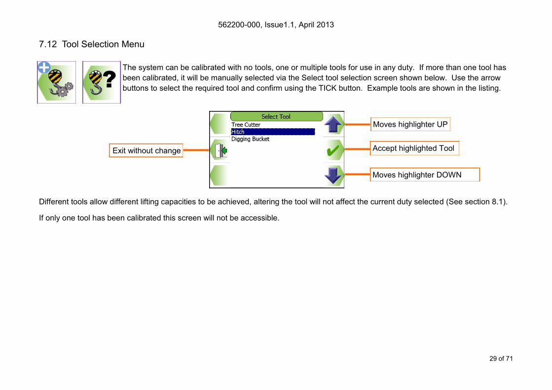
7.12 Tool Selection Menu
The system can be calibrated with no tools, one or multiple tools for use in any duty. If more than one tool has
been calibrated, it will be manually selected via the Select tool selection screen shown below. Use the arrow
buttons to select the required tool and confirm using the TICK button. Example tools are shown in the listing.
Different tools allow different lifting capacities to be achieved, altering the tool will not affect the current duty selected (See section 8.1).
If only one tool has been calibrated this screen will not be accessible.
Moves highlighter UP
Exit without change
Moves highlighter DOWN
Accept highlighted Tool
562200-000, Issue1.1, April 2013
30 of 71
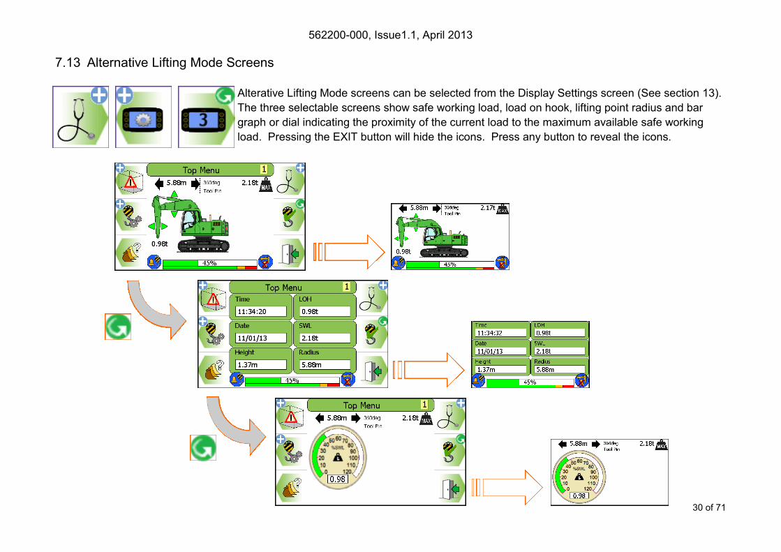
7.13 Alternative Lifting Mode Screens
Alterative Lifting Mode screens can be selected from the Display Settings screen (See section 13).
The three selectable screens show safe working load, load on hook, lifting point radius and bar
graph or dial indicating the proximity of the current load to the maximum available safe working
load. Pressing the EXIT button will hide the icons. Press any button to reveal the icons.
562200-000, Issue1.1, April 2013
31 of 71
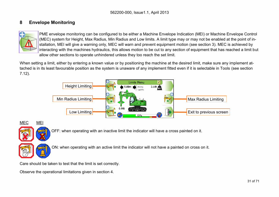
8 Envelope Monitoring
PME envelope monitoring can be configured to be either a Machine Envelope Indication (MEI) or Machine Envelope Control
(MEC) system for Height, Max Radius, Min Radius and Low limits. A limit type may or may not be enabled at the point of in-
stallation, MEI will give a warning only, MEC will warn and prevent equipment motion (see section 3). MEC is achieved by
interacting with the machines hydraulics, this allows motion to be cut to any section of equipment that has reached a limit but
allow other sections to operate unhindered unless they too reach the set limit.
When setting a limit, either by entering a known value or by positioning the machine at the desired limit, make sure any implement at-
tached is in its least favourable position as the system is unaware of any implement fitted even if it is selectable in Tools (see section
7.12).
MEC MEI
OFF: when operating with an inactive limit the indicator will have a cross painted on it.
ON: when operating with an active limit the indicator will not have a painted on cross on it.
Care should be taken to test that the limit is set correctly.
Observe the operational limitations given in section 4.
Exit to previous screen
Height Limiting
Min Radius Limiting
Low Limiting
Max Radius Limiting
562200-000, Issue1.1, April 2013
32 of 71
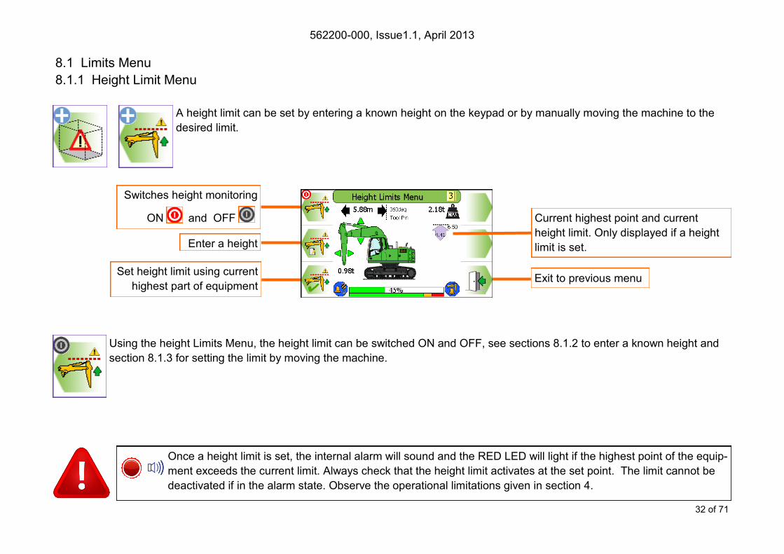
8.1 Limits Menu
8.1.1 Height Limit Menu
A height limit can be set by entering a known height on the keypad or by manually moving the machine to the
desired limit.
Using the height Limits Menu, the height limit can be switched ON and OFF, see sections 8.1.2 to enter a known height and
section 8.1.3 for setting the limit by moving the machine.
Once a height limit is set, the internal alarm will sound and the RED LED will light if the highest point of the equip-
ment exceeds the current limit. Always check that the height limit activates at the set point. The limit cannot be
deactivated if in the alarm state. Observe the operational limitations given in section 4.
Enter a height
Set height limit using current
highest part of equipment Exit to previous menu
Switches height monitoring
ON and OFF Current highest point and current
height limit. Only displayed if a height
limit is set.

562200-000, Issue1.1, April 2013
33 of 71
8.1.2 Height Limit Setting - Known Height
A known limit can be entered into the display:
Press the ’Enter a value’ button
Use the UP and DOWN arrows to increase and decrease the highlighted number. Use the LEFT and RIGHT arrows to move the high-
lighter to the left and to the right.
Increases highlighted digit
Decreases highlighted digit Accept displayed value
Cancel without change
Moves highlighter to left /
Hold to delete digit
Moves highlighter to right /
Hold to delete digit
Enter a value
Exit to previous menu
Once a limit is set, the internal alarm will sound and the RED LED will light if the equipment exceeds the current
limit. Always check that the limit activates at the set point. The limit cannot be deactivated if in the alarm state.
Observe the operational limitations given in section 4.

562200-000, Issue1.1, April 2013
34 of 71
8.1.3 Height Limit Setting - Using Current Highest Point
Move equipment to required
height limit and press this button
To set the height limit using the machine, move the
equipment to the desired maximum height, and press
the ‘current highest point’ button. A confirmation box
will appear reporting the height set. Press the TICK
button to continue.

562200-000, Issue1.1, April 2013
35 of 71
8.1.4 Machine Envelope Indicator (MEI) - Height If any of the equipment enters the approach limit* an ‘Approaching max height’ message will appear, the internal alarm will
sound and the amber LED will be lit.
*The approach limit is configurable at point of calibration, check system operation before commencing work.
If any of the equipment exceeds the set limit a ‘Max height exceeded’ message will appear, the internal alarm
will sound and the red LED will be lit. The limit cannot be deactivated if in the alarm state. Observe the opera-
tional limitations given in section 4.
MEI systems will not cut
motion to any section of
equipment that has
reached a limit. This can
lead to the a breech of the
set limit.
562200-000, Issue1.1, April 2013
36 of 71
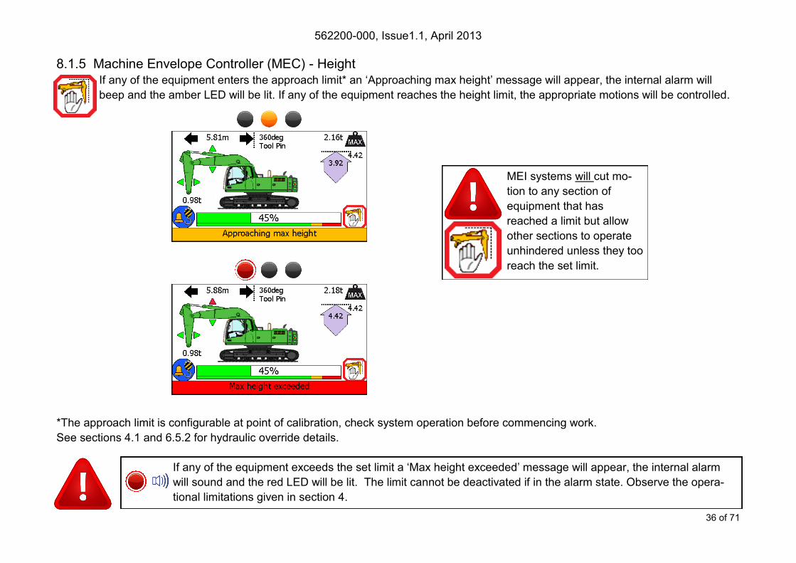
8.1.5 Machine Envelope Controller (MEC) - Height If any of the equipment enters the approach limit* an ‘Approaching max height’ message will appear, the internal alarm will
beep and the amber LED will be lit. If any of the equipment reaches the height limit, the appropriate motions will be controlled.
*The approach limit is configurable at point of calibration, check system operation before commencing work.
See sections 4.1 and 6.5.2 for hydraulic override details.
If any of the equipment exceeds the set limit a ‘Max height exceeded’ message will appear, the internal alarm
will sound and the red LED will be lit. The limit cannot be deactivated if in the alarm state. Observe the opera-
tional limitations given in section 4.
MEI systems will cut mo-
tion to any section of
equipment that has
reached a limit but allow
other sections to operate
unhindered unless they too
reach the set limit.

562200-000, Issue1.1, April 2013
37 of 71
8.2.1 Max Radius Limit
8.2.1 Max Radius Limit Menu
A max radius limit can be set by entering a known radius on the keypad or by manually moving the machine to
the desired limit.
Using the Max Radius Limits Menu, the max radius limit can be switched ON and OFF, a max radius limit can be set to a
known value, or the max radius limit can be set to the current farthest point.
See sections 8.2.2 to enter a known max radius and section 8.2.3 for setting the limit by moving the machine.
Once a max radius limit is set, the internal alarm will sound and the RED LED will light if the farthest point of the
equipment exceeds the current limit. Always check that the max radius limit activates at the set point. The limit
cannot be deactivated if in the alarm state. Observe the operational limitations given in section 4.
Enter a value
Exit to previous menu
Switches height monitoring
ON and OFF
Set limit using current far-
thest part of equipment
Current max radius limit. Only displayed
if a max radius limit is set.
562200-000, Issue1.1, April 2013
38 of 71
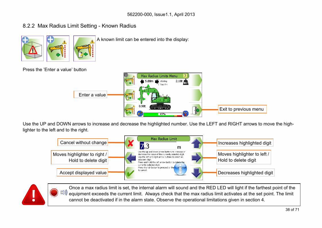
8.2.2 Max Radius Limit Setting - Known Radius
A known limit can be entered into the display:
Press the ’Enter a value’ button
Use the UP and DOWN arrows to increase and decrease the highlighted number. Use the LEFT and RIGHT arrows to move the high-
lighter to the left and to the right.
Once a max radius limit is set, the internal alarm will sound and the RED LED will light if the farthest point of the
equipment exceeds the current limit. Always check that the max radius limit activates at the set point. The limit
cannot be deactivated if in the alarm state. Observe the operational limitations given in section 4.
Increases highlighted digit
Decreases highlighted digit Accept displayed value
Cancel without change
Moves highlighter to left /
Hold to delete digit
Moves highlighter to right /
Hold to delete digit
Enter a value
Exit to previous menu

562200-000, Issue1.1, April 2013
39 of 71
To set the max radius limit using the machine, move
the equipment to the desired radius, and press the
‘current farthest point’ button. A confirmation box will
appear reporting the radius set. Press the TICK but-
ton to continue.
8.2.3 Max Radius Limit Setting - using Current Max Radius
Move equipment to required max
radius limit and press this button
Once a max radius limit is set, the internal alarm will sound and the RED LED will light if the farthest point of the
equipment exceeds the current limit. Always check that the max radius limit activates at the set point. The limit
cannot be deactivated if in the alarm state. Observe the operational limitations given in section 4.
562200-000, Issue1.1, April 2013
40 of 71
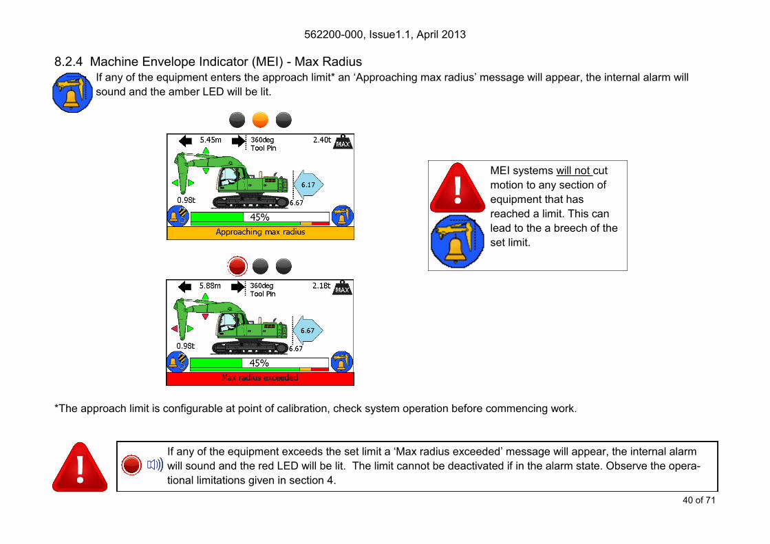
8.2.4 Machine Envelope Indicator (MEI) - Max Radius If any of the equipment enters the approach limit* an ‘Approaching max radius’ message will appear, the internal alarm will
sound and the amber LED will be lit.
*The approach limit is configurable at point of calibration, check system operation before commencing work.
If any of the equipment exceeds the set limit a ‘Max radius exceeded’ message will appear, the internal alarm
will sound and the red LED will be lit. The limit cannot be deactivated if in the alarm state. Observe the opera-
tional limitations given in section 4.
MEI systems will not cut
motion to any section of
equipment that has
reached a limit. This can
lead to the a breech of the
set limit.
562200-000, Issue1.1, April 2013
41 of 71
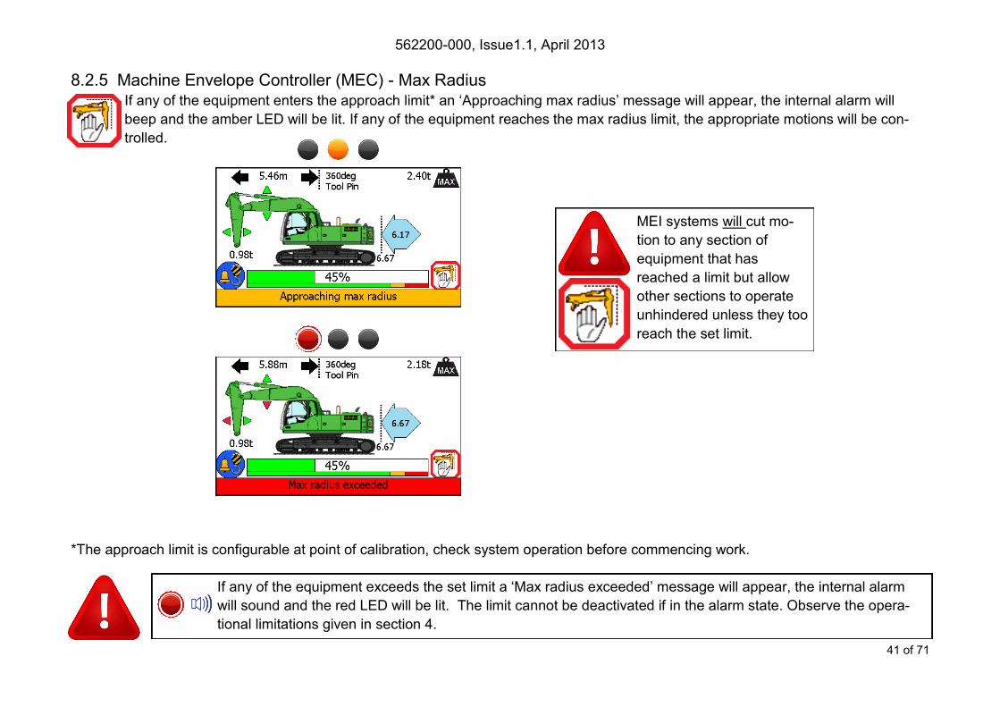
8.2.5 Machine Envelope Controller (MEC) - Max Radius If any of the equipment enters the approach limit* an ‘Approaching max radius’ message will appear, the internal alarm will
beep and the amber LED will be lit. If any of the equipment reaches the max radius limit, the appropriate motions will be con-
trolled.
*The approach limit is configurable at point of calibration, check system operation before commencing work.
If any of the equipment exceeds the set limit a ‘Max radius exceeded’ message will appear, the internal alarm
will sound and the red LED will be lit. The limit cannot be deactivated if in the alarm state. Observe the opera-
tional limitations given in section 4.
MEI systems will cut mo-
tion to any section of
equipment that has
reached a limit but allow
other sections to operate
unhindered unless they too
reach the set limit.
562200-000, Issue1.1, April 2013
42 of 71
8.3 Min Radius
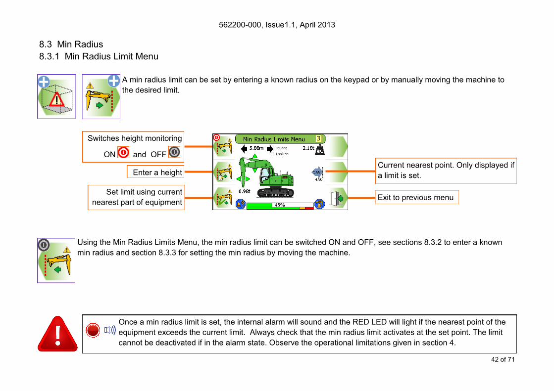
8.3.1 Min Radius Limit Menu
A min radius limit can be set by entering a known radius on the keypad or by manually moving the machine to
the desired limit.
Using the Min Radius Limits Menu, the min radius limit can be switched ON and OFF, see sections 8.3.2 to enter a known
min radius and section 8.3.3 for setting the min radius by moving the machine.
Once a min radius limit is set, the internal alarm will sound and the RED LED will light if the nearest point of the
equipment exceeds the current limit. Always check that the min radius limit activates at the set point. The limit
cannot be deactivated if in the alarm state. Observe the operational limitations given in section 4.
Enter a height
Exit to previous menu
Switches height monitoring
ON and OFF
Set limit using current
nearest part of equipment
Current nearest point. Only displayed if
a limit is set.

562200-000, Issue1.1, April 2013
43 of 71
8.3.2 Min Radius Limit Setting - Known Min Radius
A known min radius can be entered into the display:
Press the ’Enter a value’ button
Use the UP and DOWN arrows to increase and decrease the highlighted number. Use the LEFT and RIGHT arrows to move the high-
lighter to the left and to the right.
Increases highlighted digit
Decreases highlighted digit Accept displayed value
Cancel without change
Moves highlighter to left /
Hold to delete digit
Moves highlighter to right /
Hold to delete digit
Once a height limit is set, the internal alarm will sound and the RED LED will light if the nearest point of the
equipment exceeds the current limit. Always check that the min radius limit activates at the set point. The limit
cannot be deactivated if in the alarm state. Observe the operational limitations given in section 4.
Enter a value
Exit to previous menu

562200-000, Issue1.1, April 2013
44 of 71
To set the min radius limit using the machine, move
the equipment to the desired minimum radius, and
press the ‘current nearest point’ button. A confirma-
tion box will appear reporting the radius set. Press
the TICK button to continue.
8.3.3 Min Radius Limit Setting - using Current Min Radius
Move equipment to required min
radius limit and press this button
Once a height limit is set, the internal alarm will sound and the RED LED will light if the nearest point of the
equipment exceeds the current limit. Always check that the min radius limit activates at the set point. The limit
cannot be deactivated if in the alarm state. Observe the operational limitations given in section 4.
562200-000, Issue1.1, April 2013
45 of 71
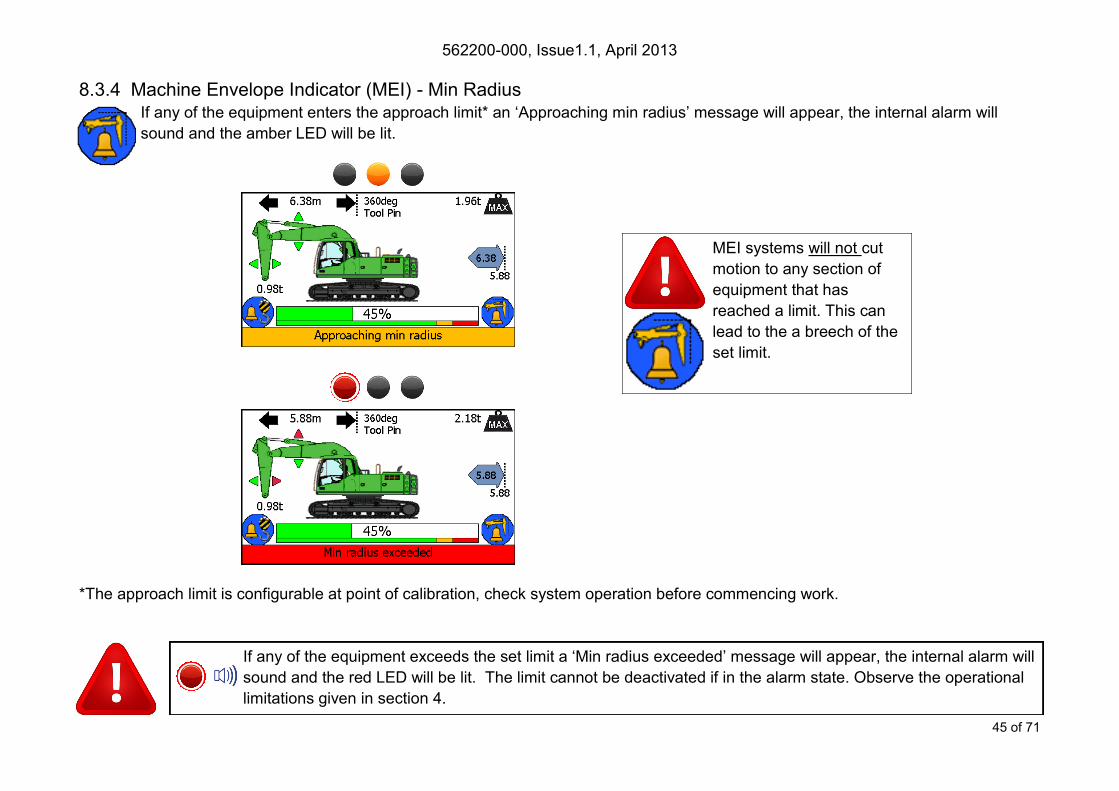
8.3.4 Machine Envelope Indicator (MEI) - Min Radius If any of the equipment enters the approach limit* an ‘Approaching min radius’ message will appear, the internal alarm will
sound and the amber LED will be lit.
*The approach limit is configurable at point of calibration, check system operation before commencing work.
If any of the equipment exceeds the set limit a ‘Min radius exceeded’ message will appear, the internal alarm will
sound and the red LED will be lit. The limit cannot be deactivated if in the alarm state. Observe the operational
limitations given in section 4.
MEI systems will not cut
motion to any section of
equipment that has
reached a limit. This can
lead to the a breech of the
set limit.
562200-000, Issue1.1, April 2013
46 of 71
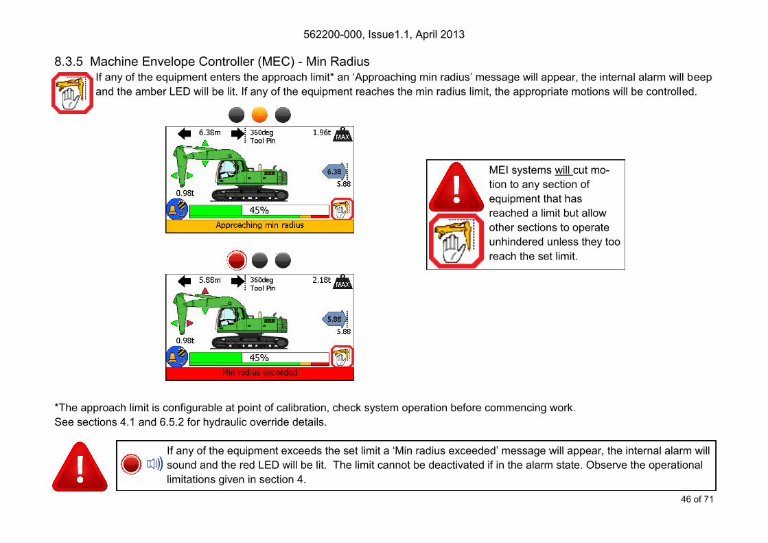
8.3.5 Machine Envelope Controller (MEC) - Min Radius If any of the equipment enters the approach limit* an ‘Approaching min radius’ message will appear, the internal alarm will beep
and the amber LED will be lit. If any of the equipment reaches the min radius limit, the appropriate motions will be controlled.
*The approach limit is configurable at point of calibration, check system operation before commencing work.
See sections 4.1 and 6.5.2 for hydraulic override details.
If any of the equipment exceeds the set limit a ‘Min radius exceeded’ message will appear, the internal alarm will
sound and the red LED will be lit. The limit cannot be deactivated if in the alarm state. Observe the operational
limitations given in section 4.
MEI systems will cut mo-
tion to any section of
equipment that has
reached a limit but allow
other sections to operate
unhindered unless they too
reach the set limit.
562200-000, Issue1.1, April 2013
47 of 71
Exit to previous menu
Enter a value
Set low limit using current
lowest part of equipment
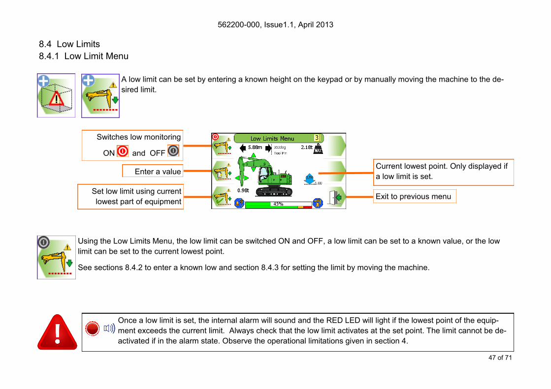
8.4 Low Limits
8.4.1 Low Limit Menu
A low limit can be set by entering a known height on the keypad or by manually moving the machine to the de-
sired limit.
Using the Low Limits Menu, the low limit can be switched ON and OFF, a low limit can be set to a known value, or the low
limit can be set to the current lowest point.
See sections 8.4.2 to enter a known low and section 8.4.3 for setting the limit by moving the machine.
Once a low limit is set, the internal alarm will sound and the RED LED will light if the lowest point of the equip-
ment exceeds the current limit. Always check that the low limit activates at the set point. The limit cannot be de-
activated if in the alarm state. Observe the operational limitations given in section 4.
Switches low monitoring
ON and OFF
Current lowest point. Only displayed if
a low limit is set.

562200-000, Issue1.1, April 2013
48 of 71
8.4.2 Low Limit Setting - Known Low
A known low limit can be entered into the display:
Press the ’Enter a value’ button
Use the UP and DOWN arrows to increase and decrease the highlighted number. Use the LEFT and RIGHT arrows to move the high-
lighter to the left and to the right.
Increases highlighted digit
Decreases highlighted digit Accept displayed value
Cancel without change
Moves highlighter to left /
Hold to delete digit
Moves highlighter to right /
Hold to delete digit
Once a low limit is set, the internal alarm will sound and the RED LED will light if the lowest point of the equip-
ment exceeds the current limit. Always check that the low limit activates at the set point. The limit cannot be de-
activated if in the alarm state. Observe the operational limitations given in section 4.
Enter a value
Exit to previous menu
562200-000, Issue1.1, April 2013
49 of 71
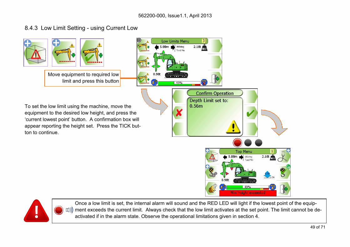
To set the low limit using the machine, move the
equipment to the desired low height, and press the
‘current lowest point’ button. A confirmation box will
appear reporting the height set. Press the TICK but-
ton to continue.
8.4.3 Low Limit Setting - using Current Low
Move equipment to required low
limit and press this button
Once a low limit is set, the internal alarm will sound and the RED LED will light if the lowest point of the equip-
ment exceeds the current limit. Always check that the low limit activates at the set point. The limit cannot be de-
activated if in the alarm state. Observe the operational limitations given in section 4.

562200-000, Issue1.1, April 2013
50 of 71
8.4.4 Machine Envelope Indicator (MEI) - Low If any of the equipment enters the approach limit* an ‘Approaching min height’ message will appear, the internal alarm will
sound and the amber LED will be lit.
*The approach limit is configurable at point of calibration, check system operation before commencing work.
If any of the equipment exceeds the set limit a ‘Min height exceeded’ message will appear, the internal alarm will
sound and the red LED will be lit. The limit cannot be deactivated if in the alarm state. Observe the operational
limitations given in section 4.
MEI systems will not cut
motion to any section of
equipment that has
reached a limit. This can
lead to the a breech of the
set limit.

562200-000, Issue1.1, April 2013
51 of 71
8.4.5 Machine Envelope Controller (MEC) - Low If any of the equipment enters the approach limit* an ‘Approaching min height’ message will appear, the internal alarm will beep
and the amber LED will be lit. If any of the equipment reaches the low limit, the appropriate motions will be controlled.
*The approach limit is configurable at point of calibration, check system operation before commencing work.
See sections 4.1 and 6.5.2 for hydraulic override details.
If any of the equipment exceeds the set limit a ‘Min height exceeded’ message will appear, the internal alarm will
sound and the red LED will be lit. The limit cannot be deactivated if in the alarm state. Observe the operational
limitations given in section 4.
MEI systems will cut mo-
tion to any section of
equipment that has
reached a limit but allow
other sections to operate
unhindered unless they too
reach the set limit.

562200-000, Issue1.1, April 2013
52 of 71
9 Warning Messages
9.1 On Screen Messages
*The approach limit is configurable at point of calibration, check system operation before commencing work.
PME continuously monitors the presence and condition of the safety controller and sensors. If the safety controller or any sensor fails an
error message box will appear at the bottom of the display. In the event of a failure, the cab mounted beacon (if fitted) will indicate that
the system is NOT active, the display red LED will flash and the internal and external alarms will sound.
Approaching max height Highest point of equipment within *0.5m of set limit
Maximum height exceeded Highest point of equipment has reached/exceeded set limit
Approaching max radius Furthest point of equipment within *0.5m of set limit
Maximum radius exceeded Furthest point of equipment has reached/exceeded set limit
Approaching min radius Nearest point of equipment within *0.5m of set limit
Minimumradius exceeded Nearest point of equipment has reached/exceeded set limit
Approaching min height Lowest point of equipment within *0.5m of set limit
Minimum height exceeded Lowest point of equipment has reached/exceeded set limit
Approaching SWL 95 percent of the maximum safe working load
Overload 105 percent of the maximum safe working load
Hydraulic Limit Pressure in the lift rams is in excess of 87% of main relief valve pressure
562200-000, Issue1.1, April 2013
53 of 71
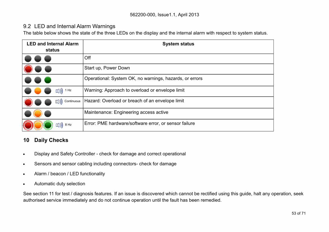
9.2 LED and Internal Alarm Warnings The table below shows the state of the three LEDs on the display and the internal alarm with respect to system status.
10 Daily Checks
Display and Safety Controller - check for damage and correct operational
Sensors and sensor cabling including connectors- check for damage
Alarm / beacon / LED functionality
Automatic duty selection
See section 11 for test / diagnosis features. If an issue is discovered which cannot be rectified using this guide, halt any operation, seek
authorised service immediately and do not continue operation until the fault has been remedied.
LED and Internal Alarm
status
System status
Off
Start up, Power Down
Operational: System OK, no warnings, hazards, or errors
Warning: Approach to overload or envelope limit
Hazard: Overload or breach of an envelope limit
Maintenance: Engineering access active
Error: PME hardware/software error, or sensor failure
1 Hz
Continuous
8 Hz
562200-000, Issue1.1, April 2013
54 of 71
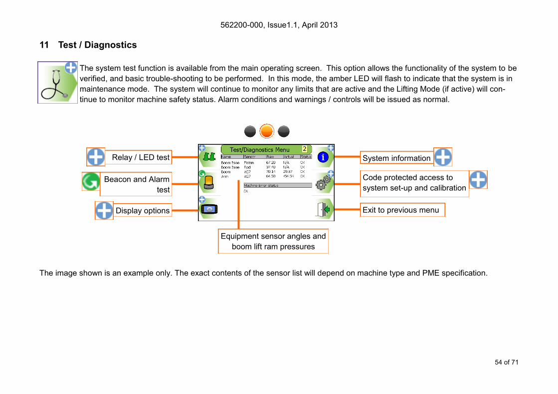
11 Test / Diagnostics
The system test function is available from the main operating screen. This option allows the functionality of the system to be
verified, and basic trouble-shooting to be performed. In this mode, the amber LED will flash to indicate that the system is in
maintenance mode. The system will continue to monitor any limits that are active and the Lifting Mode (if active) will con-
tinue to monitor machine safety status. Alarm conditions and warnings / controls will be issued as normal.
Relay / LED test System information
Beacon and Alarm
test
Display options
Code protected access to
system set-up and calibration
Exit to previous menu
Equipment sensor angles and
boom lift ram pressures
The image shown is an example only. The exact contents of the sensor list will depend on machine type and PME specification.
562200-000, Issue1.1, April 2013
55 of 71
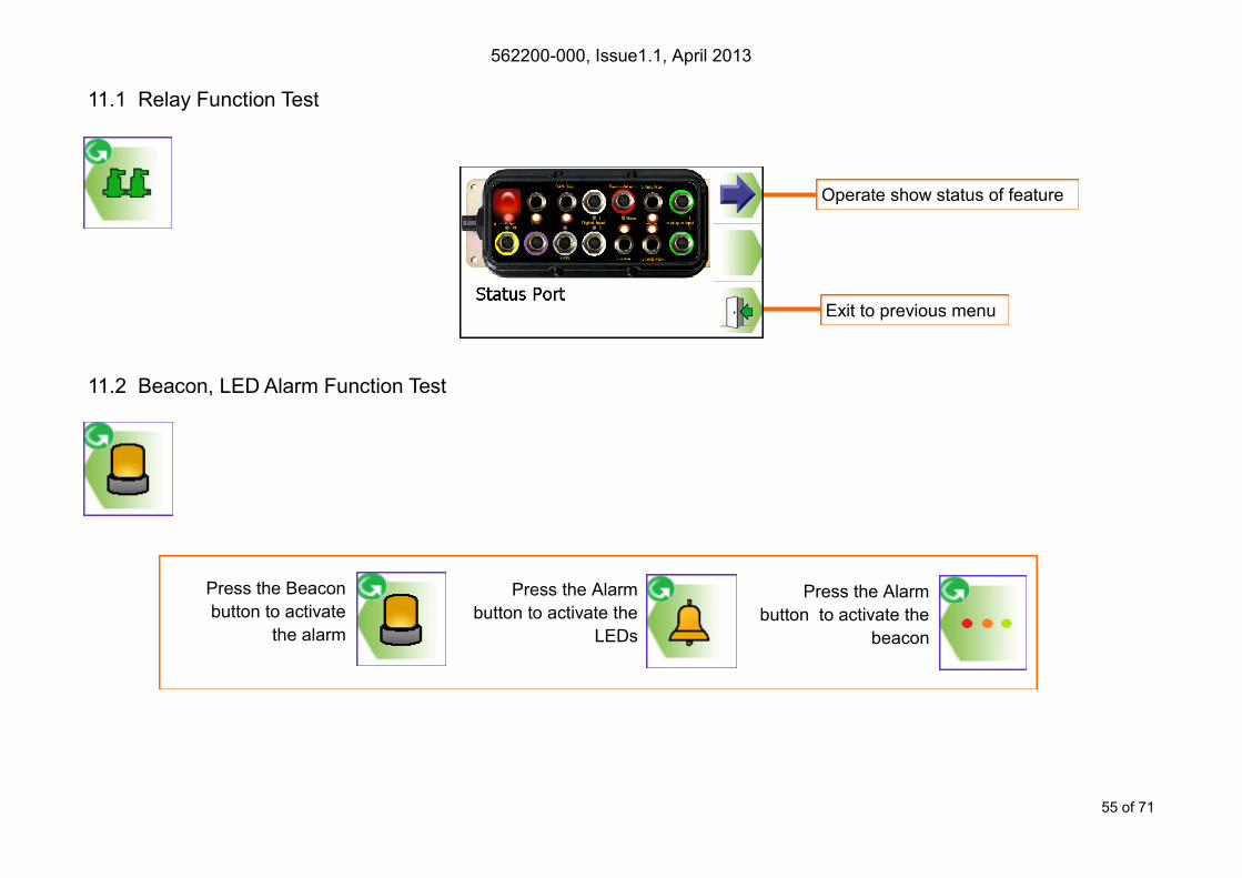
11.1 Relay Function Test
11.2 Beacon, LED Alarm Function Test
Press the Alarm
button to activate the
LEDs
Press the Alarm
button to activate the
beacon
Press the Beacon
button to activate
the alarm
Operate show status of feature
Exit to previous menu

562200-000, Issue1.1, April 2013
56 of 71
Alternative Lifting Mode screen
selection (See section 6.7)
Language selection
Exit to previous menu
12 Display Settings
The display brightness, button click volume, and the displayed machine colour and type can be adjusted from
this menu.
12.1 Day / Night Mode
To make viewing the display more comfortable at night, the display brightness can be switched to a
preset ‘night mode’. The system will default to day mode on power up.
Adjust button click volume
Select machine colour / type
Select day / night mode
ON OFF
Night mode ON
Reduced display
brightness
Select day / night mode:
Day mode ON
Full display brightness
562200-000, Issue1.1, April 2013
57 of 71
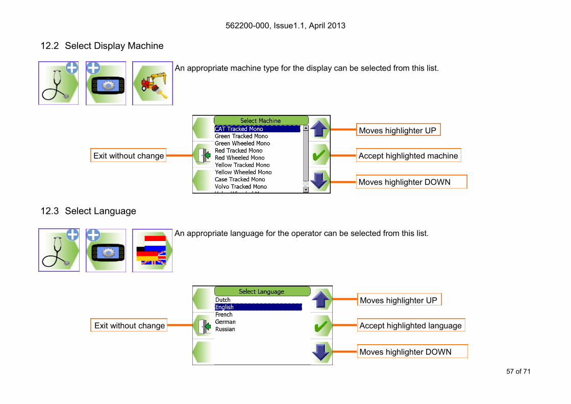
12.2 Select Display Machine
An appropriate machine type for the display can be selected from this list.
12.3 Select Language
An appropriate language for the operator can be selected from this list.
Moves highlighter UP
Exit without change
Moves highlighter DOWN
Accept highlighted machine
Moves highlighter UP
Exit without change
Moves highlighter DOWN
Accept highlighted language
562200-000, Issue1.1, April 2013
58 of 71
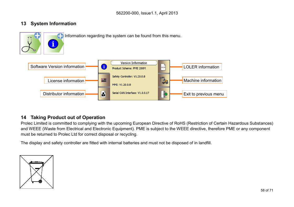
13 System Information
Information regarding the system can be found from this menu.
14 Taking Product out of Operation Prolec Limited is committed to complying with the upcoming European Directive of RoHS (Restriction of Certain Hazardous Substances)
and WEEE (Waste from Electrical and Electronic Equipment). PME is subject to the WEEE directive, therefore PME or any component
must be returned to Prolec Ltd for correct disposal or recycling.
The display and safety controller are fitted with internal batteries and must not be disposed of in landfill.
Software Version information
License information
Distributor information
LOLER information
Machine information
Exit to previous menu
562200-000, Issue1.1, April 2013
59 of 71
15 Service and Repair PME has very few user serviceable parts. The safety controller has internal fuses that, in the event of a blown fuse, can be replaced.
The service section describes daily, monthly and yearly checks that must be carried out to ensure safe operation of the system.
15.1 Maintenance Review Due to nature of the PME system operating environment, changes in usage can occur. Prolec Ltd must be notified of any changes in the
pattern of use of the system for consideration.
Any alterations or modifications to machine components which affect the system must be reported to Prolec Ltd or via the service agree-
ment holder.
To aid in the use of PME, all appropriate technical bulletins relating to PME are to be assessed and implemented as appropriate. This
information is available from Prolec Ltd.
Prolec Ltd must be informed of any Prolec system component failure via the service agreement holder.
Technical consultation is available to the user, contact Prolec Ltd or the service agreement holder.
Prolec Ltd Telephone +44 (0) 1202 681190
25 Benson Road Fax +44 (0) 1202 677909
Nuffield Industrial Estate Email [email protected]
Poole Dorset BH17 0GB

562200-000, Issue1.1, April 2013
60 of 71
15.2 Time / Date
The time and date can be checked in the alternative RCI screen number 2. Adjustment can be
made, see sections 16.2.1
15.2.1 Time / Date Adjustment
Time / date adjustment requires supervisor access rights.
Continued...
Adjust time
Adjust time zone Exit to previous menu
Adjust date

562200-000, Issue1.1, April 2013
61 of 71
15.2.1 Time / Date Adjustment continued
Moves highlighter UP
Cancel without change
Moves highlighter DOWN
Accept highlighted time zone
Increases highlighted digit
Decreases highlighted digit Accept displayed value
Cancel without change
Moves highlighter to left /
Hold to delete number
Moves highlighter to right /
Hold to delete digit
Increases highlighted digit
Decreases highlighted digit Accept displayed value
Cancel without change
Moves highlighter to left /
Hold to delete number
Moves highlighter to right /
Hold to delete digit
562200-000, Issue1.1, April 2013
62 of 71
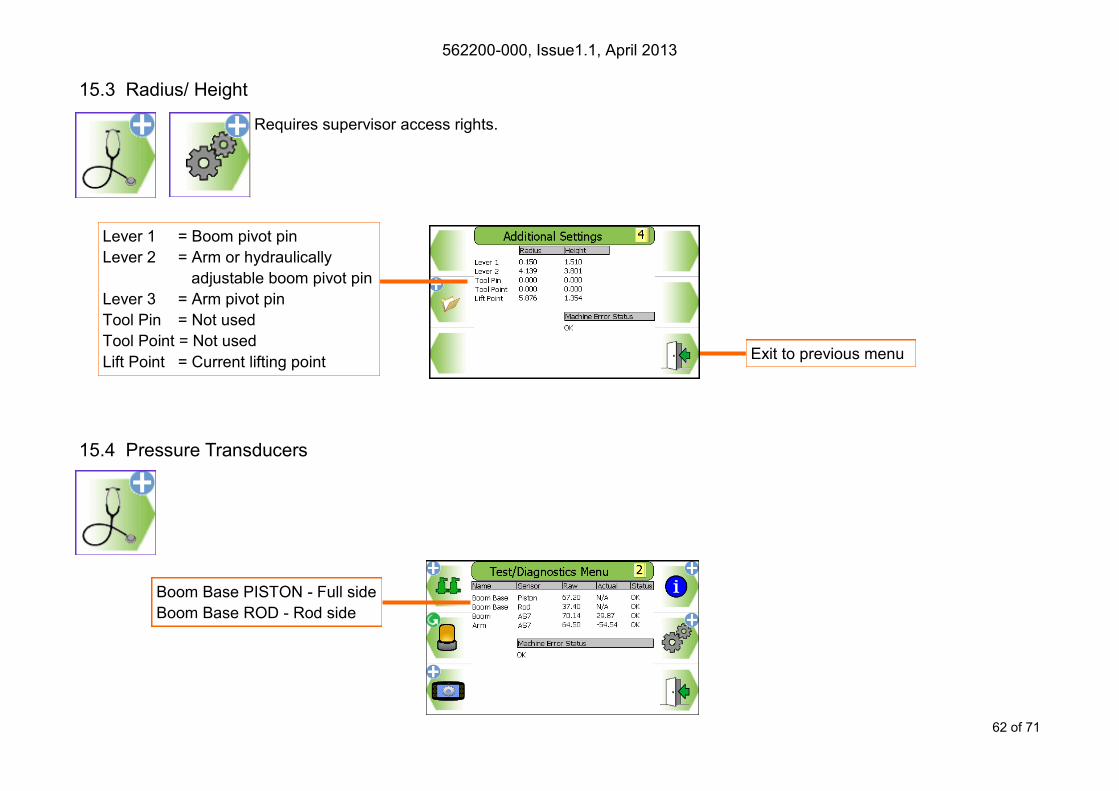
15.3 Radius/ Height
Requires supervisor access rights.
15.4 Pressure Transducers
Lever 1 = Boom pivot pin
Lever 2 = Arm or hydraulically
adjustable boom pivot pin
Lever 3 = Arm pivot pin
Tool Pin = Not used
Tool Point = Not used
Lift Point = Current lifting point Exit to previous menu
Boom Base PISTON - Full side
Boom Base ROD - Rod side
562200-000, Issue1.1, April 2013
63 of 71
15.5 Safe Working Load
1) SWL Display Check.
Set the machine at a near maximum radius, match a point on the load chart and check that the displayed SWL matches the load stated
on the load chart. This must be within+/- 5%. For triple articulated machines, the displayed SWL should be less than or equal to 5% of
the SWL on the ‘Max’ load chart, and greater than or equal to 5% of the SWL on the ‘Min’ load chart.
2) Alarm Check.
With the machine on level ground pull on a fixed point via a load cell or use a known weight. Confirm that the alarm sounds at the cor-
rect points for SWL approach and Overload.
In this example for a SWL of 2.11t : SWL Approach = 2.11 x 0.95 = 2.00 T
Overload = 2.11 x 1.05 = 2.22 T
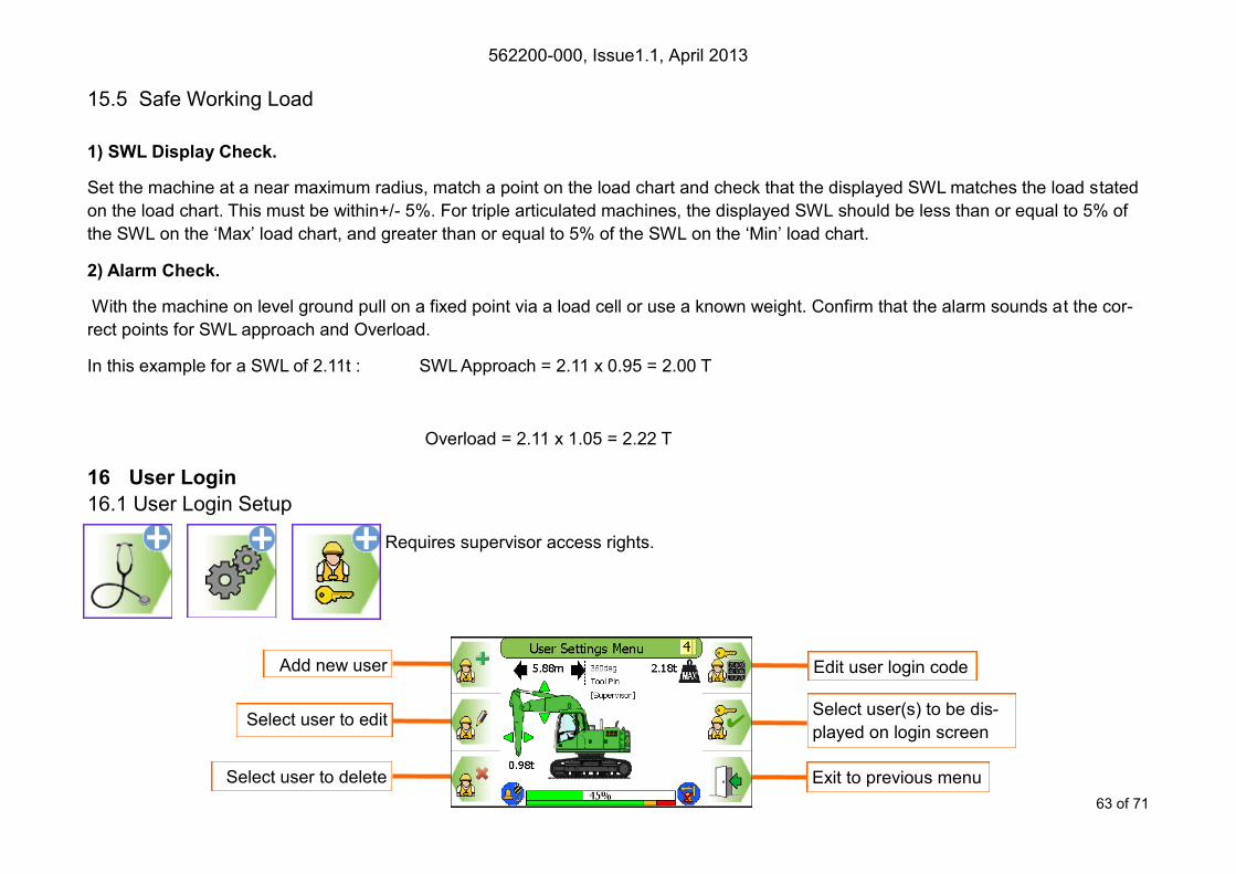
16 User Login
16.1 User Login Setup
Requires supervisor access rights.
Edit user login code
Exit to previous menu Select user to delete
Add new user
Select user(s) to be dis-
played on login screen Select user to edit

562200-000, Issue1.1, April 2013
64 of 71
16.2 Add New User
Requires supervisor access code
Moves highlighter UP
Exit without change
Moves highlighter DOWN
Select highlighted Privilege
Increases highlighted digit
Decreases highlighted digit Accept displayed value
Cancel without change
Moves highlighter to left /
Hold to delete number
Moves highlighter to right /
Hold to delete digit
Decreases highlighted number /
Scroll down though digits/ letters Accept displayed name
Toggle to / from keyboard
Moves highlighter to left Moves highlighter to right
Increases highlighted number /
Scroll up though digits/ letters
Highlight cross and press
tick to cancel without

562200-000, Issue1.1, April 2013
65 of 71
16.3 Edit User Details
Requires supervisor access rights.
Moves highlighter UP
Cancel without change
Moves highlighter DOWN
Select highlighted user
Increases highlighted digit
Decreases highlighted digit
Cancel without change
Moves highlighter to left /
Hold to delete digit
Moves highlighter to right /
Hold to delete digit
Moves highlighter UP
Return to previous screen
Moves highlighter DOWN
Select highlighted Privilege
Decreases highlighted number /
Scroll down though digits/ letters Accept displayed name
Toggle to / from keyboard
Moves highlighter to left Moves highlighter to right
Accept displayed value
Increases highlighted number /
Scroll up though digits/ letters
Highlight cross and press
tick to exit without change
562200-000, Issue1.1, April 2013
66 of 71
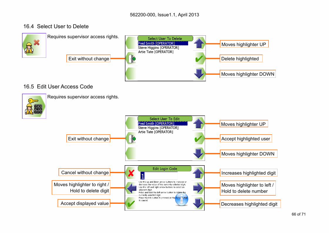
16.4 Select User to Delete
Requires supervisor access rights.
16.5 Edit User Access Code
Requires supervisor access rights.
Moves highlighter UP
Exit without change
Moves highlighter DOWN
Delete highlighted
Moves highlighter UP
Exit without change
Moves highlighter DOWN
Accept highlighted user
Increases highlighted digit
Decreases highlighted digit Accept displayed value
Cancel without change
Moves highlighter to left /
Hold to delete number
Moves highlighter to right /
Hold to delete digit
562200-000, Issue1.1, April 2013
67 of 71
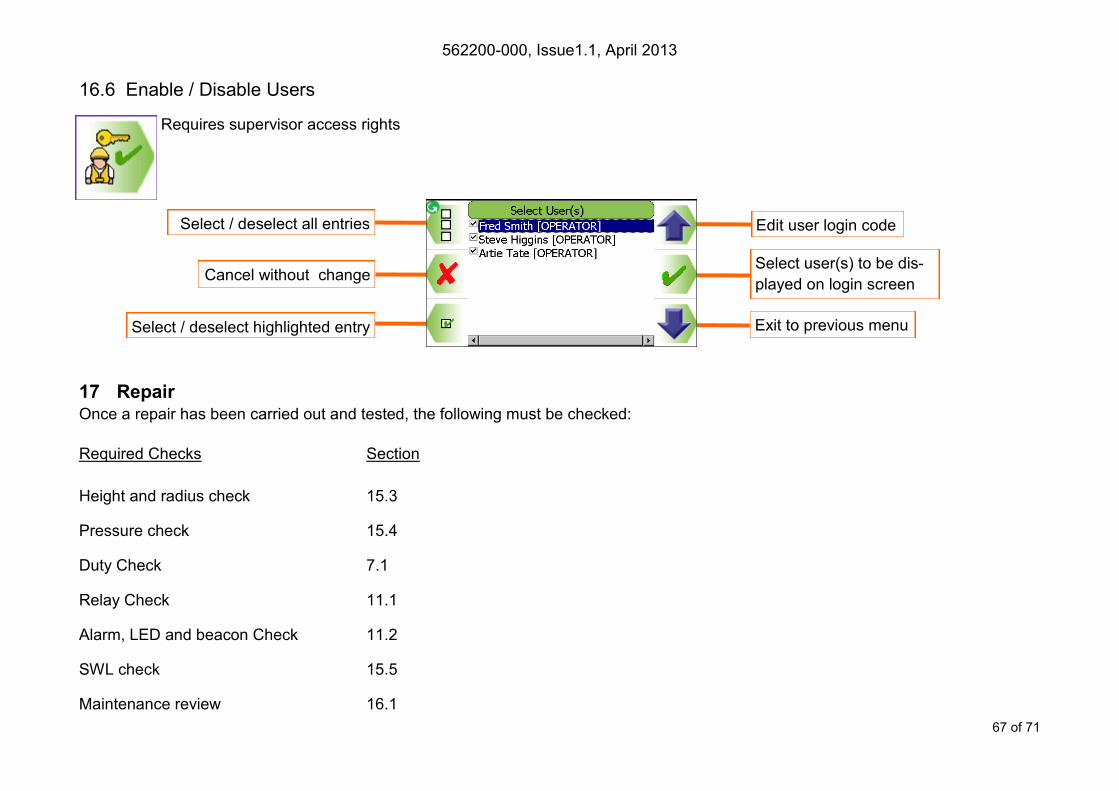
16.6 Enable / Disable Users
Requires supervisor access rights
17 Repair Once a repair has been carried out and tested, the following must be checked:
Edit user login code
Exit to previous menu
Select / deselect all entries
Select user(s) to be dis-
played on login screen Cancel without change
Select / deselect highlighted entry
Required Checks Section
Height and radius check 15.3
Pressure check 15.4
Duty Check 7.1
Relay Check 11.1
Alarm, LED and beacon Check 11.2
SWL check 15.5
Maintenance review 16.1

562200-000, Issue1.1, April 2013
68 of 71
18 Definitions / Glossary continued
Definitions of words used to ensure understanding
SWL Safe Working Load
LOH Load on Hook
Duty Lifting configuration
Tip A tip is defined as: Idler rollers off the track (over the side), or rear idler rollers off the track when over the
front on tracked machines and a tyre is clear of the ground on wheeled machines.
Hydraulic Limit Maximum SWL limited by 87% of maximum hydraulic capacity rather than machine stability.
Pitch Longitudinal base machine angle (fore / aft)
Roll Lateral base machine angle (side to side)
Boom First articulation connected to turret
Arm Second articulation
Artic Second articulation of a hydraulically adjustable boom (luffing boom, knuckle boom, two piece boom)
Turret Section of machine above the undercarriage
Undercarriage Section which the tracks/wheels attach too
Track continuous band of treads, metal or rubber covered
Blade heavy metal plate on the front of the machine, used for stability and moving material
Stabiliser Hydraulically powered arms that can be lowered and raised to increase the Stability of the machine
Counterweight Weight attached to the rear of an excavator to increase digging force and lifting capacity
Pivot pin Point at which the articulations rotate about
Wheeled excavator An excavator fitted with wheels
Tracked excavator An excavator fitted with tracks, also known as
Bucket Digging attachment
Attachment Tool fixed to the dipper other than a bucket
Pressure transducer Device to measure pressure within an hydraulic cylinder Full side Internal section below the cylinder rod face
Rod side Internal section above the cylinder rod face
562200-000, Issue1.1, April 2013
69 of 71
19 Definitions / Glossary
Relay Electronic device to operate motion cut valve
SC Safety Controller
MMI Man Machine Interface (i.e. Display)
CAN cable Cable connecting system components
Angle sensor Sensor detecting current equipment angle
Motion Cut Direct control of component hydraulic service
Power Supply DC supply voltage
Ram Hydraulic Cylinder
P/N Part Number


562200-000, Issue1.1, April 2013
Prolec Ltd
25 Benson Road
Nuffield Industrial Estate
Poole
England
BH17 0GB
Tel: +44 (0)1202 681190
E-mail: [email protected]
Prolec Ltd® is a James Fisher Company