OPERATOR’S MANUAL - Bush Hog … · This Operator's Manual is an integral part of the safe...
60
© 2014 Alamo Group Inc. PHDHF SERIES PHDHC SERIES PHDHF, PHDHF20, PHDHF30 PHDHC20, PHDHC30, PHDHC35 Published 07/14 Part No. 50074550 OPERATOR’S MANUAL BUSH HOG ® 2501 Griffin Ave. Selma, AL 36703 334-874-2700 www.bushhog.com HYDRAULIC PLANETARY DRIVE DIGGER This Operator's Manual is an integral part of the safe operation of this machine and must be maintained with the unit at all times. READ, UNDERSTAND, and FOLLOW the Safety and Operation Instructions contained in this manual before operating the equipment. C01- Cover $0.00
Transcript of OPERATOR’S MANUAL - Bush Hog … · This Operator's Manual is an integral part of the safe...

© 2014 Alamo Group Inc.
PHDHF SERIES PHDHC SERIES
PHDHF, PHDHF20, PHDHF30PHDHC20, PHDHC30, PHDHC35
Published 07/14 Part No. 50074550
OPERATOR’S MANUAL
BUSH HOG®
2501 Griffin Ave. Selma, AL 36703334-874-2700www.bushhog.com
HYDRAULIC PLANETARYDRIVE DIGGER
This Operator's Manual is an integral part of the safe operation of this machine and mustbe maintained with the unit at all times. READ, UNDERSTAND, and FOLLOW the Safetyand Operation Instructions contained in this manual before operating the equipment. C01-Cover
$0.00

To the Owner/Operator/Dealer
All implements with moving parts are potentially hazardous. There is no substitute for a cautious, safe-mindedoperator who recognizes the potential hazards and follows reasonable safety practices. The manufacturer hasdesigned this implement to be used with all its safety equipment properly attached to minimize the chance ofaccidents.
BEFORE YOU START! Read the safety messages on the implement and shown in your manual. Observe the rulesof safety and common sense!
WARRANTY INFORMATION:
Read and understand the complete Warranty Statement found in this Manual. Fill out the Warranty RegistrationForm in full and return it to within 30 Days. Make certain the Serial Number of the Machine is recorded on theWarranty Card and on the Warranty Form that you retain

TABLE OF CONTENTS
SAFETY SECTION .............................................................................................................. 1-1
General Safety Instructions and Practices .........................................................................................................1-2Operator Safety Instructions and Practices .......................................................................................................1-3Equipment Operation Safety Instructions and Practices ....................................................................................1-6Connecting or Disconnecting Implement Safety Instructions and Practices ......................................................1-8Transporting Safety Instructions and Practices .................................................................................................1-8Maintenance and Service Safety Instructions and Practices .............................................................................1-9Storage and Parking Safety Instructions and Practices ...................................................................................1-11Concluding Safety Instructions and Practices ..................................................................................................1-11Decal Location - PHDHF Series ......................................................................................................................1-12Decal Location - PHDHC Series ......................................................................................................................1-13Decal Location PHDHF, PHDHC Skid Steer Mounts .......................................................................................1-14Decal Description .............................................................................................................................................1-15Federal Laws and Regulations ........................................................................................................................1-17
INTRODUCTION SECTION ................................................................................................. 2-1
ASSEMBLY SECTION ........................................................................................................ 3-1
LOADER BUCKET HITCH MOUNT ASSEMBLY ..............................................................................................3-2SKID STEER HITCH ASSEMBLY .....................................................................................................................3-2ATTACHING AUGER TO GEARBOX OUTPUT SHAFT ...................................................................................3-3ATTACHING DRIVE MOTOR TO HITCH MOUNT ............................................................................................3-3BACKHOE HYDRAULIC DRILL UNIT ...............................................................................................................3-3
OPERATION SECTION ....................................................................................................... 4-1
Standard Equipment and Specifications ............................................................................................................4-3OPERATOR REQUIREMENTS .........................................................................................................................4-4POWER UNIT REQUIREMENTS ......................................................................................................................4-5ROPS and Seat Belt ..........................................................................................................................................4-5Power Unit Safety Devices ................................................................................................................................4-6Auxiliary Hydraulics ............................................................................................................................................4-6GETTING ON AND OFF THE POWER UNIT ....................................................................................................4-6Boarding the Power Unit ....................................................................................................................................4-7Dismounting the Power Unit ..............................................................................................................................4-7STARTING THE POWER UNIT .........................................................................................................................4-8PRE-OPERATION INSPECTION AND SERVICE .............................................................................................4-8Power Unit Pre-Operation Inspection/Service ...................................................................................................4-9Digger Pre-Operation Inspection/Service ........................................................................................................4-10OPERATING THE POWER UNIT AND IMPLEMENT .....................................................................................4-12Digger Operating Instructions ..........................................................................................................................4-13Auger Selection Based on Drilling Application .................................................................................................4-14IMPLEMENT STORAGE .................................................................................................................................4-15TRANSPORTING THE POWER UNIT AND IMPLEMENT ..............................................................................4-15Transporting on Public Roadways ...................................................................................................................4-16Hauling the Power Unit and Implement ...........................................................................................................4-18TROUBLESHOOTING GUIDE ........................................................................................................................4-19
MAINTENANCE SECTION .................................................................................................. 5-1
LUBRICATION INFORMATION .........................................................................................................................5-2AUGER MAINTENANCE ...................................................................................................................................5-3MACHINE INSPECTION ...................................................................................................................................5-3STORAGE .........................................................................................................................................................5-3HYDRAULIC LINES, COUPLERS & ADAPTERS .............................................................................................5-4PROPER TORQUE FOR FASTENERS ............................................................................................................5-4

LIMITED WARRANTY for PHDHF Models
Bush Hog warrants to the original purchaser of any new Bush Hog PHDHF, purchased from an authorized BushHog dealer, that the equipment be free from defects in material and workmanship for a period of two (2) years fornon-commercial, state and municipalities’ use and ninety (90) days for commercial use from date of retail sale. Theobligation of Bush Hog to the purchaser under this warranty is limited to the repair or replacement of defectiveparts.
Replacement or repair parts installed in the equipment covered by this limited warranty are warranted for ninety(90) days from the date of purchase of such part or to the expiration of the applicable new equipment warrantyperiod, whichever occurs later. Warranted parts shall be provided at no cost to the user at an authorized Bush Hogdealer during regular working hours. Bush Hog reserves the right to inspect any equipment or parts which areclaimed to have been defective in material or workmanship.
NOTICE: Bush Hog is NOT responsible for damage to augers caused by hitting underground objects (rocks, roots,etc.) or for bent augers caused by moving the tractor with the auger in the ground.
DISCLAIMER OF IMPLIED WARRANTIES & CONSEQUENTIAL DAMAGESBush Hog’s obligation under this limited warranty, to the extent allowed by law, is in lieu of all warranties, implied orexpressed, INCLUDING IMPLIED WARRANTIES OF MERCHANTABILITY AND FITNESS FOR A PARTICULARPURPOSE and any liability for incidental and consequential damages with respect to the sale or use of the itemswarranted. Such incidental and consequential damages shall include but not be limited to: transportation chargesother than normal freight charges; cost of installation other than cost approved by Bush Hog; duty; taxes; chargesfor normal service or adjustment; loss of crops or any other loss of income; rental of substitute equipment,expenses due to loss, damage, detention or delay in the delivery of equipment or parts resulting from acts beyondthe control of Bush Hog.
THIS LIMITED WARRANTY SHALL NOT APPLY:1. To vendor items which carry their own warranties, such as engines, tires, and tubes.
2. If the unit has been subjected to misapplication, abuse, misuse, negligence, fire or other accident.
3. If parts not made or supplied by Bush Hog have been used in connection with the unit, if, in the sole judgementof Bush Hog such use affects its performance, stability or reliability.
4. If the unit has been altered or repaired outside of an authorized Bush Hog dealership in a manner which, in thesole judgement of Bush Hog, affects its performance, stability or reliability.
5. To normal maintenance service and normal replacement items such as gearbox lubricant, hydraulic fluid, wornblades, or to normal deterioration of such things as belts and exterior finish due to use or exposure.
6. To expendable or wear items such as teeth, chains, sprockets, belts, springs and any other items that in thecompany’s sole judgement is a wear item.
NO EMPLOYEE OR REPRESENTATIVE OF BUSH HOG IS AUTHORIZED TO CHANGE THIS LIMITEDWARRANTY IN ANY WAY OR GRANT ANY OTHER WARRANTY UNLESS SUCH CHANGE IS MADE INWRITING AND SIGNED BY BUSH HOG’S SERVICE MANAGER, 2501 GRIFFIN AVE., SELMA, ALABAMA36703.
Record the model number, serial number and date
purchased. This information will be helpful to your
dealer if parts or service are required.
MAKE CERTAIN THE WARRANTY
HAS BEEN FILED WITH BUSH HOG
SELMA, ALABAMA
MODEL NUMBER ________________________________
SERIAL NUMBER ________________________________
DATE OF RETAIL SALE ___________________________

LIMITED WARRANTY for PHDHC Models
Bush Hog warrants to the original purchaser of any new Bush Hog PHDHC, purchased from an authorized BushHog dealer, that the equipment be free from defects in material and workmanship for a period of two (2) years fullcoverage and five (5) years parts only for nob-commercial and commercial use from date of retail sale. Theobligation of Bush Hog to the purchaser under this warranty is limited to the repair or replacement of defectiveparts.
Replacement or repair parts installed in the equipment covered by this limited warranty are warranted for ninety(90) days from the date of purchase of such part or to the expiration of the applicable new equipment warrantyperiod, whichever occurs later. Warranted parts shall be provided at no cost to the user at an authorized Bush Hogdealer during regular working hours. Bush Hog reserves the right to inspect any equipment or parts which areclaimed to have been defective in material or workmanship.
NOTICE: Bush Hog is NOT responsible for damage to augers caused by hitting underground objects (rocks, roots,etc.) or for bent augers caused by moving the tractor with the auger in the ground.
DISCLAIMER OF IMPLIED WARRANTIES & CONSEQUENTIAL DAMAGESBush Hog’s obligation under this limited warranty, to the extent allowed by law, is in lieu of all warranties, implied orexpressed, INCLUDING IMPLIED WARRANTIES OF MERCHANTABILITY AND FITNESS FOR A PARTICULARPURPOSE and any liability for incidental and consequential damages with respect to the sale or use of the itemswarranted. Such incidental and consequential damages shall include but not be limited to: transportation chargesother than normal freight charges; cost of installation other than cost approved by Bush Hog; duty; taxes; chargesfor normal service or adjustment; loss of crops or any other loss of income; rental of substitute equipment,expenses due to loss, damage, detention or delay in the delivery of equipment or parts resulting from acts beyondthe control of Bush Hog.
THIS LIMITED WARRANTY SHALL NOT APPLY:7. To vendor items which carry their own warranties, such as engines, tires, and tubes.
8. If the unit has been subjected to misapplication, abuse, misuse, negligence, fire or other accident.
9. If parts not made or supplied by Bush Hog have been used in connection with the unit, if, in the sole judgementof Bush Hog such use affects its performance, stability or reliability.
10.If the unit has been altered or repaired outside of an authorized Bush Hog dealership in a manner which, in thesole judgement of Bush Hog, affects its performance, stability or reliability.
11.To normal maintenance service and normal replacement items such as gearbox lubricant, hydraulic fluid, wornblades, or to normal deterioration of such things as belts and exterior finish due to use or exposure.
12.To expendable or wear items such as teeth, chains, sprockets, belts, springs and any other items that in thecompany’s sole judgement is a wear item.
NO EMPLOYEE OR REPRESENTATIVE OF BUSH HOG IS AUTHORIZED TO CHANGE THIS LIMITEDWARRANTY IN ANY WAY OR GRANT ANY OTHER WARRANTY UNLESS SUCH CHANGE IS MADE INWRITING AND SIGNED BY BUSH HOG’S SERVICE MANAGER, 2501 GRIFFIN AVE., SELMA, ALABAMA36703.
Record the model number, serial number and date
purchased. This information will be helpful to your
dealer if parts or service are required.
MAKE CERTAIN THE WARRANTY
HAS BEEN FILED WITH BUSH HOG
SELMA, ALABAMA
MODEL NUMBER ________________________________
SERIAL NUMBER ________________________________
DATE OF RETAIL SALE ___________________________


Safety Section 1-1
SAFETY SECTION

SAFETYS
AF
ET
Y
General Safety Instructions and PracticesA careful operator is the best operator. Safety is of primary importance to the manufacturer and should be tothe owner/operator. Most accidents can be avoided by being aware of your equipment, your surroundings, andobserving certain precautions. The first section of this manual includes a list of Safety Messages that, iffollowed, will help protect the operator and bystanders from injury or death. Read and understand these SafetyMessages before assembling, operating or servicing this Implement. This equipment should only be operatedby those persons who have read the manual, who are responsible and trained, and who know how to do soresponsibly.
The Safety Alert Symbol combined with a Signal Word, as seen below, is used throughout thismanual and on decals which are attached to the equipment. The Safety Alert Symbol means:“ATTENTION! BECOME ALERT! YOUR SAFETY IS INVOLVED!” The Symbol and Signal Wordare intended to warn the owner/operator of impending hazards and the degree of possible injuryfaced when operating this equipment.
Indicates an imminently hazardous situation that, if not avoided, WILL result in DEATH ORVERY SERIOUS INJURY.
Indicates an imminently hazardous situation that, if not avoided, COULD result in DEATHOR SERIOUS INJURY.
Indicates an imminently hazardous situation that, if not avoided, MAY result in MINORINJURY.
Identifies special instructions or procedures that, if not strictly observed, could result indamage to, or destruction of the machine, attachments or the environment.
NOTE: Identifies points of particular interest for more efficient and convenient operation or repair.(SG-1)
Practice all usual and customary safe working precautions and above all---remember safety isup to YOU. Only YOU can prevent serious injury or death from unsafe practices.
READ, UNDERSTAND, and FOLLOW the following Safety Messages. Serious injury ordeath may occur unless care is taken to follow the warnings and instructions stated in theSafety Messages. Always use good common sense to avoid hazards. (SG-2)
Si no lee ingles, pida ayuda a alguien que si lo lea para que le traduzca lasmedidas de seguridad. (SG-3)
PHDHF / PHDHC 07/14 Safety Section 1-2
© 2014 Alamo Group Inc.

SAFETYS
AF
ET
Y
Operator Safety Instructions and Practices
Engine Exhaust, some of its constituents, and certain vehicle components contain or emitchemicals known to the state of California to cause cancer and birth defects or otherreproductive harm. (SG-30)
Battery posts, terminals and related accessories contain lead and lead compounds,chemicals known to the state of California to cause cancer, birth defects or otherreproductive harm. (SG-31)
Never crawl under a raised Implement supported solely by the Power Unit boom. Releaseof the control lever or mechanical failure will result in the Implement falling and possibleinjury or death. Always securely block up the Implement before crawling underneath to
perform repairs and service. (SPU-33)
Never operate the Power Unit or Implement until you have read andcompletely understand this Manual, the Power Unit Operator’s Manual,and each of the Safety Messages found in the Manual or on the Power
Unit and Implement. Learn how to stop the Power Unit engine suddenlyin an emergency. Never allow inexperienced or untrained personnel toooperate the Power Unit and Implement without supervision. Make surethe operator has fully read and understood the manuals prior tooperation. (SPU-36)
Always maintain the safety signs in good readable condition. If the safety signs are missing,damaged, or unreadable, obtain and install replacement safety signs immediately. (SG-5)
The operator and all support personnel should wear hard hats, safetyshoes, safety glasses, and proper hearing protection at all times forprotection from injury including injury from items that may be thrown bythe equipment. (SG-16)
PHDHF / PHDHC 07/14 Safety Section 1-3
© 2014 Alamo Group Inc.

SAFETYS
AF
ET
Y
PROLONGED EXPOSURE TO LOUD NOISE MAY CAUSEPERMANENT HEARING LOSS! Tractors with or without an Implementattached can often be noisy enough to cause permanent hearing loss.We recommend that you always wear hearing protection if the noise inthe Operator’s position exceeds 80db. Noise over 85db over anextended period of time will cause severe hearing loss. Noise over 90dbadjacent to the Operator over an extended period of time will causepermanent or total hearing loss. NOTE: Hearing loss from loud noise[from tractors, chain saws, radios, and other such sources close to theear] is cumulative over a lifetime without hope of natural recovery. (SG-I7)
Always read carefully and comply fully with the manufacturer’sinstructions when handling oil, solvents, cleansers, and any otherchemical agent. (SG-22)
Never run the Power Unit engine in a closed building or without adequate ventilation. Theexhaust fumes can be hazardous to your health. (SPU-23)
KEEP AWAY FROM ROTATING ELEMENTS to prevent entanglement
and possible serious injury or death. (SPHD-2)
NEVER put hands on the Post Hole Digger Auger, Gearbox, or Boom to locate the Augerwhen there is any sign of rotation of the Driveline or Auger. Post Hole Diggers areoperated by one person from the tractor seat. Keep all bystanders and/or coworkers awayfrom the Post Hole Digger. (SPHD-4)
Never use body weight to try to push Auger into the ground to prevent entanglement andpossible serious injury or death. (See Operating Instructions for advice on drilling in hardground or rocky conditions.) (SPHD-8)
There are obvious and hidden potential hazards in the operation of this Post Hole Digger.REMEMBER! This machine can be operated on hillsides and slopes and in other rough
conditions which require increased care and increased awareness of the potential hazardson both the operator’s and any bystander's part. Serious injury or even death may occurunless care is taken to insure the safety of the operator, helpers, and any bystanders. (SPHD-11)
PHDHF / PHDHC 07/14 Safety Section 1-4
© 2014 Alamo Group Inc.

SAFETYS
AF
ET
Y
Always keep a careful lookout and use extreme care when working around overheadobstructions. Never allow the Auger within 10 feet of any power line. When working close
to overhead power lines exercise caution and consult your electric company for a safe codeof operation. (SPHD-13)
Dig holes only while seated in the Operator’s seat with the seatbelt securely fastened.Keep all other persons a minimum distance of 10 feet away from the Tractor and Digger.Always engage the Tractor parking brakes and set the transmission in park when operating
the digger. (SPHD-14)
Never allow children to play on or around Power Unit or Implement. Children can slip or fall
off the Equipment and be injured or killed. Children can cause the Implement to shift or fall
crushing themselves or others. (SPU-24)
NEVER use drugs or alcohol immediately before or while operating thePower Unit and Implement. Drugs and alcohol will affect an operator’salertness and coordination and therefore affect the operator’s ability to
operate the equipment safely. Before operating the Power Unit or Implement,an operator on prescription or over-the-counter medication must consult amedical professional regarding any side effects of the medication that wouldhinder their ability to operate the Equipment safely. NEVER knowingly allowanyone to operate this equipment when their alertness or coordination isimpaired. Serious injury or death to the operator or others could result if theoperator is under the influnce of drugs or alcohol. (SPU-25)
Prolonged operation may cause operator boredom and fatigue affecting safe operation.Take scheduled work breaks to help prevent these potentially impaired operatingconditions. Never operate the Implement and Tractor in a fatigued or bored mental statewhich impairs proper and safe operation. (SG-32)
Use extreme caution when getting onto the Implement to perform repairs, maintenance andwhen removing accumulated material. Only stand on solid flat surfaces to ensure goodfooting. Use a ladder or raised stand to access high spots which cannot be reached fromground level. Slipping and falling can cause serious injury or death. (SG-33)
Avoid contact with hot surfaces including hydraulic oil tanks, pumps, motors, valves andhose connections. Relieve hydraulic pressure before performing maintenance or repairs.Use gloves and eye protection when servicing hot components. Contact with a hot surfaceor fluid can cause serious injury from burns or scalding. (SG-34)
Avoid contact with hot surfaces of the engine or muffler. Use gloves and eye protectionwhen servicing hot components. Contact with a hot surface or fluid can cause serious injuryfrom burns or scalding. (SG-38)
PHDHF / PHDHC 07/14 Safety Section 1-5
© 2014 Alamo Group Inc.

SAFETYS
AF
ET
Y
Equipment Operation Safety Instructions and Practices
Do not operate the implement while wearing loose fitting clothing. Entanglement of theclothing with the rotating elements can result in serious injury or even death. Stay clear ofall rotating elements at all times. (SSP-03)
Never leave the Tractor and Implement unattended while the Implement is in the liftedposition. Accidental operation of lifting lever or a hydraulic failure may cause sudden dropof unit with injury or death by crushing. To properly park the implement when disconnectingit from the tractor, lower the stand and put the retaining pin securely in place, or put a securesupport under the A-Frame. Lower the implement carefully to the ground. Do not put handsor feet under lifted components. (S3PT-1)
Be sure you have adequate knowledge of the property you will be working on. Take time tomake yourself aware of any area underwater or underground lines or cables. Contact withburied lines or cable could result in serious injury or death. (STL-1)
Operate this Equipment only with a Power Unit equipped with anapproved operator Roll-Over Protective Structure (ROPS). Alwayswear seat belts. Serious injury or even death could result from fallingoff the Power Unit--particularly during a turnover when the operatorcould be pinned under the Operator Protective Structure. (SPU-14)
BEFORE leaving the Power Unit seat, always engage the brake and set the Power Unittransmission in parking gear, disengage the auxiliary hydraulics, stop the engine, removethe key, and wait for all moving parts to stop. Place the Power Unit shift lever into a lowrange or parking gear to prevent the tractor from rolling. Never dismount a Power Unit thatis moving or while the engine is running. Operate the Power Unit controls from theoperator seat only. (SPU-15)
Never allow children to operate or ride on the Power Unit or Implement.(SPU-17)
PHDHF / PHDHC 07/14 Safety Section 1-6
© 2014 Alamo Group Inc.

SAFETYS
AF
ET
Y
Never allow children to operate, ride on, or come close to the Tractor orImplement. Usually, 16-17 year-old children who are mature andresponsible can operate the implement with adult supervision, if theyhave read and understand the Operator’s Manuals, been trained inproper operation of the tractor and Implement, and are physically largeenough to reach and operate the controls easily. (SG-11)
Do not mount the Power Unit while the Power Unit is moving. Mount thePower Unit only when the Power Unit and all moving parts arecompletely stopped. (SPU-18)
Start the Power Unit only when properly seated in the Power Unit seat. Startinga Power Unit in gear can result in injury or death. Read the Power UnitOperator’s Manual for proper starting instructions. (SPU-19)
Operate this Equipment only with a Power Unit equipped with anapproved operator Roll-Over Protective Structure (ROPS). Alwayswear seat belts. Serious injury or even death could result from fallingoff the Power Unit--particularly during a turnover when the operatorcould be pinned under the Operator Protective Structure. (SPU-14)
Do not operate this Equipment with hydraulic oil or fuel leaking. Oiland fuel are explosive and their presence could present a hazard. Donot check for leaks with your hand! High-pressure oil streams frombreaks in the line could penetrate the skin and cause tissue damageincluding gangrene. To check for a hose leak, SHUT the unit ENGINEOFF and remove all hydraulic pressure. Wear oil impenetrable gloves,safety glasses and use Cardboard to check for evidence of oil leaks. Ifyou suspect a leak, REMOVE the HOSE and have it tested at a Dealer.If oil does penetrate the skin, have the injury treated immediately by aphysician knowledgeable and skilled in this procedure. (SG-15)
PHDHF / PHDHC 07/14 Safety Section 1-7
© 2014 Alamo Group Inc.

SAFETYS
AF
ET
Y
Connecting or Disconnecting Implement Safety Instructions and Practices
Transporting Safety Instructions and Practices
Operate the Power Unit and/or Implement controls only while properly seated in the Power
Unit seat with the seat belt securely fastened around you. Inadvertent movement of the
Power Unit or Implement may cause serious injury or death. (SPU-26)
Do Not operate this equipment in areas where insects such as bees may attack you and/orcause you to lose control of the equipment. If you must enter in such areas, use a tractorwith an enclosed Cab and close the windows to prevent insects from entering. If a tractorcab is not available, wear suitable clothing including head, face, and hand protection toshield you from the insects. Attacking insects can cause you to lose control of the tractor,which can result in serious injury or death to you or bystanders. Never dismount a movingtractor. (SG-40)
Extreme care should be taken when operating near loose objects suchas gravel, rocks, wire, and other debris. Inspect the area beforemowing. Foreign objects should be removed from the site to preventmachine damage and/or bodily injury or even death. Any objects thatcannot be removed must be clearly marked and carefully avoided by theoperator. Stop mowing immediately if blades strike a foreign object.Repair all damage and make certain rotor or blade carrier is balancedbefore resuming mowing. (SGM-05)
Always shut the Power Unit completely down, place the transmission in park, and set the
parking brake before you or anyone else attempts to connect or disconnect the Implement
and Power Unit hitches. (SPU-32)
Make certain that the “Slow Moving Vehicle” (SMV) sign is installed insuch a way as to be clearly visible and legible. When transporting theEquipment use the Tractor flashing warning lights and follow all localtraffic regulations. (SG-6)
Use extreme care when the Auger is in the transport position to prevent contact betweenthe Auger and bystanders or solid objects. Contact with the Auger could cause serious
damage, injury, or death. Never operate the Auger while in the transport position. (SPHD-12)
PHDHF / PHDHC 07/14 Safety Section 1-8
© 2014 Alamo Group Inc.

SAFETYS
AF
ET
Y
Maintenance and Service Safety Instructions and Practices
Transport only at safe speeds. Serious accidents and injuries can result
from operating this equipment at unsafe speeds. Understand the Power
Unit and Implement and how it handles before transporting on streets and highways. Make
sure the Power Unit steering and brakes are in good condition and operate properly.
Before transporting the Power Unit and Implement, determine the safe transport speeds for
you and the equipment. Make sure you abide by the following rules:
• Test the Power Unit at a slow speed and increase the speed slowly. Apply the Brakes smoothly to determine the stopping characteristics of the Power Unit and Implement. As you increase the speed of the Power Unit the stopping distance increases. Deter-mine the maximum safe transport speed for you and this Equipment.
• Test the equipment at a slow speed in turns. Increase the speed through the turn only after you determine that it is safe to operate at a higher speed. Use extreme care and reduce your speed when turning sharply to prevent the tractor and implement from turn-ing over. Determine the maximum safe turning speed for you and this equipment before operating on roads or uneven ground.
• Only transport the Power Unit and Implement at the speeds that you have determined are safe and which allow you to properly control the equipment.
Be aware of the operating conditions. Do not operate the Power Unit with weak or faulty
brakes. When operating down a hill or on wet or rain slick roads, the braking distance
increases: use extreme care and reduce your speed. When operating in traffic always use
the Power Unit's flashing warning lights and reduce your speed. Be aware of traffic around
you and watch out for the other guy. (SPU-21)
Your driving vision may be reduced or impaired by the tractor, cab, or implement. Beforedriving on public roadways identify any limited vision areas, and make adjustments to youroperating position, mirrors, and the implement transport position so that you can clearlysee the area where you will be traveling, and any traffic that may approach you. Failure tomaintain adequate vision of the public roadway and traffic can result in serious injury oreven death. (STI-10)
Always disconnect the auxiliary hydraulic couplers from the Power Unit before performingservice on the Implement. Never work on the Implement with the Power Unit auxiliaryhydraulics connected. Rotating parts such as blades could turn without warning and causeimmediate entanglement, injury or death. (SPU-31)
Never interfere with factory-set hydraulic calibrations. Any change in calibration couldcause a failure of the equipment and may result in injury. (SBH-13)
PHDHF / PHDHC 07/14 Safety Section 1-9
© 2014 Alamo Group Inc.

SAFETYS
AF
ET
Y
Always maintain the safety signs in good readable condition. If the safety signs are missing,damaged, or unreadable, obtain and install replacement safety signs immediately. (SG-5)
Do not modify or alter this Implement. Do not permit anyone to modify or alter thisImplement, any of its components or any Implement function. (SG-8)
Never work under the Implement, the framework, or any liftedcomponent unless the Implement is securely supported or blocked upto prevent sudden or inadvertent falling which could cause seriousinjury or even death. (SG-14)
Never attempt to lubricate, adjust, or remove material from the Implement while it is inmotion or while tractor engine is running. (SG-20)
Periodically inspect all moving parts for wear and replace whennecessary with authorized service parts. Look for loose fasteners, wornor broken parts, and leaky or loose fittings. Make sure all pins havecotter pins and washers. Serious injury may occur from not maintainingthis machine in good working order. (SG-21)
Perform service, repairs and lubrication according to the maintenance section. Ensure theunit is properly lubricated as specified in the lubrication schedule and all bolts and nuts areproperly torqued. Failure to properly service, repair and maintain this Implement in goodoperating condition could cause component failure and possible serious injury or evendeath. (SG-35)
Use caution and wear protective gloves when handling sharp objects such as blades,knives, and other cutting edges. Be alert to worn component surfaces which have sharpedges. Sharp surfaces can inflict severe laceration injuries if proper hand protection is notworn. (SG-37)
PHDHF / PHDHC 07/14 Safety Section 1-10
© 2014 Alamo Group Inc.

SAFETYS
AF
ET
Y
Storage and Parking Safety Instructions and Practices
Concluding Safety Instructions and Practices
PARTS INFORMATIONBush Hog products are designed utilizing specifically matched system components to ensure optimumequipment performance. These parts are made and tested to Bush Hog specifications. Non-genuine "will fit"parts do not consistently meet these specifications. The use of “will fit” parts may reduce equipmentperformance, void warranties, and present a safety hazard. Use genuine Bush Hog parts for economy andsafety. (SPBH-2)
SEE YOUR BUSH HOG DEALER
Be sure you have adequate knowledge of the property you will be working on. Take time tomake yourself aware of any area underwater or underground lines or cables. Contact withburied lines or cable could result in serious injury or death. (STL-1)
In wet conditions where there is a likelihood of material collecting on the Implement, makecertain that this material is removed before traveling on public roadways. (STL-7)
To prevent tipping of Implement when stored in folded position, use carrying wheels oradequate stands on center frame. (S3PT-6)
In addition to the design and configuration of this Implement, including Safety Signs and Safety Equipment,hazard control and accident prevention are dependent upon the awareness, concern, prudence, and propertraining of personnel involved in the operation, transport, maintenance, and storage of the machine. Referalso to Safety Messages and operation instruction in each of the appropriate sections of the Tractor andEquipment Manuals. Pay close attention to the Safety Signs affixed to the Tractor and Equipment. (SG-18)
PHDHF / PHDHC 07/14 Safety Section 1-11
© 2014 Alamo Group Inc.

SAFETYS
AF
ET
Y
Decal Location - PHDHF Series
NOTE: Bush Hog supplies safety decals on this product to promote safe operation. Damage to the decals mayoccur while in shipping, use, or reconditioning. Bush Hog cares about the safety of its customers, operators,and bystanders, and will replace the safety decals on this product in the field, free of charge (Some shippingand handling charges may apply). Contact your Bush Hog dealer to order replacement decals.
ITEM PART NO. QTY LEVEL DESCRIPTION
50074547 1 DECAL SHEET Sheet of Decals (Items 1 & 3-10)1. 50074570 1 LOGO Bush Hog Decal2. 50074538 1 MODEL NAME PHDHF15 Model Decal
50074539 1 MODEL NAME PHDHF20 Model Decal50074540 1 MODEL NAME PHDHF30 Model Decal
3. 00776401 1 WARNING Multi-Hazard4. 50074569 1 IMPORTANT Important Decal5. 00776400 1 DANGER Dig from Tractor Seat6. 00778038 1 WARNING Implement Weight7. 00767037 1 DANGER Entanglement8. 00725746 1 PELIGRO Get Manual Translated9. 52740 1 WARNING Oil Leak10. D859 1 WARNING Use Genuine Bush Hog Parts
Item #2 MUST be ordered separately. Not included on Decal Sheet.
PHDHF / PHDHC 07/14 Safety Section 1-12
© 2014 Alamo Group Inc.

SAFETYS
AF
ET
Y
Decal Location - PHDHC Series
NOTE: Bush Hog supplies safety decals on this product to promote safe operation. Damage to the decals mayoccur while in shipping, use, or reconditioning. Bush Hog cares about the safety of its customers, operators,and bystanders, and will replace the safety decals on this product in the field, free of charge (Some shippingand handling charges may apply). Contact your Bush Hog dealer to order replacement decals.
ITEM PART NO. QTY LEVEL DESCRIPTION
50074547 1 DECAL SHEET Sheet of Decals (Items 1 & 3-10)1. 50074570 1 LOGO Bush Hog Decal2. 50074557 1 MODEL NAME PHDHC20 Model Decal
50074558 1 MODEL NAME PHDHC30 Model Decal50074559 1 MODEL NAME PHDHC35 Model Decal
3. 00776401 1 WARNING Multi-Hazard4. 50074569 1 IMPORTANT Important Decal5. 00767037 1 DANGER Entanglement6. 00776400 1 DANGER Dig from Tractor Seat7. 00725746 1 PELIGRO Get Manual Translated8. 00778038 1 WARNING Implement Weight9. 52740 1 WARNING Oil Leak10. D859 1 WARNING Use Genuine Bush Hog Parts
Item #2 MUST be ordered separately. Not included on Decal Sheet.
PHDHF / PHDHC 07/14 Safety Section 1-13
© 2014 Alamo Group Inc.

SAFETYS
AF
ET
Y
Decal Location PHDHF, PHDHC Skid Steer Mounts
NOTE: Due to size limitations, the manual canister cannot be attached directly to this product. The canister issupplied as separate part along with a mounting bracket. The mounting bracket has double faced tapeattached to one side to allow the installation of the canister to the power unit in a convenient location for easyaccess by the operator. Remove the protective strip from tape and attach canister. Operator manual shouldalways be kept in canister for use by the operator. If the manual is missing, order on from your dealer.
ITEM PART NO. QTY LEVEL DESCRIPTION
1. 50065309 2 LOGO DECAL Bush Hog Decal2. 50074568 2 DANGER Read Manual - Follow Directions3. 50035829 1 Storage Canister
Quick AttachSkid Steer Mount
Euro Quick Attach Skid Steer Mount
PHDHF / PHDHC 07/14 Safety Section 1-14
© 2014 Alamo Group Inc.

SAFETYS
AF
ET
Y
Decal Description
PHDHF / PHDHC 07/14 Safety Section 1-15
© 2014 Alamo Group Inc.

SAFETYS
AF
ET
Y
PHDHF / PHDHC 07/14 Safety Section 1-16
© 2014 Alamo Group Inc.
SAFETYS
AF
ET
Y
Federal Laws and Regulations
This section is intended to explain in broad terms the concept and effect of federal laws and regulations concerningemployer and employee equipment operators. This section is not intended as a legal interpretation of the law andshould not be considered as such.
Employer-Employee Operator Regulations
U.S. Public Law 91-596 (The Williams-Steiger Occupational and Health Act of 1970) OSHA
This Act Seeks:
“...to assure so far as possible every working man and woman in the nation safe and healthful workingconditions and to preserve our human resources...”
DUTIESSec. 5 (a) Each employer-
(1) shall furnish to each of his employees employment and a place of employment which are free fromrecognized hazards that are causing or are likely to cause death or serious physical harm to his employees;
(2) shall comply with occupational safety and health standards promulgated under this Act.
(b) Each employee shall comply with occupational safety and health standards and all rules, regulations andorders issued pursuant to this Act which are applicable to his own actions and conduct.
OSHA Training Requirements
Title 29, Code of Federal Regulations Part 1928.57(a)(6). www.osha.gov
Operator instructions. At the time of initial assignment and at least annually thereafter, the employer shallinstruct every employee who operates an agricultural tractor and implements in the safe operating practicesand servicing of equipment with which they are or will be involved, and of any other practices dictated by thework environment.
Keep all guards in place when the machine is in operation;
Permit no riders on equipment
Stop engine, disconnect the power source, and wait for all machine movement to stop before servicing,adjusting, cleaning or unclogging the equipment, except where the machine must be running to be properlyserviced or maintained, in which case the employer shall instruct employees as to all steps and procedureswhich are necessary to safely service or maintain the equipment.
Make sure everyone is clear of machinery before starting the engine, engaging power, or operating themachine.
Employer Responsibilities:
To ensure employee safety during Tractor and Implement operation, it is the employer’s responsibility to:
1. Train the employee in the proper and safe operation of the Tractor and Implement.
2. Require that the employee read and fully understand the Tractor and Implement Operator’s manual.
3. Permit only qualified and properly trained employees to operate the Tractor and Implement.
4. Maintain the Tractor and Implement in a safe operational condition and maintain all shields and guards on theequipment.
5. Ensure the Tractor is equipped with a functional ROPS and seat belt and require that the employee operatorsecurely fasten the safety belt and operate with the ROPS in the raised position at all times.
6. Forbid the employee operator to carry additional riders on the Tractor or Implement.
7. Provide the required tools to maintain the Tractor and Implement in a good safe working condition and provide thenecessary support devices to secure the equipment safely while performing repairs and service.
8. Require that the employee operator stop operation if bystanders or passersby come within 300 feet.
Child Labor Under 16 Years of Age
Some regulations specify that no one under the age of 16 may operate power machinery. It is your responsibility toknow what these regulations are in your own area or situation. (Refer to U.S. Dept. of Labor, Employment StandardAdministration, Wage & Home Division, Child Labor Bulletin #102.)
PHDHF / PHDHC 07/14 Safety Section 1-17
© 2014 Alamo Group Inc.


Introduction Section 2-1
© 2014 Alamo Group Inc.
INTRODUCTION SECTION

INTRODUCTIONIN
TR
OD
UC
TIO
N
This Bush Hog PHDHF/PHDHC Model Planetary Drive Digger is designed with care and built with qualitymaterials by skilled workers. Proper assembly, maintenance, and operating practices, as described in thismanual, will help the owner/operator get years of satisfactory service from the machine.
Proper assembly, maintenance, and operating practices, as described in this manual, will help the owner/operator get years of satisfactory service from the machine.The purpose of this manual is to familiarize,instruct, and train. The Assembly Section instructs the owner/operator in the correct assembly of the Post HoleDigger.
Careful use and timely service saves extensive repairs and costly downtime losses. The Operation andMaintenance Sections of the manual train the owner/operator how to work the implement correctly and attendto appropriate maintenance. The Trouble Shooting Guide helps diagnose difficulties with implement and offerssolution to the problems.
Safety is of primary importance to the owner/operator and to the manufacturer. The first section of this manualincludes a list of Safety Messages, that, if followed, will help protect the operator and bystanders from injury ordeath. Many of the Safety Messages will be repeated throughout the manual. The owner/operator/dealershould know these Safety Messages before assembly and be aware of the hazards of operating thisimplement during assembly, use, and maintenance. The Safety Alert Symbol combined with a Signal Word, asseen below, is intended to warn the owner/operator of impending hazards and the degree of possible injuryfaced when operating this machine.
Indicates an imminently hazardous situation that, if not avoided, WILL result in DEATH ORVERY SERIOUS INJURY.
Indicates an imminently hazardous situation that, if not avoided, COULD result in DEATHOR SERIOUS INJURY.
Indicates an imminently hazardous situation that, if not avoided, MAY result in MINORINJURY.
Identifies special instructions or procedures that, if not strictly observed, could result indamage to, or destruction of the machine, attachments or the environment.
PHDHF / PHDHC 07/14 Introduction Section 2-2
© 2014 Alamo Group Inc.

INTRODUCTIONIN
TR
OD
UC
TIO
N
The Bush Hog Planetary Drive Digger features a high torque level to power the augerthrough the most demanding conditions. All augers are heavy industrial grade with 3/8”thick flighting. Sized in diameters from 6” to 36” (depending on model). These areexcellent for all soil conditions, including compacted soils, frozen ground, solid rock andconcrete. Mount kits are available to mount to most skid steer loaders, front-end loaderbuckets and backhoes. The PHDHF15 digger is designed for 6-15 GPM, the PHDHF20is for units with flow rates between 10-20 GPM, and the PHDHF30 is designed for unitswith flow rates between 15-30 GPM. The PHDHC20 digger is designed for units withflow rates between 10-20 GPM, the PHDHC30 is for units with flow rates between 15-30 GPM, and the PHDHC35 is designed for units with flow rates between 20-35 GPM.
The farm and ranch PHDHF Series features a selection of mounting brackets for skid steer loader and frontend loaders.
The Commercial Grade PHDHC Series features mounting brackets for excavators, skid steer loaders,backhoes and front end loaders.
All mounting brackets have a dual swivel feature that keeps the auger vertical while digging.
At least 20% or the power unit’s weight must be on the rear tires with the implement lifted toprovide adequate traction for safe steering under good conditions. Slow down on hills, roughterrain, and curves.
PHDHF SERIES PHDHC SERIES
PHDHF / PHDHC 07/14 Introduction Section 2-3
© 2014 Alamo Group Inc.

INTRODUCTIONIN
TR
OD
UC
TIO
N
Attention Owner/Operator
BEFORE OPERATING THIS MACHINE:
1. Carefully read the Operator’s Manual, completely understand the Safety Messages and instructions, andknow how to operate correctly both the tractor and implement.
2. Fill out the Warranty Card in full. Be sure to answer all questions, including the Serial Number of theimplement. Mail within 30 days of delivery date of this implement.
NOTE: Warranties are honored only if completed “Owner Registration and Warranty” forms are received byBush Hog within thirty days of delivery of the implement.
3. Record the implement Model and Serial Numbers on the Warranty page at the front of the Operator’sManual. Keep this as part of the permanent maintenance file for the implement.
PHDHF / PHDHC 07/14 Introduction Section 2-4
© 2014 Alamo Group Inc.

Assembly Section 3-1
ASSEMBLY SECTION

ASSEMBLYA
SS
EM
BLY
LOADER BUCKET HITCH MOUNT ASSEMBLY
1. Use bolt hole pattern of hitch mount plate and drill four 1/2” holes into side of loader bucket.
2. Place hitch mount against outside of bucket and plate to inside of bucket, align holes, and secure with 1/2”x 3-1/2” bolts (1), lockwashers (2) and locknuts (3).
3. Tighten all bolts to the recommended torque.
SKID STEER HITCH ASSEMBLY
1. Place connection pivot (2) into skid steer hitch (1) lugs and insert connecting pin (3).2. Secure pin in place with lynch pin.
PHDHF / PHDHC 07/14 Assembly Section 3-2
© 2014 Alamo Group Inc.

ASSEMBLYA
SS
EM
BLY
ATTACHING AUGER TO GEARBOX OUTPUT SHAFT
1. Align auger shaft hole and gearbox drive stemhole.
2. Insert 3/4” x 4-1/2” Gr. 5 capscrew throughshaft and drive stem holes and secure in placewith 3/4” hex nut and 3/4” lockwasher.
ATTACHING DRIVE MOTOR TO HITCH MOUNT
1. Align the drive motor housing assembly withconnecting point on bucket, skid steer, orbackhoe boom hitch.
2. Insert pin through hitch connection and motorhousing and secure in place with lynch pin.
BACKHOE HYDRAULIC DRILL UNIT
PHDHF / PHDHC 07/14 Assembly Section 3-3
© 2014 Alamo Group Inc.


Operation Section 4-1
OPERATION SECTION

OPERATIONO
PE
RA
TIO
N
BUSH HOG PHDHF15, PHDHF20 PHDHF30 BUSH HOG PHDHC20, PHDHC30, PHDHC35
PLANETARY DRIVE DIGGER OPERATION INSTRUCTIONS
The Bush Hog F-Series hydraulic auger drives are available in three models for systems operating between 6and 30 GPM and 2000 to 3000 PSI. F-Series auger drives are designed with a planetary gearbox to eliminatechain and sprocket reductions found on drives in this class and price range.
The rugged F-Series Drive will give better service since all rotating parts are sealed away from harmful dirt anddebris, and fully running in oil. These compact units are designed to give exceptional service under averagedigging conditions. The auger rotation can be reversed to free it if it becomes caught under an obstruction. TheF-Series unit are ideal for light to moderate drilling applications.
The Bush Hog C-Series hydraulic auger drives are available in three models for systems operating between 10and 35 GPM and 2000 to 3000 PSI. The C-Series planetary outperforms and has heavier components thanany of its competitors. Mounting frame mounts to all modern skid loaders with the universal attach system. TheC-Series units are ideal for the toughest applications, from dirt to solid rock and concrete when paired with thecorrect C-Series auger. The Bolt-on Shaft reduces downtime and costly repairs due to bent or broken shafts.
This section of the Operator’s Manual is designed to familiarize, instruct, and educate safe and properimplement use to the operator. Pictures contained in this section are intended to be used as a visual aid toassist in explaining the operation of a digger. Some pictures may show shields removed for purposes of clarity.NEVER OPERATE this implement without all shields in place and in good operational condition. The operatormust be familiar with the implement and tractor operation and all associated safety practices before operatingthe implement and tractor. Proper operation of the digger, as detailed in this manual, will help ensure years ofsafe and satisfactory use of the implement.
IMPORTANT: To avoid implement damage, retorque all bolts after the first 10 hours of operation.
READ AND UNDERSTAND THE ENTIRE OPERATING INSTRUCTIONS AND SAFETY SECTION OF THISMANUAL AND THE POWER UNIT MANUAL BEFORE ATTEMPTING TO USE THE POWER UNIT ANDIMPLEMENT. If you do not understand any of the instructions, contact your nearest authorized dealer for afull explanation. Pay close attention to all safety signs and safety messages contained in this manual andthose affixed to the implement and power unit. OPS-UPI- 0001
READ, UNDERSTAND, and FOLLOW the following Safety Messages. Serious injury ordeath may occur unless care is taken to follow the warnings and instructions stated in theSafety Messages. Always use good common sense to avoid hazards. (SG-2)
Si no lee ingles, pida ayuda a alguien que si lo lea para que le traduzca lasmedidas de seguridad. (SG-3)
PHDHF / PHDHC 07/14 Operation Section 4-2
© 2014 Alamo Group Inc.

OPERATIONO
PE
RA
TIO
N
1. Standard Equipment and Specifications
PHDHF15 PHDHF20 PHDHF30Maximum Output Torque 1419 ft-lbs 1777 ft-lbs 2632 f-lbsRecommended Fluid Flow 6-15 GPM 10-20 GPM 15-30 GPMMax Pressure-Continuous 3000 PSI 3000 PSI 3000 PSIRecommended Max Aug Dia-Rock ------ 9 in 12 inRecommended Max Aug Dia-Dirt 18 in 30 in 36 in
Output Speed: Flow/Speed:6 GPM/ 39 RPM 10 GPM/ 52 RPM 15 GPM/ 53 RPM8 GPM/ 52 RPM 12 GPM/ 62 RPM 18 GPM/ 63 RPM10 GPM/ 65 RPM 14 GPM/ 73 RPM 20 GPM/ 70 RPM12 GPM/ 78 RPM 16 GPM/ 83 RPM 24 GPM/ 84 RPM14 GPM/ 91 RPM 18 GPM/ 93 RPM 28 GPM/ 101 RPM15 GPM/ 104 RPM 20 GPM/ 104 RPM 30 GPM/ 108 RPM
Output Torque: Pressure/Torque:2000 PSI/ 946 lb-ft 2000 PSI/ 1185 lb-ft 2000 PSI/ 1748 lb-ft2500 PSI/ 1182 lb-ft 2500 PSI/ 1481 lb-ft 2500 PSI/ 2185 lb-ft3000 PSI/ 1419 lb-ft 3000 PSI/ 1777 lb-ft 3000 PSI/ 2623 lb-ft
PHDHC20 PHDHC30 PHDHC35Maximum Output Torque 2008 ft-lbs 2937 ft-lbs 3582 f-lbsRecommended Fluid Flow 10-20 GPM 15-30 GPM 15-30 GPMMax Pressure-Continuous 3000 PSI 3000 PSI 3000 PSIRecommended Max Aug Dia-Rock 24 in 36 in 36 inRecommended Max Aug Dia-Dirt 30 in 36 in 36 in
Output Speed: Flow/Speed:10 GPM/ 48 RPM 15 GPM/ 47 RPM 20 GPM/ 51 RPM12 GPM/ 55 RPM 18 GPM/ 56 RPM 24 GPM/ 62 RPM14 GPM/ 64 RPM 22 GPM/ 68 RPM 26 GPM/ 67 RPM16 GPM/ 73 RPM 26 GPM/ 81 RPM 28 GPM/ 72 RPM18 GPM/ 82 RPM 28 GPM/ 87 RPM 30 GPM/ 77 RPM20 GPM/ 92 RPM 30 GPM/ 93 RPM 35 GPM/ 90 RPM
Output Torque: Pressure/Torque:2000 PSI/ 1339 lb-ft 2000 PSI/ 1958 lb-ft 2000 PSI/ 2388 lb-ft2200 PSI/ 1480 lb-ft 2200 PSI/ 2066 lb-ft 2500 PSI/ 2985 lb-ft2400 PSI/ 1607 lb-ft 2400 PSI/ 2350 lb-ft 3000 PSI/ 3582 lb-ft2600 PSI/ 1740 lb-ft 2600 PSI/ 2546 lb-ft2800 PSI/ 1874 lb-ft 2800 PSI/ 2742 lb-ft3000 PSI/ 2008 lb-ft 3000 PSI/ 2937 lb-ft
PHDHF / PHDHC 07/14 Operation Section 4-3
© 2014 Alamo Group Inc.
OPERATIONO
PE
RA
TIO
N
2. OPERATOR REQUIREMENTSSafe operation of the unit is the responsibility of a qualified operator. A qualified operator has read andunderstands the implement and power unit’s Operator’s Manuals and is experienced in implement and powerunit operation and all associated safety practices. In addition to the safety messages contained in this manual,safety decals are affixed to the implement and power unit. If any part of the operation and safe use of thisequipment is not completely understood, consult an authorized dealer for a complete explanation.
If the operator cannot read the manuals for themselves or does not completely understand the operation of theequipment, it is the responsibility of the supervisor to read and explain the manuals, safety practices, andoperating instructions to the operator.
Safe operation of equipment requires that the operator wear approved Personal Protective Equipment (PPE)for the job conditions when attaching, operating, servicing, and repairing the equipment. PPE is designed toprovide operator protection and includes the following safety wear:
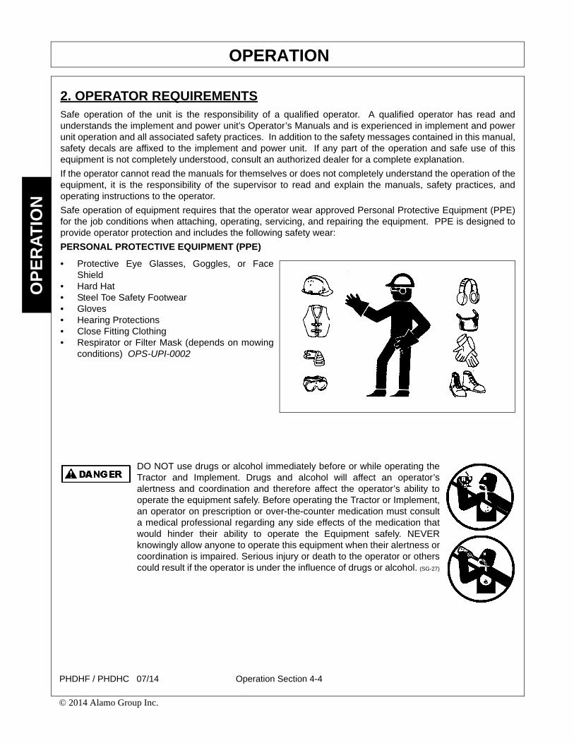
PERSONAL PROTECTIVE EQUIPMENT (PPE)
• Protective Eye Glasses, Goggles, or FaceShield
• Hard Hat• Steel Toe Safety Footwear• Gloves• Hearing Protections• Close Fitting Clothing• Respirator or Filter Mask (depends on mowing
conditions) OPS-UPI-0002
DO NOT use drugs or alcohol immediately before or while operating theTractor and Implement. Drugs and alcohol will affect an operator’salertness and coordination and therefore affect the operator’s ability tooperate the equipment safely. Before operating the Tractor or Implement,an operator on prescription or over-the-counter medication must consulta medical professional regarding any side effects of the medication thatwould hinder their ability to operate the Equipment safely. NEVERknowingly allow anyone to operate this equipment when their alertness orcoordination is impaired. Serious injury or death to the operator or otherscould result if the operator is under the influence of drugs or alcohol. (SG-27)
PHDHF / PHDHC 07/14 Operation Section 4-4
© 2014 Alamo Group Inc.

OPERATIONO
PE
RA
TIO
N
3. POWER UNIT REQUIREMENTS
The power unit used to operate the digger must have the power capacity to lift, pull, and operate the PowerTake Off (PTO) at the implement’s rated speed while traveling at a ground speed between 2 and 5 MPH.Operating the implement with a power unit that does not meet the following requirements may cause powerunit or implement damage and be a potential danger to the operator and passersby.
Power Unit Requirements and Capabilities• ASABE approved Roll-Over Protective Structure (ROPS) or ROPS cab and seat belt.• Tractor Safety Devices .....................Slow Moving Vehicle (SMV) emblem, lighting, PTO master shield• Auxiliary Hydraulics ..........................Planetary Digger Model must match the hydraulic output capacity of
the power unit operating the digger• Digger Model:
PHDHF15 ..................For Systems delivering 6-15 GPM at 3000 PSI Max.1419 ft./lbs. torque at 3000 PSI
PHDHF20 ..................For Systems delivering 10-20 GPM at 3000 PSI Max.1777 ft./lbs. torque at 3000 PSI
PHDHF30 ..................For Systems delivering 15-30 GPM at 3000 PSI Max.2632 ft./lbs. torque at 3000 PSI
PHDHC20..................For Systems delivering 10-20 GPM at 3000 PSI Max.2008 ft./lbs. torque at 3000 PSI
PHDHC30..................For Systems delivering 15-30 GPM at 3000 PSI Max.2937 ft./lbs. torque at 3000 PSI
PHDHC35..................For Systems delivering 20-35 GPM at 3000 PSI Max.3582 ft./lbs. torque at 3000 PSI
Do not operate the unit under any circumstance if the slope is 10 degrees or greater.
3.1 ROPS and Seat BeltThe power unit must be equipped with a Roll-Over-Protective-Structure (ROPS) and seat belt to protect theoperator from falling off the power unit, especially during a roll over where the driver could be crushed andkilled. Only operate the power unit with the ROPS in the raised position and seat belt fastened. Power unitsnot equipped with a ROPS and seat belt should have these life saving features installed by an authorizeddealer. OPS-UPI- 0003
Operate this Equipment only with a Power Unit equipped with anapproved operator Roll-Over Protective Structure (ROPS). Alwayswear seat belts. Serious injury or even death could result from fallingoff the Power Unit--particularly during a turnover when the operatorcould be pinned under the Operator Protective Structure. (SPU-14)
PHDHF / PHDHC 07/14 Operation Section 4-5
© 2014 Alamo Group Inc.

OPERATIONO
PE
RA
TIO
N
3.2 Power Unit Safety DevicesIf transporting or operating the power unit and implement near a public roadway, the power unit must beequipped with proper warning lighting and a Slow Moving Vehicle (SMV) emblem which are clearly visiblefrom the rear of the unit. Lights and an SMV emblem must be equipped directly on implements if the visibilityof the tractor warning signals are obscured.
Maintain all manufacturer equipped safety shields and guards. Always replace shields and guards that wereremoved for access to connect, service, or repair the power unit or implement. OPS-UPI- 0004
3.3 Auxiliary HydraulicsThe power unit must be equipped with auxiliary hydraulics and be rated for the hydraulic flow rating of thedigger model being used. Reference the power unit operator’s manual to determine the hydraulic outputspecifications of the power unit.Common hydraulic connection points for most power units are given below. Consult an authorized dealer ifthere are any questions on where to tap into the hydraulic system for your equipment.Skid Steer Loaders
-Boom auxiliary outletsBackhoes
-Auxiliary hydraulic outlets or bucket curl cylinder circuitLoader Buckets
-Auxiliary hydraulic outlets or bucket tilt (dump) cylinder circuit
NOTE: Some auxiliary outlets on these power units are one way circuits and turn on flow abruptly with suchforce that it can cause damage to hydraulic motors and other parts of the system and will not reverse themotor to free the auger in instances where it becomes lodged. Check this before installing on one of the powerunit outlets.
Determine the length of hose required to plumb the drive unit into the power unit hydraulic outlets. Be surehydraulic hoses are long enough to perform at the full range of the digger’s operating capacity. The diggerhydraulic hose quick couplers must be compatible with the couplers of the power unit. Hydraulic hoses andfittings must have a continuous operating pressure rating of at least 25% higher than the maximum pressureof the hydraulic system that the digger will be tapped into. OPS-PHD- 0001
4. GETTING ON AND OFF THE POWER UNITBefore getting onto the power unit, the operator must read and completely understand the implement andpower unit operator manuals. If any part of either manual is not completely understood, consult an authorizeddealer for a complete explanation. OPS-UPI-0005
Do not mount the Power Unit while the Power Unit is moving. Mount thePower Unit only when the Power Unit and all moving parts arecompletely stopped. (SPU-18)
PHDHF / PHDHC 07/14 Operation Section 4-6
© 2014 Alamo Group Inc.

OPERATIONO
PE
RA
TIO
N
4.1 Boarding the Power UnitUse both hands and equipped handrails and steps for support when boarding the power unit. Never usecontrol levers for support when mounting the power unit. Always seat yourself in the operator’s seat andsecure the seat belt around you. Only operate the power unit and implement with the ROPS in the raisedposition.
Never allow passengers to ride on the power unit or digger. Extra riders can easily fall off and beseriously injured or killed from falling off and being ran over. It is the operator’s responsibility to forbid all extrariders. OPS-UPI- 0006
Never allow children or other persons to ride on the Power Unit orImplement. Falling off can result in serious injury or death. (SPU-16)
Never allow children to operate, ride on, or come close to the Tractor orImplement. Usually, 16-17 year-old children who are mature andresponsible can operate the implement with adult supervision, if theyhave read and understand the Operator’s Manuals, been trained inproper operation of the tractor and Implement, and are physically largeenough to reach and operate the controls easily. (SPU-42)
4.2 Dismounting the Power UnitBefore dismounting, park the power unit and implement on a reasonably level surface, apply the parkingbrake, idle the engine down, disengage the PTO, and lower the implement to the ground. Shut down thepower unit engine according to the operator’s manual, remove the key, and wait for all motion to completelystop. Never leave the seat until the power unit, its engine and all moving parts have come to a complete stop.
Use hand rails and steps when exiting the power unit. Be careful of your step and use extra caution whenmud, ice, snow or other matter has accumulated on the steps or hand rails. Use all handrails and steps forsupport and never rush or jump off the power unit. OPS-UPI-0007
PHDHF / PHDHC 07/14 Operation Section 4-7
© 2014 Alamo Group Inc.

OPERATIONO
PE
RA
TIO
N
5. STARTING THE POWER UNITThe operator must have a complete understanding of the placement, function, and operational use of allpower unit controls before starting the power unit. Review the power unit operator’s manual and consult anauthorized dealer for power operation instructions if needed.
Essential Power Unit Controls:
• Locate the light control lever• Locate the engine shut off control• Locate the brake pedals and clutch • Locate the hydraulic remote control levers
Before starting the power unit ensure the following:
• Conduct all pre-start operation inspection and service according to the power unit operator’s manual. • Make sure all guards, shields, and other safety devices are securely in place.• The parking brake is on. • The hydraulic remote control levers are in the neutral position.• The power unit transmission levers are in park or neutral.
Refer to the power unit owner’s manual for power unit starting procedures. Only start the power unit whileseated and belted in the operator’s seat. Never bypass the ignition switch by short circuiting the startersolenoid. After the power unit engine is running, avoid accidental contact with the power unit transmission toprevent sudden and unexpected power unit movement. OPS-UPI-0009
Never run the Power Unit engine in a closed building or without adequate ventilation. Theexhaust fumes can be hazardous to your health. (SPU-23)
Start the Power Unit only when properly seated in the Power Unit seat. Startinga Power Unit in gear can result in injury or death. Read the Power UnitOperator’s Manual for proper starting instructions. (SPU-19)
6. PRE-OPERATION INSPECTION AND SERVICEBefore each use, a pre-operation inspection and service of the implement and power unit must be performed.This includes routine maintenance and scheduled lubrication, inspecting that all safety devices are equippedand functional, and performing needed repairs. Do not operate the implement and power unit it the pre-operation inspection reveals any condition affecting safe operation. Perform repairs and replacement ofdamaged and missing parts as soon as noticed. By performing a thorough pre-operation inspection andservice, valuable down time and repair cost can be avoided. OPS-UPI-0008
PHDHF / PHDHC 07/14 Operation Section 4-8
© 2014 Alamo Group Inc.

OPERATIONO
PE
RA
TIO
N
Always disconnect the auxiliary hydraulic couplers from the Power Unit before performingservice on the Implement. Never work on the Implement with the Power Unit auxiliary hydraulics connected. Rotating parts such as blades could turn without warning and causeimmediate entanglement, injury or death. (SPU-31)
Periodically inspect all moving parts for wear and replace whennecessary with authorized service parts. Look for loose fasteners, wornor broken parts, and leaky or loose fittings. Make sure all pins havecotter pins and washers. Serious injury may occur from not maintainingthis machine in good working order. (SG-21)
6.1 Power Unit Pre-Operation Inspection/ServiceRefer to the power unit operator’s manual to ensurea complete pre-operation inspection and scheduledservice is performed according to themanufacturers recommendations. The followingare some of the items that require daily service andinspection:
• Tire condition/air pressure• Wheel lug bolts • Steering linkage• SMV sign is clean and visible• Seat belt is in good condition • ROPS is in good condition• ROPS is in the raised position• No oil leaks • Radiator free of debris • Engine oil level and condition• Engine coolant level and condition • Power brake fluid level • Power steering fluid level • Fuel condition and level • Sufficient lubrication at all lube points• Air filter condition OPS-UPI-0010
PHDHF / PHDHC 07/14 Operation Section 4-9
© 2014 Alamo Group Inc.

OPERATIONO
PE
RA
TIO
N
6.2 Digger Pre-Operation Inspection/ServiceBefore each digger use, a complete inspection and service is required to ensure the digger is in a good andsafe working condition. Damaged and/or broken parts should be repaired and/or replaced immediately. Toensure the digger is ready for operation, conduct the following:
The operator’s manual and safety signs affixed onthe unit contain important instructions on the safeand proper use of the equipment. Maintain theseimportant safety features on the implement in goodcondition to ensure the information is available tothe operator at all times.
• Ensure the manual canister has been located inarea convenient for operator access.
• Ensure all safety signs are in place and legible.Replace missing, damaged, and illegibledecals. OPS-PHD- 0003
The operator’s manual and decals affixed on the unitcontain important instructions on the safe and properuse of the equipment. Maintain these important safetyfeatures on the implement in good condition to ensurethe information is available to the operator at all times.
• Ensure the digger hitch is securely attached to thepower unit.
• Check for hydraulic oil leaks on the drive motor,along the hydraulic lines, and at the hydraulicports.
IMPORTANT: DO NOT use your hands to check for oilleaks. Use a piece of heavy paper or cardboard tocheck for hydraulic leaks.
• Inspect planetary reduction gear oil level andreplenish if needed. A low oil level is a warningsign that the gearbox may be cracked or its seal isdamaged and needs to be replaced. OPS-PHD-0002_A
PHDHF / PHDHC 07/14 Operation Section 4-10
© 2014 Alamo Group Inc.

OPERATIONO
PE
RA
TIO
N
HYDRAULIC POST HOLE DIGGER Pre-Operation Inspection
Digger ID#_______________________ Make____________________
Date_____________________________Shift____________________
Before conducting the inspection, make sure the Tractor engine is off, allrotation has stopped and the tractor is in park, with the parking brakeengaged. Make sure the Post Hole Digger is resting on the ground or securelyblocked up and all hydraulic pressure has been relieved.
Operator’s Signature:_____________________________________________________________
Item Condition at Start of Shift
Specific Comments if not O.K.
The Operator’s Manual is in the Canister on the Digger
All Safety Decals are in place and legible
The attachment mounting bolts and pins are tight
There are no cracks in mounting members
There are no cracks in the Post Hole Digger frame
The hydraulic cylinder pins are properly retained
There are no leaking or damaged hoses
Auger connection guards are in place, in good condition
Gearbox mounting pins/bolts are in place and retained
Gearbox oil is at the proper level
The auger connection bolts are in place and guarded
The auger blades are not chipped, cracked or bent
The auger blade bolts are tight
The auger is clear of caked mud and debris
DO NOT OPERATE an UNSAFE TRACTOR or FRONT END LOADER
PHDHF / PHDHC 07/14 Operation Section 4-11
© 2014 Alamo Group Inc.
OPERATIONO
PE
RA
TIO
N
7. OPERATING THE POWER UNIT AND IMPLEMENTTHE OPERATOR MUST COMPLETELY UNDERSTAND HOW TO OPERATE THE POWER UNIT ANDIMPLEMENT AND ALL CONTROLS BEFORE STARTING TO DIG. The operator must read and understandthe Safety and Operation Sections of the implement and power unit operator’s manuals. These manuals mustbe read and explained to any operator who cannot read. Never allow someone to operate the implement andpower unit without complete operating instructions.
Before starting any digging operation, the operator must become familiar with the area and any obstacles andhazards contained within to ensure safety to the operator, bystanders, and equipment. OPS-UPI- 0011
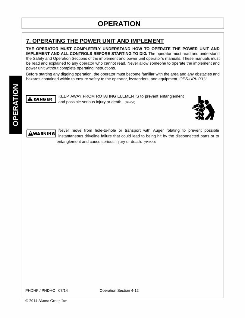
KEEP AWAY FROM ROTATING ELEMENTS to prevent entanglement
and possible serious injury or death. (SPHD-2)
Never move from hole-to-hole or transport with Auger rotating to prevent possible
instantaneous driveline failure that could lead to being hit by the disconnected parts or to
entanglement and cause serious injury or death. (SPHD-10)
PHDHF / PHDHC 07/14 Operation Section 4-12
© 2014 Alamo Group Inc.

OPERATIONO
PE
RA
TIO
N
7.1 Digger Operating Instructions
1. Spot auger pilot over mark where hole is to be drilled. LOCK POWER UNIT BRAKES - if power unit rollsforward or backwards with auger in the ground, the auger, gearbox, or hitch may be damaged or broken.
2. With auger raised off the ground less than 12”, and the power unit engine set at a lower RPM, activate thedigger hydraulic control valve to determine position control lever must be in to turn auger in forward(clockwise) rotation. This is the “digging” position.
3. Before beginning to dig, experiment with auger speed to determine a suitable auger RPM. Generally inlight and sandy soils a high RPM is needed. To increase auger RPM, increase the power unit engine RPM.To decrease auger rotation speed, decrease power unit engine RPM.
4. Return digger hydraulic control lever to neutral position to stop the auger rotation. Lower the auger to theground so that only the center point penetrates the ground above 2”.
5. Activate the hydraulic control lever to digging position to start auger turning in a forward (clockwise)rotation. Use only enough down pressure to assure positive penetration of auger into the ground. Ease upon down pressure if auger rotation slows down drastically or stalls.
6. After the auger has penetrated the ground about 24”, raise the auger from hole to clean dirt out. Repeatthis procedure until the desired hole depth is achieved. Allow auger to turn a few seconds at this depth toclean the hole.
7. Return digger hydraulic control valve to the neutral position to disengage the auger and stop rotation. Withauger at a complete stop, raise auger out of the hole, move auger away from the hole, and re-engage tospin loose soil off the auger flighting.
NOTE: Do not reverse the auger direction to remove the auger from the hole as loose soil or the auger willfall back in the hole.
8. If necessary, repeat steps 6 and 7 to obtain a cleaner hole.9. In some digging conditions or when excessive down pressure is applied, the auger may “screw” itself into
the ground and become stuck causing the digger to stall. When this happens, reverse the auger rotation(move hydraulic control lever in opposite direction so that auger turns counter-clockwise) and slowly raisethe auger out of the hole. Once unstuck, return the control valve lever to the forward rotation position toresume digging.
If the auger becomes lodged under rocks, roots or other large obstruction, do not attempt to raise the augerout of the hole. The auger must be rotated in the reverse direction to unscrew the flighting from theobstruction.
10. If the auger hits and becomes lodged with a large obstruction, the power unit hydraulic relief valve will openand bypass the oil to stall (stop) the auger. This does not damage the digger or power unit in any way butserves as an overload protection device. When this happens, simply reverse the auger rotation and slowlyraise the auger. The relief valve will reset automatically, and the drilling operation can be resumed.
11. Avoid excessive shield loading to the auger and drive motor which can cause drive unit, auger and hitchdamage.
12. Keep auger teeth and points in good condition. Check condition frequently and always keep spare teethreadily available so that worn and missing teeth can be replaced as detected to avoid damage to toothholders and auger flighting.
PHDHF / PHDHC 07/14 Operation Section 4-13
© 2014 Alamo Group Inc.

OPERATIONO
PE
RA
TIO
N
7.2 Auger Selection Based on Drilling Application
The digger must be equipped with the proper auger type for the drilling application at hand. A wide range ofaugers and sizes are available for drilling in compacted soils, frozen ground, and loose and solid rock. In someapplications the digger can be used to drill concentrate (without rebar) if adequate down pressure can beapplied to the auger by the power unit (not recommended for skid steer operated units).
PUFF Auger: Designed to drill 2” diameter holes in solid rock or concrete for T-posts. Also referred to as the T-post Puff Auger.
SDA Augers: Designed for digging in soil only. Available in sizes from 6” to 36” diameter, and tree augers from18” to 36” diameter sizes.
RAD Augers: Designed for digging in soil, clay, loose and solid rock and concrete. Available in sizes from 9” to36” diameter.
SRA Augers: Designed for drilling in solid rock or concrete without rebar, fractured rock, frozen ground andcompacted soil. Augers are available in sizes from 4.5” to 6” diameter.
Maximum Diameter Auger Sizes for Digger Model
DIGGER DIRT ROCKPHDHC20 30” 24”PHDHC30 36” 36”PHDHC35 36” 36”
PHDHF15 18” N/APHDHF20 30” 9”PHDHF30 36” 12”
* Available for C-Series Planetary Drive Diggers** Available for H-Series Planetary Drive Diggers
PHDHF / PHDHC 07/14 Operation Section 4-14
© 2014 Alamo Group Inc.

OPERATIONO
PE
RA
TIO
N
8. IMPLEMENT STORAGEProperly preparing and storing the implement at the end of the season is critical to maintaining its appearanceand to help ensure years of dependable service. The following are suggested storage procedures:
• Thoroughly clean all dirt and other debris from the implement.• Check the planetary reduction gear oil level and fill as necessary.• Tighten all bolts and pins to the recommended torque.• Check the implement and auger for worn and damaged parts. Perform repairs and make replacements
immediately so that the implement will be ready for use at the start of the next season.• Keep the hydraulic hoses from sitting in water, dirt and other contaminants.• Use spray touch-up enamel where necessary to prevent rust and to maintain appearance of the
implement. OPS-UPI- 0012
Never allow children to play on or around Power Unit or Implement. Children can slip or fall
off the Equipment and be injured or killed. Children can cause the Implement to shift or fall
crushing themselves or others. (SPU-24)
9. TRANSPORTING THE POWER UNIT AND IMPLEMENTInherent dangers of operating the power unit and implement and the possibility of accidents are not left behindwhen you finish working in an area. Therefore, the operator must employ good judgement and safe operationpractices when transporting the power unit and implement between locations. By using good judgement andfollowing safe transport procedures, the possibility of accidents while moving between locations can besubstantially minimized. OPS-UPI- 0013
Never allow children or other persons to ride on the Power Unit orImplement. Falling off can result in serious injury or death. (SPU-16)
PHDHF / PHDHC 07/14 Operation Section 4-15
© 2014 Alamo Group Inc.

OPERATIONO
PE
RA
TIO
N
Before transporting the power unit on a publicroadway or boarding a trailer for transport, thepower brake pedals should be locked together.Locking the pedals ensures that both wheels brakesimultaneously while stopping, especially whenmaking an emergency stop.
Use extreme caution and avoid hard applications ofthe power unit brakes when towing heavy loads atroad speeds. Never tow the implement at speedsgreater than 20 MPH. OPS-UPI- 0014
9.1 Transporting on Public RoadwaysExtreme caution should be used when transporting the power unit and implement on public roadways. Thepower unit must be equipped with all required safety warning features including a SMV emblem and flashingwarning lights to alert drivers of the power unit’s presence. Remember that roadways are primarily designedfor automotive drivers and most drivers will not be looking out for you, therefore, you must look out for them.Check your side view mirrors frequently and remember that vehicles will approach quickly because of thepower unit’s slower speed. Be extremely cautious when the piece of equipment that you are towing is widerthan the power unit tire width and/or extends beyond your lane of the road.
OPS-UPI- 0015
Make certain that the “Slow Moving Vehicle” (SMV) sign is installed insuch a way as to be clearly visible and legible. When transporting theEquipment use the Tractor flashing warning lights and follow all localtraffic regulations. (SG-6)
The SMV (Slow-Moving Vehicle) emblem isuniversal symbol used to alert drivers of thepresence of equipment traveling on roadways at aslow speed. SMV signs are a triangular brightorange with reflective red trim for both easy dayand night visibility. Make sure the SMV sign isclean and visible from the rear of the unit beforetransporting the tractor and implement on a publicroadway. Replace the SMV emblem if faded,damaged, or no longer reflective. OPS-U- 0020
PHDHF / PHDHC 07/14 Operation Section 4-16
© 2014 Alamo Group Inc.

OPERATIONO
PE
RA
TIO
N
Make sure that all power unit flashing warning lights,headlights, and brake/tail lights are functioningproperly before proceeding onto public roads. Whilenewer model power units have plenty of lighting toprovide warning signals and operating lighting, mostolder models are only equipped with operating lights.Consult an authorized dealer for lighting kits andmodifications available to upgrade the lighting onolder power unit models. OPS-UPI- 0016
When operating on public roads, have considerationfor other road users. Pull to the side of the roadoccasionally to allow all following traffic to pass. Donot exceed the legal speed limit set in your countryfor agricultural power units. Always stay alert whentransporting the power unit and implement on publicroads. Use caution and reduce speed if othervehicles or pedestrians are in the area. OPS-UPI-0017
Reduce speed before turning or applying the brakes.Ensure that both brake pedals are locked togetherwhen operating on public roads. OPS-U- 0023
PHDHF / PHDHC 07/14 Operation Section 4-17
© 2014 Alamo Group Inc.

OPERATIONO
PE
RA
TIO
N
9.2 Hauling the Power Unit andImplementBefore transporting a loaded power unit andimplement, measure the height and widthdimensions and gross weight of the completeloaded unit. Ensure that the load will be incompliance with the legal limits set for the areas thatwill be traveled through. OPS-UPI- 0018
Use adequately sized and rated trailers andequipment to transport the power unit and implement.Consult an authorized dealer to determine the properequipment required. Using adequately sized chains,heavy duty straps, cables and/or binders, securely tiedown both the front and rear of the power unit utilizingthe proper tie down locations as specified by thepower unit manufacturer. OPS-U- 0025
Arrange the chains so that when tightened, thechains are pulling downward and againstthemselves. Carefully tighten the securing chains orother fasteners using boomers or binders to applymaximum tension. Use extreme care whenattaching and removing the securing devices as theextreme tension involved when released has thepotential to inflict serious injury.
While hauling the power unit and implement, makeoccasional stops to check that the power unit andimplement have not moved or shifted and that thesecuring chains have maintained tension. If duringtransport a hard braking, sharp turning, or swervingaction was performed, stop at the next safe locationto inspect the security of the load. OPS-UPI- 0020
PHDHF / PHDHC 07/14 Operation Section 4-18
© 2014 Alamo Group Inc.

OPERATIONO
PE
RA
TIO
N
10. TROUBLESHOOTING GUIDE
TROUBLE POSSIBLE CAUSE POSSIBLE REMEDY
Gearbox Leaking Damage oil seal. Replace seal.No oil seal. Install oil seal.Oil too light. Use EP 140.Oil seal race rough. Replace shaft or replace race.Oil Seal installed wrong. Replace seal.Oil seal not sealing in Replace seal or use a sealantthe housing. on O.D. of seal.Bearing loose. Adjust bearings.Oil level too high. Drain oil to proper level.Gasket damaged. Replace gasket.Bolts loose. Tighten bolts.
Trouble Digging Hole Dull or broken auger teeth. Replace damaged and missingteeth.
Auger speed too fast. For drilling rock, slow speed downas much as possible.
Auger not digging vertical. Level digger frame.
Slow Speed or Insufficient Low oil pressure or Check pressure relief valve settingDigging Power restricted oil flow and hydraulic pump output by
installing a combination flow andpressure gauge in hydraulic linesupplying the drive motor. Gaugemust be installed beyond all valvesand quick disconnects to get a truereading at the drive unit. Thehydraulic system flow (GPM) shouldremain constant and not drop offuntil the stall pressure (PSI) isreached. If pressure readings arenot up to the power unitmanufacturer’s specifications, checkfor faulty relief valve and adjust orreplace as required. A worn,damaged, or insufficient pump willalso cause low oil pressure andrestricted oil flow.
PHDHF / PHDHC 07/14 Operation Section 4-19
© 2014 Alamo Group Inc.

OPERATIONO
PE
RA
TIO
N
TROUBLE POSSIBLE CAUSE POSSIBLE REMEDY
Excessive Hydraulic Restricted Hydraulic lines Clean or replace hydraulic lines.Oil Heating
Oil passing over relief valve Decrease down pressure appliedtoo frequently. to auger.Insufficient hydraulic oil Contact power unit manufacturerreservoir size to pump for increasing reservoir size or output ratio. adding oil cooler.Dirty or contaminated Replace power unit hydraulic oilhydraulic oil. and hydraulic oil filters.
PHDHF / PHDHC 07/14 Operation Section 4-20
© 2014 Alamo Group Inc.

Maintenance Section 5-1
MAINTENANCE SECTION
MAINTENANCEM
AIN
TE
NA
NC
E
Before operating the Post Hole Digger, make sure it is properly lubricated and thoroughly inspected. Only aminimum of time and effort is required to regularly lubricate and maintain this machine to provide long life andtrouble free operation.
LUBRICATION INFORMATIONThe drilling machine must be properly lubricated to achieve the best operation and longest life. Clean excessgrease and hydraulic oil from the drilling machine, especially when operating in sandy conditions.
Each day before use...Check gearbox for signs of leaking around seals. Occasionally, seals will leak if the unitsits for a prolonged period of time. However, seals should quit leaking following a short period of operation. Ifseals do not quit leaking, replace seals at once and refill gearbox oil.
ONLY USE CLEAN HYDRAULIC OIL
80% of all hydraulic component failures are caused by contamination of the hydraulic oil. Always keep all dirtand other contaminants from entering the hydraulic system. Always use dust caps and plugs on all quickdisconnects when not in use. Tightly cap all hydraulic openings to hold oil in and to prevent dirt and othercontaminants from entering the hydraulic system. Check condition of the hydraulic oil daily for contamination. Ifcontamination is present, determine its source and make necessary repairs immediately.
Reduced viscosity of hydraulic fluids occurs at higher operating temperatures and causes a breakdown of fluidadditives such as wear inhibitors. Excessive heat will cause higher internal leakage in the drive unit motor,resulting in less efficient motor performance. Excessive heat can also result in drive motor seals becomingbrittle and cracked.
INSPECT HYDRAULIC HOSES AND HOSE ASSEMBLIES DAILY
Excessive heat, age and exposure to the weather can cause hose covers to become brittle and to crack.Replace hoses before failure to prevent loss of hydraulic oil, time consuming “bleeding” of the system, andhydraulic oil cavitation. Operating faulty hoses increases the chances of personal injury caused by escapinghydraulic fluid during a hydraulic hose failure.
CHECK DRIVE MOTOR DAILY
The planetary reduction gear has been filled with lubricant by the manufacturer. If oil is observed leaking, theseal should be inspected for damage or wear and replaced if necessary. Inspect gearbox for any otherdamage, which could be causing oil leakage, make required repairs, and refill with lubricant. Whenreassembled, fill the PHDHF-Series with 13.5 ounces and the PHDHC-Series with 27 ounces of fresh API-GL-5 No. 80 or 90 oil.
PHDHF / PHDHC 07/14 Maintenance Section 5-2
© 2014 Alamo Group Inc.

MAINTENANCEM
AIN
TE
NA
NC
E
AUGER MAINTENANCEInspect auger to loose, worn, broken and missing cutting teeth and points. Worn teeth and points can greatlyaffect auger penetration and greatly reduce auger life expectancy. Always keep spare teeth and points onhand. Some digging may require inspecting teeth and point condition more frequently.
On rock augers, inspect the wear of hardfacing. If worn away, re-hardface surface immediately. Failure tomaintain hardfacing will allow excessive wear on pockets and will ruin auger.
MACHINE INSPECTION
CHECK DRIVE UNIT AND ALL ACCESSORIES DAILY
Inspect the drive unit and all accessories daily for loose, bent, cracked, or worn bolts or fasteners. Always usegrade 5 or harder replacement bolts. Always use lock washers with standard hex nuts or lock nuts.
Repair or replace any worn parts immediately. Remember that drilling applicant can be hard wor, for anymachine. Under extreme conditions parts can wear or break. Using any machine without proper maintenanceof all parts can cause further damage to good parts.
Check to ensure that all pins and bolts are secured in place and are tightened to the proper torque.
STORAGEYour rotary mower represents an investment from which you should get the greatest possible benefit.Therefore, when the season is over, the implement should be thoroughly checked and prepared for storage sothat a minimum amount of work will be required to put it back into operation for the next season. The followingare suggested storage procedures:
1. Thoroughly clean the implement.2. Lubricate the implement as covered in Maintenance Section.3. Tighten all bolts and pins to the recommended torque.4. Check the implement for worn or damaged parts. Make replacements immediately.5. Store the implement in a clean, dry place with the implement housing resting on blocks.6. Use spray touch-up enamel where necessary to prevent rust and maintain the appearance of the
implement.
PHDHF / PHDHC 07/14 Maintenance Section 5-3
© 2014 Alamo Group Inc.

MAINTENANCEM
AIN
TE
NA
NC
E
HYDRAULIC LINES, COUPLERS & ADAPTERSKeep all hoses and adapters tight. Repair any leaks immediately. Do not overtighten hose end fittings. Tightento specifications only. (See Chart below)
PROPER TORQUE FOR FASTENERSThe chart lists the correct tightening torque for fasteners. When bolts are to be tightened or replaced, refer tothis chart to determine the grade of bolts and the proper torque except when specific torque values areassigned in manual text.
RECOMMENDED TORQUE IN FOOT POUNDS UNLESS OTHERWISE STATED IN THE MANUAL*
NOTE: These values apply to fasteners as received from supplier, dry or when lubricated with normal engineoil. They do not apply if special graphited or molydisulphide greases or other extreme pressure lubricants areused. This applies to both UNF fine and UNC coarse threads.
PHDHF / PHDHC 07/14 Maintenance Section 5-4
© 2014 Alamo Group Inc.
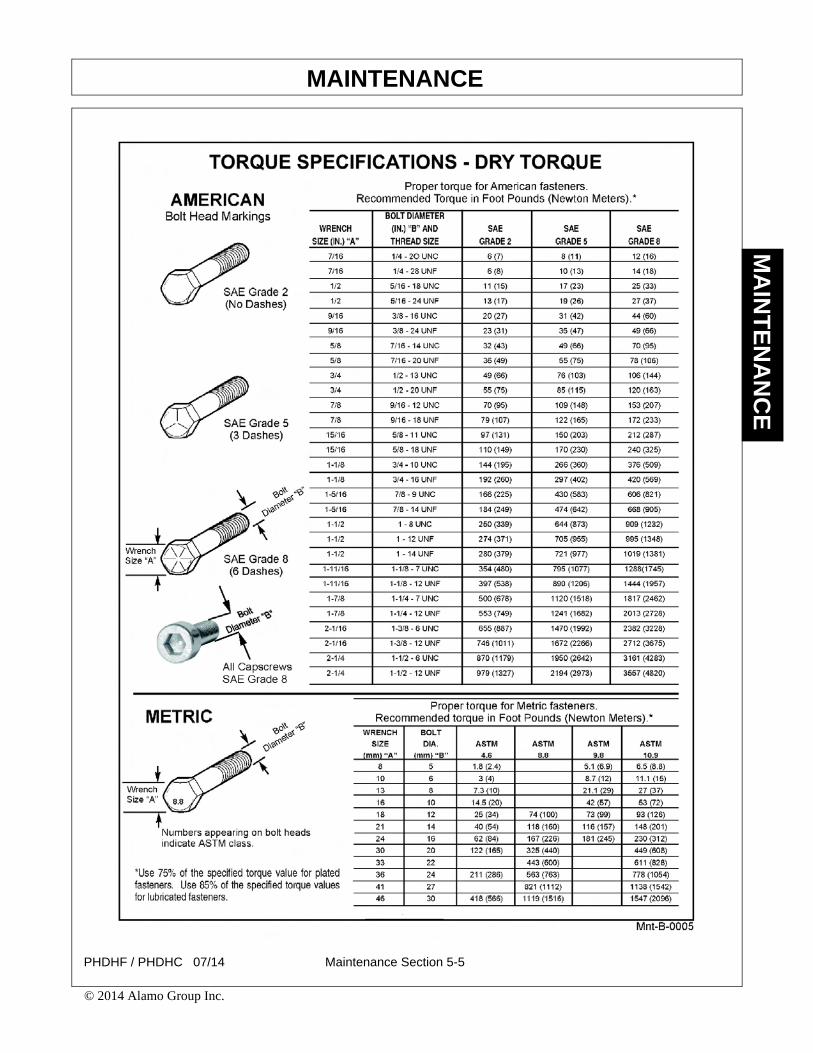
MAINTENANCEM
AIN
TE
NA
NC
E
PHDHF / PHDHC 07/14 Maintenance Section 5-5
© 2014 Alamo Group Inc.


TO THE OWNER/OPERATOR/DEALER
To keep your implement running efficiently and safely, read your manual thoroughly and follow these directionsand the Safety Messages in this Manual. The Table of Contents clearly identifies each section where you caneasily find the information you need.The OCCUPATIONAL SAFETY AND HEALTH ACT (1928.51 Subpart C) makes these minimum safetyrequirements of tractor operators:
REQUIRED OF THE OWNER:1. Provide a Roll-Over-Protective Structure that meets the requirements of this Standard; and2. Provide Seat belts that meet the requirements of this paragraph of this Standard and SAE J4C; and3. Ensure that each employee uses such Seat belt while the tractor is moving; and4. Ensure that each employee tightens the Seat belt sufficiently to confine the employee to the protected area provided by the ROPS
REQUIRED OF THE OPERATOR:1. Securely fasten seat belt if the tractor has a ROPS.2. Where possible, avoid operating the tractor near ditches, embankments, and holes.3. Reduce speed when turning, crossing slopes, and on rough, slick, or muddy surfaces.4. Stay off slopes too steep for safe operation.5. Watch where you are going - especially at row ends, on roads, and around trees.6. Do not permit others to ride.7. Operate the tractor smoothly - no jerky turns, starts, or stops.8. Hitch only to the drawbar and hitch points recommended by the tractor manufacturer.9. When the tractor is stopped, set brakes securely and use park lock, if available.
x Keep children away from danger all day, every day...
x Equip tractors with rollover protection (ROPS) and keep all machinery guards in place...
x Please work, drive, play and live each day with care and concern for your safety and that of your family and fellow citizens.

PHDHF15, PHDHF20, PHDHF30, PHDHC20, PHDHC30, PHDHC35-SOM-07/14 P/N 50074550Printed U.S.A
PHDHF15, PHDHF20, PHDHF30PHDHC20, PHDHC30, PHDHC35
HYDRAULIC PLANETARYDRIVE DIGGER


![PART HEARD MATTERS [PERSONAL APPEARANCE CASES] · sunny choudhary[impl], santosh a kumar - i[impl], plr chambers and co.[impl], m. p. vinod[impl], g. prakash[impl][gr] {mention memo}](https://static.fdocuments.net/doc/165x107/5eca55a2c38f4e40c93e9850/part-heard-matters-personal-appearance-cases-sunny-choudharyimpl-santosh-a.jpg)