
Operator’s Manual AutoDrive 4R100 - Lincoln Electric · · 2016-06-15SECTION A: WARNINGS C...
32
Operator’s Manual AutoDrive ® 4R100 Register your machine: www.lincolnelectric.com/register Authorized Service and Distributor Locator: www.lincolnelectric.com/locator IM10069-B | Issue Date Apr-13 © Lincoln Global, Inc. All Rights Reserved. For use with machines having Code Numbers: 11729, 11884, 11955 Save for future reference Date Purchased Code: (ex: 10859) Serial: (ex: U1060512345)
Transcript of Operator’s Manual AutoDrive 4R100 - Lincoln Electric · · 2016-06-15SECTION A: WARNINGS C...

Operator’s Manual
AutoDrive ® 4R100
Register your machine: www.lincolnelectric.com/register
Authorized Service and Distributor Locator: www.lincolnelectric.com/locator
IM10069-B | Issue D ate Apr-13
© Lincoln Global, Inc. All Rights Reserved.
For use with machines having Code Numbers:
11729, 11884, 11955
Save for future reference
Date Purchased
Code: (ex: 10859)
Serial: (ex: U1060512345)
THANK YOU FOR SELECTING A QUALITY PRODUCT BY LINCOLN ELEC TRIC.
PLEASE EXAMINE CARTON AND EQUIPMENT FORDAMAGE IMMEDIATELY
When this equipment is shipped, title passes to the purchaserupon receipt by the carrier. Consequently, claims for materialdamaged in shipment must be made by the purchaser against thetransportation company at the time the shipment is received.
SAFETY DEPENDS ON YOU
Lincoln arc welding and cutting equipment is designed and builtwith safety in mind. However, your overall safety can be increasedby proper installation ... and thoughtful operation on your part. DO NOT INSTALL, OPERATE OR REPAIR THIS EQUIPMENT WITHOUT READING THIS MANUAL AND THE SAFETYPRECAUTIONS CONTAINED THROUGHOUT. And, most importantly,think before you act and be careful.
This statement appears where the information must be followedexactly to avoid serious personal injury or loss of life.
This statement appears where the information must be followedto avoid minor personal injury or damage to this equipment.
KEEP YOUR HEAD OUT OF THE FUMES.
DON’T get too close to the arc.Use corrective lenses if necessaryto stay a reasonable distanceaway from the arc.
READ and obey the Safety DataSheet (SDS) and the warning labelthat appears on all containers ofwelding materials.
USE ENOUGH VENTILATION orexhaust at the arc, or both, tokeep the fumes and gases from your breathing zone and the general area.
IN A LARGE ROOM OR OUTDOORS, natural ventilation may beadequate if you keep your head out of the fumes (See below).
USE NATURAL DRAFTS or fans to keep the fumes away from your face.
If you de velop unusual symptoms, see your supervisor. Perhaps the welding atmosphere and ventilation system should be checked.
WEAR CORRECT EYE, EAR & BODY PROTECTION
PROTECT your eyes and face with welding helmetproperly fitted and with proper grade of filter plate(See ANSI Z49.1).
PROTECT your body from welding spatter and arcflash with protective clothing including woolenclothing, flame-proof apron and gloves, leatherleggings, and high boots.
PROTECT others from splatter, flash, and glarewith protective screens or barriers.
IN SOME AREAS, protection from noise may be appropriate.
BE SURE protective equipment is in good condition.
Also, wear safety glasses in work areaAT ALL TIMES.
SPECIAL SITUATIONSDO NOT WELD OR CUT containers or materials which previouslyhad been in contact with hazardous substances unless they areproperly cleaned. This is extremely dangerous.
DO NOT WELD OR CUT painted or plated parts unless specialprecautions with ventilation have been taken. They can releasehighly toxic fumes or gases.
Additional precautionary measuresPROTECT compressed gas cylinders from excessive heat,mechanical shocks, and arcs; fasten cylinders so they cannot fall.
BE SURE cylinders are never grounded or part of an electrical circuit.
REMOVE all potential fire hazards from welding area.
ALWAYS HAVE FIRE FIGHTING EQUIPMENT READY FORIMMEDIATE USE AND KNOW HOW TO USE IT.
WARNING
CAUTION
Safety 01 of 04 - 06/15/2016

SECTION A:WARNINGS
CALIFORNIA PROPOSITION 65 WARNINGS
Diesel EnginesDiesel engine exhaust and some of its constituents are known to the State of California to cause cancer, birth defects, and otherreproductive harm.
Gasoline EnginesThe engine exhaust from this product contains chemicals known to the State of California to cause cancer, birth defects, or otherreproductive harm.
ARC WELDING CAN BE HAZARDOUS. PROTECTYOURSELF AND OTHERS FROM POSSIBLE SERIOUSINJURY OR DEATH. KEEP CHILDREN AWAY. PACEMAKER WEARERS SHOULD CONSULT WITHTHEIR DOCTOR BEFORE OPERATING.
Read and understand the following safety highlights. Foradditional safety information, it is strongly recommended that you purchase a copy of “Safety in Welding & Cutting - ANSI Standard Z49.1” from the American Welding Society, P.O. Box 351040, Miami, Florida 33135 or CSA Standard W117.2-1974. A Free copy of “Arc Welding Safety” booklet E205 is available from the Lincoln Electric Company, 22801 St. Clair Avenue, Cleveland, Ohio 44117-1199.
BE SURE THAT ALL INSTALLATION, OPERATION,MAINTENANCE AND REPAIR PROCEDURES AREPERFORMED ONLY BY QUALIFIED INDIVIDUALS.
FOR ENGINE POWEREDEQUIPMENT.
1.a. Turn the engine off before troubleshootingand maintenance work unless themaintenance work requires it to be running.
1.b. Operate engines in open, well-ventilatedareas or vent the engine exhaust fumes outdoors.
1.c. Do not add the fuel near an open flamewelding arc or when the engine is running.Stop the engine and allow it to cool beforerefueling to prevent spilled fuel fromvaporizing on contact with hot engine partsand igniting. Do not spill fuel when fillingtank. If fuel is spilled, wipe it up and do not start engine untilfumes have been eliminated.
1.d. Keep all equipment safety guards, covers and devices in position and in good repair.Keep hands, hair, clothing and tools away from V-belts, gears, fans and all other moving parts when starting, operating orrepairing equipment.
1.e. In some cases it may be necessary to remove safety guards toperform required maintenance. Remove guards only whennecessary and replace them when the maintenance requiringtheir removal is complete. Always use the greatest care whenworking near moving parts.
1.f. Do not put your hands near the engine fan. Do not attempt tooverride the governor or idler by pushing on the throttle controlrods while the engine is running.
1.g. To prevent accidentally starting gasoline engines while turningthe engine or welding generator during maintenance work,disconnect the spark plug wires, distributor cap or magneto wireas appropriate.
1.h. To avoid scalding, do not remove the radiatorpressure cap when the engine is hot.
ELECTRIC ANDMAGNETIC FIELDS MAYBE DANGEROUS
2.a. Electric current flowing through any conductorcauses localized Electric and Magnetic Fields (EMF). Welding current creates EMF fields around welding cables and welding machines
2.b. EMF fields may interfere with some pacemakers, and welders having a pacemaker should consult their physicianbefore welding.
2.c. Exposure to EMF fields in welding may have other health effectswhich are now not known.
2.d. All welders should use the following procedures in order tominimize exposure to EMF fields from the welding circuit:
2.d.1. Route the electrode and work cables together - Securethem with tape when possible.
2.d.2. Never coil the electrode lead around your body.
2.d.3. Do not place your body between the electrode and workcables. If the electrode cable is on your right side, thework cable should also be on your right side.
2.d.4. Connect the work cable to the workpiece as close as pos-sible to the area being welded.
2.d.5. Do not work next to welding power source.
SAFETY
Safety 02 of 04 - 06/15/2016

ELECTRIC SHOCK CAN KILL.
3.a. The electrode and work (or ground) circuits areelectrically “hot” when the welder is on. Donot touch these “hot” parts with your bare skin or wet clothing.Wear dry, hole-free gloves to insulate hands.
3.b. Insulate yourself from work and ground using dry insulation.Make certain the insulation is large enough to cover your full areaof physical contact with work and ground.
In addition to the normal safety precautions, ifwelding must be performed under electricallyhazardous conditions (in damp locations or whilewearing wet clothing; on metal structures such asfloors, gratings or scaffolds; when in crampedpositions such as sitting, kneeling or lying, if thereis a high risk of unavoidable or accidental contactwith the workpiece or ground) use the followingequipment:
• Semiautomatic DC Constant Voltage (Wire) Welder.
• DC Manual (Stick) Welder.
• AC Welder with Reduced Voltage Control.
3.c. In semiautomatic or automatic wire welding, the electrode,electrode reel, welding head, nozzle or semiautomatic weldinggun are also electrically “hot”.
3.d. Always be sure the work cable makes a good electricalconnection with the metal being welded. The connection shouldbe as close as possible to the area being welded.
3.e. Ground the work or metal to be welded to a good electrical (earth)ground.
3.f. Maintain the electrode holder, work clamp, welding cable andwelding machine in good, safe operating condition. Replacedamaged insulation.
3.g. Never dip the electrode in water for cooling.
3.h. Never simultaneously touch electrically “hot” parts of electrodeholders connected to two welders because voltage between thetwo can be the total of the open circuit voltage of bothwelders.
3.i. When working above floor level, use a safety belt to protectyourself from a fall should you get a shock.
3.j. Also see It ems 6.c. and 8.
ARC RAYS CAN BURN.
4.a. Use a shield with the proper filter and cover plates to protect youreyes from sparks and the rays of the arc when welding orobserving open arc welding. Headshield and filter lens shouldconform to ANSI Z87. I standards.
4.b. Use suitable clothing made from durable flame-resistant materialto protect your skin and that of your helpers from the arc rays.
4.c. Protect other nearby personnel with suitable, non-flammablescreening and/or warn them not to watch the arc nor exposethemselves to the arc rays or to hot spatter or metal.
FUMES AND GASESCAN BE DANGEROUS.
5.a. Welding may produce fumes and gaseshazardous to health. Avoid breathing these fumes and gases.When welding, keep your head out of the fume. Use enoughventilation and/or exhaust at the arc to keep fumes and gasesaway from the breathing zone. When welding hardfacing(see instructions on container or SDS) or on leador cadmium plated steel and other metals orcoatings which produce highly toxic fumes, keepexposure as low as possible and within applicableOSHA PEL and ACGIH TLV limits using localexhaust or mechanical ventilation unless exposureassessments indicate otherwise. In confinedspaces or in some circumstances, outdoors, arespirator may also be required. Additionalprecautions are also required when welding on galvanized steel.
5. b. The operation of welding fume control equipment is affected byvarious factors including proper use and positioning of theequipment, maintenance of the equipment and the specificwelding procedure and application involved. Worker exposurelevel should be checked upon installation and periodicallythereafter to be certain it is within applicable OSHA PEL andACGIH TLV limits.
5.c. Do not weld in locations near chlorinated hydrocarbon vaporscoming from degreasing, cleaning or spraying operations. Theheat and rays of the arc can react with solvent vapors to formphosgene, a highly toxic gas, and other irritating products.
5.d. Shielding gases used for arc welding can displace air and causeinjury or death. Always use enough ventilation, especially inconfined areas, to insure breathing air is safe.
5.e. Read and understand the manufacturer’s instructions for thisequipment and the consumables to be used, including theSafety Data Sheet (SDS) and follow your employer’s safetypractices. SDS forms are available from your weldingdistributor or from the manufacturer.
5.f. Also see item 1.b.
SAFETY
Safety 03 of 04 - 06/15/2016

WELDING AND CUTTINGSPARKS CAN CAUSEFIRE OR EXPLOSION.
6.a. Remove fire hazards from the welding area. Ifthis is not possible, cover them to prevent the welding sparksfrom starting a fire. Remember that welding sparks and hotmaterials from welding can easily go through small cracks andopenings to adjacent areas. Avoid welding near hydraulic lines.Have a fire extinguisher readily available.
6.b. Where compressed gases are to be used at the job site, specialprecautions should be used to prevent hazardous situations.Refer to “Safety in Welding and Cutting” (ANSI Standard Z49.1)and the operating information for the equipment being used.
6.c. When not welding, make certain no part of the electrode circuit istouching the work or ground. Accidental contact can causeoverheating and create a fire hazard.
6.d. Do not heat, cut or weld tanks, drums or containers until theproper steps have been taken to insure that such procedures will not cause flammable or toxic vapors from substances inside.They can cause an explosion even though they have been“cleaned”. For information, purchase “Recommended SafePractices for the Preparation for Welding and Cutting ofContainers and Piping That Have Held Hazardous Substances”,AWS F4.1 from the American Welding Society (see address above).
6.e. Vent hollow castings or containers before heating, cutting orwelding. They may explode.
6.f. Sparks and spatter are thrown from the welding arc. Wear oil freeprotective garments such as leather gloves, heavy shirt, cufflesstrousers, high shoes and a cap over your hair. Wear ear plugswhen welding out of position or in confined places. Always wearsafety glasses with side shields when in a welding area.
6.g. Connect the work cable to the work as close to the welding areaas practical. Work cables connected to the building framework orother locations away from the welding area increase thepossibility of the welding current passing through lifting chains,crane cables or other alternate circuits. This can create firehazards or overheat lifting chains or cables until they fail.
6.h. Also see item 1.c.
6.I. Read and follow NFPA 51B “Standard for Fire Prevention DuringWelding, Cutting and Other Hot Work”, available from NFPA, 1Batterymarch Park, PO box 9101, Quincy, MA 022690-9101.
6.j. Do not use a welding power source for pipe thawing.
CYLINDER MAY EXPLODE IFDAMAGED.
7.a. Use only compressed gas cylinders containingthe correct shielding gas for the process usedand properly operating regulators designed forthe gas and pressure used. All hoses, fittings,etc. should be suitable for the application andmaintained in good condition.
7.b. Always keep cylinders in an upright position securely chained toan undercarriage or fixed support.
7.c. Cylinders should be located:
• Away from areas where they may be struck or subjectedto physical damage.
• A safe distance from arc welding or cutting operationsand any other source of heat, sparks, or flame.
7.d. Never allow the electrode, electrode holder or any otherelectrically “hot” parts to touch a cylinder.
7.e. Keep your head and face away from the cylinder valve outletwhen opening the cylinder valve.
7.f. Valve protection caps should always be in place and hand tightexcept when the cylinder is in use or connected for use.
7.g. Read and follow the instructions on compressed gas cylinders,associated equipment, and CGA publication P-l, “Precautions forSafe Handling of Compressed Gases in Cylinders,” available fromthe Compressed Gas Association, 14501 George Carter WayChantilly, VA 20151.
FOR ELECTRICALLYPOWERED EQUIPMENT.
8.a. Turn off input power using the disconnectswitch at the fuse box before working on the equipment.
8.b. Install equipment in accordance with the U.S. National ElectricalCode, all local codes and the manufacturer’s recommendations.
8.c. Ground the equipment in accordance with the U.S. NationalElectrical Code and the manufacturer’s recommendations.
Refer tohttp://www.lincolnelectric.com/safetyfor additional safety information.
SAFETY
Safety 04 of 04 - 06/15/2016
ivSAFETYiv
PRÉCAUTIONS DE SÛRETÉPour votre propre protection lire et observer toutes les instructionset les précautions de sûreté specifiques qui parraissent dans cemanuel aussi bien que les précautions de sûreté générales suiv-antes:
Sûreté Pour Soudage A LʼArc1. Protegez-vous contre la secousse électrique:
a. Les circuits à lʼélectrode et à la piéce sont sous tensionquand la machine à souder est en marche. Eviter toujourstout contact entre les parties sous tension et la peau nueou les vétements mouillés. Porter des gants secs et sanstrous pour isoler les mains.
b. Faire trés attention de bien sʼisoler de la masse quand onsoude dans des endroits humides, ou sur un planchermetallique ou des grilles metalliques, principalement dans les positions assis ou couché pour lesquelles une grandepartie du corps peut être en contact avec la masse.
c. Maintenir le porte-électrode, la pince de masse, le câblede soudage et la machine à souder en bon et sûr étatdefonctionnement.
d.Ne jamais plonger le porte-électrode dans lʼeau pour lerefroidir.
e. Ne jamais toucher simultanément les parties sous tensiondes porte-électrodes connectés à deux machines à souderparce que la tension entre les deux pinces peut être letotal de la tension à vide des deux machines.
f. Si on utilise la machine à souder comme une source decourant pour soudage semi-automatique, ces precautionspour le porte-électrode sʼapplicuent aussi au pistolet desoudage.
2. Dans le cas de travail au dessus du niveau du sol, se protégercontre les chutes dans le cas ou on recoit un choc. Ne jamaisenrouler le câble-électrode autour de nʼimporte quelle partiedu corps.
3. Un coup dʼarc peut être plus sévère quʼun coup de soliel,donc:
a. Utiliser un bon masque avec un verre filtrant appropriéainsi quʼun verre blanc afin de se protéger les yeux du ray-onnement de lʼarc et des projections quand on soude ouquand on regarde lʼarc.
b. Porter des vêtements convenables afin de protéger lapeau de soudeur et des aides contre le rayonnement delʻarc.
c. Protéger lʼautre personnel travaillant à proximité ausoudage à lʼaide dʼécrans appropriés et non-inflammables.
4. Des gouttes de laitier en fusion sont émises de lʼarc desoudage. Se protéger avec des vêtements de protection libresde lʼhuile, tels que les gants en cuir, chemise épaisse, pan-talons sans revers, et chaussures montantes.
5. Toujours porter des lunettes de sécurité dans la zone desoudage. Utiliser des lunettes avec écrans lateraux dans leszones où lʼon pique le laitier.
6. Eloigner les matériaux inflammables ou les recouvrir afin deprévenir tout risque dʼincendie dû aux étincelles.
7. Quand on ne soude pas, poser la pince à une endroit isolé dela masse. Un court-circuit accidental peut provoquer unéchauffement et un risque dʼincendie.
8. Sʼassurer que la masse est connectée le plus prés possiblede la zone de travail quʼil est pratique de le faire. Si on placela masse sur la charpente de la construction ou dʼautresendroits éloignés de la zone de travail, on augmente le risquede voir passer le courant de soudage par les chaines de lev-age, câbles de grue, ou autres circuits. Cela peut provoquerdes risques dʼincendie ou dʼechauffement des chaines et descâbles jusquʼà ce quʼils se rompent.
9. Assurer une ventilation suffisante dans la zone de soudage.Ceci est particuliérement important pour le soudage de tôlesgalvanisées plombées, ou cadmiées ou tout autre métal quiproduit des fumeés toxiques.
10. Ne pas souder en présence de vapeurs de chlore provenantdʼopérations de dégraissage, nettoyage ou pistolage. Lachaleur ou les rayons de lʼarc peuvent réagir avec les vapeursdu solvant pour produire du phosgéne (gas fortement toxique)ou autres produits irritants.
11. Pour obtenir de plus amples renseignements sur la sûreté,voir le code “Code for safety in welding and cutting” CSAStandard W 117.2-1974.
PRÉCAUTIONS DE SÛRETÉ POURLES MACHINES À SOUDER ÀTRANSFORMATEUR ET ÀREDRESSEUR
1. Relier à la terre le chassis du poste conformement au code delʼélectricité et aux recommendations du fabricant. Le dispositifde montage ou la piece à souder doit être branché à unebonne mise à la terre.
2. Autant que possible, Iʼinstallation et lʼentretien du poste seronteffectués par un électricien qualifié.
3. Avant de faires des travaux à lʼinterieur de poste, la debranch-er à lʼinterrupteur à la boite de fusibles.
4. Garder tous les couvercles et dispositifs de sûreté à leurplace.

vivi TABLE OF CONTENTSPage
––––––––––––––––––––––––––––––––––––––––––––––––––––––––––––––––––––––––––––––––Installation.......................................................................................................................Section A
Technical Specifications.......................................................................................................A-1Safety Precautions ...............................................................................................................A-2Location................................................................................................................................A-2Weld Cable Sizes .................................................................................................................A-2Coaxial Weld Cable..............................................................................................................A-3Wire Drive Cable .................................................................................................................A-4Shielding Gas Connection....................................................................................................A-5Procedure to Install Drive Rolls and Wire Guides ................................................................A-6Pressure Arm Adjustment, Conduit Installation....................................................................A-7System Set-Up .....................................................................................................................A-8
________________________________________________________________________________Operation.........................................................................................................................Section B
Safety Precautions ...............................................................................................................B-1Graphic Symbols that appear on this Machine or in this Manual .........................................B-1Definition of Welding Terms .................................................................................................B-2Product Description ..............................................................................................................B-2Recommended Processes, Equipment Limitations, Recommended Power Sources ..........B-2
________________________________________________________________________________Accessories ....................................................................................................................Section C
Optinal Kits and Accessories ...............................................................................................C-1Drive Roll Kits used..............................................................................................................C-1Accessories Used.........................................................................................................C-2, C-3
________________________________________________________________________________Maintenance....................................................................................................................Section D
Safety Precautions ...............................................................................................................D-1Routine Maintenance ...........................................................................................................D-1
________________________________________________________________________________Troubleshooting .............................................................................................................Section E
How to Use Troubleshooting Guide .....................................................................................E-1Troubleshooting Guide .................................................................................................E-2, E-3
________________________________________________________________________________
Wiring Diagram & Dimension Prints .............................................................................Section F________________________________________________________________________________
Parts Pages ................................................................................................................P-658 Series_______________________________________________________________________________

DUTY CYCLE
• The duty cycle is based upon the amount of welding performed in a 10 minute period.• Thermal test have been performed at ambient temperature. The duty cycle (duty factory) @ 40°C (104ºF) has
been determined by simulation .
A-1INSTALLATION A-1
AutoDrive® 4R100
TECHNICAL SPECIFICATIONS – AutoDrive® 4R100 (K3002-1)
TEMPERATURE RANGE
OPERATION: -40°F to 104°F (-40°C to 40°C)STORAGE: -40°F to 185°F (-40°C to 85°C)
INPUT VOLTAGE, CURRENT
HEIGHT WIDTH LENGTH WEIGHT
8.4 Inches 7.5 Inches 9.1 Inches 13.2 lbs(213 mm) ( 191 mm) (231 mm) (6.0 kg)
PHYSICAL DIMENSIONS
INPUT VOLTAGE ± 10%0-40 VDC
INPUT AMPERES4A
RATED OUTPUT @ 104°F (40°C)DUTY CYCLE
100% rating
INPUT AMPERES
500
GEARING - WIRE FEED SPEED RANGE-WIRE SIZE
WFS RANGE
50 – 800 ipm(1.3 – 20.3m/min)
WFS RANGE
50 – 800 ipm(1.3 – 20.3m/min)
WIRE SIZES
.023 – .045"(0.6 – 1.2mm)
WIRE SIZES
.035 - .045”(0.9 – 1.2mm)
GEARING
K3002-1
GMAW FCAW
LOCATION
Firmly secure the AutoDrive® 4R100 wire feeder to arobot arm or fixture.
Mount only in a dry environment.
SOFTWARE:
When the feeder is installed in a Power Wave® orRobotic system, select “AutoDrive® 4R100” from thelist of feeders. Refer to the Power Wave® or Roboticmanual.
** Tabled values are for operation at ambient temperatures of 104°F(40°C) and below. Applications above 104°F(40°C) may require cableslarger than recommended, or cables rated higher than 167°F(75°C).
RECOMMENDED CABLE SIZES (RUBBER COVERED COPPER - RATED 167°F or 75°C)**CABLE SIZES FOR COMBINED LENGTHS OF ELECTRODE AND WORK CABLES
AMPERES
200200225225250250250250300325350400400500
PERCENTDUTY
CYCLE
6010020
40 & 3030406010060100606010060
0 to 50Ft.(0 to15m)
22
4 or 5332111
2/01/02/03/02/0
50 to 100Ft.(15 to 30m)
223332111
2/01/02/03/02/0
100 to 150 Ft.(30 to 46m)
222221111
2/02/02/03/03/0
150 to 200 Ft.(46 to 61m)
11111111
1/02/02/03/03/03/0
200 to 250 Ft.(61 to 76m)
1/01/01/01/01/01/01/01/02/03/03/04/04/04/0
TABLE A.1
A-2INSTALLATION
AutoDrive® 4R100
A-2
SAFETY PRECAUTIONS
ELECTRIC SHOCK CAN KILL.• Turn the input power OFF at the
welding power source beforeinstallation or changing drive rollsand/or guides.
• Do not touch electrically live parts.• When inching with the gun trigger,electrode and drive mechanism are"hot" to work and ground andcould remain energized severalseconds after the gun trigger isreleased.
• Welding power source must be connected tosystem ground per the National Electrical Codeor any applicable local codes.
• Only qualified personnel should perform mainte-nance work.
----------------------------------------------------------------------
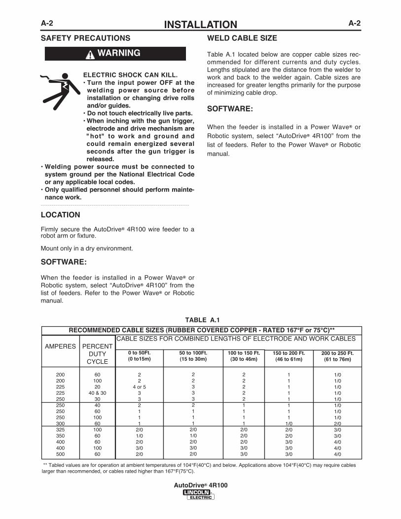
WELD CABLE SIZE
Table A.1 located below are copper cable sizes rec-ommended for different currents and duty cycles.Lengths stipulated are the distance from the welder towork and back to the welder again. Cable sizes areincreased for greater lengths primarily for the purposeof minimizing cable drop.
SOFTWARE:
When the feeder is installed in a Power Wave® orRobotic system, select “AutoDrive® 4R100” from thelist of feeders. Refer to the Power Wave® or Roboticmanual.
WARNING
A-3INSTALLATION
AutoDrive® 4R100
A-3
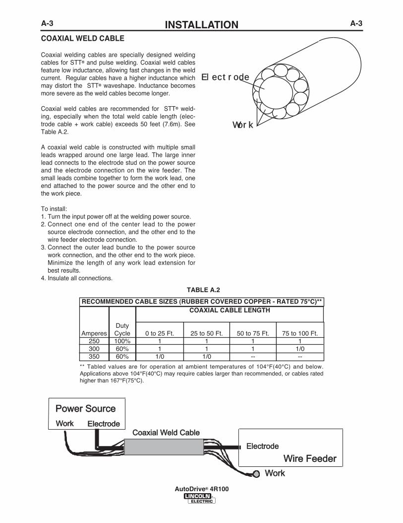
COAXIAL WELD CABLE
Coaxial welding cables are specially designed weldingcables for STT® and pulse welding. Coaxial weld cablesfeature low inductance, allowing fast changes in the weldcurrent. Regular cables have a higher inductance whichmay distort the STT® waveshape. Inductance becomesmore severe as the weld cables become longer.
Coaxial weld cables are recommended for STT® weld-ing, especially when the total weld cable length (elec-trode cable + work cable) exceeds 50 feet (7.6m). SeeTable A.2.
A coaxial weld cable is constructed with multiple smallleads wrapped around one large lead. The large innerlead connects to the electrode stud on the power sourceand the electrode connection on the wire feeder. Thesmall leads combine together to form the work lead, oneend attached to the power source and the other end tothe work piece.
To install:1. Turn the input power off at the welding power source.2. Connect one end of the center lead to the power
source electrode connection, and the other end to thewire feeder electrode connection.
3. Connect the outer lead bundle to the power sourcework connection, and the other end to the work piece.Minimize the length of any work lead extension forbest results.
4. Insulate all connections.
El ect r odeEl ect r ode
Wor kor k
Amperes250300350
DutyCycle100%60%60%
0 to 25 Ft.11
1/0
25 to 50 Ft.11
1/0
50 to 75 Ft.11--
75 to 100 Ft.1
1/0--
COAXIAL CABLE LENGTHRECOMMENDED CABLE SIZES (RUBBER COVERED COPPER - RATED 75°C)**
ElectrodeElectrodeWorkWork
ElectrodeElectrode
WorkWork
Power SourcePower Source
Coaxial Weld CableCoaxial Weld Cable
Wire FeederWire Feeder
TABLE A.2
** Tabled values are for operation at ambient temperatures of 104°F(40°C) and below.Applications above 104°F(40°C) may require cables larger than recommended, or cables ratedhigher than 167°F(75°C).

A-4INSTALLATION
AutoDrive® 4R100
A-4
A
BK
H N L C
DMG
F E
J
I
POWER SOURCE WIRE FEEDER
A
B K
HNLC
DM G
FE
J
I
Function
Motor PowerMotor PowerGas SolenoidGas SolenoidReservedReserved“2A” Differential Tachometer“2B” Differential TachometerReservedReserved“1A” Differential Tachometer“1B” Differential TachometerReserved“67” Electrode Sense Lead
Pin
ABCDEFGHIJKLMN
WIRE DRIVE CABLE, K1785-XXWire drive cables are used to connect power sourcesand control boxes to remote wire drives.
The cables have a 14-pin connector at each end.Both ends of the cable have a collar and thecables cannot be “daisy chained” to make alonger cable.
Function
Motor PowerMotor PowerGas SolenoidGas Solenoid“2A” Differential TachometerReserved+15VDC Tech SupplyTachometer CommonReservedReserved“1A” Differential Tachometer“1B” Differential Tachometer“2B” Differential Tachometer“67” Electrode Sense Lead
Pin
ABCDEFGHIJKLMN
POWER SOURCE WIRE FEEDER
A-5INSTALLATION
AutoDrive® 4R100
A-5
SHIELDING GAS CONNECTION
CYLINDER may explode ifdamaged.
• Keep cylinder upright andchained to support.
• Keep cylinder away from areas where it may bedamaged.
• Never lift welder with cylinder attached.• Never allow welding electrode to touch cylinder.• Keep cylinder away from welding or other live
electrical circuits.• BUILD UP OF SHIELDING GAS MAY
HARM HEALTH OR KILL.• Shut off shielding gas supply when not
in use.• See American National Standard Z-49.1, "Safety
in Welding and Cutting” Published by theAmerican Welding Society.
----------------------------------------------------------------------Maximum inlet pressure is 100 psi. (6.9 bar.)
Install the shielding gas supply as follows:
1. Secure the cylinder to prevent it from falling.
2. Remove the cylinder cap. Inspect the cylinder valvesand regulator for damaged threads, dirt, dust, oil orgrease. Remove dust and dirt with a clean cloth. DONOT ATTACH THE REGULATOR IF OIL, GREASEOR DAMAGE IS PRESENT! Inform your gas supplierof this condition. Oil or grease in the presence of highpressure oxygen is explosive.
3. Stand to one side away from the outlet and open thecylinder valve for an instant. This blows away any dustor dirt which may have accumulated in the valve out-let.
4. Attach the flow regulator to the cylinder valve andtighten the union nut(s) securely with a wrench. Note:if connecting to 100% CO2 cylinder, insert regulatoradapter between regulator and cylinder valve. Ifadapter is equipped with a plastic washer, be sure it isseated for connection to the CO2 cylinder.
WARNING5. Attach one end of the inlet hose to the outlet fitting of
the flow regulator. Attach the other end to the weldingsystem shielding gas inlet. Tighten the union nuts witha wrench.
6. Before opening the cylinder valve, turn the regulatoradjusting knob counterclockwise until the adjustingspring pressure is released.
7. Standing to one side, open the cylinder valve slowly afraction of a turn. When the cylinder pressure gagestops moving, open the valve fully.
8. The flow regulator is adjustable. Adjust it to the flowrate recommended for the procedure and processbeing used before making a weld.

A-6INSTALLATION
AutoDrive® 4R100
A-6
PROCEDURE TO INSTALL DRIVE ROLLSAND WIRE GUIDES
ELECTRIC SHOCK can kill.• Turn the input power OFF at the weld-
ing power source before installationor changing drive rolls and/or guides.
• Do not touch electrically live parts.• When inching with the gun trigger, electrode and
drive mechanism are "hot" to work and groundand could remain energized several secondsafter the gun trigger is released.
• Do not operate with covers, panels or guardsremoved or open.
• Only qualified personnel should perform mainte-nance work.
----------------------------------------------------------------------To remove drive rolls and wire guides:
1. Turn power off at the welding power source.
2. Remove the outer wire guide.
3. Rotate all of the triangular rings to the unlockedposition.
WARNING
4. Open the idle arms.
5. Remove the drive rolls and inner wire guide.
To install drive rolls and wire guides:
1. Turn off power at the welding power source.
2. Open the idle arms.
3. Assemble the inner wire guide.
4. Slide the drive rolls onto the drive hubs.
5. Close the idle arms.
6. Rotate all of the triangular rings to the locked posi-tion.
7. Assemble the outer wire guide.
8. Adjust the pressure arms to the recommendedsetting.
INNER WIRE GUIDE
IDLER ARM OPENED
DRIVE ROLLS
OUTER WIRE GUIDE
A-7INSTALLATION
AutoDrive® 4R100
A-7
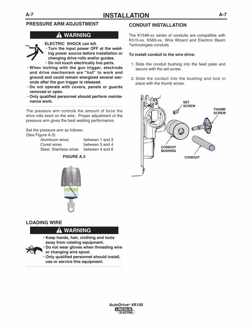
CONDUIT INSTALLATION
The K1546-xx series of conduits are compatible withK515-xx, K565-xx, Wire Wizard and Electron BeamTechnologies conduits.
To install conduit to the wire drive:
1. Slide the conduit bushing into the feed plate andsecure with the set screw.
2. Slide the conduit into the bushing and lock inplace with the thumb screw.
CONDUIT
CONDUITBUSHING
THUMBSCREW
SETSCREW
PRESSURE ARM ADJUSTMENT
ELECTRIC SHOCK can kill.• Turn the input power OFF at the weld-
ing power source before installation orchanging drive rolls and/or guides.
• Do not touch electrically live parts.• When inching with the gun trigger, electrode
and drive mechanism are "hot" to work andground and could remain energized several sec-onds after the gun trigger is released.
• Do not operate with covers, panels or guardsremoved or open.
• Only qualified personnel should perform mainte-nance work.
------------------------------------------------------------------------The pressure arm controls the amount of force thedrive rolls exert on the wire. Proper adjustment of thepressure arm gives the best welding performance.
Set the pressure arm as follows:(See Figure A.3)
Aluminum wires between 1 and 3Cored wires between 3 and 4Steel, Stainless wires between 4 and 6
LOADING WIRE
• Keep hands, hair, clothing and toolsaway from rotating equipment.
• Do not wear gloves when threading wireor changing wire spool.
• Only qualified personnel should install,use or service this equipment.
------------------------------------------------------------------------
WARNING
WARNING
FIGURE A.3

A-8INSTALLATION
AutoDrive® 4R100
A-8
SYSTEM SET-UP
Arc
Lin
k X
TC
onn
ecti
on
Arc
Lin
k(5
Pin
)W
ork
Sen
se
Wir
e F
eed
er(1
4 P
in)
Rob
oti
cT
orc
h
Pow
er W
ave®
i400
K26
69-1
Wo
rk P
iece
FA
NU
C R
-J30
iA C
on
tro
ller
wit
h In
teg
rate
d O
p B
ox
Op
tio
nal W
ork
Sen
se L
ead
(21)
K17
85-X
X W
ire
Fee
der
K88
4-5,
-6
Con
tro
l Cab
le
* W
ork
Cab
le (-
)
Inte
rnal
Arc
Lin
k X
TC
om
mun
icat
ion
* E
lect
rode
Cab
le (+
)
SYSTEM SET-UP (SINGLE ARM)
Wir
e F
eed
er(1
4 P
in)
Gas
Air
Au
toD
rive
® 4
R10
0(W
ith
ou
t C
ove
r S
ho
wn
)A
rcM
ate
100i
C
* R
efer
to
"O
utp
ut
Cab
le G
uid
elin
es"
for
reco
mm
end
ed c
able
siz
e
Ele
ctro
de
K15
05-X
XK
1507
-XX Con
nec
tion

B-1OPERATION
AutoDrive® 4R100
B-1
• ELECTRIC SHOCK CAN KILL.Unless using COLD FEED fea-ture, when feeding with gun trig-ger, the electrode and drivemechanism are always electri-cally energized and couldremain energized several sec-onds after the welding ceases..
• Do not touch electrically live part or electrodewith skin or wet clothing.
• Insulate yourself from work and ground.• Always wear dry insulating gloves.• Do not operate with covers, panels or guards
removed or open.----------------------------------------------------------------------
• FUMES AND GASSES can bedangerous.
• Keep your head out of fumes.• Use ventilation or exhaust to
remove fumes from breathingzone.
----------------------------------------------------------------------• WELDING SPARKS can cause
fire or explosion.• Keep flammable material away.
----------------------------------------------------------------------ARC RAYS can burn.• Wear eye, ear and body protec-
tion.----------------------------------------------------------------------SEE ADDITIONAL WARNING INFORMATIONUNDER ARC WELDING SAFETY PRECAUTIONSAND IN THE FRONT OF THIS OPERATING MAN-UAL.----------------------------------------------------------------------
WARNING
SAFETY PRECAUTIONSREAD AND UNDERSTAND ENTIRE SECTIONBEFORE OPERATING MACHINE.
WIRE FEEDER
POSITIVE OUTPUT
NEGATIVE OUTPUT
INPUT POWER
DIRECT CURRENT
OPEN CIRCUIT VOLTAGE
INPUT VOLTAGE
OUTPUT VOLTAGE
INPUT CURRENT
OUTPUT CURRENT
PROTECTIVEGROUND
WARNING ORCAUTION
U0
U1
U2
I1
I2
GRAPHIC SYMBOLS THAT APPEAR ONTHIS MACHINE OR IN THIS MANUAL

B-2OPERATIONB-2
AutoDrive® 4R100
DEFINITION OF WELDING TERMS
GMAW• Gas Metal Arc welding
FCAW• Flux Core Arc Welding
STT®
• Surface Tension Transfer
PRODUCT DESCRIPTION
The AutoDrive® 4R100 wire feeder is fully controlledand operated by a robot, control box or user interfaceon the power source. Refer to the appropriate manualfor operating the wire drive.
General Physical DescriptionThe AutoDrive® 4R100 wire feeder is powerful yetcompact wire drive for robotic and hard automationapplications.
The MAXTRAC® 4 roll wire drive gives steady feedingof all wire sizes and types. The drive features splitwire guides, tool-less drive roll changing, dual springpressure arms and changeable gun bushings allmounted in a precision die cast aluminum frame. Aright angle gear box efficiently transfers motor powerfor both high torque and high speed.
The AutoDrive® 4R100 are optimized for the FANUCAM100iC arm and is suited for small diameter wires.The small, light weight package maximizes arm speedand working envelope. Quick release mountingmakes for fast servicing of the feeder and torch.
The AutoDrive® 4R100 motor features replaceable,long lasting motor brushes for extended product life.
General Functional DescriptionThe AutoDrive® 4R100 features a dual channel, highresolution tachometer for precision wire feeding bothforwards and in reverse.
For more information go to the following Web site:http://content.lincolnelectric.com/pdfs/products/literature/RoboticFeederSelectionChart.pdf
RECOMMENDED PROCESSES• GMAW• FCAW• STT®
PROCESS LIMITATIONS
K3002-1 AutoDrive® 4R100:• Maximum wire size = .045(1.2mm)
EQUIPMENT LIMITATIONS
K3002-1 AutoDrive® 4R100• Maximum GMAW gun length = 10ʼ (3.1m)• Maximum FCAW gun length = 10ʼ (3.1m)• Maximum wire drive control cable length = 100ft.
(31m)• Robot and power source software may need to be
updated.• Drive rolls are not included with the feeder.• Mounts to FANUC ArcMate100iC arms.• Maximum Conduit Length 50 Ft. (15m).
RECOMMENDED POWER SOURCES
• Power Wave® F355i• Power Wave® 455 (all models)• Power Wave® 455/STT M• Power Wave® 655/ R• Power Wave® i400

C-1ACCESSORIESC-1
AutoDrive® 4R100
WIRE TYPE
Steel Wires:
Cored Wires:
Aluminum Wires:
KITS ELECTRODE SIZE
KP1505-030S .023-.030 (0.6-0.8mm)KP1505-035S .035 (0.9mm)KP1505-040S .040 (1.0mm)KP1505-045S .045 (1.2mm)
KP1505-035C .030-.035" (0.8-0.9mm)KP1505-045C .040-.045" (1.0-1.2mm)
KP1507-3/64A 3/64" (1.2mm)
OPTIONAL KITS AND ACCESSORIES
Includes: 4 V groovedrive rolls and innerwire guide.
Includes: 4 Knurleddrive rolls and innerwire guide.
Includes: 4 polishedU groove drive rolls,outer wire guide andinner wire guide.
DRIVE ROLL KITS 4 ROLL DRIVE

C-2ACCESSORIESC-2
AutoDrive® 4R100
K1500-4
K1500-5
K489-7
K515-xxK565-xx
K1546-1
Gun Receiver Bushing (for gunwith K466-3 Lincoln gun connec-
tors; compatible with Miller® guns.)
Gun Receiver Bushing (compatiblewith Oxo® guns.)
Gun Receiver Bushing (for LincolnFast-Mate guns.)
Wire ConduitWire Conduit
Incoming Bushing, for LincolnConduit .025- 1/16" (0.6 - 1.6mm)
wire. Compatible with ElectronBeam Conduit.
Includes: Gun receiver bush-ing with hose nipple, set screw
and hex key wrench.
Includes: Gun receiver bushingwith hose nipple, 4 guide tubes,set screw and hex key wrench.
Includes: Gun receiver bushingwith trigger connector.
Requires K1546-1Requires K1546-1
Includes: Incoming bushing andhex key wrench.
K1500-1
K1500-2
K1500-3
Gun Receiver Bushing (for gunswith K466-1 Lincoln gun connec-
tors; Innershield® and Subarcguns)
Gun Receiver Bushing (for gunswith K466-2, K466-10 Lincoln gun
connectors; Magnum® 200/300/400guns and compatible with Tweco®
#2-#4)
Gun Receiver Bushing (for gunswith K613-7 Lincoln gun connec-
tors; Magnum® 550 guns and com-patible with Tweco® #5)
Includes: Gun receiver bush-ing, set screw and hex key
wrench.
Includes: Gun receiver bush-ing with hose nipple, set screw
and hex key wrench.
Includes: Gun receiver bush-ing with hose nipple, set screw
and hex key wrench.

C-3ACCESSORIESC-3
AutoDrive® 4R100
K2175-1
K2175-2
K895-2
K836-1
K884-5
K884-6
K1796-xx
K2593-xx
K1785-xx
K2709-xx
K1733-1
500 lb Accu-Pak® Box Payoff Kit
1000 lb Accu-Pak® Box Payoff Kit
Rotary Wire Dispenser
Dereeler Adapter
Accu-Trak® Drum Payoff Kit – 20inch diameter
Accu-Trak® Drum Payoff Kit – 23inch diameter
Coaxial Cables
Coaxial Cables
Wire Drive Cables
Wire Drive Cables
Wire Straightener
Includes: 1 cable of length “xx”feet. 14-pin connectors on
both ends. Cable length can-not be extended by connecting
K1785 cables together.
Includes: 1 cable of length “xx”feet. 14-pin connectors on
both ends. Has collars at bothends. Used with FANUC armsthat have an integrated cable.
Includes: 1 cable of length “xx”feet. 14-pin connectors onboth ends. May be daisychained to make a longer
cable. Used with FANUC armsthat do not have an integrated
cable.
Includes: 1 wire straightener

D-1MAINTENANCED-1
AutoDrive® 4R100
ELECTRIC SHOCK can kill.• Turn the input power OFF at the
welding power source beforeinstallation or changing drive rollsand/or guides.
• Do not touch electrically liveparts.
• When inching with the gun trigger, electrodeand drive mechanism are "hot" to work andground and could remain energized several sec-onds after the gun trigger is released.
• Do not operate with covers, panels or guardsremoved or open.
• Only qualified personnel should perform mainte-nance work.
------------------------------------------------------------------------
WARNING
SAFETY PRECAUTIONS
ROUTINE MAINTENANCE
To Install or remove the AutoDrive® 4R100 for ser-vicing:
See Installation Section of this Instruction Manual.
BRUSHES:
Every 6 months or every 2.5 million arc starts (whichever comes first), inspect the motor brushes. Replaceif shorter than 0.5” (12.7mm).

E-1TROUBLESHOOTINGE-1
AutoDrive® 4R100
If for any reason you do not understand the test procedures or are unable to perform the tests/repairs safely, contact yourLocal Lincoln Authorized Field Service Facility for technical troubleshooting assistance before you proceed.
CAUTION
This Troubleshooting Guide is provided to help youlocate and repair possible machine malfunctions.Simply follow the three-step procedure listed below.
Step 1. LOCATE PROBLEM (SYMPTOM).Look under the column labeled “PROBLEM (SYMP-TOMS)”. This column describes possible symptomsthat the machine may exhibit. Find the listing thatbest describes the symptom that the machine isexhibiting.
Step 2. POSSIBLE CAUSE.The second column labeled “POSSIBLE CAUSE” liststhe obvious external possibilities that may contributeto the machine symptom.
Step 3. RECOMMENDED COURSE OF ACTIONThis column provides a course of action for thePossible Cause, generally it states to contact yourlocal Lincoln Authorized Field Service Facility.
If you do not understand or are unable to perform theRecommended Course of Action safely, contact yourlocal Lincoln Authorized Field Service Facility.
HOW TO USE TROUBLESHOOTING GUIDE
Service and Repair should only be performed by Lincoln Electric Factory Trained Personnel.Unauthorized repairs performed on this equipment may result in danger to the technician andmachine operator and will invalidate your factory warranty. For your safety and to avoid ElectricalShock, please observe all safety notes and precautions detailed throughout this manual.
__________________________________________________________________________
WARNING
ELECTRIC SHOCK can kill.• Turn the input power OFF at the welding power source before installation or changing
drive rolls and/or guides.• Do not touch electrically live parts.• When inching with the gun trigger, electrode and drive mechanism are "hot" to work
and ground and could remain energized several seconds after the gun trigger isreleased.
• Welding power source must be connected to system ground per the National ElectricalCode or any applicable local codes.
• Only qualified personnel should perform maintenance work.
WARNING
Observe all additional Safety Guidelines detailed throughout this manual.

E-2TROUBLESHOOTINGE-2
AutoDrive® 4R100
Observe all Safety Guidelines detailed throughout this manual
If for any reason you do not understand the test procedures or are unable to perform the tests/repairs safely, contact yourLocal Lincoln Authorized Field Service Facility for technical troubleshooting assistance before you proceed.
CAUTION
PROBLEMS(SYMPTOMS)
POSSIBLE CAUSE
RECOMMENDEDCOURSE OF ACTION
The wire feeder does not feed wireand the drive rolls do not spin.
The wire feeds erratically.
No shielding gas
1. Verify the power source is turnedon.
2. Verify the circuit breaker for thewire feeder on the power sourcehas not tripped.
3. Verify power is being supplied tothe wire feeder.
1. Verify the correct drive rolls andinner wire guide are installed inthe wire drive.
2. Check for sharp bends in the gunliner or conduit.
3. Examine the contact tip for wearand proper size. Replace as nec-essary.
4. Check the gun liner and conduit.The welding electrode shouldslide easily through both.
5. Verify the proper gun liner isinstalled.
6. Verify the pressure arms are setproperly. Too much pressure maycrush the wire.
7. Inspect the motor for worn brush-es.
1. Verify the gas supply is turned onand not empty.
2. Check the gas hose for cuts.Make sure it is not crushed.
3. Verify the shielding gas hose isconnected to the gun bushing orwelding gun.

E-3TROUBLESHOOTINGE-3
AutoDrive® 4R100
Observe all Safety Guidelines detailed throughout this manual
If for any reason you do not understand the test procedures or are unable to perform the tests/repairs safely, contact yourLocal Lincoln Authorized Field Service Facility for technical troubleshooting assistance before you proceed.
CAUTION
PROBLEMS(SYMPTOMS)
POSSIBLE CAUSE
RECOMMENDEDCOURSE OF ACTION
Variable or "hunting" arc.
The motor overload errors occur.
1. Check for proper size contact.Make sure the contact tip is notworn, free of spatter and not melt-ed.
2. Clean and tighten all electrodeand work connections.
3. Verify the proper polarity is beingused for the weld procedure.
4. Make sure the proper electrodestick-out is being maintained.
5. Check the gas flow rate and mix-ture.
6. Verify the gun bushing is tightlymounted to the wire drive.
7. Verify the gun is tightly mountedto the gun bushing.
8. Verify the electrode lead is con-nected to the proper connectionblock on the feed head.
9. Inspect the motor for worn brush-es.
1. Check for sharp bends in the gunliner and conduit.
2. Examine the contact tip for wearand proper size. Replace as nec-essary.
3. Check the gun liner and conduit.The welding electrode shouldslide easily through both.
4. Verify the proper gun liner isinstalled.
5. Reduce the pressure arm setting.
Output Problems

F-1DIAGRAMSF-1
AutoDrive® 4R100
M 2
1562
WIR
ING
DIA
GR
AM
A
UT
OD
RIV
E 4
R22
0 F
EE
DE
R
C
GN
D
6767
B
553
552
550
551
846A
845A
P4
1 2 3 4
846A
845A
WH
ITE
BLA
CK
RED
BRO
WN
YELL
OW
ROY WH
ITE
BLA
CK55
255
3BL
ACK
GRE
ENRE
DBL
ACK
BLA
CK
67A
BLA
CKRE
D
GRE
EN
550
ORA
NG
E53
5
535
531
534
87654321
87
65
43
21
(J800)
58
N.A.
14
537
(J801)
41
N.A.
85
843A
842A
500A
515A
NO
TES:
N.A
. C
AV
ITY
NU
MBE
RIN
G S
EQU
ENCE
AS
VIEW
ED
FRO
M C
OM
PON
ENT
SID
E O
F PC
BO
ARD
. N
.B.
CA
VIT
Y N
UM
BERI
NG
SEQ
UEN
CE A
S VI
EWED
FR
OM
LEA
D S
IDE
OF
CO
NN
ECTO
R.
ELEC
TRIC
AL
SYM
BOLS
PER
E15
37
LEA
D C
OLO
R CO
DIN
G
B –
BLA
CK
W –
WH
ITE
O –
ORA
NG
E Y
– YE
LLO
W
BR –
BRO
WN
R
– RE
D
553A
GA
SSO
LEN
OID
551A
843A
842A
515A
500A
553A
552A
550A
551
1 2 3 4 5 6 7 8P3
NMLKJIHGFEDCBJ2 A
L1
L2
1 2 3 4 5 6 755
0A55
1A
534
537
BR WB
B
531
TACH
WMO
TOR
/G
EARB
OX
8P1FE
EDPL
ATE
TACH
INTE
RFA
CE P
C BD
552A
NO
TE:
This
dia
gra
m i
s fo
r re
fere
nce
only
.
It m
ay
not
be a
ccura
te f
or
all
mach
ines
cove
red b
y th
is m
anual.
The s
peci
fic
dia
gra
m f
or
a p
art
icula
r co
de i
s past
ed i
nsi
de t
he m
ach
ine o
n o
ne
of
the e
ncl
osu
re p
anels
. I
f th
e d
iagra
m i
s il
legib
le,
wri
te t
o t
he S
erv
ice D
epart
ment
for
a r
epla
cem
ent.
G
ive t
he e
quip
ment
cod
e n
um
be
r.

F-2DIMENSION PRINTF-2
AutoDrive® 4R100
6.02
”
4.72
”
3.02
”
7.50
”
3.50
”
8.35
”
9.02
”
8.02
”
0.27
”
0.62
”
0.62
”1.
97”
1.97
”1.
78”
1.46
”
1.00
”
1.56
”
LIN
CO
LN
E
LE
CT
RIC

NOTES
AutoDrive® 4R100

NOTES
AutoDrive® 4R100

NOTES
AutoDrive® 4R100

WARNING
AVISO DEPRECAUCION
ATTENTION
WARNUNG
ATENÇÃO
Spanish
French
German
Portuguese
Japanese
Chinese
Korean
Arabic
READ AND UNDERSTAND THE MANUFACTURER’S INSTRUCTION FOR THIS EQUIPMENT AND THE CON-SUMABLES TO BE USED AND FOLLOW YOUR EMPLOYER’S SAFETY PRACTICES.
SE RECOMIENDA LEER Y ENTENDER LAS INSTRUCCIONES DEL FABRICANTE PARA EL USO DE ESTEEQUIPO Y LOS CONSUMIBLES QUE VA A UTILIZAR, SIGA LAS MEDIDAS DE SEGURIDAD DE SU SUPER-VISOR.
LISEZ ET COMPRENEZ LES INSTRUCTIONS DU FABRICANT EN CE QUI REGARDE CET EQUIPMENT ETLES PRODUITS A ETRE EMPLOYES ET SUIVEZ LES PROCEDURES DE SECURITE DE VOTREEMPLOYEUR.
LESEN SIE UND BEFOLGEN SIE DIE BETRIEBSANLEITUNG DER ANLAGE UND DEN ELEKTRODENEIN-SATZ DES HERSTELLERS. DIE UNFALLVERHÜTUNGSVORSCHRIFTEN DES ARBEITGEBERS SIND EBEN-FALLS ZU BEACHTEN.
Do not touch electrically live parts orelectrode with skin or wet clothing.Insulate yourself from work andground.
No toque las partes o los electrodosbajo carga con la piel o ropa mojada.Aislese del trabajo y de la tierra.
Ne laissez ni la peau ni des vêtementsmouillés entrer en contact avec despièces sous tension.Isolez-vous du travail et de la terre.
Berühren Sie keine stromführendenTeile oder Elektroden mit IhremKörper oder feuchter Kleidung!Isolieren Sie sich von den Elektrodenund dem Erdboden!
Não toque partes elétricas e electro-dos com a pele ou roupa molhada.Isole-se da peça e terra.
Keep flammable materials away.
Mantenga el material combustiblefuera del área de trabajo.
Gardez à l’écart de tout matérielinflammable.
Entfernen Sie brennbarres Material!
Mantenha inflamáveis bem guarda-dos.
Wear eye, ear and body protection.
Protéjase los ojos, los oídos y elcuerpo.
Protégez vos yeux, vos oreilles etvotre corps.
Tragen Sie Augen-, Ohren- und Kör-perschutz!
Use proteção para a vista, ouvido ecorpo.

WARNING
AVISO DEPRECAUCION
ATTENTION
WARNUNG
ATENÇÃO
Spanish
French
German
Portuguese
Japanese
Chinese
Korean
Arabic
LEIA E COMPREENDA AS INSTRUÇÕES DO FABRICANTE PARA ESTE EQUIPAMENTO E AS PARTES DEUSO, E SIGA AS PRÁTICAS DE SEGURANÇA DO EMPREGADOR.
Keep your head out of fumes.Use ventilation or exhaust to removefumes from breathing zone.
Los humos fuera de la zona de res-piración.Mantenga la cabeza fuera de loshumos. Utilice ventilación oaspiración para gases.
Gardez la tête à l’écart des fumées.Utilisez un ventilateur ou un aspira-teur pour ôter les fumées des zonesde travail.
Vermeiden Sie das Einatmen vonSchweibrauch!Sorgen Sie für gute Be- undEntlüftung des Arbeitsplatzes!
Mantenha seu rosto da fumaça.Use ventilação e exhaustão pararemover fumo da zona respiratória.
Turn power off before servicing.
Desconectar el cable de alimentaciónde poder de la máquina antes de ini-ciar cualquier servicio.
Débranchez le courant avant l’entre-tien.
Strom vor Wartungsarbeiten abschal-ten! (Netzstrom völlig öffnen;Maschine anhalten!)
Não opere com as tampas removidas.Desligue a corrente antes de fazerserviço.Não toque as partes elétricas nuas.
Do not operate with panel open orguards off.
No operar con panel abierto oguardas quitadas.
N’opérez pas avec les panneauxouverts ou avec les dispositifs deprotection enlevés.
Anlage nie ohne Schutzgehäuse oderInnenschutzverkleidung in Betriebsetzen!
Mantenha-se afastado das partesmoventes.Não opere com os paineis abertos ouguardas removidas.

CUSTOMER ASSISTANCE POLICY
The business of The Lincoln Electric Company is manufacturing andselling high quality welding equipment, consumables, and cuttingequipment. Our challenge is to meet the needs of our customers andto exceed their expectations. On occasion, purchasers may askLincoln Electric for advice or information about their use of ourproducts. We respond to our customers based on the best informationin our possession at that time. Lincoln Electric is not in a position towarrant or guarantee such advice, and assumes no liability, withrespect to such information or advice. We expressly disclaim anywarranty of any kind, including any warranty of fitness for anycustomer’s particular purpose, with respect to such information oradvice. As a matter of practical consideration, we also cannot assumeany responsibility for updating or correcting any such information oradvice once it has been given, nor does the provision of informationor advice create, expand or alter any warranty with respect to the saleof our products.
Lincoln Electric is a responsive manufacturer, but the selection anduse of specific products sold by Lincoln Electric is solely within thecontrol of, and remains the sole responsibility of the customer. Manyvariables beyond the control of Lincoln Electric affect the resultsobtained in applying these types of fabrication methods and servicerequirements.
Subject to Change – This information is accurate to the best of ourknowledge at the time of printing. Please refer to www.lincolnelectric.com for any updated information.


