OPERATORS MANUAL...APRIL 2018 CAT.# PD-OM-A/S 04/01/18 ATI Corporation New Holland, PA 17557 Phone...
40
APRIL 2018 CAT.# PD-OM-A/S 04/01/18 ATI Corporation New Holland, PA 17557 Phone (717) 354-8721 • FAX (717) 354-2162 1-800-342-0905 www.level-best.com OPERATORS MANUAL PD - SERIES PARA-LEVEL DUAL APACHE/SPECTRA
Transcript of OPERATORS MANUAL...APRIL 2018 CAT.# PD-OM-A/S 04/01/18 ATI Corporation New Holland, PA 17557 Phone...

APRIL 2018CAT.# PD-OM-A/S 04/01/18
ATI CorporationNew Holland, PA 17557
Phone (717) 354-8721 • FAX (717) 354-21621-800-342-0905
www.level-best.com
OPERATORS MANUALPD - SERIES PARA-LEVEL DUAL
APACHE/SPECTRA


i
COPYRIGHT 2018 byATI Corporation250 Earland DriveNew Holland, PA 17557 U.S.A.
DISCLAIMERTHE INFORMATION IN THIS MANUAL IS PROVIDED TO PROMOTE THE SAFE USE OF, AND ASSIST THE OPERATOR IN ACHIEVING THE BEST PERFORMANCE FROM, PARA-LEVEL GRADING BOX DESCRIBED HEREIN, FOR THEIR INTENDED APPLICATIONS.

ii
NOTES

iii
TABLE OF CONTENTSNOTES ..............................................................................................................................................................iiTABLE OF CONTENTS .................................................................................................................................iiiSAFETY INFORMATION ...............................................................................................................................v
Safety Precaution Definitions ....................................................................................................................vWARRANTY ...................................................................................................................................................viLIST OF ILLUSTRATIONS ..........................................................................................................................viiLIST OF TABLES .........................................................................................................................................viiiSYSTEMS FEATURES AND BASIC OPERATION ......................................................................................1
Purpose ......................................................................................................................................................1Components ...............................................................................................................................................1Control Panel .............................................................................................................................................2
Controls ..............................................................................................................................................2Operation ............................................................................................................................................5
Rotating Laser ..........................................................................................................................................10Laser Receiver ......................................................................................................................................... 11Cables ...................................................................................................................................................... 11Equipment Setup ......................................................................................................................................14Hydraulics ................................................................................................................................................16
Danfoss PVG-32 Hydraulic Valve ....................................................................................................16Hydraulic Hose Connection .............................................................................................................16
Job Site Set-Up ........................................................................................................................................16Set-Up for Level Grading .................................................................................................................17Set-Up for Sloped Grading ...............................................................................................................17
Benching And Operating .........................................................................................................................19Benching ...........................................................................................................................................19Benching with a Rod Eye .................................................................................................................20Operation ..........................................................................................................................................20
TROUBLESHOOTING ..................................................................................................................................22SPECIFICATIONS AND MAINTENANCE .................................................................................................25
Maintenance .............................................................................................................................................25Storage and Transport .......................................................................................................................25Cleaning ............................................................................................................................................25Cables and Hoses ..............................................................................................................................25Machine ............................................................................................................................................25Calibration ........................................................................................................................................25Loader Hydraulics ............................................................................................................................25

iv
Service .....................................................................................................................................................25Specifications ...........................................................................................................................................26
Dimensions .......................................................................................................................................26Control Panel CB52 ..........................................................................................................................26Laser Receiver Bullseye B5M ..........................................................................................................26
INDEX ............................................................................................................................................................28
TABLE OF CONTENTS

v
This manual is furnished to you, the owner/opera-tor, as a guide to get the greatest benefit from your Grading Box. ATI Corporation wants you to be able to get the most use out of your grading box through safe and efficient operation.Before attempting to operate the grading box, carefully read all sections of this manual. Be sure that you thoroughly understand all of the safety information and operating procedures.
SAFETY PRECAUTION DEFINITIONSDangers, Warnings, Cautions, and Notes are strategically placed throughout this manual to fur-ther emphasize the importance of personal safety, qualifications of operating personnel, and proper use of the grading box in its intended application. These precautions supplement and/or complement the safety information decals affixed to the unit and include headings that are defined as follows:
Indicates an imminently hazardous situation which, if not avoided, will result in death or serious injury.
Indicates a potentially hazardous situation or practice which, if not avoided, could result in death or serious injury.
Indicates a potentially hazardous situation or practice which, if not avoided, will result in damage to equipment and/or minor injury.
NOTE: Indicates an operating procedure, practice. etc., or portion thereof, which is essential to highlight.
• Always use caution and safe operating prac-tices when operating this equipment.
• Always set the Automatic/Manual Switch on the Control Panel to MANUAL before leaving the operator’s seat or whenever the machine is not moving.
SAFETY INFORMATION• Always allow for clearance under the cutting
edge of the machine when tuning the system or when switching to automatic control. Insufficient clearance could cause the machine to lift itself off the ground as its cutting edge attempts to achieve the programmed slope.
• Never adjust the position of the laser receiver when the system is in automatic control.
• Never perform service work on your machine or the Automatic Control System when the system is in automatic control.
• Install all safety panels and guards before operating your equipment.
• Stay clear of all moving parts when the machine is in operation.
• Keep all people clear of the machine when it is running.
• Keep feet and other body parts from under the cutting edges of the machine at all times.
• Read and comply with all safety recommenda-tions of your tractor/skid steer manufacturer, as outlined in its operator and service manuals.
NOTE: References made to left, right, front, and rear are those directions viewed from be-hind the power unit and grading box.
NOTE: Some equipment depicted in illustrations may not reflect exact production model configurations.
NOTE: All safety, operating, and servicing infor-mation reflects current production models at the time of publication of this manual.
NOTE: ATI Corporation reserves the right to discontinue models at any time, change specifications, and improve design without notice and without incurring obligation on goods previously purchased and to discon-tinue supplying any part listed, when the demand does not warrant production.

vi
WARRANTY This Level-Best Grading System is designed and manufactured to high standards. ATI Corporation, therefore, guarantees this Level-Best product to be free from defect in workmanship and materials for three (3) years from purchase date. If the machine is to be used for rental purposes the warranty is limited to ninety (90) days.
Components supplied by outside vendors (e.g. cylinders, hydraulic valves and components, elec-tronic modules, and machine control technology systems) are warranted separately by their respec-tive manufacturers. The warranty periods of these components are generally one (1) year from date of purchase.
Neither Level-Best nor hydraulic component manufacturers will cover normal wear or fail-ure due to hydraulic oil contamination from the power source. ALWAYS start with clean oil and filters prior to installation and operation.
Misuse, abuse, misapplication, and unauthorize alterations will void this warranty.
All warranty work must be performed by an authorized Level-Best dealer and authorized by ATI Corporation. All Level-Best parts suspected of failure must be returned to ATI Corporation for warranty analysis prior to any credit being issued.

vii
LIST OF ILLUSTRATIONSFigure 1. Plane of Laser Light with Components of the Automatic Control System ....................................1Figure 2. Front View of the Control Panel ....................................................................................................3Figure 3. Rear View of the Control Panel .....................................................................................................4Figure 4. Control Panel Display ....................................................................................................................4Figure 5. Receiver Position Indicator ............................................................................................................4Figure 6. LED Grade Display ........................................................................................................................5Figure 7. User Setup Screen ..........................................................................................................................7Figure 8. LCD Brightness and Contrast Edit Mode ......................................................................................8Figure 9. Deadband Edit Mode .....................................................................................................................8Figure 10. Valve Speed Edit Mode ..................................................................................................................8Figure 11. Reference Elevation Edit Mode .....................................................................................................9Figure 12. Units of Measure Edit Mode ..........................................................................................................9Figure 13. Store and Recall Edit Mode ...........................................................................................................9Figure 14. Rotating Laser ..............................................................................................................................10Figure 15. Bullseye B5M .............................................................................................................................. 11Figure 16. Power Cable .................................................................................................................................12Figure 17. Receiver Junction Cable ..............................................................................................................12Figure 18. Receiver Cable .............................................................................................................................12Figure 19. Solenoid Cable .............................................................................................................................13Figure 20. Remote Switch Cable ...................................................................................................................13Figure 21. Control Panel Mounting ...............................................................................................................14Figure 22. Components of the Automatic Control System on a Skid Steer ..................................................15Figure 23. Junction Block and Laser Receiver Cables ..................................................................................15Figure 24. Hydraulic Valve (Danfoss PVG-32) ............................................................................................16Figure 25. Hydraulic Hose Connections to Skid Steer ..................................................................................16Figure 26. Method One: Align Rotating Laser with Grade Stakes ...............................................................17Figure 27. Sight Over Rotating Laser ...........................................................................................................17Figure 28. Grade Stake with Elevation Mark ................................................................................................18Figure 29. Method Two: Align Rotating Laser with Grade Stakes ...............................................................18Figure 30. Benching the Para-Level LGB with a Level Plane ......................................................................19Figure 31. Lube and Maintenance Chart .......................................................................................................27

viii
LIST OF TABLESTable 1. Units ...................................................................................................................................................9
1
SYSTEMS FEATURES AND BASIC OPERATION
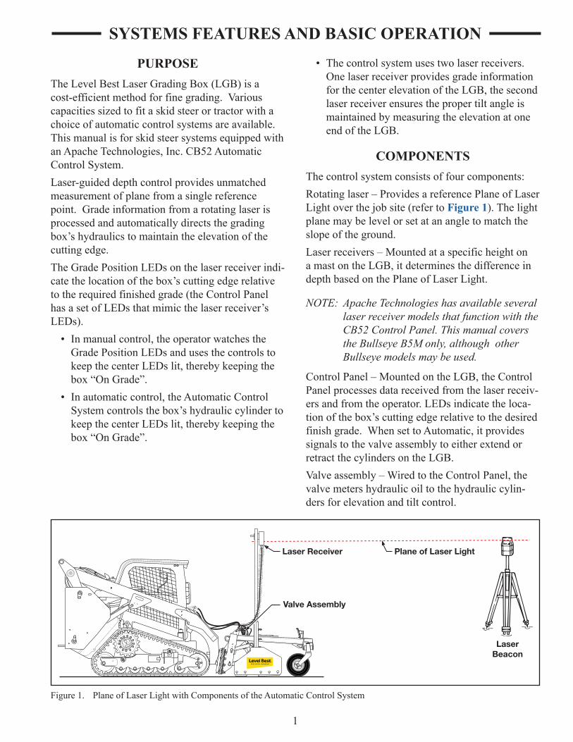
PURPOSEThe Level Best Laser Grading Box (LGB) is a cost-efficient method for fine grading. Various capacities sized to fit a skid steer or tractor with a choice of automatic control systems are available. This manual is for skid steer systems equipped with an Apache Technologies, Inc. CB52 Automatic Control System.Laser-guided depth control provides unmatched measurement of plane from a single reference point. Grade information from a rotating laser is processed and automatically directs the grading box’s hydraulics to maintain the elevation of the cutting edge.The Grade Position LEDs on the laser receiver indi-cate the location of the box’s cutting edge relative to the required finished grade (the Control Panel has a set of LEDs that mimic the laser receiver’s LEDs).
• In manual control, the operator watches the Grade Position LEDs and uses the controls to keep the center LEDs lit, thereby keeping the box “On Grade”.
• In automatic control, the Automatic Control System controls the box’s hydraulic cylinder to keep the center LEDs lit, thereby keeping the box “On Grade”.
• The control system uses two laser receivers. One laser receiver provides grade information for the center elevation of the LGB, the second laser receiver ensures the proper tilt angle is maintained by measuring the elevation at one end of the LGB.
COMPONENTSThe control system consists of four components:Rotating laser – Provides a reference Plane of Laser Light over the job site (refer to Figure 1). The light plane may be level or set at an angle to match the slope of the ground.Laser receivers – Mounted at a specific height on a mast on the LGB, it determines the difference in depth based on the Plane of Laser Light.
NOTE: Apache Technologies has available several laser receiver models that function with the CB52 Control Panel. This manual covers the Bullseye B5M only, although other Bullseye models may be used.
Control Panel – Mounted on the LGB, the Control Panel processes data received from the laser receiv-ers and from the operator. LEDs indicate the loca-tion of the box’s cutting edge relative to the desired finish grade. When set to Automatic, it provides signals to the valve assembly to either extend or retract the cylinders on the LGB.Valve assembly – Wired to the Control Panel, the valve meters hydraulic oil to the hydraulic cylin-ders for elevation and tilt control.
Valve Assembly
Laser Receiver
LaserBeacon
Plane of Laser Light
Figure 1. Plane of Laser Light with Components of the Automatic Control System

2
NOTE: The CB52 Control Panel can be configured several different ways. This manual as-sumes the ATI factory default setting dis-playing the center laser receiver data, or elevation, on the left side of the LCD and right-side laser receiver data, or tilt, on the right side of the LCD. Apache Technologies references this as dual elevation mode be-cause both laser receivers reference eleva-tion and the LCD displays elevation data.
Controls
A remote switch is inside the skid steer loader's operator station. This switch is used for operation of the raise, lower, and tilt functions and selec-tion of automatic or manual control. Refer to the section on Equipment Setup for more information regarding proper installation of the remote switch.
NOTE: This manual refers only to the joysticks on the control panel. Any action or motion required by the joysticks can be assumed to cause the same function/reaction when us-ing the remote switch, provided the remote switch has been mounted in the correct orientation.
The following identifies the indicators, switches and type of switch on the Control Panel.
In addition, wires and cables to connect the compo-nents are included with the unit. A remote switch provides control from within the skid steer loader’s operator station while maintaining visible contact of the Control Panel screen mounted on the LGB.
CONTROL PANELThe Control Panel is essentially a computer with built-in logic for the inputs and outputs connected to it. The Control Panel provides many adjustments to allow compatibility with different machinery and application requirements.The Control Panel uses an LCD screen to provide information to the operator. One side of the screen displays elevation, or blade depth, at the center of the LGB and other side is for elevation at the right-side of the blade.Selections are made via two multiple-function switches (joysticks) that move up or down and left or right, can be rotated in either direction, and pressed. Between each joystick and the power switch is a support, or hand rest, to help steady the operator's hand as he moves the controls. Grade LEDs are used to indicate direction of grade.The laser receiver located on the right side of the LGB controls the tilt, or slope, of the cutting edge by measuring elevation of the grade at a different location than the center laser receiver.
NOTE: This manual references the Para-Level LGB’s ability to follow slope. This does not imply that a slope laser receiver is required to provide this functionality. The tilt capa-bility is obtained by measuring elevation at two different positions relative to the rotat-ing laser.
The Control Panel has two modes accessible to the user; Operation and User Setup. In User Setup mode, items such as valve speed and LCD bright-ness can be adjusted. Operation mode allows operation of the Para-Level LGB either automati-cally, with the Control Panel controlling depth and tilt, or manually, with the operator controlling the depth and tilt.
SYSTEMS FEATURES AND BASIC OPERATION

3
Front Control Panel Switches
Access Panel
12 13 14
1
678
9
4
5
33
10
211
6
Figure 2. Front View of the Control Panel
1. LCD Display – Indicates the various opera-tion and configuration modes. The displayed items change based on the mode and User Setup parameters chosen. Refer to the section on LCD display for more specific information.
2. LED Grade Display for Tilt Function – Indicates where the cutting edge is in relation to the on-grade position. Refer to the section on Grade Indicators for more information.
3. Mounting Knobs – Secures the control panel to the mounting brackets on the Para-Level LGB.
4. Auto/Manual LED for Tilt – Green “A” LED illuminates when in Automatic operation and amber “M” LED illuminates when in Manual operation.
5. Tilt Joystick – Left/right movement selects Auto/Manual control for the slope function and up/down movement tilts the blade. Rotation increases/decreases the control
setpoint. Pressing “in” enables elevation and slope matching. When released, the joystick returns to a center, neutral position.
This joystick also navigates through the User Setup menus.
6. Access Panel Screws – Retains access panel to the Control Panel.
7. Access Panel – Panel contains a fuse, rotary switch and DIP switch used in factory setups.
8. Power Switch – Turns power on and off. Also provides access to Help screens by pressing up while operating.
9. Elevation Joystick – Left/right movement selects Auto/Manual control for the eleva-tion function and up/down movement raises and lowers the blade. Rotation increases/decreases the control setpoint. Pressing “in” enables elevation and slope matching. When released, the joystick returns to a center, neutral position.
This joystick also navigates through the User Setup menus.
10. Auto/Manual LED for Elevation – Green “A” LED illuminates when in Automatic operation and amber “M” LED illuminates when in Manual operation.
11. LED Grade Display for Elevation Function – Indicates where the cutting edge is in relation to the on-grade position. Refer to the section on Refer to the section on Grade Indicators for more information.
Do not change or modify the Rotary or DIP switch positions. These switches are set at the factory before shipment. Contact the installa-tion technician for additional information, if required.
12. Rotary Switch – Used for factory setup. Do not adjust this unless directed to by ATI Corporation service department.
SYSTEMS FEATURES AND BASIC OPERATION

4
13. DIP Switch – Used for factory setup. Do not adjust unless directed to by ATI Corporation service department.
14. Fuse – Automotive-style, 25-amp fuse protects against power surges.
Rear Control Panel Connections
18 15
1620
19
17
Figure 3. Rear View of the Control Panel
15. Remote Switch – 7-pin connector for the remote switch wire harness.
16. Hydraulic Valve Output – 10-pin connector for the valve wire harness.
17. Machine Power Input – 4-pin connector for the power wire harness.
18. Laser Receiver – 7-pin connector for laser receiver input. This connects to the junction box.
19. Beeper – Beeper for audible indication of alarms and switch engagement. A single beep is activated when a switch command is accepted. A double beep is activated when a selected function is not available or is incorrect. Beeper volume can be adjusted by rotating the beeper.
20. Serial Number Plate – Records build and model data for troubleshooting purposes.
Control Panel Display
The Control Panel Display provides information to the operator for efficient control of the LGB in either Automatic or Manual mode. Inputs from the joystick located on the left side are displayed on the left side of the screen and vice-versa.
The default ATI Corporation setup of the Para-Level LGB with control system displays data as two different elevations. Elevation information for the center laser receiver is shown on the left side of the Control Panel LCD and elevation information for the right laser receiver is shown on the right side of the LCD.
NOTE:`The right laser receiver is sometimes referred to as a slope or tilt receiver be-cause it controls the hydraulic cylinder which allows the Para-Level LGB to create a sloped grade. However, actual data is based on elevation, not slope.
1
2
5
69810 7
Figure 4. Control Panel Display
1. Reference Elevation – Indicates the refer-ence elevation. The value is referenced from the last bench mark.
2. Units – Displays the units of the reference elevation. Can be changed in User Setup mode.
3
4
Figure 5. Receiver Position Indicator
SYSTEMS FEATURES AND BASIC OPERATION

5
3. Receiver Position Indicator – Indicates the elevation relative to the vertical reception range of the receiver. The + indicator blinks when reception is lost.
The on-grade set range will vary depending on the width of the deadband. The smaller the deadband, the larger the range. The larger the deadband, the smaller the range.
4. Control Setpoint – Indicates where on-grade is set relative to the vertical reception range.
5. Automatic/Manual Indicator – Indicates if the control system is in manual (M) or automatic (A) mode.
6. Joystick Function Icon – Indicates the current mode of the joystick. Pressing the joystick alternates control between slope matching/benching and slope control set-point.
7. Raise/Lower Indicator – Indicates the direc-tion of movement of the blade.
8. Operating Mode Indicator – Indicates the operating mode of each side of the Control Panel. Dual elevation control is shown.
9. Control Source Indicator – Indicates the source of control. Starburst icon indicates input is being received from a laser receiver.
10. Linked/Unlinked Elevation Mode – Only used in dual elevation mode.
Grade Indicators
On each side of the LCD is a grade indicator. The grade indicator is a set of red and green LEDs that indicate relative position to grade. When a laser is striking the receiver, there are five possible posi-tions of grade information indicated.
High Coarse - Three top red LED’s forming a down arrow.
High Fine - Three top red LED’s and three green on-grade LED’s.
On-Grade - Three green LED’s forming horizon-tal bar.
Low Fine - Three bottom red LED’s and three green on-grade LED’s.
Low Coarse - Three bottom red LED’s forming an up arrow.
HighCourse
HighFine
OnGrade
LowFine
LowCourse
Figure 6. LED Grade Display
If the laser moves off the reception range of the receiver, an out-of-beam indication appears on the LEDs. If the last laser reception was on the bottom of the receiver, the top three LEDs flash indicating to move the receiver down. If the last laser recep-tion was on the top, the bottom three LEDs flash indicating to move the receiver up. The out-of-beam indication lasts for two minutes.
Operation
Control of the Para-Level LGB is accomplished through the Control Panel. The operator places the system in either Automatic control, where the system raises/lower/tilts the LGB based on inputs from the laser system, or Manual control, where the operator moves the LGB using the controls on the Control Panel (or remote switch).
Always set the system to Manual control before leaving the skid steer loader. Move both joy-sticks toward the middle (inward) to activate Manual control.
To turn the system on, toggle the Power switch to the I (on) position. The LEDs and LCD will light to confirm power. The Control Panel will perform a diagnostic check to ensure the system compo-nents are present and responding correctly. If the laser receivers are present, the LEDs on the receiv-ers will light as a system check. If components are not found, a “No Receivers Found” message is displayed.
NOTE: The system must be restarted if receivers or components are connected or added.
SYSTEMS FEATURES AND BASIC OPERATION

6
Automatic/Manual Control
To place the Para-Level LGB under Automatic control, move the left joystick to the left (outward) and the right joystick to the right (out-ward) and release each to neutral. The green “A” LEDs on the Control Panel illuminate to indicate Automatic control.Under Automatic control, the Control Panel sends the appropriate signals to the valve to raise/lower/tilt the LGB to obtain and maintain an on-grade position. If the receiver is outside the range of the laser signal, it must be moved within range to start receiving signals.To place the Para-Level LGB under Manual control, move the left joystick to the right (inward) and the right joystick to the left (inward) and release each to neutral. The amber “M” LEDs on the Control Panel illuminate to indicate Manual control.Under Manual control, the LED Grade Display will indicate grade information but will not send adjustment signals to the valve. Adjustment of the LGB elevation and slope must be accomplished manually.
Raise/Lower
The left-side joystick raises or lowers the LGB when under Manual control. Move the joystick up to raise the blade and down to lower the blade.When under Automatic control, the left-side
joystick will temporarily raise or lower the LGB. When the joystick is released, the LGB returns to Automatic control.
Tilt
The right-side joystick adjusts the slope angle of the LGB when under Manual control. When under Automatic control, the right-side joystick will temporarily change the slope angle of the LGB. When the joystick is released, the LGB returns to Automatic control.
Elevation/Slope Offset (Reference Adjustment)
The CB52 has the capability to adjust the on-grade point without adjusting the laser receiver(s) to within one inch of the end of its range. This feature can be used to raise the grade for initial rough-cut and then return the LGB to desired grade for finishing.The on-grade reference point is adjusted from the Control Panel by rotating the appropriate joystick. Rotate the joystick clockwise to increase the eleva-tion, counterclockwise decreases the elevation. The offset will not go beyond a limit programmed into the laser receiver.When the reference is adjusted, the LCD displays the actual elevation change from the benchmark.If linking is enabled, either joystick can be rotated and the on-grade reference is adjusted equally for both elevation and tilt. When under Automatic control, the LGB will begin to move immediately. When under Manual control, the blade will not move until placed under Automatic control.
Elevation/Slope Matching
Elevation/Slope matching allows the current laser signal to be temporarily set to the on-grade reference. This allows adjustment of the on-grade elevation for an initial cut of the area to be graded at a set distance above the engineered plane.When the laser strike signal is within range of the laser receiver and at least one inch from the outer limit, press and hold the appropriate joystick for approximately one second and release when a single beep is heard from the Control Panel. The LCD and grade LEDs will indicate the LGB is on-grade. If outside the acceptable laser receiver range, two beeps are sounded to indicate the com-mand was not accepted.
SYSTEMS FEATURES AND BASIC OPERATION
7
SYSTEMS FEATURES AND BASIC OPERATIONTo reset the elevation to the default center on-grade position, press and hold the joystick for five seconds. The first beep is heard at approximately one second and the second beep is heard at five seconds, when the elevation is reset to the default. The elevation control setpoint returns to the center position and the LCD indicates the elevation in relation to the default.
Link
The Link capability within the Control Panel allows the two different elevations of the LGB to be adjusted/moved simultaneously. When activated, this function applies to changing Automatic/Manual control, adjusting elevation offset, and adjusting or resetting the elevation matching features.Before linking, set the LGB in the desired position to ensure the relative positioning of the two laser receivers. This is usually parallel to the laser plane. With the Control Panel in dual elevation mode (default), move both joysticks inward (manual posi-tion) and hold for three seconds. The link icon on the LCD changes from a broken link to a connected link (chain).
Audio Alerts
The beeper on the back of the Control Panel can be rotated to adjust the volume of the tones emitted.A single, short beep is sounded to indicate an input, or command, is accepted. A double beep indicates a command was not accepted. A triple beep is sounded when the Control Panel is first powered up.
User Setup
When purchased from ATI Corporation with the Para-Level LGB, the control system is setup specifically for the unit purchased. Some items may be customized to suit the operator’s specific needs or operating conditions. Up to three separate configurations can be saved. A fourth configuration returns the unit to the factory default settings.
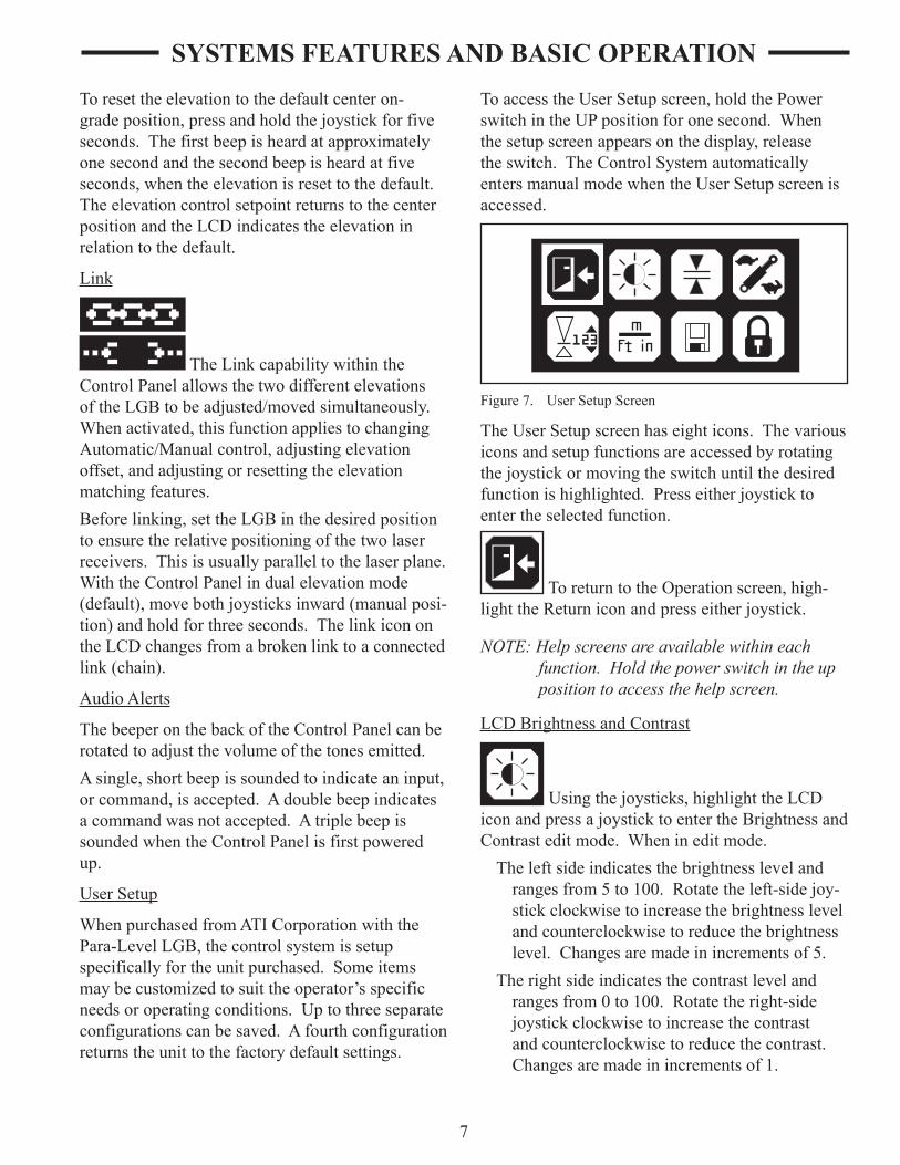
To access the User Setup screen, hold the Power switch in the UP position for one second. When the setup screen appears on the display, release the switch. The Control System automatically enters manual mode when the User Setup screen is accessed.
Figure 7. User Setup Screen
The User Setup screen has eight icons. The various icons and setup functions are accessed by rotating the joystick or moving the switch until the desired function is highlighted. Press either joystick to enter the selected function.
To return to the Operation screen, high-light the Return icon and press either joystick.
NOTE: Help screens are available within each function. Hold the power switch in the up position to access the help screen.
LCD Brightness and Contrast
Using the joysticks, highlight the LCD icon and press a joystick to enter the Brightness and Contrast edit mode. When in edit mode.
The left side indicates the brightness level and ranges from 5 to 100. Rotate the left-side joy-stick clockwise to increase the brightness level and counterclockwise to reduce the brightness level. Changes are made in increments of 5.
The right side indicates the contrast level and ranges from 0 to 100. Rotate the right-side joystick clockwise to increase the contrast and counterclockwise to reduce the contrast. Changes are made in increments of 1.

8
Figure 8. LCD Brightness and Contrast Edit Mode
Deadband (Accuracy)
Deadband refers to how tight a tolerance, or accuracy, is desired. Although a greater accu-racy is normally desired, if the system becomes unstable, overreacting between above grade and below grade, the deadband should be increased to minimize overreaction.Using the joysticks, highlight the deadband icon. Press a joystick to enter the Deadband edit mode.When in edit mode, the left side of the LCD dis-plays the elevation deadband in ft. The maximum elevation deadband is 0.170 ft. (2.00 in.). Rotating the left-side joystick changes the deadband for the elevation.
Setting the deadband too narrow may cause the LGB to become unstable. If this happens, increase the deadband or decrease the gain setting.
NOTE: Adjustment is for display deadband. De-fault control deadband is the same but may be set smaller during installation.
Figure 9. Deadband Edit Mode
Valve Speed
Valve speed relates to gain, or the speed at which the control system adjusts the Para-Level LGB. When operating in sandy or loose materi-als, decrease the valve speed for slower hydraulic speed. When operating in clay, dirt or tighter materials, increase the valve speed for a faster hydraulic speed. If the system becomes unstable, overreacting between above grade and below grade, decrease the valve speed.Using the joysticks, highlight the valve speed icon. Press the joystick to enter the valve speed edit mode. When in edit mode a single number appears, indicating the valve speed as a percentage between 0 and 100%.Rotate either joystick to adjust the valve speed. The factory default is 50%.
Figure 10. Valve Speed Edit Mode
Reference Elevation
This sets a reference elevation, displayed on the edge of the operation mode display. Only the elevation (left side) can be adjusted.Using the joysticks, highlight the reference eleva-tion icon. Press the joystick to enter the reference elevation edit mode. When in edit mode a single number appears on the left side of the display indi-cating the overall range of the display in operating mode. The units shown reflect the units selected.Rotate the left-side joystick to adjust the range.
SYSTEMS FEATURES AND BASIC OPERATION

9
Figure 11. Reference Elevation Edit Mode
Units of Measure
The units used to display information to the operator can be changed.Using the joysticks, highlight the units of measure icon. Press the joystick to enter the edit mode. When in edit mode, the currently selected units appear.To adjust the elevation units, displayed on the left side of the screen, rotate the left-side joystick.To adjust the slope units, displayed on the right side of the screen, rotate the right-side joystick.
Figure 12. Units of Measure Edit Mode
The available units are shown in Table 1.
Table 1. UnitsELEVATION SLOPE
Display Units Display UnitsFt feet % Percentage of slope
in inches ° Degrees of slope
Store and Recall Setup
This allows the operator to store three different setup configurations for future recall.
Using the joysticks, highlight the store and recall configuration icon. Press the joystick to enter the edit mode. When in edit mode, the left-side display and joystick manages the store function and the right-side display and joystick manages the recall function. Checksum values are also displayed to check copied setups.To store the current configuration, rotate the left-side joystick to the desired number on the display. When selected, press the joystick to store the setup configuration. A message appears asking “Do you want to store?” Select YES to store and NO to return to the previous menu.When YES is selected, a new name can be entered. Rotate the left-side joystick to scroll through the character choices. Move the joystick to the right to move to the next character. Up to seven characters may be entered. Once entered, the named setting appears on the store and recall screen for future selection.
DefaultA
Checksums:A2D3 186A
Figure 13. Store and Recall Edit Mode
To recall a saved configuration, rotate the right-side joystick to scroll through the selections. Highlight the desired configuration and press the right-side joystick to select it. A message appears asking “Do you want to recall the setup?” Select YES to recall and make the stored configuration the current configuration. Select NO to return to the previous menu.
Lock Setup
The current settings can be locked so changes to certain settings cannot be made without unlocking.
SYSTEMS FEATURES AND BASIC OPERATION

10
Using the joysticks, highlight the lock icon. Press the joystick to lock the configuration. The icon changes to indicate it is locked.When locked, the following settings cannot be changed:
deadbandvalve speedelevation and slope matching referenceelevation valuesunits of measurestore and recall settingslink sides
If changes to these settings are attempted, a "Locked" message appears on the screen.
ROTATING LASERThe Automatic Control System can operate with many models of rotating lasers. The laser must have a 360° rotating head with invisible or red beam and a speed of 8-40 RPS (revolutions per second). The faster the laser’s speed the more optimally the system will perform.
A
Figure 14. Rotating Laser
The rotating laser is mounted on a tripod located on the job site near where the LGB is operating. The rotating laser is the unit that creates the plane of laser light detected by the laser receiver.The rotating laser transmits a focused plane of laser light approximately 1000 feet (300 meters), optimal range for most rotating lasers, as it rotates.
Rotating lasers are available in single grade, dual grade, and steep slope versions. They can be quickly and easily aligned to job site requirements without complicated calculation of angles.A dual slope rotating laser can be configured for level, single slope, or dual slope applications. Simply enter the required percent of grade and align the rotating laser to the axis (direction) to be graded.
• Percent of Grade. The change in elevation for every 100 feet (30 meters) graded.
• Slope. The change in elevation per foot (meter).
Never look directly into a laser light or serious injury to the eye may occur. In general, inciden-tal exposure of the laser to the eye will not do damage. However, avoid looking into the beam whenever possible. Use a target for viewing the laser spot.
Use of any laser on a worksite is controlled by OSHA regulations found at 29 CFR 1926.54. Be familiar with these regulations before using any laser beacon used in conjunction with this system. Review and understand all literature provided with the laser system before operating.
Laser protection devices must be provided to all workers in the area if the laser system exceeds five (5) milliwatts. Refer to the literature pro-vided with the system to determine the power output. If unsure of the strength of the laser system, anti-laser eye protection should be provided to all workers.
SYSTEMS FEATURES AND BASIC OPERATION

11
LASER RECEIVERThe Apache Bullseye B5M laser receiver is a rug-ged, 360° electronic receiver that detects laser light generated by rotating lasers. The unit is designed to work with all common rotating laser beacons and detects both visible and invisible beams.The receiver does not have any on-board switches, All settings are made on the Control Panel. Power to the Bullseye B5M receiver also comes from the Control Panel. A small, built-in LED display provides grade elevation position, plus high and low lost beam indication.
Figure 15. Bullseye B5M
Two laser receivers are mounted on mast poles above the cutting edge of the box. An elevation receiver is mounted in the center and the tilt or slope receiver is mounted on the right side of the LGB. The receivers detect the plane of laser light produced by the rotating laser. The laser receivers provide grade information to the Control Panel based on the location of the plane of laser light. The Control Panel then has the valve assembly drive the LGB’s hydraulics accordingly.
CABLESThe cables are provided to connect the various components together into a system. Each connec-tor uses a unique number of pins to prevent the components from being connected incorrectly. At the Control Panel, each cable uses a press-and-twist style connector. After the cable is pressed into the socket, twist the ring clockwise until tight to secure it.
Never force a connector into a socket.
All cables must be secured with adequate cable length to avoid pinching, stretching and tight bending. Do not clamp cables to pipes or hoses that may generate high heat.
Cable Configurations
Power Cable – Supplies power to the system.
NOTE: The Control Panel supports both 12- and 24-volt machine systems. However, the valve is 12 volt only. Contact ATI Cor-poration for additional information when using a 24-volt system.
Junction Block/Receiver Cable – Provides a connection method for two receiver cables and the one connector on the Control Panel. The junction block end of the cable attaches to the Control Panel mounting bracket.Information from each laser receiver is coded to identify the receiver and, when the information is received, the Control Panel decodes the signals. This allows the signals to be passed to the Control Panel through a single connector.Receiver Cables (2) – Power the receiver and communicate grade information between each laser receiver and the Control Panel. The 90° connector attaches to the junction block end of the receiver cable and the straight end to the laser receiver(s). These are coiled cables that can hang freely between the Control Panel and laser receiver mounted on the mast.
SYSTEMS FEATURES AND BASIC OPERATION

12
A
B C
D
CONNECTOR 90° (4 Pin to Control Panel) CABLE 20 feet (6 meters)
Machine Ground A Black — Machine Ground B White — Machine Power C Red + Machine Power D Green +
Function Control Panel Wire Polarity 4 Pin Color
Figure 16. Power Cable
F
EG
DC
B
A
GA
BC D
EF
GA
BC D
EF
R
L
CONNECTOR 90° (7 Pin to Control Panel) CONNECTOR (2-7 Socket to Receiver) CABLE 3 feet (1 meters)
A — Red - Left Power B — Green - Data - C — White - Data + D — Black - Ground E — N/C F — N/C G — Orange - Right Power
A — Red B — Green C — White D — Black E — N/C F — N/C G — N/C
A — Orange B — Green C — White D — Black E — N/C F — N/C G — N/C
N/C - Not Connected
Figure 17. Receiver Junction Cable
FEG
DCB
A
GA
BC D
EF
CONNECTOR 90° (7 Pin to Control Panel) CONNECTOR (7 Socket to Receiver) CABLE 12 feet (4 meters)
N/A - Not AssignedN/C - Not Connected
+8.5V Out A A Red Communication B B Green Communication C C White Ground (Signal) D D Black High Power Return N/C E N/C High Power Supply N/C F N/C -------------------- N/A G N/C
Function Control Panel Receiver Wire 7 Pin 7 Socket Color
Figure 18. Receiver Cable
SYSTEMS FEATURES AND BASIC OPERATION

13
HGF
E DCB
A
JI
12
CONNECTOR 90°(10 Pin to Control Panel) CONNECTOR (3 Socket to Valve) CABLE 3 feet (1 meter)
J2
C1
J1
LH Raise/Lower E 1 LH Ground I 3 LH Switch Power C 4 RH Raise/Lower H 1 RH Ground J 3 RH Switch Power D 4
Function Control Panel Elevation/Left Slope/Right 10 Pin
Figure 19. Solenoid Cable
32
13
21
CDFGBA
FEG
DCB
A
AU
TOA
UTO
MA
N
RA
ISE
LOW
ER
CONNECTOR 90° (7 Socket to Control Panel) REMOTE SWITCH CABLE 10 feet (3 meters)
Auto/Manual Left A White Raise/Lower Left B Brown Auto/Manual Right C Red Raise/Lower Right D Grey Battery Positive F Black Battery Negative G Blue
Function Control Panel Wire 7 Pin Color
Figure 20. Remote Switch Cable
SYSTEMS FEATURES AND BASIC OPERATION
14
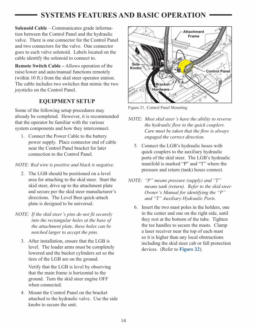
Solenoid Cable – Communicates grade informa-tion between the Control Panel and the hydraulic valve. There is one connector for the Control Panel and two connectors for the valve. One connector goes to each valve solenoid. Labels located on the cable identify the solenoid to connect to.Remote Switch Cable – Allows operation of the raise/lower and auto/manual functions remotely (within 10 ft.) from the skid steer operator station. The cable includes two switches that mimic the two joysticks on the Control Panel.
EQUIPMENT SETUPSome of the following setup procedures may already be completed. However, it is recommended that the operator be familiar with the various system components and how they interconnect.
1. Connect the Power Cable to the battery power supply. Place connector end of cable near the Control Panel bracket for later connection to the Control Panel.
NOTE: Red wire is positive and black is negative.
2. The LGB should be positioned on a level area for attaching to the skid steer. Start the skid steer, drive up to the attachment plate and secure per the skid steer manufacturer’s directions. The Level Best quick-attach plate is designed to be universal.
NOTE: If the skid steer’s pins do not fit securely into the rectangular holes at the base of the attachment plate, these holes can be notched larger to accept the pins.
3. After installation, ensure that the LGB is level. The loader arms must be completely lowered and the bucket cylinders set so the tires of the LGB are on the ground.
Verify that the LGB is level by observing that the main frame is horizontal to the ground. Turn the skid steer engine OFF when connected.
4. Mount the Control Panel on the bracket attached to the hydraulic valve. Use the side knobs to secure the unit.
SYSTEMS FEATURES AND BASIC OPERATION
2
1
AttachmentFrame
HardwareBracket
SideKnobs
Control Panel
Figure 21. Control Panel Mounting
NOTE: Most skid steer’s have the ability to reverse the hydraulic flow to the quick couplers. Care must be taken that the flow is always engaged the correct direction.
5. Connect the LGB’s hydraulic hoses with quick couplers to the auxiliary hydraulic ports of the skid steer. The LGB’s hydraulic manifold is marked “P” and “T” where the pressure and return (tank) hoses connect.
NOTE: “P” means pressure (supply) and “T” means tank (return). Refer to the skid steer Owner’s Manual for identifying the “P” and “T” Auxiliary Hydraulic Ports.
6. Insert the two mast poles in the holders, one in the center and one on the right side, until they rest at the bottom of the tube. Tighten the tee handles to secure the masts. Clamp a laser receiver near the top of each mast so it is higher than any local obstructions including the skid steer cab or fall protection devices. (Refer to Figure 22).

15
2
1
2
1
ControlPanel
HydraulicValve
JunctionBlock
Bracket
Figure 23. Junction Block and Laser Receiver Cables
9. Connect the straight end of one receiver cable to the base of the center mast-mounted laser receiver and the 90° end to the Junction Block connector of the Junction Block/Receiver cable labeled L (left).
SYSTEMS FEATURES AND BASIC OPERATION
2
1
TeeHandles
Plane of Laser Light
Main Frame
Slope Frame
LaserBeacon
Laser Receivers
Mast Poles
MastHolders
Figure 22. Components of the Automatic Control System on a Skid Steer
Cables must be securely fastened and pinch/rubpoints eliminated. Do not fasten to hydraulic lines which may operate at high temperatures. Ensure sufficient cable length to allow move-ment of the machine.
7. Connect the 7-pin remote switch connector to the 7-socket connector on the Control Panel. Make sure the switch is accessible to the operator.
8. Connect the 90° end of the Junction Block/Receiver cable to the Control Panel. Attach the other end to the side of the Control Panel mounting bracket.

16
10. Repeat step 9 for the other cable and laser receiver mounted on the right-side mast, connecting it to the Junction Block labeled R (right).
11. Connect the 90° end of the Solenoid cable to the back of the Control Panel. Connect the straight end (molded) of the Solenoid cable labeled SLOPE to the forward valve solenoid and the other straight end connector (not labeled) to the rearward valve solenoid.
12. Connect the 90° end of the Power Cable to the back of the Control Panel. The terminal end was previously wired to the battery.
HYDRAULICS
Danfoss PVG-32 Hydraulic Valve
The hydraulic valve is setup at the factory and should not need any adjustments. If there are any changes required, they should be done by an autho-rized factory technician.
Check ValveDO NOT REMOVE
HydraulicValve Handles
Figure 24. Hydraulic Valve (Danfoss PVG-32)
NOTE: Do not remove the check valve. Removal will void the warranty.
The handles are for manual actuation of the valve.
Hydraulic Hose Connection
Pressure Hose
Return/Tank HoseCONNECT FIRST
Figure 25. Hydraulic Hose Connections to Skid Steer
The return line must be connected before the pressure line. Pressurizing the valve without an outlet will damage the valve and void the valve warranty.
NOTE: Check the manufacture of your skid steer for the correct hose connections.
JOB SITE SET-UPThe following are guidelines for setting up the rotating laser for both level job sites and sloped job sites:
• Choose a location for the rotating laser where obstructions, such as trees and buildings, will not block the plane of laser light. The laser receiver needs to be able to sense the plane of laser light at all times.
• Whenever possible, set up the rotating laser and laser receiver at a height above the machine’s cab. This prevents the cab or rollover structure from blocking the plane of laser light as the machine moves around the job sites.
• The recommended head speed for the Automatic Control System is 20 RPS (revolu-tions per second). At 20 RPS, the rotating laser updates the laser receiver 20 times per second.
SYSTEMS FEATURES AND BASIC OPERATION

17
Set-Up for Level Grading
If the job site is to be level, the set-up of the rotat-ing laser is simple. Since no slope is required in either axis, the rotating laser does not need to be aligned. The rotating laser will provide a level plane of laser light in all directions.
1. Locate the rotating laser following the guidelines above.
2. Power tn rotating laser. Level the rotating laser (some rotating lasers will automatically level, others will require manual adjust-ment).
3. Set the counters for both axis at 0.000% (if needed, see the Rotating Laser Operation Manual).
4. Bench the machine. See the “Benching and Operating” procedure in this section.
Set-Up for Sloped Grading
If the job site is to be graded for a single or dual slope, the rotating laser requires its axis to be aligned for the job site. The rotating laser will then provide a plane of laser light at the required slope(s).The following procedures are two typical examples of job sites requiring sloped grades. Remember, each job site is unique, so consider the following methods as guidelines and not as the only methods possible.
Method One:
1. Set a minimum of two grade stakes exactly in line with one of the axis to be graded.
2. Place the rotating laser in line with the two grade stakes.
Figure 26. Method One: Align Rotating Laser with Grade Stakes
3. Switch on the rotating laser. Level the rotating laser (some rotating lasers will automatically level, others will need manual adjustment).
4. Set the counter on the rotating laser for both axis to 0.0000% (If needed, see the Rotating Laser Operation Manual).
Figure 27. Sight Over Rotating Laser
5. Roughly align one of the axis to the grade stakes by sighting over the top of the rotating laser (Refer to Figure 27).
6. Align the plane of laser light.a. Set a grade rod with Rod Eye Receiver
on the far grade stake and adjust the rod until the Rod Eye Receiver indicates “On Grade.”
b. On the axis not aligned with the stakes, enter 5.000% on the rotating laser. Allow the rotating laser to level itself to this new position, if needed.
c. Check the Rod Eye Receiver again.
SYSTEMS FEATURES AND BASIC OPERATION

18
• If the Rod Eye Receiver indicates “On Grade”, the plane of laser light is aligned correctly.
• If the Rod Eye Receiver indicates the plane of laser light is too high or too low, have a second person rotate the rotating laser on the tripod in small steps until the Rod Eye Receiver indicates “On Grade.”
7. Enter on the rotating laser the required percent of grade for each axis and allow the rotating laser to level itself again.
8. Bench the machine. See the “Benching and Operating Your Machine” procedure in this section.
Method Two:
NOTE: This procedure requires that the elevations of the grade stakes are correct and aligned to the slope or percent of grade required.
1. Set a minimum of two surveyed grade stakes. The stakes must have elevation information.
Figure 28. Grade Stake with Elevation Mark
2. Place the rotating laser a few feet (meters) behind the first grade stake and in line with one of the far grade stakes (it is not critical to align the rotating laser exactly). (Refer to Figure 29.)
NOTE: Follow the guidelines at the beginning of this section when placing the rotating laser.
3. Switch on the rotating laser. Level the rotat-ing laser.
4. Roughly align one of the axis to the grade stakes by sighting over the top of the rotating laser (Refer to Figure 29).
5. Set both counters on the rotating laser to the required percent of grade (If needed, see the Rotating Laser Operation Manual).
Laser Beacon
Grade Stake
Grade Stake
Figure 29. Method Two: Align Rotating Laser with Grade Stakes
NOTE: The Grade Rod must be held plumb for each of the readings taken in the following steps.
6. Establish the H. I. (height of the instrument) for the plane of laser light.a. Align the bottom of the Grade Rod to the
mark on the near grade stake.b. Adjust the Rod Eye Receiver up and down
until it indicates “On Grade.”c. Adjust the Rod Eye Receiver for any cut
or fill amount indicated by the grade stake.• If the grade stake shows a cut, extend
the Grade Rod and Rod Eye by the amount shown as a cut.
• If the grade stake shows a fill, lower the Rod Eye by the amount shown as fill.
SYSTEMS FEATURES AND BASIC OPERATION

19
7. Align the plane of laser light.a. Align the bottom of a Grade Rod to the
mark on the far grade stake.b. Check the Rod Eye Receiver.
• If the Rod Eye Receiver indicates “On Grade,” the plane of laser light is aligned at the correct slope.
• If the Rod Eye Receiver indicates the plane of laser light is too high or too low, have a second person rotate the Rotating Laser on the tripod in small steps until the Rod Eye Receiver indi-cates “On Grade.”
NOTE: If it was necessary to rotate the rotating laser a significant amount at the far stake, then the original reading at the near stake may be out of tolerance. Check the set-ting again and make minor adjustments as required.
8. Bench the machine.
NOTE: If needed, check the elevations on both the plane of laser light and the grade stake elevations by setting the bottom of the Grade Rod at any stake’s grade mark and checking the Rod Eye Receiver for the “On Grade” indication.
BENCHING AND OPERATINGBefore benching, the plane of laser light must be set at its proper slope. Benching is the process of set-ting the relationship between the laser receiver and the rotating laser or benchmark. Failure to properly bench the system before grading will result in an unacceptable grade.The goal is to have the LGB approximately 1/2 full during operation. If, during rough grading, a lot of material needs to be removed from a site, the elevation offset feature can be used to rough-in the grade. As material is removed, the elevation offset can be reduced and the site regraded. This may need to be repeated several times until finished grade is achieved.
Benching
NOTE: Finish grade can be checked several times during the grade process to “zero” in on final grade.
1. Turn the system on using the Power switch.2. Ensure the system is in manual control and
dual elevation mode (default).3. Turn the rotating laser ON and set to 0.0%
slope.
Benchmark
Figure 30. Benching the Para-Level LGB with a Level Plane
4. Move the machine to an area to be graded. Using the system controls, lower the cutting edge to finished grade. This is normally done close to the rotating laser.
NOTE: If necessary, a small area may need to be manually graded to obtain sufficient space for benching.
5. Use a bubble level to level the LGB. Re-check the cutting edge to ensure it remains at the finished grade.
6. Raise the Power switch and hold in the I position for 1 second to access the User Setup menu.
7. From the User Setup screen on the Control Panel, highlight the Deadband (Accuracy) icon and press the joystick.
8. Select an appropriate deadband for the job and conditions.
9. Press the joystick twice to exit the deadband setup.
SYSTEMS FEATURES AND BASIC OPERATION
20
10. Adjust the height of each laser receiver until the appropriate center Grade Position LED cluster is lit, indicating it is “on grade.” Tighten the mounting knobs on each laser receiver securely after adjustment.
For grading to level, skip to step 14. For grading on a slope, continue from step 11.
11. For sloped grades, the rotating beacon can now be adjusted to the proper slope.
12. With the LGB remaining at finished grade, raise or lower the rotating beacon on the tripod until the laser receiver on the center mast indicates the elevation is “on grade.”
Always have system in Manual control when not operating the skid steer.
13. Using all applicable safety precautions, set the Control Panel to automatic control. Drive the skid steer a short distance to allow the control system to adjust the LGB to the grade.
14. Both elevations should now indicate 0.0. Slope offset and other adjustments for rough grading can be made and grading can begin.
15. After grading a small area, check the grade using a grade rod. If required, adjust the LGB using this procedure.
NOTE: Most materials graded must later be com-pacted. To compensate for the compacting distance, raise the rotating beacon. This raises the cutting edge by the same dis-tance. The distance the rotating beacon is raised depends on the material.
Benching with a Rod Eye
To bench the laser receiver follow the process listed below:
1. Turn on the rotating beacon. Attach a Rod Eye to a measuring pole and turn on. Set the base of the measuring pole on the benchmark and adjust the measuring pole so the Rod
Eye emits a solid “On Grade” tone (com-pensate for slab thickness and compaction if needed).
2. Find an area to be graded that is close to specified grade. Making sure the control system is in manual mode, start the skid steer, engage the auxiliary hydraulics and move the unit to that location. Manually raise or lower the LGB’s cutting edge until it is even with the bottom of the measuring pole when the Rod Eye is emitting the “On Grade” tone or resting on the ground if already at grade.
NOTE: The elevation measurement must be made as close to the laser receiver as possible, i.e., in the middle or on the right-side.
3. With the control system deadband set as required for the job, move the laser receiver to a height on the mast pole where it indi-cates the beam in the “On Grade” position and is unobstructed by any object.
NOTE: Operator may prefer to turn the face of the laser receiver towards the operator for easy viewing.
4. Move the Rod Eye to the right side of the blade. Using the tilt function (right-side joystick), manually raise or lower the LGB’s cutting edge until it is even with the bottom of the measuring pole while the Rod Eye is emitting the “On Grade” tone or resting on the ground if already on grade. Repeat step 3.
Operation
After the LGB is connected and the Automatic Control System is calibrated, operation can begin.The operational goal is to drive over the area to be graded with the box 1/2 full of material and the green LEDs on the grade indicators always illumi-nated.
1. When seated in the operator’s seat, start the skid steer. Turn the control system on and set the system to automatic control. For initial or rough-cut situations, use a higher deadband setting.
SYSTEMS FEATURES AND BASIC OPERATION

21
NOTE: Most graded materials must later be com-pacted. To compensate for the compacting distance, raise the rotating beacon. This raises the cutting edge by the same dis-tance. The distance the rotating beacon is raised depends on the material.
2. Drive the machine forward or reverse (the Para-Level LGB has front and rear cutting edges). The Automatic Control System constantly senses the plane of laser light to maintain the cutting edge of the box at the required elevation. Note the following during operation:
• In some situations, the Automatic Control System may require a cut deeper than the machine can handle. The machine may lose traction, stall the engine, or the wheel frame will be lifted off the ground to the maximum stroke of the cylinder as the cutting edge tries to reach finished grade. If this occurs, set the system to manual control and use the joysticks to raise the cutting edge until the machine can move the material. Make multiple passes to cut the area closer to finished grade and then go back to automatic control. This allows the high spots to be gradually removed.
• If one of the Control Panel or laser receiver grade lights are blinking, it indicates the direction of the last eleva-tion prior to passing out of the laser beam. If necessary, do the rough grad-ing and then bench the LGB again.
NOTE: In rough grading situations, use the Au-tomatic Control System as an “Indicate Only” system and operate the machine under manual control. After the area has been rough graded, switch to automatic control.
Always have system in Manual control when not operating the skid steer.
3. After several passes with the LGB, stop and turn off the skid steer. Place the base of the measuring pole on the graded area and check grade elevation.
4. After a rough grade is achieved, the Deadband (Accuracy) may be changed to a narrower setting as required to meet the job tolerance requirements. With a tighter deadband, the speed of the skid steer needs to be decreased for optimum finish.
SYSTEMS FEATURES AND BASIC OPERATION

22
SYMPTOM POTENTIAL CAUSE REMEDYControl Panel lamps do not light. Control Panel not turned on.
Power cable not connected to Control Panel.
Power cable not providing power to the Control Panel.
Fuse blown.
Electrical short.
Push the Power ON/OFF Switch.
Connect power cable to Control Panel.
Check that the Power Cable is connected to the battery. The red wire connects to the positive (+) post and the black wire connects to the negative (–) post.
Remove the Power Cable from the Control Panel and, using a volt meter, check for a minimum of 11 volts DC.
Check the fuse.
Disconnect all cables except the Power Cable. If the lamps still do not cycle when the Control Panel is turned on, contact the local Apache Technolo-gies dealer.
Laser receiver does not display grade. No Rotating Laser in range.
Laser beam blocked.
Electrical short.
Ensure laser receiver is within operating range of Rotating Laser.
Ensure beam is striking middle of the laser receiver
Check and clean glass covering the laser receiver’s photo cells.
Check for obstructions keeping laser receiver from seeing the Rotating Laser.
If LEDs do not cycle when Control Panel is turned On, contact the local Apache Technologies dealer.
Laser receiver does not display grade (cont)
Laser receiver not receiving power.
Check Fuse in the Control Panel.
Check Receiver Cable for damage. Use an Ohm meter to check continuity.
Disconnect and reconnect the laser receiver Cable making sure the connectors on the ends are seated into the laser receiver and Junction Block/Receiver Cable correctly.
Check that the Control Panel is com-municating with the laser receiver, indicated by the Control Source Indicator icon on the LCD.
TROUBLESHOOTING

23
SYMPTOM POTENTIAL CAUSE REMEDYBox has trouble staying on grade. Rotating Laser out of range.
Laser beam being reflected.
Multiple laser beams.
Laser deadband set too narrow.
Travel speed is too fast for grade toler-ance.
Hydraulic response too quick.
Ensure laser receiver is within specified operating range of Rotating Laser.
Ensure Rotating Laser’s light is not reflecting off other surfaces (win-dows, windshields, mirrors, etc.) causing multiple readings by the laser receiver.
Ensure that there are no other lasers operating on the job site or nearby.
Ensure the Deadband (Accuracy) setting is appropriate for rough grading.
Slow down.
Decrease the Valve Speed setting.
Laser Grading Box does not raise or lower.
Control Panel not turned on.
No hydraulic flow to Laser Grading Box.
Cables not connected correctly.
Push the Power switch.
Ensure hydraulic control handle of skid steer is in correct position.
Ensure auxiliary hydraulics are ON or in continuous flow mode.
Check Valve cable, valve and valve solenoids for visible damage.
Move directional valve spool manually using the handles found in the manual canister. (Refer to Figure 24.)
Be sure to stay clear of any moving parts of the Laser Grading Box.
If the Laser Grading Box moves, refer to Electrical problems. If the Laser Grading Box does not move, refer to Hydraulic problems.
Electrical Problems
Hydraulic Problems
Check Valve cable, valve and valve solenoids for visible damage.
Use an Ohm meter to check cable for continuity.
Contact ATI Corporation for help troubleshooting the hydraulic manifold.
TROUBLESHOOTING

24
SYMPTOM POTENTIAL CAUSE REMEDYLaser Grading Box moves in unex-
pected/erratic direction.Solenoid cable installed incorrectly. Verify termination marked “Elevation” is
installed in socket of Elevation bank on Danfoss valve. Confirm respec-tive termination on Slope bank.
TROUBLESHOOTING

25
SPECIFICATIONS AND MAINTENANCE
MAINTENANCEThe rugged and durable Automatic Control System is built to last, but as with all equipment, a few minutes of routine care, maintenance, and cleaning can extend the life of the system.
Storage and Transport
Most often the LGB and its hydraulic controls remain on the machine. However, the Control Panel, Laser Receiver, Coiled Receiver Cable and Solenoid Cable should be stored in a safe, protected place when not in use. Protect the cable connec-tions by installing the covers supplied.
Cleaning
The laser receiver is completely sealed and purged with dry nitrogen. It requires no maintenance other than periodic checking to be sure its mounting structure is tight and secure.The Control Panel is water-resistant. It can be cleaned with mild soap, water, and a damp, soft cloth. Do not submerge the Control Panel or direct high pressure spray at it. Do not use a dry cloth to wipe the laser receiver or Control Panel as scratch-ing may occur.
Cables and Hoses
Check all cables and hoses regularly for signs of wear and damage. Keep cable connections clean and free from dirt and corrosion. If a cable has been damaged, do not attempt to repair. Incorrect or poor connections can cause damage to your Automatic Control System.When applicable, check the hydraulic hoses. Look for areas where the hoses could rub against each other or another object as they expand and contract under pressure. Check the hydraulic fittings for tightness.
Machine
Check areas that affect the Automatic Control system function and accuracy, such as looseness or play in the cylinders or wear on the box’s cutting edge. Looseness in the connection to the skid steer, such as in the adaptor plate, will cause inaccurate depth positioning.
Also check the skid steer routinely for wear to its components, such as loader pins and 3-point link-age, ensuring it is operating properly.
Calibration
Perform periodic calibration checks of the Rotating Laser System as outlined in its Operation Manual to ensure accurate performance.
Loader Hydraulics
Change the oil and filter per loader manufacturer recommendations to ensure proper function of your Level Best grading box.
SERVICEIf the Automatic Control System is not functioning properly, the first step is to determine the problem component. Use the Troubleshooting Chart to determine possible causes and remedies. The following test equipment is needed:
• Voltage/Ohm Meter• Rotating Laser or Laser Simulator
Use the Cable Wiring Diagrams on Pages 12 and 13 to troubleshoot electrical problems.The Control Panel provides diagnostic codes to aid in troubleshooting and diagnostics. If a 5-digit code appears, contact ATI Corporation for assis-tance in diagnosing the code.If the code 1505 appears, it indicates communica-tion with the laser receiver(s) has been lost. Check the cable connections.
To prevent serious damage to the Automatic Control System, never replace a fuse with a fuse that has a higher amperage value.
The Automatic Control System is a highly sophisticated electronic system. Do not attempt repairs to the components. Contact Apache Technologies, Inc. or your local dealer if you have any problems.

26
SPECIFICATIONS AND MAINTENANCE
SPECIFICATIONS
Dimensions
Model PD-72 PD-84 PD-96
Box Width 72 in. (183 cm)
84 in. (213 cm)
96 in. (244 cm)
Overall Width 75.25 in. (191 cm)
87.25 in. (222 cm)
99.25 in. (252 cm)
Total Length 71.25 in. (181 cm)
Box Capacity, Front 11.5 ft3 (0.33 m3)
13.4 ft3 (0.38 m3)
15.3 ft3 (0.43 m3)
Box Capacity, Rear 7.0 ft3 (0.20 m3)
8.0 ft3 (0.23 m3)
9.0 ft3 (0.25 m3)
Weight 1,885 lbs. (855 kg)
1,935 lbs. (878 kg)
1,985 lbs. (900 kg)
Control Panel CB52Main Display ................................LCDOn-Grade LED’s ..........................GreenHigh/Low LED’s .........................RedOperating Voltage .......................10 to 30 Volts DC, reverse polarity protectedElectrical Connection ..................Standard military typeValve Compatibility ....................Proportional Time (On/Off), Proportional Current, and Proportional Volt-
ageMaximum Current .......................5 Amps per driverRemote Switch ............................Two; Raise/Lower, Auto/Manual multi-directionDeadband Range ..........................0 to 2.0 in. (0 to 50 mm)Weight .........................................5 lbs. (2.25 kg)Dimensions .................................7.0 x 5.5 x 5.5 in. (178 x 140 x 140 mm)Operating Temperature ...............-4 to 140° F (-20 to 60° C)Laser Receiver Bullseye B5MBeam Reception ..........................360°Operating Range .........................2000 ft. (610 m) radius, laser dependentLaser RPM ..................................Minimum - 105 ; Maximum - 1200Vertical Reception .......................6.75 in. (170 mm)Accuracy .....................................Set at Control BoxPower ..........................................Supplied by Control PanelLED Display ...............................Mini display for set-up Red - Hi, Low, On GradeOut of Beam Indication ...............High and LowDimensions (L x W x D) ..............13.50 x 5.58 x 5.88 in. (343 x 142 x 149 mm)Mounting Pipe ..............................1.66 to 2.00 in. O.D. round tube (42 to 50 mm) and 1-1/2 in. (38 mm)
square tubeOperating Temperature ...............-4 to 140° F (-20 to 60° C)

27
2
1
ITEM NAME FREQUENCY LUBE TYPE
1. Wheel Hub (2)** Annually EP*
* EP - Multi-Purpose Grease. ** Bearings must be pulled apart cleaned and packed once a year. Inspect grease seals and replace if necessary.
NOTES: 1. Check Hydraulic System Components for wear and/or leaks. 2. Check and tighten all bolts and nuts for scraper blade and end blades, weekly.
Seal
SealHub
Bearing
Bearing
End Blades
1
Scraper Blade
Figure 31. Lube and Maintenance Chart
28
INDEX
AAudio Alerts ....................................................................... 7Automatic/Manual Control ................................................ 6
BBenching .......................................................................... 19Benching And Operating ................................................. 19Benching the Para-Level LGB with a Level Plane ......... 19Benching with a Rod Eye ................................................ 20Bullseye B5M .................................................................. 11
CCable Configurations ....................................................... 11Cables .............................................................................. 11Cables and Hoses - Maintenance ..................................... 25Calibration ....................................................................... 25Cleaning ........................................................................... 25Components ....................................................................... 1Control Panel ..................................................................... 2Control Panel CB52 - Specifications ............................... 26Control Panel Display ........................................................ 4
DDanfoss PVG-32 Hydraulic Valve ................................... 16Deadband (Accuracy) ........................................................ 8Dimensions ...................................................................... 26Disclaimer .......................................................................... i
EElevation/Slope Matching ................................................. 6Elevation/Slope Offset (Reference Adjustment) ............... 6Equipment Setup ............................................................. 14
FFront Control Panel Switches ............................................ 3
GGrade Indicators ................................................................ 5Grade Stake with Elevation Mark ................................... 18
HHydraulics ........................................................................ 16
IIndex ................................................................................ 28
JJob Site Set-Up ................................................................ 16Junction Block/Receiver Cable ....................................... 11
LLaser Receiver ................................................................. 11Laser Receiver Bullseye B5M - Specifications ............... 26LCD Brightness and Contrast ............................................ 7Link .................................................................................... 7List of Illustrations ......................................................... viiList of Tables ................................................................. viiiLoader Hydraulics ........................................................... 25Lock Setup ......................................................................... 9Lube and Maintenance Chart ........................................... 27
MMachine ........................................................................... 25Maintenance .................................................................... 25Method One: Align Rotating Laser with Grade Stakes ... 17Method Two: Align Rotating Laser with Grade Stakes ... 18
OOperation ..................................................................... 5, 20
PPower Cable ..................................................................... 11Purpose .............................................................................. 1
RRaise/Lower ....................................................................... 6Rear Control Panel Connections ....................................... 4Rear View of the Control Panel ......................................... 4Receiver Cables ............................................................... 11Reference Elevation ........................................................... 8Remote Switch Cable ...................................................... 14Rotating Laser ................................................................. 10
SSafety Information ............................................................. vSafety Precaution Definitions ............................................ vService ............................................................................. 25Set-Up for Level Grading ................................................ 17Set-Up for Sloped Grading .............................................. 17Sight Over Rotating Laser ............................................... 17Solenoid Cable ................................................................. 14Specifications .................................................................. 26Specifications and Maintenance ...................................... 25Storage and Transport ...................................................... 25Store and Recall Setup ....................................................... 9Systems Features and Basic Operation .............................. 1
TTable of Contents ............................................................. iiiTilt 6Troubleshooting ............................................................... 22

29
INDEX
UUnits of Measure ............................................................... 9User Setup ......................................................................... 7
VValve Speed ....................................................................... 8
WWarranty .......................................................................... vi

ATI CorporationNew Holland, PA 17557
Phone (717) 354-8721 • FAX (717) 354-21621-800-342-0905
www.level-best.com